Product Overview
Revised: 08 August 2017
This chapter describes the Catalyst 4500 E-series switches and contains these sections:
Note The Catalyst 4500 series switches are described in a separate publication.
Tip For additional information about the Cisco Catalyst 4500 E-series switches (including configuration examples and troubleshooting information), see the documents listed on this page:
http://www.cisco.com/en/US/products/hw/switches/ps4324/index.html
Catalyst 4503-E Switch
The Catalyst 4503-E switch is a 3-slot horizontal chassis supporting redundant power supplies, a single supervisor engine, and slots for up to two modules. Figure 1-1 shows a front view of the Catalyst 4503-E switch with the chassis major features identified.
Figure 1-1 Catalyst 4503-E Switch Chassis (Front View)
|
|
Fan tray assembly |
|
Supervisor engine (slot 1) |
|
|
Switching modules (slots 2 and 3) |
|
Redundant power supplies |
Table 1-1 describes the features of the Catalyst 4503-E switch chassis.
Table 1-1 Catalyst 4503-E Switch Features
|
|
|
Chassis |
Three horizontal slots. Slots are numbered from 1 (top) to 3 (bottom). |
Supervisor engines |
- Supports the following supervisor engines:
– Supervisor Engine 9-E – Supervisor Engine 8L-E – Supervisor Engine 8-E – Supervisor Engine 7L-E – Supervisor Engine 7-E Note Refer to your software release notes for the minimum software release versions required to support the supervisor engines.
- Supervisor engines must be installed in slot 1.
- Supervisor engine redundancy is not supported in this chassis.
Note Check your software release notes for any restrictions on the type of module that can be installed. |
Modules |
- Supports up to two Catalyst 4500 series modules.
- Some Catalyst 4500 series modules may:
– Not be supported – Require that you install a specific supervisor engine model – Have chassis slot restrictions – Require a specific software release level to operate Note Check your software release notes for specific support information. |
Backplane |
48 Gbps full duplex per slot (96 Gbps) |
Fan tray |
- The chassis supports one hot-swappable fan tray. One fan tray model is available:
– WS-X4593-E
- The fan tray contains six individual fans. The individual fans are not field replaceable; you must replace the fan tray in the event of a fan failure.
- Air is drawn in on the right side of the chassis and exhausted on the left side of the chassis.
- Fan tray STATUS LED (located on the fan tray front panel)
– Red—One or more individual fans have failed. – Green—Fan tray is operating normally. |
Power supply |
- Supports one or two power supplies. The following power supplies are supported:
– 1000 W AC-input power supply (PWR-C45-1000AC) – 1400 W AC-input power supply (PWR-C45-1400AC) – 1300 W AC-input power supply (PWR-C45-1300ACV) – 2800 W AC-input power supply (PWR-C45-2800ACV) – 4200 W AC-input power supply (PWR-C45-4200ACV) – 6000 W AC-input power supply (PWR-C45-6000ACV) – 9000 W AC-input power supply (PWR-C45-9000ACV) – 1400 W DC-input power supply, triple-input (PWR-C45-1400DC) – 1400 W DC-input power supply with integrated PEM (PWR-C45-1400DC-P) – External AC power shelf (WS-P4502-1PSU)
- All Catalyst 4500 series AC-input power supplies require single-phase source AC.
- Source AC can be out of phase between multiple power supplies or multiple AC-power plugs on the same power supply because all AC power supply inputs are isolated.
- Single power supplies are installed in the left power supply bay. The second power supply is installed in the right power supply bay.
Note For proper operation of the power supply OUTPUT FAIL LED, systems with single power supplies must be configured with a minimum of one fan tray and one supervisor engine. Systems with dual power supplies must have a minimum configuration of one fan tray, one supervisor engine, and one additional module. Failure to meet these minimum configuration requirements can cause a false power supply output fail signal. |
Table 1-2 lists the environmental and physical specifications of the Catalyst 4503-E switch.
Table 1-2 Catalyst 4503-E Switch Specifications
|
|
|
Temperature, ambient |
- Operating: 32° to 104°F (0° to 40°C)
- Nonoperating and storage: –40 to 167°F (–40 to 75°C)
|
Humidity (RH), ambient (noncondensing) |
- Operating: 10% to 90%
- Nonoperating and storage: 5% to 95%
|
Altitude,
operating and nonoperating |
–196 to 6561 ft (–60 to 2000 m) |
Sound pressure level |
- One PS: 63.6 dBA at low speed and 62.3 dBA at full speed
- Two PS: 65 dBA at low speed and 65.4 dBA at full speed
|
Dimensions (H x W x D) and rack units (RU) |
- 12.25 x 17.31 x 12.50 in. (31.12 x 43.97 x 31.70 cm)
- 7 RU
|
Weight |
- 32.25 lbs (14.63 kg) minimum weight
- 75 lbs (34 kg) maximum weight
|
Airflow |
- Chassis fan tray: Right to left
- Power supply fan: Front to back
|
Catalyst 4506-E Switch
The Catalyst 4506-E switch is a 6-slot horizontal chassis supporting redundant power supplies, a single supervisor engine, and slots for up to five modules. Figure 1-2 shows a front view of the Catalyst 4506-E switch with the chassis major features identified.
Figure 1-2 Catalyst 4506-E Switch (Front View)
|
|
Fan tray assembly |
|
Supervisor engine (slot 1) |
|
|
Switching modules (slots 2 to 6) |
|
Power supplies |
Table 1-3 describes the features of the Catalyst 4506-E switch chassis.
Table 1-3 Catalyst 4506-E Switch Features
|
|
|
Chassis |
Six horizontal slots. Slots are numbered from 1 (top) to 6 (bottom). |
Supervisor engines |
- Supports the following supervisor engines:
– Supervisor Engine 9-E – Supervisor Engine 8L-E – Supervisor Engine 8-E – Supervisor Engine 7L-E – Supervisor Engine 7-E Note Refer to your software release notes for the minimum software release versions required to support the supervisor engines.
- Supervisor engines must be installed in slot 1.
- Supervisor engine redundancy is not supported in this chassis.
|
Modules |
- Supports up to five Catalyst 4500 series modules.
- Some Catalyst 4500 series modules may:
– Not be supported – Require that you install a specific supervisor engine – Have chassis slot restrictions – Require a specific software release level to operate
- Check your software release notes for specific support information.
|
Backplane |
48 Gbps full duplex per slot (240 Gbps) |
Fan tray |
- The chassis supports a single hot-swappable fan tray. One fan tray model is available:
– WS-X4596-E
- The fan tray contains four individual fans. The individual fans are not field replaceable; you must replace the fan tray in the event of a fan failure.
- Air is drawn in on the right side of the chassis and exhausted on the left side of the chassis.
- Fan tray STATUS LED (located on the fan tray front panel)
– Red—One or more individual fans have failed. – Green—Fan tray is operating normally. |
Power supply |
- Supports one or two power supplies. The following power supplies are supported:
– 1000 W AC-input power supply (PWR-C45-1000AC) – 1400 W AC-input power supply (PWR-C45-1400AC) – 1300 W AC-input power supply (PWR-C45-1300ACV) – 2800 W AC-input power supply (PWR-C45-2800ACV) – 4200 W AC-input power supply (PWR-C45-4200ACV) – 6000 W AC-input power supply (PWR-C45-6000ACV) – 9000 W AC-input power supply (PWR-C45-9000ACV) – 1400 W DC-input power supply, triple-input (PWR-C45-1400DC) – 1400 W DC-input power supply with integrated PEM (PWR-C45-1400DC-P) – External AC power shelf (WS-P4502-1PSU)
- All Catalyst 4500 series AC-input power supplies require single-phase source AC.
- Source AC can be out of phase between multiple power supplies or multiple AC-power plugs on the same power supply because all AC power supply inputs are isolated.
- Single power supplies are installed in the left power supply bay. The second power supply is installed in the right power supply bay.
Note For proper operation of the power supply OUTPUT FAIL LED, systems with single power supplies must be configured with a minimum of one fan tray and one supervisor engine. Systems with dual power supplies must have a minimum configuration of one fan tray, one supervisor engine, and one additional module. Failure to meet these minimum configuration requirements can cause a false power supply output fail signal. |
Table 1-4 lists the environmental and physical specifications of the Catalyst 4506-E switch.
Table 1-4 Catalyst 4506-E Switch Specifications
|
|
|
Temperature, ambient |
- Operating: 32° to 104°F (0° to 40°C)
- Nonoperating and storage: –40° to 167°F (–40° to 75°C)
|
Humidity (RH), ambient (noncondensing) |
- Operating: 10% to 90%
- Nonoperating and storage: 5% to 95%
|
Altitude,
operating and nonoperating |
–196 to 6561 ft (–60 to 2000 m) |
Sound pressure level |
- One PS: 60.8 dBA at low speed and 62.1 dBA at full speed
- Two PS: 65 dBA at low speed and 65.6 dBA at full speed
|
Dimensions (H x W x D) and rack units (RU) |
- 17.38 x 17.31 x 12.50 in. (44.13 x 43.97 x 31.70 cm)
- 10 RU
|
Weight |
- 40.50 lbs (18.37 kg) minimum weight
- 100 lbs (45.4 kg) maximum weight
|
Airflow |
- Chassis fan tray: Right to left
- Power supply fan: Front to back
Note We recommend that you maintain a minimum air space of 6 inches (16 cm) between walls and the chassis air vents and a minimum horizontal separation of 12 inches (30.5 cm) between two chassis to prevent overheating. |
Catalyst 4507R-E Switch
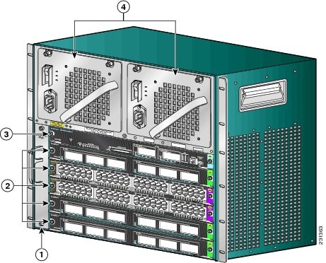
The Catalyst 4507R-E switch is a 7-slot horizontal chassis supporting redundant power supplies, redundant supervisor engines, and slots for up to six modules. Figure 1-3 shows a front view of the Catalyst 4507R-E switch with the chassis major features identified.
Figure 1-3 Catalyst 4507R-E Switch (Front View)
|
|
Fan tray |
|
Supervisor engines (primary in slot 3 and secondary in slot 4) |
|
|
Switching modules (slots 1, 2, 5, 6, 7) |
|
Power supplies |
Table 1-5 describes the features of the Catalyst 4507R-E switch.
Table 1-5 Catalyst 4507R-E Switch Features
|
|
|
Chassis |
Seven horizontal slots. Slots are numbered from 1 (top) to 7 (bottom). |
Supervisor engines |
- Supports the following supervisor engines:
– Supervisor Engine 8L-E 1 – Supervisor Engine 8-E – Supervisor Engine 7L-E – Supervisor Engine 7-E Note Refer to your software release notes for the minimum software release versions required to support the supervisor engines.
- Supervisor engines must be installed in slot 3 and in slot 4.
- Supervisor engine redundancy is supported in this chassis.
Note The Catalyst 4507R-E switch supports 1+1 supervisor-engine redundancy for integrated resiliency. Redundant supervisor engines help minimize network downtime. With the support of stateful switchover (SSO), the secondary supervisor engine serves as a backup to immediately take over after a primary supervisor failure. During the switchover, Layer 2 links are maintained transparently without the need to renegotiate sessions. |
Modules |
- Supports up to five Catalyst 4500 series modules.
- Some Catalyst 4500 series modules may:
– Not be supported – Require that you install a specific supervisor engine – Have chassis slot restrictions – Require a specific software release level to operate
- Check your software release notes for specific support information.
|
Backplane |
24 Gbps full duplex per slot (240 Gbps). |
Fan tray |
- The chassis supports a single hot-swappable fan tray. One fan tray model is available:
– WS-X4597-E Note The Catalyst 4507R-E switch and the Catalyst 4507R+E switch use the same fan tray.
- The fan tray contains eight individual fans. The individual fans are not field replaceable; you must replace the fan tray in the event of a fan failure.
- Air is drawn in on the right side of the chassis and exhausted on the left side of the chassis.
- Fan tray STATUS LED (located on the fan tray front panel)
– Red—One or more individual fans have failed. – Green—Fan tray is operating normally. |
Power supply |
- Supports one or two power supplies. The following power supplies are supported:
– 1000 W AC-input power supply (PWR-C45-1000AC) – 1400 W AC-input power supply (PWR-C45-1400AC) – 1300 W AC-input power supply (PWR-C45-1300ACV) – 2800 W AC-input power supply (PWR-C45-2800ACV) – 4200 W AC-input power supply (PWR-C45-4200ACV) – 6000 W AC-input power supply (PWR-C45-6000ACV) – 9000 W AC-input power supply (PWR-C45-9000ACV) – 1400 W DC-input power supply, triple-input (PWR-C45-1400DC) – 1400 W DC-input power supply with integrated PEM (PWR-C45-1400DC-P) – External AC power shelf (WS-P4502-1PSU)
- All Catalyst 4500 series AC-input power supplies require single-phase source AC.
- Source AC can be out of phase between multiple power supplies or multiple AC-power plugs on the same power supply because all AC power supply inputs are isolated.
- Single power supplies are installed in the left power supply bay. The second power supply is installed in the right power supply bay.
Note For proper operation of the power supply OUTPUT FAIL LED, systems with single power supplies must be configured with a minimum of one fan tray and one supervisor engine. Systems with dual power supplies must have a minimum configuration of one fan tray, one supervisor engine, and one additional module. Failure to meet these minimum configuration requirements can cause a false power supply output fail signal. |
Table 1-6 lists the environmental and physical specifications of the Catalyst 4507R-E switch.
Table 1-6 Catalyst 4507R-E Switch Specifications
|
|
|
Temperature, ambient |
- Operating: 32° to 104°F (0° to 40°C)
- Nonoperating and storage: –40° to 167°F (–40° to 75°C)
|
Humidity (RH), ambient (noncondensing) |
- Operating: 10% to 90%
- Nonoperating and storage: 5% to 95%
|
Altitude,
operating and nonoperating |
–196 to 6561 ft (–60 to 2000 m) |
Sound pressure level |
- One PS: 63.6 dBA at low speed and 68.3 dBA at full speed
- Two PS: 65.4 dBA at low speed and 68.4 dBA at full speed
|
Dimensions (H x W x D) and rack units (RU) |
- 19.19 x 17.31 x 12.50 in. (48.74 x 43.97 x 31.70 cm)
- 11 RU
|
Weight |
- 44.5 lbs (20.19 kg) minimum weight
- 100 lbs (45.4 kg) maximum weight
|
Airflow |
Chassis fan tray: Right to left Power supply fan: Front to back Note We recommend that you maintain a minimum air space of 6 inches (16 cm) between walls and the chassis air vents and a minimum horizontal separation of 12 inches (30.5 cm) between two chassis to prevent overheating. |
Catalyst 4510R-E Switch
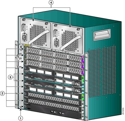
The Catalyst 4510R-E switch is a 10-slot horizontal chassis supporting redundant power supplies, redundant supervisor engines, and slots for up to nine modules. Figure 1-4 shows a front view of the Catalyst 4510R-E switch with the chassis major features identified.
Figure 1-4 Catalyst 4510R-E Switch Chassis (Front View)
|
|
Fan tray assembly |
|
Supervisor engines (primary in slot 5 and secondary in slot 6) |
|
|
Switching modules (slots 1–4 and 7–10) |
|
Power supplies |
Table 1-7 describes the features of the Catalyst 4510R-E switch.
Table 1-7 Catalyst 4510R-E Switch Features
|
|
|
Chassis |
Ten horizontal slots. Slots are numbered from 1 (top) to 10 (bottom). |
Supervisor engines |
- Supports the following supervisor engines:
– Supervisor Engine 8-E – Supervisor Engine 7-E Note Refer to your software release notes for the minimum software release versions required to support the supervisor engines.
- Supervisor engines must be installed in slot 5 or in slot 6.
- Supervisor engine redundancy is supported in this chassis.
Note The Catalyst 4510R-E switch supports 1+1 supervisor-engine redundancy for integrated resiliency. With the support of stateful switchover (SSO), the secondary supervisor engine serves as a backup to immediately take over after a primary supervisor failure. During the switchover, Layer 2 links are maintained transparently without the need to renegotiate sessions. |
Modules |
- Supports up to eight Catalyst 4500 series modules.
- Some Catalyst 4500 series modules may:
– Not be supported – Require that you install a specific supervisor engine – Have chassis slot restrictions – Require a specific software release level to operate
- Check your software release notes for specific support information.
|
Backplane |
24 Gbps full duplex per slot on five slots, plus 12 Gbps full duplex per slot on three slots (276 Gbps) with Supervisor Engine 6-E |
Fan tray |
- The chassis supports one hot-swappable fan tray. One fan tray model is available:
– WS-X4582-E (located on the fan tray front panel) Note The Catalyst 4510R-E and the Catalyst 4510R+E switches use the same fan tray.
- The fan tray contains ten individual fans. The individual fans are not field replaceable; you must replace the fan tray in the event of a fan failure.
- Air is drawn in on the right side of the chassis and exhausted on the left side of the chassis.
- Fan tray STATUS LED (located on the fan tray front panel)
– Red—One or more individual fans have failed. – Green—Fan tray is operating normally. |
Power supply |
- Supports one or two power supplies. The following power supplies are supported:
– 1000 W AC-input power supply (PWR-C45-1000AC) – 1400 W AC-input power supply (PWR-C45-1400AC) – 1300 W AC-input power supply (PWR-C45-1300ACV) – 2800 W AC-input power supply (PWR-C45-2800ACV) – 4200 W AC-input power supply (PWR-C45-4200ACV) – 6000 W AC-input power supply (PWR-C45-6000ACV) – 9000 W AC-input power supply (PWR-C45-9000ACV) – 1400 W DC-input power supply, triple-input (PWR-C45-1400DC) – 1400 W DC-input power supply with integrated PEM (PWR-C45-1400DC-P) – External AC power shelf (WS-P4502-1PSU)
- All Catalyst 4500 series AC-input power supplies require single-phase source AC.
- Source AC can be out of phase between multiple power supplies or multiple AC-power plugs on the same power supply because all AC power supply inputs are isolated.
- Single power supplies are installed in the left power supply bay. The second power supply is installed in the right power supply bay.
Note For proper operation of the power supply OUTPUT FAIL LED, systems with single power supplies must be configured with a minimum of one fan tray and one supervisor engine. Systems with dual power supplies must have a minimum configuration of one fan tray, one supervisor engine, and one additional module. Failure to meet these minimum configuration requirements can cause a false power supply output fail signal. |
Table 1-8 lists the environmental and physical specifications of the Catalyst 4510R-E switch.
Table 1-8 Catalyst 4510R-E Switch Specifications
|
|
|
Temperature, ambient |
- Operating: 32° to 104°F (0° to 40°C)
- Nonoperating and storage: –40° to 167°F (–40° to 75°C)
|
Humidity (RH), ambient (noncondensing) |
- Operating: 10% to 90%
- Nonoperating and storage: 5% to 95%
|
Altitude, operating |
–196 to 6561 ft (–60 to 2000 m) |
Sound pressure level |
- One PS—63.6 dBA at low speed and 68.3 dBA at full speed
- Two PS—65.4 dBA at low speed and 68.4 dBA at full speed
|
Dimensions (H x W x D) and rack units (RU) |
- 24.35 x 17.31 x 12.50 in. (61.84 x 43.97 x 31.70 cm)
- 14 RU
|
Weight |
- 54.5 lbs (24.77 kg) minimum
- 108 lbs (45.4 kg) maximum
|
Airflow |
- Chassis fan tray: Right to left
- Power supply fan: Front to back
Note We recommend that you maintain a minimum air space of 6 inches (16 cm) between walls and the chassis air vents and a minimum horizontal separation of 12 inches (30.5 cm) between two chassis to prevent overheating. |
Catalyst 4507R+E Switch
The Catalyst 4507R+E switch is a 7-slot horizontal chassis supporting redundant power supplies, redundant supervisor engines, and slots for up to five modules. Figure 1-5 shows a front view of the Catalyst 4507R+E switch with the chassis major features identified.
Figure 1-5 Catalyst 4507R+E Switch Chassis
|
|
Fan tray |
|
Supervisor engines (primary in slot 3 and secondary in slot 4) |
|
|
Switching modules (slots 1, 2, 5, 6, 7) |
|
Power supplies |
Table 1-9 describes the features of the Catalyst 4507R+E switch.
Table 1-9 Catalyst 4507R+E Switch Features
|
|
|
Chassis |
Seven horizontal slots. Slots are numbered from 1 (top) to 7 (bottom). |
Supervisor engines |
- Supports the following supervisor engines:
– Supervisor Engine 9-E – Supervisor Engine 8L-E – Supervisor Engine 8-E – Supervisor Engine 7L-E – Supervisor Engine 7-E Note Refer to your software release notes for the minimum software release versions required to support the supervisor engines.
- Supervisor engines must be installed in slot 3 or in slot 4.
- Supervisor engine redundancy is supported in this chassis.
Note The Catalyst 4507R+E switch supports 1+1 supervisor-engine redundancy. With the support of stateful switchover (SSO), the secondary supervisor engine serves as a backup to immediately take over after a primary supervisor failure. During the switchover, Layer 2 links are maintained transparently without the need to renegotiate sessions. |
Modules |
- Supports up to five Catalyst 4500 series modules.
- Some Catalyst 4500 series modules may:
– Not be supported – Require that you install a specific supervisor engine – Have chassis slot restrictions – Require a specific software release level to operate
- Check your software release notes for specific support information.
|
Backplane |
48 Gbps full duplex per slot |
Fan tray |
- The chassis supports a single hot-swappable fan tray. One fan tray model is available:
– WS-X4597+E
- The fan tray contains eight individual fans. The individual fans are not field replaceable; you must replace the fan tray in the event of a fan failure.
- Air is drawn in on the right side of the chassis and exhausted on the left side of the chassis.
- Fan tray STATUS LED (located on the fan tray front panel)
– Red—One or more individual fans have failed. – Green—Fan tray is operating normally. |
Power supply |
- Supports one or two power supplies. The following power supplies are supported:
– 1000 W AC-input power supply (PWR-C45-1000AC) – 1400 W AC-input power supply (PWR-C45-1400AC) – 1300 W AC-input power supply (PWR-C45-1300ACV) – 2800 W AC-input power supply (PWR-C45-2800ACV) – 4200 W AC-input power supply (PWR-C45-4200ACV) – 6000 W AC-input power supply (PWR-C45-6000ACV) – 9000 W AC-input power supply (PWR-C45-9000ACV) – 1400 W DC-input power supply, triple-input (PWR-C45-1400DC) – 1400 W DC-input power supply with integrated PEM (PWR-C45-1400DC-P) – External AC power shelf (WS-P4502-1PSU)
- All Catalyst 4500 series AC-input power supplies require single-phase source AC.
- Source AC can be out of phase between multiple power supplies or multiple AC-power plugs on the same power supply because all AC power supply inputs are isolated.
- Single power supplies are installed in the left power supply bay. The second power supply is installed in the right power supply bay.
Note For proper operation of the power supply OUTPUT FAIL LED, systems with single power supplies must be configured with a minimum of one fan tray and one supervisor engine. Systems with dual power supplies must have a minimum configuration of one fan tray, one supervisor engine, and one additional module. Failure to meet these minimum configuration requirements can cause a false power supply output fail signal. |
Table 1-10 lists the environmental and physical specifications of the Catalyst 4507R+E switch.
Table 1-10 Catalyst 4507R+E Switch Specifications
|
|
|
Temperature, ambient |
- Operating: 32° to 104°F (0° to 40°C)
- Nonoperating and storage: –40° to 167°F (–40° to 75°C)
|
Humidity (RH), ambient (noncondensing) |
- Operating: 10% to 90%
- Nonoperating and storage: 5% to 95%
|
Altitude,
operating and nonoperating |
–196 to 6561 ft (–60 to 2000 m) |
Sound pressure level |
- One PS: 63.6 dBA at low speed and 68.3 dBA at full speed
- Two PS: 65.4 dBA at low speed and 68.4 dBA at full speed
|
Dimensions (H x W x D) and rack units (RU) |
- 19.19 x 17.31 x 12.50 in. (48.74 x 43.97 x 31.70 cm)
- 11 RU
|
Weight |
|
Airflow |
- Chassis fan tray: Right to left
- Power supply fan: Front to back
Note We recommend that you maintain a minimum air space of 6 inches (16 cm) between walls and the chassis air vents and a minimum horizontal separation of 12 inches (30.5 cm) between two chassis to prevent overheating. |
Catalyst 4510R+E Switch
The Catalyst 4510R+E switch is a 10-slot horizontal chassis supporting redundant power supplies, redundant supervisor engines, and slots for up to nine modules. Figure 1-6 shows a front view of the Catalyst 4510R+E switch with the chassis major features identified.
Figure 1-6 Catalyst 4510R+E Switch Chassis (Front View)
|
|
Fan tray |
|
Supervisor engines (primary in slot 5 and secondary in slot 6) |
|
|
Switching modules (slots 1–4, 7–10) |
|
Power supplies |
Table 1-11 describes the features of the Catalyst 4510R+E switch.
Table 1-11 Catalyst 4510R+E Switch Features
|
|
|
Chassis |
Ten horizontal slots. Slots are numbered from 1 (top) to 10 (bottom). |
Supervisor engines |
- Supports the following supervisor engines:
– Supervisor Engine 9-E – Supervisor Engine 8-E – Supervisor Engine 7-E Note Refer to your software release notes for the minimum software release versions required to support the supervisor engines.
- Supervisor engines must be installed in slot 5 or in slot 6.
- Supervisor engine redundancy is supported in this chassis.
Note The Catalyst 4510R+E switch supports 1+1 supervisor engine redundancy for integrated resiliency. With the support of stateful switchover (SSO), the secondary supervisor engine serves as a backup to immediately take over after a primary supervisor failure. During the switchover, Layer 2 links are maintained transparently without the need to renegotiate sessions. |
Modules |
- Supports up to eight Catalyst 4500 series modules.
- Some Catalyst 4500 series modules may:
– Not be supported – Require that you install a specific supervisor engine – Have chassis slot restrictions – Require a specific software release level to operate
- Check your software release notes for specific information.
|
Backplane |
48 Gbps full duplex per slot |
Fan tray |
- The chassis supports a single hot-swappable fan tray. One fan tray model is available:
– WS-X4582+E
- The fan tray contains ten individual fans. The individual fans are not field replaceable; you must replace the fan tray in the event of a fan failure.
- Air is drawn in on the right side of the chassis and exhausted on the left side of the chassis.
- Fan tray STATUS LED (located on the fan tray front panel)
– Red—One or more individual fans have failed. – Green—Fan tray is operating normally. |
Power supply |
- Supports one or two power supplies. The following power supplies are supported:
– 1000 W AC-input power supply (PWR-C45-1000AC) – 1400 W AC-input power supply (PWR-C45-1400AC) – 1300 W AC-input power supply (PWR-C45-1300ACV) – 2800 W AC-input power supply (PWR-C45-2800ACV) – 4200 W AC-input power supply (PWR-C45-4200ACV) – 6000 W AC-input power supply (PWR-C45-6000ACV) – 9000 W AC-input power supply (PWR-C45-9000ACV) – 1400 W DC-input power supply, triple-input (PWR-C45-1400DC) – 1400 W DC-input power supply with integrated PEM (PWR-C45-1400DC-P) – External AC power shelf (WS-P4502-1PSU)
- All Catalyst 4500 series AC-input power supplies require single-phase source AC.
- Source AC can be out of phase between multiple power supplies or multiple AC-power plugs on the same power supply because all AC power supply inputs are isolated.
- Single power supplies are installed in the left power supply bay. The second power supply is installed in the right power supply bay.
Note For proper operation of the power supply OUTPUT FAIL LED, systems with single power supplies must be configured with a minimum of one fan tray and one supervisor engine. Systems with dual power supplies must have a minimum configuration of one fan tray, one supervisor engine, and one additional module. Failure to meet these minimum configuration requirements can cause a false power supply output fail signal. |
Table 1-12 lists the environmental and physical specifications of the Catalyst 4510R+E switch.
Table 1-12 Catalyst 4510R+E Switch Specifications
|
|
|
Temperature, ambient |
- Operating: 32° to 104°F (0° to 40°C)
- Nonoperating and storage: –40° to 167°F (–40° to 75°C)
|
Humidity (RH), ambient (noncondensing) |
- Operating: 10% to 90%
- Nonoperating and storage: 5% to 95%
|
Altitude,
operating and nonoperating |
–196 to 6561 ft (–60 to 2000 m) |
Sound pressure level |
- One PS: 63.6 dBA at low speed and 68.3 dBA at full speed
- Two PS: 65.4 dBA at low speed and 68.4 dBA at full speed
|
Dimensions (H x W x D) and rack units (RU) |
- 24.35 x 17.31 x 12.50 in. (61.84 x 43.97 x 31.70 cm)
- 14 RU
|
Weight |
|
Airflow |
- Chassis fan tray: Right to left
- Power supply fan: Front to back
Note We recommend that you maintain a minimum air space of 6 inches (16 cm) between walls and the chassis air vents and a minimum horizontal separation of 12 inches (30.5 cm) between two chassis to prevent overheating. |


 Feedback