Feedback
Table Of Contents
Connecting the Cisco MDS 9020 Switch
Preparing for Network Connections
Connecting the 10/100 Ethernet Management Port
Connecting to a Fibre Channel Port
Removing and Installing SFP Transceivers
Removing and Installing Cables into SFP Transceivers
Installing a Cable into an SFP Transceiver
Removing a Cable from an SFP Transceiver
Maintaining SFP Transceivers and Fiber Optic Cables
Connecting the Cisco MDS 9020 Switch
The Cisco MDS 9020 Fabric Switch provides the following types of ports:
•
Console port (Interface Module)—An RS-232 port that you can use to create a local management connection.
•
•
This chapter describes how to connect the various components of the Cisco MDS 9020 Fabric Switch, and it includes the following information:
•
•
•
Preparing for Network Connections
When preparing your site for network connections to the Cisco MDS 9020 Fabric Switch, consider the following for each type of interface:
•
•
•
Before installing the component, have all additional external equipment and cables available.
Connecting the Console Port
This section describes how to connect the RS-232 console port to a PC. The console port allows you to perform the following functions:
•
•
•
•
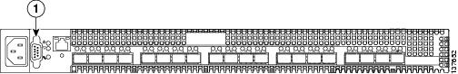
The console port, located on the front panel, is shown in Figure 3-1.
Figure 3-1 Console Port
For local administrative access to the Cisco MDS 9020 Fabric Switch, you can connect the PC serial port to the switch console port with the console cable included with the switch. The console cable, or roll over cable, is a null-modem DB9 cable.
Note
To connect the console port to a PC, follow these steps:
Step 1
•
•
•
•
•
Step 2
Connecting the 10/100 Ethernet Management Port
The autosensing 10/100 Ethernet management port is located on the left side of the front panel, to the right of the console port. This port is used for out-of-band management of the Cisco MDS 9020 Fabric Switches. Use modular, RJ-45, straight-through UTP cables to connect the 10/100 Ethernet management port to external hubs, switches, and routers. The default IP address is 10.0.0.1.
Connecting to a Fibre Channel Port
The Fibre Channel ports are compatible with LC-type fiber-optic SFP transceivers and cables. The Cisco MDS 9020 Fabric Switch supports the Fibre Channel protocol for SFP transceivers. Each transceiver must match the transceiver on the other end of the cable, and the cable must not exceed the stipulated cable length for reliable communications. Refer to the Release Notes for Cisco MDS 9020 Fabric Switch for FabricWare Release 2.1(2) for the list of specific supported SFP transceivers. SFP transceivers can be ordered separately or with the Cisco MDS 9020 Fabric Switch.
Warning
Warning
Caution
This section provides the following information:
•
•
•
Removing and Installing SFP Transceivers
Caution
Note
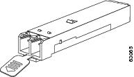
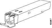
The Cisco MDS 9020 Fabric Switch supports SFP transceivers with the following two types of latching devices:
· Mylar tab latch (Figure 3-2)
· Bale-clasp latch (Figure 3-3)
Figure 3-2 SFP Transceiver with Mylar Tab Latch
Figure 3-3 SFP Transceiver with Bale-Clasp Latch
Installing an SFP Transceiver
To install an SFP transceiver, follow these steps:
Step 1
Caution
Step 2
Step 3
Step 4
•
•
Step 5
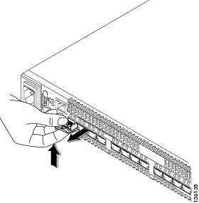
Removing an SFP Transceiver
To remove an SFP transceiver, follow these steps:
Step 1
Step 2
a.
b.
c.
d.
Tip
Step 3
•
•
Note
Figure 3-4 Alternate Removal Method for Bale Clasp SFP Transceivers
Step 4
Step 5
Removing and Installing Cables into SFP Transceivers
Caution
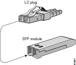
Installing a Cable into an SFP Transceiver
Caution
To install a cable into a transceiver, follow these steps:
Step 1
Step 2
Step 3
Step 4
Figure 3-5 Connecting the LC-Type Cable to a Fibre Channel Port
Caution
For instructions on verifying connectivity, refer to the Cisco MDS 9020 Fabric Switch Configuration Guide and Command Reference.
Removing a Cable from an SFP Transceiver
Caution
Caution
To remove the cable, follow these steps:
Step 1
Step 2
Step 3
Step 4
Maintaining SFP Transceivers and Fiber Optic Cables
SFP transceivers and fiber optic cables must be kept clean and dust-free to maintain high signal accuracy and prevent damage to the connectors. Attenuation (loss of light) is increased by contamination, and should be kept below 0.35 dB.
Maintenance guidelines:
•
•
•
•
•
•