Feedback
Table Of Contents
Installing the Cisco MDS 9020 Fabric Switch
Unpacking and Inspecting the Switch
Installing the Switch in a Cabinet or Rack
Installing the Rack-Mount Brackets
Installing the Cisco MDS 9020 Fabric Switch
This chapter describes how to install the Cisco MDS 9020 Fabric Switch and its components, and it includes the following information:
•
Installing the Switch in a Cabinet or Rack
Note
Warning
This warning symbol means danger. You are in a situation that could cause bodily injury. Before you work on any equipment, be aware of the hazards involved with electrical circuitry and be familiar with standard practices for preventing accidents. Use the statement number provided at the end of each warning to locate its translation in the translated safety warnings that accompanied this device. Statement 1071
SAVE THESE INSTRUCTIONS
Warning
Pre-Installation
This section provides the following information:
•
Installation Options
The Cisco MDS 9020 Fabric can be installed using the following methods:
•
–
–
•
–
–
•
–
For instructions on installing the switch using the rack-mount kit shipped with the switch, see the"Installing the Switch in a Cabinet or Rack" section.
For instructions on installing the switch using the optional, separately purchased rack-mount kit, see the "Cabinet and Rack Installation."
Note
Installation Guidelines
Follow these guidelines when installing the Cisco MDS 9020 Fabric Switch:
•
•
•
•
Note
Note
•
•
Caution
•
Caution
•
–
–
–
–
–
Required Equipment
Gather the following tools before beginning the installation:
•
•
•
•
•
Unpacking and Inspecting the Switch
Caution
Tip
Note
Note
To inspect the shipment, following these steps:
Step 1
Step 2
•
•
•
•
Installing the Switch in a Cabinet or Rack
This section describes how to install the Cisco MDS 9020 Fabric Switch. You can install the switch in a rack using the rack-mount brackets alone, or you can use the rack-mount kit.
Note
Required Equipment
•
•
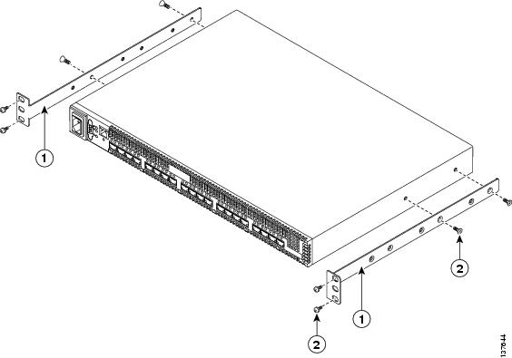
Installing the Rack-Mount Brackets
To mount the switch in a rack using just the rack-mount brackets, follow these steps:
Step 1
Step 2
Figure 2-1 Installing the Rack-Mount Brackets
Installing the Rack-Mount Kit
Installing a switch in a rack or cabinet using the rack-mount kit involves installing switch slides on the switch and installing the shelf brackets in the rack or cabinet.
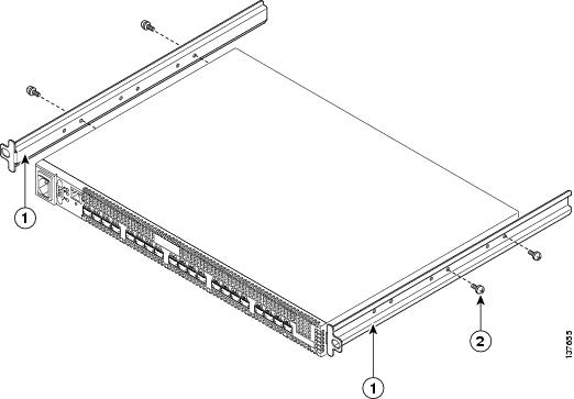
Installing the Switch Slides
Figure 2-2 shows the installation of the switch slides on the switch. The switch slides have several holes to allow you to mount the switch flush with the cabinet or with a setback.
Figure 2-2 Installing the Switch Slides on the Switch
To install the switch slides on the switch, follow these steps:
Step 1
Step 2
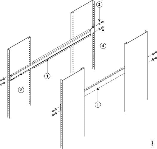
Installing the Shelf Brackets
Figure 2-3 shows the installation of the shelf brackets in a four-post EIA rack.
Figure 2-3 Installing the Shelf Brackets in an EIA Rack
To install the shelf and slider bracket assemblies in the rack, follow these steps:
Step 1
Step 2
Step 3
Step 4
Grounding the Switch
The switch is grounded through its power cord when connected to an AC power source. Furthermore, the switch is grounded to the rack through the rack-mount kit. No other grounding is required.
Starting Up the Switch
This section provides instructions for powering up the switch and verifying component installation.
Caution
Note
To power up the switch and verify hardware operation, follow these steps:
Step 1
Note
Step 2
Step 3
Step 4
Step 5
•
•
•
Note