Feedback
Table Of Contents
Cisco Fibre Channel SFP Transceiver Specifications
General Specifications for Cisco Fibre Channel SFP Transceivers
Environmental and Electrical Specifications for Cisco Fibre Channel SFP Transceivers
Cable and Port Specifications
This appendix describes the cables and connectors used with the Cisco MDS 9020 Fabric Switch, and it includes the following information:
•
Cisco Fibre Channel SFP Transceiver Specifications
Caution
Cables and Adapters Provided
The accessory kit includes a null modem DB-9 cable.
Note
Note
Console Port
The console port is an asynchronous RS-232 serial port. Use a null-modem DB9 cable to connect the console port to a computer running terminal emulation software.
Table D-1 lists the pinouts for the console port on the Cisco MDS 9020 Fabric Switch.
Table D-1 Console Port Pinout
11
Carrier Detect (DCD)
2
Receive Data (RxD)
3
Transmit Data (TxD)
4
Data Terminal Ready (DTR)
5
Signal Ground (GND)
6
Data Set Ready (DSR)
7
Request to Send (RTS)
8
Clear to Send (CTS)
9
Ring Indicator (RI)
1 Pin 1 is internally connected to pin 6.
MGMT 10/100 Ethernet Port
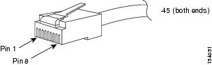
Use a modular, RJ-45, straight-through UTP cable to connect the 10/100 management Ethernet port to external hubs and switches. To connect to a router or directly to a workstation, use a crossover cable. (See Figure D-1.)
Figure D-1 RJ-45 Interface Cable Connector
Table D-2 lists the connector pinouts and signal names for a 10/100BASE-T management port (MDI) cable.
Table D-2 10/100 BASE-T Management Port Cable Pinout (MDI)
1
TD+
2
TD-
3
RD+
6
RD-
4
Not used
5
Not used
7
Not used
8
Not used
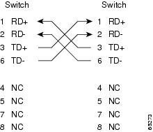
Figure D-2 shows a schematic of the 10/100BASE-T cable.
Figure D-2 Twisted-Pair 10/100BASE-T Cable Schematic
Cisco Fibre Channel SFP Transceiver Specifications
The Cisco MDS 9020 Fabric Switch is compatible with SFP transceivers and cables that have LC connectors. Each transceiver must match the transceiver on the other end of the cable in terms of wavelength, and the cable must not exceed the stipulated cable length for reliable communications.
Cisco SFP transceivers provide the uplink interfaces, laser send (TX), and laser receive (RX), and support 850 to 1610 nm nominal wavelengths, depending upon the transceiver.
Use only Cisco SFP transceivers on the Cisco MDS 9020 Fabric Switch. Each Cisco SFP transceiver is encoded with model information that enables the switch to verify that the SFP transceiver meets the requirements for the switch. Refer to the release notes for the list of specific supported SFP transceivers.
For information about Safety, Regulatory, and Standards Compliance, refer to the Regulatory Compliance and Safety Information for the Cisco MDS 9000 Family Switch.
Table D-3 lists the Fibre Channel SFP transceivers available through Cisco.
General Specifications for Cisco Fibre Channel SFP Transceivers
Table D-4 lists general specifications for Cisco Fibre Channel SFP transceivers.
Table D-4 General Specifications for Cisco Fibre Channel SFP Transceivers
Connector type
LC
LC
Wavelength
850 nm
1310 nm
Fiber type
MMF
SMF
Core size
50 microns
62.5 microns
9/125 microns
Cable distance (max)1
500 m @ 1 Gbps
300 m @ 2 Gbps
175 m @ 4 Gbps300 m @ 1 Gbps
150 m @ 2 Gbps
70 m @ 4 Gbps2 km @ 1 Gbps
2 km @ 2 Gbps
10 km @ 4 GbpsTransmit power
-10 to -1.5 dBm
-9.5 to -3 dBm
1 Approximate; actual distance may vary depending on fiber quality and other factors.
Environmental and Electrical Specifications for Cisco Fibre Channel SFP Transceivers
Table D-5 provides the maximum environmental and electrical ratings for Cisco Fibre Channel SFP transceivers.
Notes:
1.
2.