Feedback
Table Of Contents
Power-On Self Test Diagnostics
Internal Firmware Failure Blink Pattern
Configuration File System Error Blink Pattern
Over Temperature Blink Pattern
Recovering a Switch Using Maintenance Mode
Unpacking Firmware Image Files
Resetting the Network Configuration
Restoring the Default User Accounts
Removing the Switch Configuration
Troubleshooting
This appendix describes how to troubleshoot the Cisco MDS 9020 Fabric hardware installation, and it includes the following information:
General System Checks
Problems with the initial power up are often caused by a switch that has been disconnected from the power cord connector. When the initial system boot is complete, verify that:
•
The switch is installed correctly and it initializes without problems. Refer to "Installing the Cisco MDS 9020 Fabric Switch."
•
Troubleshooting Components
Diagnostic information about the switch is available through the chassis LEDs and the port LEDs. This section describes the following types of diagnostics:
•
This section also describes how to use maintenance mode to recover a disabled switch.
Switch Diagnostics
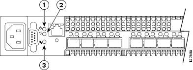
Switch diagnostics are indicated by the switch LEDs as shown in Figure B-1.
Figure B-1 Switch LEDs
The following conditions are described:
Input Power LED Is Off
The Input Power LED indicates that the switch logic circuitry is receiving proper voltages. If the Input Power LED is off, follow these steps:
Step 1
•
•
Step 2
•
•
System Fault LED Is On
The System Fault LED indicates that the switch logic circuitry is overheating or that a POST error has occurred. The System Fault LED is always accompanied by a Heartbeat LED error blink code. If the System Fault LED is on, then identify the Heartbeat LED error blink pattern and take the necessary actions. See the "Power-On Self Test Diagnostics" section for more information about Heartbeat LED blink patterns.
Power-On Self Test Diagnostics
The switch performs a series of tests as part of its power-up procedure. The POST diagnostic program performs the following tests:
•
•
•
During the POST, the switch logs any errors encountered. Some POST errors are critical, others are not. The switch uses the Heartbeat LED and the Logged-In LED to indicate switch and port status. A critical error disables the switch so that it will not operate. A non-critical error allows the switch to operate, but disables the ports that have errors. Whether the problem is critical or not, contact your authorized maintenance provider.
If there are no errors, the Heartbeat LED blinks at a steady rate of once per second. If a critical error occurs, the Heartbeat LED will show an error blink pattern and the System Fault LED will be on. If there are non-critical errors, the switch disables the failed ports and flashes the associated Logged-In LEDs.
The Heartbeat LED indicates the operational status of the switch. When the POST completes with no errors, the Heartbeat LED blinks at a steady rate of once per second. When the switch is in maintenance mode, the Heartbeat LED is on continuously. See the "Recovering a Switch Using Maintenance Mode" section for more information about maintenance mode. All other blink patterns indicate critical errors. In addition to producing Heartbeat error blink patterns, a critical error also turns on the System Fault LED.
The Heartbeat LED shows an error blink pattern for the following conditions:
•
•
•
•
Internal Firmware Failure Blink Pattern
An internal firmware failure blink pattern is two blinks followed by a two-second pause. The two-blink error pattern indicates that the firmware has failed, and that the switch must be reset. Momentarily press and release the Maintenance button to reset the switch.
System Error Blink Pattern
A system error blink pattern is three blinks followed by a two-second pause. The three-blink error pattern indicates that a POST failure or a system error has left the switch inoperable. If a system error occurs, contact your authorized maintenance provider. Momentarily press and release the Maintenance button to reset the switch.
Configuration File System Error Blink Pattern
A configuration file system error blink pattern is four blinks followed by a two-second pause. The four-blink error pattern indicates that a file system error has occurred, and that the file system must be recreated. To recreate the file system, see "Remaking the Filesystem" section.
Over Temperature Blink Pattern
An over temperature blink pattern is five blinks followed by a two-second pause. The five-blink error pattern indicates that the air temperature inside the switch has exceeded the failure temperature threshold. The failure temperature threshold is 70° C (158 ° F).
If the Heartbeat LED shows the over temperature blink pattern, follow these steps:
Step 1
•
•
Step 2
Logged-In LED Indications
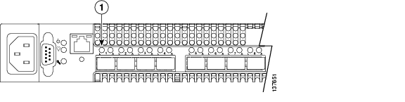
Port diagnostics are indicated by the Logged-In LED for each port. Figure B-2 identifies the Logged-In LED for port 1.
Figure B-2 Fibre Channel Port LEDs
The Logged-In LED has three indications:
•
•
•
If a Logged-In LED is off, review the logfile for messages regarding the affected port. A Logged-In LED error indication is often the result of E Port isolation. E Port isolation can be caused by the following:
•
•
•
•
Refer to the Cisco MDS 9020 Fabric Switch Configuration Guide and Command Reference for information about how to change domain IDs, timeout values, and zoning.
To diagnose an isolated E Port, follow these steps:
Step 1
•
•
Step 2
•
•
Step 3
•
•
Step 4
•
•
Recovering a Switch Using Maintenance Mode
A switch can become inoperable or unmanageable for the following reasons:
•
•
•
•
In these specific cases, you can recover the switch using maintenance mode. Maintenance mode temporarily returns the switch IP address to 10.0.0.1 and provides opportunities to do the following:
•
•
•
•
•
•
To recover a switch, follow these steps:
Step 1
Step 2
Step 3
Step 4
Switch login: prom
Password:xxxx
Step 5
0)  Exit
1)  Image Unpack
2)  Reset Network Config
3)  Reset User Accounts to Default
4)  Copy Log Files
5)  Remove Switch Config
6)  Remake Filesystem
7)  Reset Switch
8)  Update Boot Loader
Option:
Step 6
The maintenance menu options are described in the following sections:
•
•
•
•
Exiting Maintenance Mode
This option closes the current login session. To log in again, enter the maintenance mode account name and password (prom, prom). To return to normal operation, select option 7 for Reset Switch from the Maintenance menu.
Unpacking Firmware Image Files
This option is not applicable to the Cisco MDS 9020 Fabric Switch.
Resetting the Network Configuration
The Reset Network Config option resets the network properties to the factory default values and disables the mgmt0 interface. The network default values are as follows:
•
•
•
Restoring the Default User Accounts
The Reset User Accounts to Default option restores the password for the Admin account name to the default (admin123) and removes all other user accounts from the switch.
Copying Log Files
This option is not applicable to the Cisco MDS 9020 Fabric Switch.
Removing the Switch Configuration
The Remove Switch Config option deletes all configurations from the switch except the default configuration. This restores switch configuration parameters to the factory defaults except for user accounts and zoning.
Note
Remaking the Filesystem
In the event the switch configuration becomes corrupt, the file system on which the configuration is stored must be recreated. The Remake Filesystem option recreates the file system and resets the switch to the factory default values including user accounts and zoning.
Caution
To recreate the file system, follow these steps:
Step 1
Step 2
Step 3
Step 4
Switch login: promPassword:xxxxStep 5
0) Exit1) Image Unpack2) Reset Network Config3) Reset User Accounts to Default4) Copy Log Files5) Remove Switch Config6) Remake Filesystem7) Reset Switch8) Update Boot LoaderOption: 6Step 6
Resetting the Switch
The Reset Switch option closes the Telnet session, exits maintenance mode, and reboots the switch using the current switch configuration.
Updating the Boot Loader
The Update Boot Loader option updates the system boot loader, which loads the Linux kernel into memory.
Note
Identifying Startup Problems
LEDs indicate all system states in the startup sequence. By checking the LEDs, you can determine when and where the system failed in the startup sequence.
To identify startup problems, follow these steps:
Step 1
Step 2
•
•
•
If the Input Power LED is off, see the "Input Power LED Is Off" section for troubleshooting procedures.
If the System Fault LED is on, the Heartbeat LED will show an error blink pattern. See the "Power-On Self Test Diagnostics" section for blink pattern descriptions and remedies.
Step 3
Contacting Customer Service
If you are unable to solve a startup problem after using the troubleshooting suggestions in this appendix, contact a customer service representative for assistance and further instructions. Before you call, have the following information ready to help your service provider assist you as quickly as possible:
•
•
Note
•
•
•
•
After you have collected this information, see the "Obtaining Technical Assistance" section.