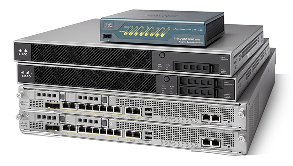
Cisco ASA 5500-X Series Firewalls
| Product Type | Firewalls |
|---|---|
| Status |
End of Support
EOL Details
|
| Series Release Date | 03-MAY-2005 |
| End-of-Sale Date | 04-SEP-2020 |
| End-of-Support Date | 30-SEP-2025 |
| Diagram | Visio Stencil (7 MB .zip file) |
|
This product is no longer supported by Cisco.
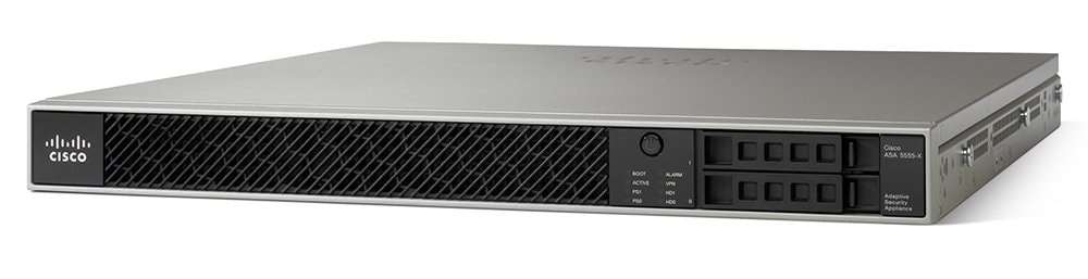
Retired Models: - Cisco ASA 5525-X Adaptive Security Appliance - Cisco ASA 5545-X Adaptive Security Appliance - Cisco ASA 5555-X Adaptive Security Appliance |
|
- US/Canada 800-553-2447
- Worldwide Support Phone Numbers
- All Tools
 Feedback
 Feedback
-
Log in to see full product documentation.
-
Data Sheets and Product Information
- Cisco ASA 5500 Series Adaptive Security Appliances Data Sheet
- Cisco ASA 5500 and ASA 5500-X Series Next Generation Firewalls for the Internet Edge Data Sheet
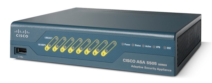
- Cisco ASA 5505 Adaptive Security Appliance for Small Office or Branch Locations Data Sheet
- Cisco ASA 5500 Series Advanced Inspection and Prevention Security Services Module and Card
- Cisco ASA 5500 Series Unified Communications Deployments
- Cisco ASA 5500 Series Content Security and Control Security Services Module
Data Sheets
-
English
- End-of-Sale and End-of-Life Announcement for the Cisco ASA5508 and ASA5516 Series Security Appliance 1 YR Subscriptions
- End-of-Sale and End-of-Life Announcement for the Cisco ASA5525, ASA5545 & ASA5555 Series 3 YR Subscriptions
- End-of-Sale and End-of-Life Announcement for the Cisco Context Directory Agent (CDA)
- End-of-Sale and End-of-Life Announcement for the Cisco ASA CX Context-Aware Security and Cisco Prime Security Manager
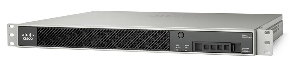
- End-of-Sale and End-of-Life Announcement for the Cisco ASA 5512-X and ASA 5515-X
- End-of-Sale and End-of-Life Announcement for the Cisco ASA 5585-X Adaptive Security Appliance
- End-of-Sale and End-of-Life Announcement for the Cisco ASA 5505 Adaptive Security Appliance
- End-of-Sale and End-of-Life Announcement for the Cisco ASA 1000V
- EOL/EOS for the Cisco ASA 5580 Adaptive Security Appliance
- End-of-Sale and End-of-Life Announcement for the Cisco ASA 5550 Adaptive Security Appliances
- End-of-Sale and End-of-Life Announcement for the Cisco ASA 5520 Adaptive Security Appliance
- End-of-Sale and End-of-Life Announcement for the Cisco ASA 5510 Adaptive Security Appliance
- End-of-Sale and End-of-Life Announcement for the Cisco ASA 5540 Adaptive Security Appliances
End-of-Life and End-of-Sale Notices
Log in to see available downloads.
-