-
Dial Configuration Guide, Cisco IOS Release 15M&T
- Part 1: Dial Interfaces, Controllers, and Lines
-
Part 2: Modem Configuration and Management
-
Overview of Modem Interfaces
-
Configuring and Managing Integrated Modems
-
1- and 2-Port V.90 Modem WICs for Cisco 2600 and Cisco 3600 Series Multiservice Platforms
-
Call Tracker show Commands Extensions
-
Cisco NM-8AM-V2 and NM-16AM-V2 Analog Modem Network Modules with V.92
-
MICA and NextPort Modem Tech-Support Command Additions
-
PIAFS Wireless Data Protocol Version 2.1 for Cisco MICA Modems
-
V.92 and V.44 Support for Digital Modems
-
V.92 Modem on Hold for Cisco AS5300 and Cisco AS5800 Universal Access Servers
-
V.92 Modem on Hold for Cisco AS5350, Cisco AS5400, and Cisco AS5850 Universal Gateways and Cisco AS5800 Universal Access Servers
-
V.92 Quick Connect for Cisco AS5300 and Cisco AS5800 Universal Access Servers
-
V.92 Quick Connect for Cisco AS5350, Cisco AS5400, and Cisco AS5850 Universal Gateways and Cisco AS5800 Universal Access Servers
-
V.92 Reporting Using RADIUS Attribute v.92-info
-
Configuring and Managing Cisco Access Servers and Dial Shelves
-
Configuring and Managing External Modems
-
Modem Signal and Line States
-
Creating and Using Modem Chat Scripts
-
Cisco Modem User Interface
-
Modem Script and System Script Support in Large-Scale Dial-Out
-
-
Part 3: ISDN Configuration
-
Configuring ISDN BRI
-
Leased and Switched BRI Interface for ETSI NET3
-
ISDN BCAC and Round-Robin Channel Selection Enhancements
-
Configuring Virtual Asynchronous Traffic over ISDN
-
Configuring Modem Use over ISDN BRI
-
Configuring X.25 on ISDN
-
Configuring X.25 on ISDN Using AO/DI
-
Configuring ISDN on Cisco 800 Series Routers
-
- Part 4: Signaling Configuration
-
Part 5: Dial-on-Demand Routing Configuration
-
Preparing to Configure DDR
-
Configuring Legacy DDR Spokes
-
Configuring Legacy DDR Hubs
-
Configuring Peer-to-Peer DDR with Dialer Profiles
-
Dialer Map VRF-Aware for an MPLS VPN
-
Dialer Persistent
-
PPPoE Client DDR Idle-Timer
-
Redial Enhancements
-
Rotating Through Dial Strings
-
Configuring Dialer CEF
-
CEF Support for Dialer Profiles on Cisco 7500 Routers
-
IPv6 Cisco Express Forwarding Switching on Dialer Interfaces
-
Configuring Snapshot Routing
-
- Part 6: Dial-Backup Configuration
- Part 7: Dial-Related Addressing Services
- Part 8: Virtual Templates and Profiles
-
Part 9: PPP Configuration
-
Configuring Asynchronous SLIP and PPP
-
Optimized PPP Negotiation
-
Customer Profile Idle Timer Enhancements for Interesting Traffic
-
Multilink PPP Minimum Links Mandatory
-
Configuring Media-Independent PPP and Multilink PPP
-
PPP/MLP MRRU Negotiation Configuration
-
Troubleshooting Enhancements for Multilink PPP over ATM Link Fragmentation and Interleaving
-
Multichassis Multilink PPP
-
- Part 10: Callback and Bandwidth Allocation Configuration
- Configuring Large-Scale Dial-Out
- Part 11: Dial Access Specialized Features
- Part 12: Dial Access Scenarios
 Feedback
Table Of Contents
Related Features and Technologies
Supported Standards, MIBs, and RFCs
Configuring the LNS to Request Dial-Out
Configuring a LAC to Accept Dial-Out
Verifying L2TP Large-Scale Dial-Out
Monitoring and Maintaining L2TP Large-Scale Dial-Out
LNS Configured to Request Dial-Out Example
LAC Configured to Accept Dial-Out Example
L2TP Large-Scale Dial-Out
Feature History
12.2(4)T
This feature was introduced.
12.2(11)T
This feature was implemented on Cisco access server platforms.
This document describes the L2TP Large-Scale Dial-Out feature. It includes the following sections:
•
Supported Standards, MIBs, and RFCs
•
Feature Overview
The Asynchronous Line Monitoring feature feature enables the router to dial multiple Layer 2 Tunnel Protocol (L2TP) access concentrators (LACs) from a single L2TP network server (LNS). The LACs are signaled through the LNS and use L2TP to establish the dial sessions. User-defined profiles can be configured on an authentication, authorization, and accounting (AAA) server and retrieved by the LNS when dial-out occurs.The Asynchronous Line Monitoring feature feature also supports multiple LACs bound into one stack group, call traffic load balancing, and outbound call congestion management.
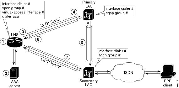
Figure 1 provides an example of L2TP large-scale dial-out session startup. Each part of the process is numbered and described in text following the figure.
Figure 1 Sample Scenario L2TP Large-Scale Dial-Out Session
1.
2.
3.
4.
5.
After the secondary LAC receives the SGBP Discover message from the LNS, it responds with an SGBP Offer message describing available resources.
6.
If the secondary LAC has more resources, the primary LAC can choose to dial through the secondary LAC. The primary LAC sends a CDN message to the LNS with error code 7, which means "Try another" as defined in RFC 2661. Inside this message, the LNS learns that its dial-out request should be redirected to the secondary LAC, and the LNS clears the session to the primary LAC.
7.
Benefits
Large-Scale Dial-Out Integrated with L2TP
Before Cisco IOS Release 12.2(4)T, L2TP required that requests for tunneled dial-out calls be from a single LNS to a single LAC, and that configurations be available on the local server. The Asynchronous Line Monitoring feature feature introduced in Cisco IOS Release 12.2(4)T allows dialing multiple LACs from a single LNS. The LACs are signaled through the LNS using L2TP to establish the dial sessions. User-defined profiles can also be configured on a AAA server and retrieved by the LNS when dial-out occurs.
Enhanced Dial Management
The Asynchronous Line Monitoring feature feature also provides the following benefits:
•
•
•
Related Features and Technologies
L2TP, VPDNs, and large-scale dial-out are described in the Cisco IOS Dial Technologies Configuration Guide, Release 12.2. Refer to the chapter "Configuring Virtual Private Networks" in the part "Virtual Templates, Profiles, and Networks," and the chapter "Configuring Large-Scale Dial-Out" in the part "Dial Access Specialized Features."
Supported Platforms
See the next section for information about Feature Navigator and how to use this tool to determine the platforms and software images in which this feature is available.
Platform Support Through Feature Navigator
Cisco IOS software is packaged in feature sets that support specific platforms. To get updated information regarding platform support for this feature, access Feature Navigator. Feature Navigator dynamically updates the list of supported platforms as new platform support is added for the feature.
Feature Navigator is a web-based tool that enables you to quickly determine which Cisco IOS software images support a specific set of features and which features are supported in a specific Cisco IOS image.
To access Feature Navigator, you must have an account on Cisco.com. If you have forgotten or lost your account information, send a blank e-mail to cco-locksmith@cisco.com. An automatic check will verify that your e-mail address is registered with Cisco.com. If the check is successful, account details with a new random password will be e-mailed to you. Qualified users can establish an account on Cisco.com by following the directions at http://www.cisco.com/register.
Feature Navigator is updated when major Cisco IOS software releases and technology releases occur. As of May 2001, Feature Navigator supports M, T, E, S, and ST releases. You can access Feature Navigator at the following URL:
http://www.cisco.com/go/fn
Supported Standards, MIBs, and RFCs
Standards
None
MIBs
None
To obtain lists of supported MIBs by platform and Cisco IOS release, and to download MIB modules, go to the Cisco MIB website on Cisco.com at the following URL:
http://www.cisco.com/public/sw-center/netmgmt/cmtk/mibs.shtml
RFCs
•
Configuration Tasks
See the following sections for configuration tasks for the Asynchronous Line Monitoring feature feature. Each task in the list is identified as either required or optional:
•
•
Configuring the LNS to Request Dial-Out
Virtual profiles depend on PPP authentication; therefore the LNS must authenticate the connection to use virtual profiles.
You must configure AAA network security services on the LNS. For more information about AAA, refer to the chapter "AAA Overview" in the Cisco IOS Security Configuration Guide, Release 12.2. The Cisco IOS Security Command Reference, Release 12.2, describes the commands to configure AAA.
You also need to configure your LNS to communicate with the applicable security server, either a TACACS+ or RADIUS daemon.
If you are using RADIUS and Ascend attributes, use the radius-server host non-standard global configuration command to enable your Cisco router, acting as a network access server, to recognize that the RADIUS security server is using a vendor-proprietary version of RADIUS. Use the radius-server key global configuration command to specify the shared secret text string used between your Cisco router and the RADIUS server. For more information, refer to the chapter "Configuring RADIUS" in the Cisco IOS Security Configuration Guide, Release 12.2.
If you are using TACACS+, use the tacacs-server host global configuration command to specify the IP address of one or more TACACS+ daemons. Use the tacacs-server key global configuration command to specify the shared secret text string used between your Cisco router and the TACACS+ daemon. For more information, see the Cisco IOS Security Configuration Guide, Release 12.2.
To configure the LNS to request dial-out tunneled PPP connections from a LAC, use the following commands beginning in global configuration mode:
The MLP feature provides load-balancing functionality over multiple WAN links and offers load calculation on both inbound and outbound traffic. Refer to the part "PPP Configuration" and the chapter "Configuring Media-Independent PPP and Multilink PPP" in the Cisco IOS Dial Technologies Configuration Guide, Release 12.2, for more information.
See the configuration examples later in this document for additional commands that may be configured on the LAC.
Configuring a LAC to Accept Dial-Out
You must configure SGBP to allow a primary LAC that is congested or otherwise unable to dial out to select an alternate LAC to dial out. Configure SGBP using the sgbp group and sgbp member global configuration commands before enabling the stack group to bid for dial-out connection. Configuring SGBP is described in the chapter "Configuring Multichassis Multilink PPP" in the Cisco IOS Dial Technologies Configuration Guide, Release 12.2. The Cisco IOS Dial Technologies Command Reference, Release 12.2, describes the commands to configure a stack group.
Additionally, the information about configuring network security in the section "Configuring the LNS to Request Dial-Out" of this document also applies to configuring the LAC.
To configure a LAC to accept tunneled dial-out connections from the LNS, use the following commands beginning in global configuration mode:
See the configuration examples later in this document for additional commands that may be configured on the LAC.
Verifying L2TP Large-Scale Dial-Out
To verify that L2TP large-scale dial-out is configured correctly, perform the following steps:
Note
Step 1
Router# show vpdnL2TP Tunnel and Session Information Total tunnels 1 sessions 1LocID RemID Remote Name State Remote Address Port Sessions55788 55043 rdt5300-15 est 10.23.1.1 1701 1LocID RemID TunID Intf Username State Last ChgFastswitch83 50 55788 Vi1 rdt7204-1 est 00:01:08enabled%No active L2F tunnels%No active PPTP tunnels%No active PPPoE tunnelsRouter# show vpdn tunnel allL2TP Tunnel Information Total tunnels 1 sessions 1Tunnel id 8873 is up, remote id is 41736, 1 active sessionsTunnel state is established, time since change 00:00:05Remote tunnel name is rdt5300-15Internet Address 10.23.1.1, port 1701Local tunnel name is rdt7206vxr-8Internet Address 10.23.1.100, port 170111 packets sent, 12 received653 bytes sent, 666 receivedControl Ns 3, Nr 3Local RWS 10000 (default), Remote RWS 800Tunnel PMTU checking disabledRetransmission time 1, max 1 secondsUnsent queuesize 0, max 0Resend queuesize 0, max 2Total resends 0, ZLB ACKs sent 2Current nosession queue check 0 of 5Retransmit time distribution: 0 2 0 0 0 0 0 0 0Sessions disconnected due to lack of resources 0%No active L2F tunnels%No active PPTP tunnels%No active PPPoE tunnelsStep 2
Router# show interfaces virtual-access 1Virtual-Access1 is up, line protocol is upHardware is Virtual Access interfaceMTU 1500 bytes, BW 64 Kbit, DLY 100000 usec,reliability 255/255, txload 1/255, rxload 1/255Encapsulation PPP, loopback not setDTR is pulsed for 5 seconds on resetTime to interface disconnect: idle 00:01:16Interface is bound to Di1 (Encapsulation PPP)LCP Open, multilink OpenOpen: IPCP, CDPCPLast input 00:00:07, output never, output hang neverLast clearing of "show interface" counters 00:01:33Input queue: 0/75/0/0 (size/max/drops/flushes); Total output drops: 0Queueing strategy: weighted fairOutput queue: 0/1000/64/0 (size/max total/threshold/drops)Conversations 0/1/16 (active/max active/max total)Reserved Conversations 0/0 (allocated/max allocated)Available Bandwidth 48 kilobits/sec5 minute input rate 0 bits/sec, 0 packets/sec5 minute output rate 0 bits/sec, 0 packets/sec9 packets input, 767 bytes, 0 no bufferReceived 0 broadcasts, 0 runts, 0 giants, 0 throttles0 input errors, 0 CRC, 0 frame, 0 overrun, 0 ignored, 0 abort10 packets output, 849 bytes, 0 underruns0 output errors, 0 collisions, 0 interface resets0 output buffer failures, 0 output buffers swapped out0 carrier transitionsStep 3
Router# show ppp multilinkVirtual-Access3, bundle name is rdt7204-1Bundle up for 00:01:19Using relaxed lost fragment detection algorithm.Dialer interface is Dialer10 lost fragments, 0 reordered, 0 unassigned0 discarded, 0 lost received, 1/255 load0x8 received sequence, 0x8 sent sequenceMember links: 4 (max not set, min not set)rdt5300-15:Virtual-Access1 (10.23.1.1), since 00:01:19, last rcvd seq000006, unsequencedrdt5300-15:Virtual-Access5 (10.23.1.1), since 00:01:18, last rcvd seq000007, unsequencedrdt5300-15:Virtual-Access4 (10.23.1.1), since 00:00:48, no frags rcvd,unsequencedrdt5300-15:Virtual-Access6 (10.23.1.1), since 00:00:18, no frags rcvd,unsequencedStep 4
Router# show vpdnL2TP Tunnel and Session Information Total tunnels 1 sessions 1LocID RemID Remote Name State Remote Address Port Sessions51111 46115 rdt7206vxr-8 est 10.23.1.100 1701 1LocID RemID TunID Intf Username State Last ChgFastswitch2 86 51111 Se0:22 rdt7204-1 est 00:00:05enabled%No active L2F tunnels%No active PPTP tunnels%No active PPPoE tunnelsRouter# show vpdn tunnel allL2TP Tunnel Information Total tunnels 1 sessions 1Tunnel id 51111 is up, remote id is 46115, 1 active sessionsTunnel state is established, time since change 00:00:18Remote tunnel name is rdt7206vxr-8Internet Address 10.23.1.100, port 1701Local tunnel name is rdt5300-15Internet Address 10.23.1.1, port 170113 packets sent, 12 received1156 bytes sent, 677 receivedControl Ns 3, Nr 3Local RWS 800 (default), Remote RWS 800 (max)Tunnel PMTU checking disabledRetransmission time 1, max 1 secondsUnsent queuesize 0, max 0Resend queuesize 0, max 1Total resends 1, ZLB ACKs sent 2Current nosession queue check 0 of 5Retransmit time distribution: 0 3 1 0 0 0 0 0 0Sessions disconnected due to lack of resources 0%No active L2F tunnels%No active PPTP tunnels%No active PPPoE tunnelsStep 5
Router# show sgbpGroup Name: bri_pri Ref: 0x7B920584Seed bid: default, 50, default seed bid settingMember Name: rdt3640-17 State: active Id: 2Ref: 0x73069C41Address: 10.23.1.2Step 6
Router# show isdn statusGlobal ISDN Switchtype = primary-5essISDN Serial0:23 interfacedsl 0, interface ISDN Switchtype = primary-5essLayer 1 Status:ACTIVELayer 2 Status:TEI = 0, Ces = 1, SAPI = 0, State = MULTIPLE_FRAME_ESTABLISHEDLayer 3 Status:2 Active Layer 3 Call(s)CCB:callid=8008, sapi=0, ces=0, B-chan=23, calltype=DATACCB:callid=8009, sapi=0, ces=0, B-chan=22, calltype=DATAActive dsl 0 CCBs = 2The Free Channel Mask: 0x801FFFFFNumber of L2 Discards = 0, L2 Session ID = 0Total Allocated ISDN CCBs = 2Router# show userLine User Host(s) Idle Location* 0 con 0 idle 00:00:00Interface User Mode Idle PeerAddressSe0:20 Sync PPP -Se0:21 Sync PPP -Se0:22 Sync PPP -
Monitoring and Maintaining L2TP Large-Scale Dial-Out
To monitor and maintain L2TP large-scale dial-out, use the following EXEC commands:
Configuration Examples
This section provides the following configuration examples:
•
•
LNS Configured to Request Dial-Out Example
In the following example, the LNS VPDN group is configured to make a dial-out request using L2TP:
vpdn enable!vpdn group 2request-dialoutprotocol l2tprotary-group 1local name group1initiate-to ip 10.3.2.1 limit 5 priority 2!interface virtual-template 1no ip directed-broadcastencapsulation pppppp multilink!interface Dialer 1no ip directed-broadcastdialer in-banddialer vpdndialer aaadialer-group 1access-list 101 permit ip 0.0.0.0 255.255.255.255 0.0.0.0 255.255.255.255dialer-list 1 protocol ip list 101encapsulation pppppp multilinkno fair-queueppp authentication chapLAC Configured to Accept Dial-Out Example
In the following example, the VPDN group of a LAC is configured to accept dial-outs using L2TP as the tunneling protocol and dialer interface 2:
vpdn enable!vpdn group 1accept-dialoutprotocol l2tpdialer 2local name group2terminate-from hostname host2!aaa new-modelaaa authentication ppp default radius localaaa authorization network default radius noneaaa authorization configuration default radiusaaa route download 720enable password 7 1236173C1B0F!username LAC1 password 7 030752180500!sgbp group dialbidsgbp seed-bid offloadsgbp member LAC2 172.21.17.17sgbp dial-bidsisdn switch-type basic-5ess!interface dialer 2ip address 172.19.2.3 255.255.128encapsulation pppdialer remote-name group1dialer string 5551234dialer aaadialer pool 1dialer-group 1ppp authentication chap...endCommand Reference
This feature uses no new or modified commands. For information about all Cisco IOS commands, go to the Command Lookup Tool at http://tools.cisco.com/Support/CLILookup or to the Cisco IOS Master Commands List.
•
Cisco and the Cisco Logo are trademarks of Cisco Systems, Inc. and/or its affiliates in the U.S. and other countries. A listing of Cisco's trademarks can be found at www.cisco.com/go/trademarks. Third party trademarks mentioned are the property of their respective owners. The use of the word partner does not imply a partnership relationship between Cisco and any other company. (1005R)
Any Internet Protocol (IP) addresses and phone numbers used in this document are not intended to be actual addresses and phone numbers. Any examples, command display output, network topology diagrams, and other figures included in the document are shown for illustrative purposes only. Any use of actual IP addresses or phone numbers in illustrative content is unintentional and coincidental.
© 2001-2009 Cisco Systems, Inc. All rights reserved.