-
Dial Configuration Guide, Cisco IOS Release 15M&T
- Part 1: Dial Interfaces, Controllers, and Lines
-
Part 2: Modem Configuration and Management
-
Overview of Modem Interfaces
-
Configuring and Managing Integrated Modems
-
1- and 2-Port V.90 Modem WICs for Cisco 2600 and Cisco 3600 Series Multiservice Platforms
-
Call Tracker show Commands Extensions
-
Cisco NM-8AM-V2 and NM-16AM-V2 Analog Modem Network Modules with V.92
-
MICA and NextPort Modem Tech-Support Command Additions
-
PIAFS Wireless Data Protocol Version 2.1 for Cisco MICA Modems
-
V.92 and V.44 Support for Digital Modems
-
V.92 Modem on Hold for Cisco AS5300 and Cisco AS5800 Universal Access Servers
-
V.92 Modem on Hold for Cisco AS5350, Cisco AS5400, and Cisco AS5850 Universal Gateways and Cisco AS5800 Universal Access Servers
-
V.92 Quick Connect for Cisco AS5300 and Cisco AS5800 Universal Access Servers
-
V.92 Quick Connect for Cisco AS5350, Cisco AS5400, and Cisco AS5850 Universal Gateways and Cisco AS5800 Universal Access Servers
-
V.92 Reporting Using RADIUS Attribute v.92-info
-
Configuring and Managing Cisco Access Servers and Dial Shelves
-
Configuring and Managing External Modems
-
Modem Signal and Line States
-
Creating and Using Modem Chat Scripts
-
Cisco Modem User Interface
-
Modem Script and System Script Support in Large-Scale Dial-Out
-
-
Part 3: ISDN Configuration
-
Configuring ISDN BRI
-
Leased and Switched BRI Interface for ETSI NET3
-
ISDN BCAC and Round-Robin Channel Selection Enhancements
-
Configuring Virtual Asynchronous Traffic over ISDN
-
Configuring Modem Use over ISDN BRI
-
Configuring X.25 on ISDN
-
Configuring X.25 on ISDN Using AO/DI
-
Configuring ISDN on Cisco 800 Series Routers
-
- Part 4: Signaling Configuration
-
Part 5: Dial-on-Demand Routing Configuration
-
Preparing to Configure DDR
-
Configuring Legacy DDR Spokes
-
Configuring Legacy DDR Hubs
-
Configuring Peer-to-Peer DDR with Dialer Profiles
-
Dialer Map VRF-Aware for an MPLS VPN
-
Dialer Persistent
-
PPPoE Client DDR Idle-Timer
-
Redial Enhancements
-
Rotating Through Dial Strings
-
Configuring Dialer CEF
-
CEF Support for Dialer Profiles on Cisco 7500 Routers
-
IPv6 Cisco Express Forwarding Switching on Dialer Interfaces
-
Configuring Snapshot Routing
-
- Part 6: Dial-Backup Configuration
- Part 7: Dial-Related Addressing Services
- Part 8: Virtual Templates and Profiles
-
Part 9: PPP Configuration
-
Configuring Asynchronous SLIP and PPP
-
Optimized PPP Negotiation
-
Customer Profile Idle Timer Enhancements for Interesting Traffic
-
Multilink PPP Minimum Links Mandatory
-
Configuring Media-Independent PPP and Multilink PPP
-
PPP/MLP MRRU Negotiation Configuration
-
Troubleshooting Enhancements for Multilink PPP over ATM Link Fragmentation and Interleaving
-
Multichassis Multilink PPP
-
- Part 10: Callback and Bandwidth Allocation Configuration
- Configuring Large-Scale Dial-Out
- Part 11: Dial Access Specialized Features
- Part 12: Dial Access Scenarios
 Feedback
Table Of Contents
Configuring and Managing Integrated Modems
Modems and Modem Feature Support
V.110 Bit Rate Adaption Standard
V.120 Bit Rate Adaptation Standard
Configuring Modems in Cisco Access Servers
Verifying the Dial-In Connection
Troubleshooting the Dial-In Connection
Configuring the Modem Using a Modemcap
Configuring the Modem Circuit Interface
Comparison of NextPort SPE and MICA Modem Commands
Configuring Cisco Integrated Modems Using Modem Attention Commands
Using Modem Dial Modifiers on Cisco MICA Modems
Changing Configurations Manually in Integrated Microcom Modems
Configuring Leased-Line Support for Analog Modems
Verifying Modem Pool Configuration
Configuring Physical Partitioning
Physical Partitioning with Dial-In and Dial-Out Scenario
Configuring Virtual Partitioning
Configuring Polling of Link Statistics on MICA Modems
Configuring MICA In-Band Framing Mode Control Messages
Configuring a Microcom Modem to Poll for Statistics
Troubleshooting Using a Back-to-Back Modem Test Procedure
Clearing a Direct Connect Session on a Microcom Modem
Displaying Local Disconnect Reasons
Monitoring Resources on Cisco High-End Access Servers
Enabling ISDN PRI Requested Channel Not Available Traps
Configuration Examples for Modem Management
Modem Performance Summary Example
Connection Speed Performance Verification Example
Configuring and Managing Integrated Modems
The Cisco IOS software provides commands that manage modems that reside inside access servers or routers in the form of modem cards. This chapter describes the modem management tasks. It includes the following main sections:
•
Modems and Modem Feature Support
•
For additional instructions for configuring Cisco access servers, see the chapter "Configuring and Managing Cisco Access Servers and Dial Shelves" in this publication.
To identify the hardware platform or software image information associated with a feature, use the Feature Navigator on Cisco.com to search for information about the feature or refer to the software release notes for a specific release. For more information, see the "Identifying Supported Platforms" section in the "Using Cisco IOS Software" chapter.
For a complete description of the commands mentioned in this chapter, refer to the Cisco IOS Dial Technologies Command Reference. To locate documentation of other commands that appear in this chapter, use the command reference master index or search online.
Modems and Modem Feature Support
The Cisco IOS software supports three types of integrated modems for Cisco access servers and access routers:
•
•
•
Table 1 lists device support for each of the Cisco access server hardware platforms.
Table 1 Cisco IOS Modems and Modem Feature Support
Integrated modems
6- and 12-port MICA
60-port NextPort CSM v6DFC
108-port NextPort CSM v6DFC
72- and 144-port MICA
324-port NextPort CSM v6DFC
6-port, 12-port, 18-port, 24-port, or 30-port MICA NM-DM
8- and 16-port analog NM-AM
V.90
Yes
Yes
Yes
Yes
Yes with NM-DM
V.110
Yes
Yes
Yes
Yes
Yes with NM-DM
V.120
No, CPU only
Yes
Yes
Yes with 324-port NextPort1 CSM v6DFC
No, CPU only
1 For more detailed information regarding the V.120 functionalities that are supported both by NextPort and Cisco IOS software, see the section "V.120 Bit Rate Adaptation Standard."
Note
Note
The following sections summarize the standards supported by modems in the Cisco access servers. See Table 2 through Table 5 for a summary and comparison of the Cisco IOS commands used for the MICA and NextPort modems.
V.90 Modem Standard
Study Group 16 of the International Telecommunication Union Telecommunication Standardization Sector (ITU-T) developed the V.90 modem standard for multimedia systems. The V.90 standard describes a digital modem and analog modem pair for use on the public switched telephone network (PSTN). V.90 modems are designed for connections that are digital at one end and have only one digital-to-analog conversion. The V.90 standard is expected to be widely used for applications such as Internet and online service access. Download speeds of up to 56,000 bits per second (bps) are possible, depending on telephone line conditions, with upload speeds of up to 33,600 bps.
V.110 Bit Rate Adaption Standard
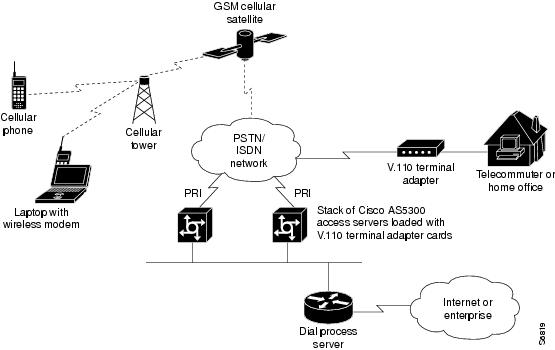
V.110 is a bit rate adaptation standard defined by the ITU that provides a standard method of encapsulating data over global system for mobile telecommunication (GSM) and ISDN networks. V.110 allows for reliable transport of asynchronous or synchronous data. V.110 adapts a low-speed connection to an ISDN B channel allowing the remote station or terminal adapter to use the fast call setup times offered by ISDN. This feature allows V.110 calls to be originated and terminated over ISDN. It also enables GSM wireless connectivity.
V.110, as an alternative to V.120, provides DTE with V-series type interfaces with access to ISDN network by bit stuffing. Many V.110 devices are used in Europe and Japan. In Japan, MICA supports the Personal-Handyphone-System Internet Access Forum Standard (PIAFS) protocol, which is similar to V.110.
The V.110 implementation for calls on MICA modems is managed by special boardware and modem code, along with the appropriate Cisco IOS image, in a manner similar to other modulation standards. This MICA V.110 implementation provides V.110 user rates ranging from 600 bps to 38,400 bps.
V.110 is supported on the following Cisco devices and network modules:
•
•
•
The digital signal processors (DSPs) on the board can function as either modems or V.110 terminal adapters (or V.120 terminal adapters for NextPort DSPs). Based on the ISDN Q.931 bearer capability information element, the Cisco IOS software configures the DSP to treat the incoming call as a modem call, a V.110 call, or a V.120 call.
Figure 1 shows a dial-in scenario for how V.110 technology can be used with a stack of Cisco AS5300-series access servers.
Figure 1 V.110 Dial-In Scenario Using a Stack of Cisco AS5300-Series Access Servers
V.120 Bit Rate Adaptation Standard
ITU-T Recommendation V.120 revised by the ITU-T Study Group 14. V.120 describes a standard that can be used for adapting terminals with non-ISDN standard network interfaces to an ISDN. It is intended to be used between two terminal adapter (TA) functional groups, between two ISDN terminal (TE1) functional groups, between a TA and a TE1, or between either a TA or TE1 and an interworking facility inside a public or private ISDN.
V.120 allows for reliable transport of synchronous, asynchronous, or bit transparent data over ISDN bearer channels. Cisco provides three V.120 support features for terminal adapters that do not send the low-layer compatibility fields or bearer capability V.120 information:
•
•
•
For terminal adapters that send the low-layer compatibility or bearer capability V.120 information, mixed V.120 and ISDN calls are supported. No special configuration is required.
V.120 is a digital rate adaptation and cannot be done on NM-AM network module analog modems. MICA DSP firmware does not have the code to terminate V.120 calls.
NextPort supports only a subset of V.120 functionalities that are supported by Cisco IOS software. Therefore, certain V.120 calls still will need to be terminated on the CPU, even if the chassis has available NextPort modems.
Managing Modems
To manage modems, perform the tasks in the following sections; the tasks you need to perform depend upon the type and needs of your system:
•
•
•
•
•
•
•
•
•
•
Managing SPE Firmware
You can upgrade your modem firmware to the latest NextPort Service Processing Element (SPE) firmware image available from Cisco. The SPE firmware image is usually retrieved from Cisco.com. You must first copy the SPE image from a TFTP server to flash memory using the copy tftp flash command. You then configure the firmware upgrade using the firmware location and firmware upgrade SPE configuration commands. The firmware location command specifies the location of the firmware file and downloads the firmware to an SPE or a range of SPEs, according to the schedule you selected for the firmware upgrade method using the firmware upgrade command.
The modem firmware upgrade commands must be saved into the system configuration using the write memory command; otherwise, at the next reboot downloading of the specified firmware will not occur.
To upgrade SPE firmware, use the following commands:
Note
Use the show modem version and show spe version commands to verify that the modems are running the portware version you specified.
The following example shows how to enter the SPE configuration mode, set the range of SPEs, specify the firmware file location in flash memory, download the file to the SPEs, and display a status report using the show spe EXEC command:
Router# configure terminalRouter(config)# spe 7/0 7/17Router(config-spe)# firmware upgrade busyoutRouter(config-spe)# firmware location flash:np_6_75Started downloading firmware flash:np_6_75.speRouter(config-spe)# exitRouter(config)# exitRouter# show spe 7...SPE SPE SPE SPE Port CallSPE# Port # State Busyout Shut Crash State Type7/00 0000-0005 ACTIVE 1 0 0 BBBBBB ______7/01 0006-0011 DOWNLOAD 1 0 0 bbbbbb ______7/02 0012-0017 DOWNLOAD 1 0 0 bbbbbb ______7/03 0018-0023 DOWNLOAD 1 0 0 bbbbbb ______...For information about upgrading Cisco 3600 Series and Cisco 3700 modems, see the Cisco 3600 Series and Cisco 3700 Series Modem Portware Upgrade Configuration Note at the following URL: http://www.cisco.com/univercd/cc/td/doc/product/access/acs_mod/cis3600/sw_conf/portware/5257d56k.htm .
Configuring Modems in Cisco Access Servers
To configure modem support for access servers such as the Cisco AS5300 and AS5800, perform the following tasks. The list describes which tasks are required and which are optional but recommended.
•
•
•
•
•
Configuring Modem Lines
You must configure the modem lines and set the country code to enable asynchronous connections into your access server. To configure the modems and line, use the following commands beginning in global configuration mode:
Step 1
Router(config)# modem country mica country
NextPort SPE modemsRouter(config)# spe country country
Microcom modemsRouter(config)# modem country microcom_hdms country
Depending on the type of modems loaded in your access server, specifies the modem vendor and country code.1 This step is only for the MICA, NextPort SPE, and Microcom modems in the Cisco AS5000 series access servers.
Table 2 through Table 5 provide a summary and comparison of the Cisco IOS commands used for the MICA and NextPort modems.
Step 2
Router(config)# line beginning-line-number ending-line-number
Enters the number of modem lines to configure. Usually this range is equal to the number of modems in the access server. Use the show line EXEC command to see which lines are available.
Step 3
Router(config-line)# transport {input | output} {all | none}
Specifies that connection protocols can be used when connecting to the line. For outgoing calls, choose the output option. For incoming calls, choose the input option. If you do not intend to dial out, choose the none option.
Step 4
Router(config-line)# autoselect {arap | ppp | slip}
Configures the line to automatically startup an AppleTalk Remote Access (ARA), PPP, and Serial Line Internet Protocol (SLIP) session. You can configure more than one protocol by entering multiple autoselect commands with the appropriate keyword.
Step 5
Router(config-line)# autoselect during-login
Configures the lines to display the username and password prompt as soon as the line is connected, rather than waiting until the user presses the Enter or Return key at the terminal.
Step 6
Router(config-line)# login authentication dialin
or
Router(config-line)# login login-name
Router(config-line)# password password
Enables authentication across all asynchronous modem logins.
Use the login authentication dialin command when authentication, authorization, and accounting (AAA) authentication has been enabled.
Use the login and password commands to configure non-AAA user authentication.
Step 7
Router(config-line)# modem dialin
Configures the modem for only incoming calls.
Step 8
Router(config-line)# exit
Returns to global configuration mode.
1 For a comprehensive list of modem country codes, see the modem country mica command and the modem country microcom_hdms command in the Cisco IOS Dial Technologies Command Reference.
Verifying the Dial-In Connection
Before configuring any additional protocols for the line such as SLIP, PPP, or ARA, test whether the dial-in connection for the access server and modem are configured correctly for dial-in access,
Note
The following is an example of a successful connection from a PC using a known good modem to dial in to a Cisco access server:
atOKatdt9,5550101CONNECT 14400/ARQ/V32/LAPM/V42BISUser Access VerificationUsername: user1Password:Router>Troubleshooting the Dial-In Connection
Depending upon the problems you experience, take the appropriate action:
•
•
–
–
–
–
Following is a sample of how to enable and then disable Cisco IOS modem debugging commands on a network access server:
Router# debug modemRouter# debug modem csmRouter# debug isdn q931Router# no debug modemRouter# no debug modem csmRouter# no debug isdn q931•
Router# debug modem ?b2b Modem Special B2Bcsm CSM activitymaintenance Modem maintenance activitymica MICA Async driver debuggingoob Modem out of band activitytdm B2B Modem/PRI TDMtrace Call Trace Upload•
For more detailed information refer to the TAC Tech Notes document, Troubleshooting Modems, at the following URL: http://www.cisco.com/en/US/partner/tech/tk801/tk36/technologies_tech_note09186a0080094eb9.shtml#
Configuring the Modem Using a Modemcap
Modems are controlled by a series of parameter settings (up to a limit of 128 characters) that are sent to the modem to configure it to interact with a Cisco device in a specified way. The parameter settings are stored in a database called a modem capability (modemcap). The Cisco IOS software contains defined modemcaps that have been found to properly initialize internal modems. Following are the names of some modemcaps available in the Cisco IOS software:
•
•
•
•
•
•
Enter these modemcap names with the modem autoconfigure type command.
For more information on creating and using modemcaps refer to the TAC Tech Notes documentation, Recommended Modemcaps for Internal Digital and Analog Modems on Cisco Access Servers, at the following URL: http://www.cisco.com/en/US/partner/tech/tk801/tk36/technologies_tech_note09186a008009491b.shtml
If your modem is not on this list and if you know what modem initialization string you need to use with it, you can create your own modemcap; see the following procedure, "Using the Modem Autoconfigure Type Modemcap Feature." To have the Cisco IOS determine what type of modem you have, use the modem autoconfigure discovery command to configure it, as described in the procedure "Using the Modem Autoconfigure Discovery Feature."
Note
Using the Modem Autoconfigure Type Modemcap Feature
If you know what modem initialization string you need to use with your modem, you can create your own modemcap by performing the following steps.
Step 1
The following example defines modemcap MODEMCAPNAME:
Router(config)# modemcap edit MODEMCAPNAME miscellaneous &FS0=1&D3Step 2
Router# terminal monitorRouter# debug confmodemModem Configuration Database debugging is onRouter#configure terminalEnter configuration commands, one per line. End with CNTL/Z.Router(config)#line 33 34Router(config-line)#modem autoconfigure type MODEMCAPNAMEJan 16 18:12:59.643: TTY34: detection speed (115200) response ---OK---Jan 16 18:12:59.643: TTY34: Modem command: --AT&FS0=1&D3--Jan 16 18:12:59.659: TTY33: detection speed (115200) response ---OK---Jan 16 18:12:59.659: TTY33: Modem command: --AT&FS0=1&D3--Jan 16 18:13:00.227: TTY34: Modem configuration succeededJan 16 18:13:00.227: TTY34: Detected modem speed 115200Jan 16 18:13:00.227: TTY34: Done with modem configurationJan 16 18:13:00.259: TTY33: Modem configuration succeededJan 16 18:13:00.259: TTY33: Detected modem speed 115200Jan 16 18:13:00.259: TTY33: Done with modem configuration
Note
Using the Modem Autoconfigure Discovery Feature
If you prefer that the modem software use its autoconfigure mechanism to configure the modem, use the modem autoconfigure discovery command.
The following example shows how to configure modem autoconfigure discovery mode:
Router# terminal monitorRouter# debug confmodemModem Configuration Database debugging is onRouter# configure terminalEnter configuration commands, one per line. End with CNTL/Z.Router(config)# line 33 34Router(config-line)# modem autoconfigure discoveryJan 16 18:16:17.724: TTY33: detection speed (115200) response ---OK---Jan 16 18:16:17.724: TTY33: Modem type is defaultJan 16 18:16:17.724: TTY33: Modem command: --AT&F&C1&D2S0=1H0--Jan 16 18:16:17.728: TTY34: detection speed (115200) response ---OK---Jan 16 18:16:17.728: TTY34: Modem type is defaultJan 16 18:16:17.728: TTY34: Modem command: --AT&F&C1&D2S0=1H0--Jan 16 18:16:18.324: TTY33: Modem configuration succeededJan 16 18:16:18.324: TTY33: Detected modem speed 115200Jan 16 18:16:18.324: TTY33: Done with modem configurationJan 16 18:16:18.324: TTY34: Modem configuration succeededJan 16 18:16:18.324: TTY34: Detected modem speed 115200Jan 16 18:16:18.324: TTY34: Done with modem configurationConfiguring the Modem Circuit Interface
The next task to complete before using the integrated modem is to configure the modem circuit interface. The basic steps are outlined next:
•
•
–
–
If you want to configure SS7, refer to Appendix G, "Configuring the Cisco SS7/C7 Dial Access Solution System," in the Cisco IOS Voice, Video, and Fax Configuration Guide.
Comparison of NextPort SPE and MICA Modem Commands
Table 2 through Table 5 compare the MICA and SPE commands.
Table 3 SPE Configuration Commands: NextPort to MICA Command Comparison
busyout
Busies out active calls.
modem busyout
firmware location filename
Specifies the firmware file to be upgraded.
Already implemented on the Cisco AS5300 and Cisco AS5800 platforms.
firmware upgrade
Specifies the upgrade method.
Already implemented on the Cisco AS5300 platform.
port modem autotest1
Enables modem autotest.
modem autotest
shutdown
Tears down all active calls on the specified SPEs.
modem shutdown
spe
Configures the SPE.
Already implemented on the Cisco AS5300 and Cisco AS5800 platforms.
spe call-record
Generates a modem call record at the end of each call.
modem call-record
spe country
Sets the system country code.
modem country
spe log-size
Sets the maximum log entries for each port.
modem buffer-size
spe poll
Sets the statistic polling interval.
modem poll
1 Cisco does not recommend the use of the modem autotest or port modem autotest command. These commands may produce unexpected results including modems being marked out of service and unscheduled reloads. These commands have been removed in Cisco IOS Release 12.3.
Configuring Cisco Integrated Modems Using Modem Attention Commands
This section provides information about using modem attention (AT) command sets to modify modem configuration. It contains the following sections:
•
•
•
Using Modem Dial Modifiers on Cisco MICA Modems
Dial modifiers permit multistage dialing for outbound modem calling through public and private switched telephone networks (PSTNs).
Note
The Cisco NAS Modem Health feature is enabled by arguments to the ATD AT command. The AT prefix informs the network access server modem that commands are being sent to it, and the D (dial string or dial) suffix dials a telephone number, establishing a connection. With NAS Modem Health feature, you can enter the dial modifiers listed in Table 6 after the D in your dial string: X, W, and the comma (,) character. These modifiers had been previously accepted without error but ignored in Cisco MICA modems on Cisco AS5300 and Cisco AS5800 universal access servers.
In the following example dial string, the portion of the string before the X is dialed for the given line type used in your configuration. All digits after the X generate the appropriate DTMF tones.
atdT5550101x,,567
Changing Configurations Manually in Integrated Microcom Modems
You can change the running configuration of an integrated modem by sending individual modem AT commands. Manageable Microcom modems have an out-of-band feature, which is used to poll modem statistics and send AT commands. The Cisco IOS software uses a direct connect session to transfer information through this out-of-band feature. To send AT commands to a Microcom modem, you must permit a direct connect session for a specified modem, open a direct connect session, send AT commands to a modem, and clear the directly connected session from the modem when you are finished.
Open a direct connect session by entering the modem at-mode slot/port command in privileged EXEC mode. From here, you can send AT commands directly from your terminal session window to the internal Microcom modems. Most incoming or outgoing calls on the modems are not interrupted when you open a direct connect session and send AT commands. However, some AT commands interrupt a call—for example, the ATH command, which hangs up a call. Open and close one direct connect session at a time. Note that multiple open sessions slow down modem performance.
Refer to the AT command set that came with your router for a complete list of AT commands that you can send to the modems.
For Microcom modems, you can clear or terminate an active directly connected session in two ways:
•
•
The following example illustrates use of the modem commands.
AT Mode Example for Integrated Modems
To establish a direct connect session to an internal or integrated modem (existing inside the router), such as the connection required for Microcom modems in the Cisco AS5200 access server, open a directly connected session with the modem at-mode command and then send an AT command to the specified modem. For example, the following example sends the AT command at%v to modem 1/1:
AS5200# modem at-mode 1/1You are now entering AT command mode on modem (slot 1 / port 1).Please type CTRL-C to exit AT command mode.at%vMNP Class 10 V.34/V.FC Modem Rev 1.0/85OKat\sIDLE 000:00:00LAST DIALNET ADDR: FFFFFFFFFFFFMODEM HW: SA 2W United States4 RTS 5 CTS 6 DSR - CD 20 DTR - RIMODULATION IDLEMODEM BPS 28800 AT%G0MODEM FLOW OFF AT\G0MODEM MODE AUT AT\N3V.23 OPR. OFF AT%F0AUTO ANS. ON ATS0=1SERIAL BPS 115200 AT%U0BPS ADJUST OFF AT\J0SPT BPS ADJ. 0 AT\W0ANSWER MESSGS ON ATQ0SERIAL FLOW BHW AT\Q3PASS XON/XOFF OFF AT\X0PARITY 8N ATThe modem responds with "OK" when the AT command you send is received.
Configuring Leased-Line Support for Analog Modems
Analog modems on the NM-8AM and NM-16AM network modules in the Cisco 2600 and 3600 series routers provide two-wire leased-line support for enterprise customers who require point-to-point connections between locations and for enterprise customers with medium to high data transfer requirements without access to other technologies or with access to only low-grade phone lines.
This feature works only with leased lines that provide loop current. Each modem used must have an RJ-11 connection to the PSTN.
Several features enhance the analog modem software:
•
•
•
•
•
•
•
To configure this support, configure one modem AT command (AT&L) and two AT registers with the modemcap entry command for the appropriate leased lines.
For leased line configuration using the AT&L{0 | 1 | 2}command:
•
•
•
–
–
The following AT registers can also be set:
•
•
For more information about using the AT command set with the modems on the NM-8AM and NM-16AM network modules in the Cisco 2600 and 3600 series routers, search Cisco.com for the publication AT Command Set and Register Summary for Analog Modem Network Modules.
To configure a modem for leased-line operation, use the following commands in global configuration mode:
The show modemcap command lists all the predefined modem types and any user-defined modemcaps that are currently configured on the router:
•
•
The important setting for leased-line support is what is defined in the modemcap as the key configuration item and its application to the leased line. Consider the following command strings:
modemcap entry micro_LL_orig:AA=S0=0&L2modemcap entry micro_LL_ans:AA=S0=1&L2AA stands for autoanswer:
•
•
If the AA feature is used, both the originating and answering modem must be put into leased-line mode with the &L2 AT command.
In the examples, the micro_LL_orig and micro_LL_ans strings are arbitrary text descriptions.
Note
To configure the modem for leased-line operation, use the modemcap entry command. For each connection, each modem must be configured as an originator or answerer.
The following example shows modemcaps for a leased-line originator and answerer and their application to specific ports:
modemcap entry micro_LL_orig:AA=S0=0&L2modemcap entry micro_LL_ans:AA=S0=1&L2line 73no execmodem InOutmodem autoconfigure type micro_LL_anstransport input allline 74no execmodem InOutmodem autoconfigure type micro_LL_origtransport input all
Note
Verifying the Analog Leased-Line Configuration
The following information is important for verifying or troubleshooting your configuration. The show modem log command displays the progress of leased-line connections. Here is an example log for a leased-line answerer. Note the "LL Answering" state and "LL Answer" in the "Direction" field of the connection report:
00:44:03.884 DTR set high00:44:02.888 Modem enabled00:43:57.732 Modem disabled00:43:52.476 Modem State:LL Answering00:43:52.476 CSM:event-MODEM_STARTING_CONNECT NewState-CSM_CONNECT_INITIATED_STATE00:43:51.112 Modem State:Waiting for Carrier00:43:43.308 Modem State:Connected00:43:42.304 Connection:TX/RX Speed = 33600/33600,Modulation = V34Direction = LL Answer, Protocol = MNP, Compression =V42bis00:43:42.304 CSM:event-MODEM_CONNECTED NewState-CONNECTED_STATE00:43:42.300 RS232:noCTS* DSR* DCD* noRI noRxBREAKTxBREAK*00:43:41.892 PPP mode active00:43:41.892 Modem enabled00:43:39.888 PPP escape maps set:TX map=00000000 RXmap=FFFFFFFF00:43:39.724 PPP escape maps set:TX map=00000000 RXmap=000A000000:43:34.444 RS232:CTS* DSR DCD noRI noRxBREAK TxBREAK00:43:11.716 Modem Analog Report:TX = -20, RX = -34,Signal to noise = 61Cisco 2600 and 3600 Series Analog Modem Leased-Line Support Examples
In the following examples, one Cisco 3620 router and one Cisco 3640 router are connected back-to-back using leased lines. The Cisco 3620 router has the originating configuration, and the Cisco 3640 router has the answering configuration.
In the dialer interface configuration, the dialer idle-timeout 0 command is added to set the dialer idle timeout to be infinity. Otherwise the leased line will go down and up every 2 minutes because the default dialer interface idle timeout is 2 minutes.
Note
Leased-Line Originating Configuration
version 12.1service timestamps debug uptimeservice timestamps log uptime!modemcap entry micro_LL_orig:AA=S0=0&L2modemcap entry micro_LL_ans:AA=S0=1&L2!interface Async33no ip addressencapsulation pppno ip route-cacheno ip mroute-cachedialer in-banddialer pool-member 1async default routingasync dynamic routingasync mode dedicatedno peer default ip addressno fair-queueno cdp enableppp direction calloutppp multilink!interface Dialer1ip address 10.1.24.1 255.255.255.0encapsulation pppno ip route-cacheno ip mroute-cachedialer remote-name sara40dialer pool 1dialer idle-timeout 0dialer max-call 4096no cdp enableppp direction calloutppp multilink!dialer-list 1 protocol ip permit!line con 0exec-timeout 0 0transport input noneline 33no execmodem InOutmodem autoconfigure type micro_LL_origtransport input allline aux 0exec-timeout 0 0line vty 0 4exec-timeout 0 0!endLeased-Line Answering Configuration
version 12.1service timestamps debug uptimeservice timestamps log uptime!modemcap entry micro_LL_orig:AA=S0=0&L2modemcap entry micro_LL_ans:AA=S0=1&L2!interface Async73no ip addressencapsulation pppno ip route-cacheno ip mroute-cachedialer in-banddialer pool-member 1async default routingasync dynamic routingasync mode dedicatedno peer default ip addressno fair-queueno cdp enableppp direction calloutppp multilink!interface Dialer1ip address 10.1.24.2 255.255.255.0encapsulation pppno ip route-cacheno ip mroute-cacheload-interval 30dialer remote-name sara20dialer pool 1dialer idle-timeout 0dialer load-threshold 1 eitherdialer max-call 4096no cdp enableppp direction calloutppp multilink!dialer-list 1 protocol ip permitline con 0exec-timeout 0 0transport input noneline 73no execmodem InOutmodem autoconfigure type micro_LL_anstransport input allline aux 0transport input allflowcontrol hardwareline vty 0 4exec-timeout 0 0!endConfiguring Modem Pooling
Modem pooling allows you to control which modem a call connects to, on the basis of dialed number identification service (DNIS). When modem pooling is not used, incoming and outgoing calls are arbitrarily assigned to modems. For example, consider a Cisco AS5300 access server loaded with a 4-port ISDN PRI card. After an analog modem call comes into the first PRI trunk, the call is greeted by a general pool of B channels and a general pool of modems. Any B channel can be connected to any modem in the access server. A random assignment takes place. Modem resources cannot be controlled.
Modem pooling assigns physical modems to a single DNIS. It enables you to create pools of physical modems in one access server, assign a unique DNIS to each modem pool, and set maximum simultaneous connect limits.
This feature is used for physically partitioning or virtually partitioning modems inside one network access server.
Modem pooling offers these benefits:
•
•
The following restrictions apply:
•
•
If you see many call failures appearing on the access server, try assigning more modems to the default pool. Use the show modem and show modem summary EXEC commands to display the modem call failure and success ratio.
•
•
Modem pooling is supported on the Cisco AS5300 access servers. To configure and manage modems, perform the tasks in the following sections; all tasks are optional and depend upon the needs of your system.
•
•
Creating a Modem Pool
You must first decide to physically partition or virtually partition your modems. For more information, see the previous section, "Configuring Modem Pooling." After you have made this decision, create a modem pool for a dial-in service or specific customer by using the following commands beginning in global configuration mode.
Step 1
Router(config)# modem-pool name
Creates a modem pool and assigns it a name, and starts modem pool configuration mode.
Step 2
Router(config-modem-pool)# pool-range number-number
Assigns a range of modems to the pool. A hyphen (-) is required between the two numbers. The range of modems you can choose from is equivalent to the number of modems in your access server that are not currently associated with another modem pool.
Step 3
Router(config-modem-pool)# called-number number [max-conn number]
Assigns the DNIS to be used for this modem pool.
The max-conn option specifies the maximum number of simultaneous connections allowed for this DNIS. If you do not specify a max-conn value, the default (total number of modems in the pool) is used.1
Step 4
Router(config-modem-pool)# Ctrl-Z
Returns to EXEC mode.
Step 5
Router# show configuration
Displays the running configuration to verify the modem pool settings. Make changes accordingly.
Step 6
Router# copy running-config startup-config
Saves the running configuration to the startup configuration.
1 The DNIS string can have an integer x to indicate a "don't care" digit for that position, for example, 555010x.
Note
Verifying Modem Pool Configuration
To verify the modem configuration, enter the show modem-pool command to display the configuration. This command displays the structure and activity status for all the modem pools in the access server. See Table 7 for a description of each display field.
Router# show modem-poolmodem-pool: System-def-Mpoolmodems in pool: 0 active conn: 00 no free modems in poolmodem-pool: v90servicemodems in pool: 48 active conn: 468 no free modems in poolcalled_party_number: 1234max conn allowed: 48, active conn: 468 max-conn exceeded, 8 no free modems in poolmodem-pool: v34servicemodems in pool: 48 active conn: 350 no free modems in poolcalled_party_number: 5678max conn allowed: 48, active conn: 350 max-conn exceeded, 0 no free modems in pool
For modem pool configuration examples, see the section "Physical Partitioning with Dial-In and Dial-Out Scenario" later in this chapter.
Check the following if you are having trouble operating your modem:
•
•
Note
Configuring Physical Partitioning
You can either physically partition or virtually partition your modems to enable different dial-in and dial-out services. This section provides information about the following optional tasks:
•
•
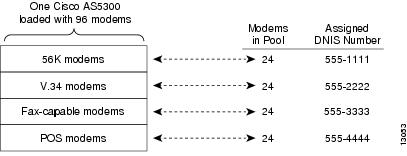
Physical partitioning uses one access server to function as multiple access servers loaded with different types of modem services (for example, V.34 modems, fax-capable modems, and point-of-sale (POS) modems). Each modem service is part of one physical modem pool and is assigned a unique DNIS number. (See Figure 2.)
Figure 2 Modem Pooling Using Physical Partitioning
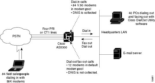
Physical partitioning can also be used to set up an access server for bidirectional dial access. (See Figure 3.)
Figure 3 shows one Cisco AS5300 access server loaded with 96 MICA modems and configured with 2 modem pools. One modem pool has 84 modems and collects DNIS. This pool is shared by 400 salespeople who remotely download e-mail from headquarters. The other modem pool contains 12 fax-capable modems and does not collect DNIS. This pool is shared by 40 employees using PCs on a LAN. Each time an outbound call is initiated by a PC, a modem on the Cisco AS5300 access server is seized and used to fax out or dial out. Not configuring DNIS support in the fax-out modem pool protects the pool from being used by the calls coming in from the field. Regardless of how many salespeople are dialing in or which telephone number they use, the fax-out and dial-out modem pool will always be reserved for the PCs connected to the LAN.
Figure 3 Modem Pooling Used for Bidirectional Dialing
Creating a Physical Partition
The following task creates one V.34 modem pool and one 56K modem pool on a Cisco AS5200. Each modem pool is configured with its own DNIS. Depending on which DNIS the remote clients dial, they connect to a 56K MICA modem or a V.34 Microcom modem.
The following hardware configuration is used on the Cisco AS5200 access server:
•
•
To configure basic physical partitioning, perform the following steps:
Step 1
Router# configure terminalRouter(config)#Step 2
Router(config)# modem-pool 56kservicesRouter(config-modem-pool)#
Note
Step 3
Router(config-modem-pool)# pool-range 1-24Step 4
Router(config-modem-pool)# called-number 5550101 max-conn 24Step 5
Router(config-modem-pool)# ^ZRouter# show modem-poolmodem-pool: System-def-Mpoolmodems in pool: 24 active conn: 00 no free modems in poolmodem-pool: 56kservicesmodems in pool: 24 active conn: 00 no free modems in poolcalled_party_number: 5550101max conn allowed: 24, active conn: 00 max-conn exceeded, 0 no free modems in poolStep 6
Router# configure terminalEnter configuration commands, one per line. End with CNTL/Z.Router(config)# modem-pool v34servicesRouter(config-modem-pool)# pool-range 25-48Router(config-modem-pool)# called-number 5550202 max-conn 24Router(config-modem-pool)# ^ZRouter# show modem-poolmodem-pool: System-def-Mpoolmodems in pool: 0 active conn: 00 no free modems in poolmodem-pool: 56kservicesmodems in pool: 48 active conn: 00 no free modems in poolcalled_party_number: 5550101max conn allowed: 48, active conn: 00 max-conn exceeded, 0 no free modems in poolmodem-pool: v34servicesmodems in pool: 48 active conn: 00 no free modems in poolcalled_party_number: 5550202max conn allowed: 48, active conn: 00 max-conn exceeded, 0 no free modems in poolRouter# copy running-config startup-config
Physical Partitioning with Dial-In and Dial-Out Scenario
The following is a bidirectional dial scenario using a Cisco AS5300 access server. Two modem pools are configured. One modem pool contains 84 56K MICA modems, which is shared by 400 remote salespeople who dial in to headquarters. The other modem pool contains 12 fax-capable modems, which are shared by 40 employees who dial out of the headquarters LAN using the Cisco DialOut Utility software. See Figure 3 for the network topology.
The following hardware configuration is used on the Cisco AS5300:
•
•
To configure physical partitioning with dial-in and dial-out capability, perform the following steps:
Step 1
Router# configure terminalRouter(config)# modem-pool 56ksalesfolksRouter(config-modem-pool)# pool-range 1-84Router(config-modem-pool)# called-number 5550303 max-conn 84Router(config-modem-pool)# exitRouter(config)# line 1 84Router(config-line)# modem dialinRouter(config-line)# transport input allRouter(config-line)# rotary 1Router(config-line)# autoselect pppRouter(config-line)# exitRouter(config)#Step 2
Router(config)# modem-pool dialoutfolksRouter(config-modem-pool)# pool-range 85-96Router(config-modem-pool)# exitRouter(config)# line 85-96Router(config-line)# refuse-message z [!NMM!] No Modems Available zRouter(config-line)# exec-timeout 0 0Router(config-line)# autoselect during-loginRouter(config-line)# autoselect pppRouter(config-line)# modem inoutRouter(config-line)# rotary 1Router(config-line)# transport preferred telnetRouter(config-line)# transport input allRouter(config-line)# exitRouter(config)#Step 3
Router(config)# interface group-async 1Router(config-if)# ip unnumbered ethernet 0Router(config-if)# encapsulation pppRouter(config-if)# async mode interactiveRouter(config-if)# ppp authentication chap pap paplocalRouter(config-if)# peer default ip address pool bidir_dial_poolRouter(config-if)# no cdp enableRouter(config-if)# no ip mroute cacheRouter(config-if)# no ip route cacheRouter(config-if)# async dynamic routingRouter(config-if)# async dynamic addressRouter(config-if)# group range 1-96Building configuration...Router(config-if)# exitStep 4
Router(config)# ip local pool bidir_dial_pool 10.4.1.1 10.4.1.96Router(config)# ^zRouter# copy running-config startup-configStep 5
Router(config)# aaa new-modelRouter(config)# aaa authentication login default tacacs+Router(config)# aaa authentication login noaaa localRouter(config)# aaa authentication login logintac tacacs+Router(config)# aaa authentication ppp ppptac tacacs+Router(config)# aaa authentication ppp paplocal localRouter(config)# aaa authorization exec tacacs+Router(config)# aaa authorization network tacacs+Router(config)# aaa authorization reverse-access tacacs+Router(config)# aaa accounting exec start-stop tacacs+Router(config)# aaa accounting network start-stop tacacs+Router(config)# aaa accounting update newinfoRouter(config)# enable password ciscoYou should also include the host name, timeout interval, and authentication key:
Router(config)# tacacs-server host 10.4.1.10Router(config)# tacacs-server timeout 20Router(config)# tacacs-server key nas1
Configuring Virtual Partitioning
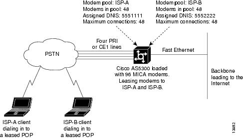
Virtual partitioning creates one large modem pool on one access server, but assigns different DNIS numbers to different customers. Each incoming DNIS consumes resources from the same modem pool, but a maximum connect option is set for each DNIS.
Figure 4 shows two Internet service provider (ISP) customers who are leasing modems from another service provider. Each ISP is assigned its own DNIS number and range of modems. Each ISP is guaranteed a certain number of physical modem ports for simultaneous connections. After an ISP uses up all the modems assigned to its DNIS, a busy signal is issued.
Figure 4 Modem Pooling Using Virtual Partitioning
Virtual partitioning essentially resells modem banks to customers, such as a small-sized ISP. However, remember that modem pooling is a single-chassis solution, not a multichassis solution. Modem pooling is not a solution for reselling ports on a large-scale basis.
The following procedure creates one modem pool on a Cisco AS5300 access server for two ISP customers. The shared modem pool is called isp56kpool. However, both ISP customers are assigned different DNIS numbers and are limited to a maximum number of simultaneous connections.
See Figure 4 for the network topology.
The following hardware configuration is used on the Cisco AS5300 access server:
•
•
To configure virtual partitioning, perform the following steps:
Step 1
Router# configure terminalEnter configuration commands, one per line. End with CNTL/Z.Router(config)#Step 2
Router(config)# modem-pool isp56kpoolRouter(config-modem-pool)#Step 3
Router(config-modem-pool)# pool-range 1-96Step 4
Router(config-modem-pool)# called-number 5550101 max-conn 48Router(config-modem-pool)# called-number 5550202 max-conn 48Step 5
Router(config-modem-pool)# ^ZRouter# show modem-poolmodem-pool: System-def-Mpoolmodems in pool: 0 active conn: 00 no free modems in poolmodem-pool: isp56kpoolmodems in pool: 96 active conn: 00 no free modems in poolcalled_party_number: 5550101max conn allowed: 48, active conn: 00 max-conn exceeded, 0 no free modems in poolcalled_party_number: 5550202max conn allowed: 48, active conn: 00 max-conn exceeded, 0 no free modems in poolRouter# copy running-config startup-config
Configuring Call Tracker
The Call Tracker feature captures detailed statistics on the status and progress of active calls and retains historical data for disconnected call sessions. Call Tracker collects session information such as call states and resources, traffic statistics, total bytes transmitted and received, user IP address, and disconnect reason. This data is maintained within the Call Tracker database tables, which are accessible through the Simple Network Management Protocol (SNMP), the CLI, or syslog.
Note
Call Tracker is notified of applicable call events by related subsystems such as ISDN, PPP, CSM, Modem, EXEC, or TCP-Clear. SNMP traps are generated at the start of each call, when an entry is created in the active table, and at the end of each call, when an entry is created in the history table. Call Record syslogs are available through configuration that will generate detailed information records for all call terminations. This information can be sent to syslog servers for permanent storage and future analysis.
Additionally, the status and diagnostic data that is routinely collected from MICA modems is expanded to include new link statistics for active calls, such as the attempted transmit and receive rates, the maximum and minimum transmit and receive rates, and locally and remotely issued retrains and speedshift counters. For more detailed information on Call Tracker logs, refer to the TAC Tech Notes document, Understanding Call Tracker Outputs, at the following URL: http://www.cisco.com/warp/public/471/calltracker_view.html
To configure Call Tracker, perform the following steps:
Verifying Call Tracker
To verify the operation of Call Tracker, use the the following command in EXEC mode:
Router# show call calltracker summary
Verifies the Call Tracker configuration and current status.
Enabling Call Tracker
The following example shows how to enable the Call Tracker feature:
calltracker enablecalltracker call-record tersecalltracker history max-size 50calltracker history retain-mins 5000!snmp-server engineID local 0012345snmp-server community public RWsnmp-server community private RWsnmp-server community wxyz123 view v1default ROsnmp-server trap-source FastEthernet0snmp-server packetsize 17940snmp-server queue-length 200snmp-server location SanJosesnmp-server contact Bobsnmp-server enable traps snmpsnmp-server enable traps calltrackersnmp-server enable traps isdn call-informationsnmp-server enable traps hsrpsnmp-server enable traps configsnmp-server enable traps entitysnmp-server enable traps envmonsnmp-server enable traps bgpsnmp-server enable traps ipmulticast-heartbeatsnmp-server enable traps rsvpsnmp-server enable traps frame-relaysnmp-server enable traps rtrsnmp-server enable traps syslogsnmp-server enable traps dlswsnmp-server enable traps dialsnmp-server enable traps dsp card-statussnmp-server enable traps voice poor-qovsnmp-server host 10.255.255.255 wxyz123snmp-server host 10.0.0.0 xxxyyy calltracker!radius-server host 172.16.0.0 auth-port 1645 acct-port 1646 non-standardradius-server key xyz!Configuring Polling of Link Statistics on MICA Modems
The status and diagnostic data that is routinely collected from MICA modems is expanded to include new link statistics for active calls, such as the attempted transmit and receive rates, the maximum and minimum transmit and receive rates, and locally and remotely issued retrains and speedshift counters. This connection data is polled from the modem at user-defined intervals and passed to Call Tracker.
To poll modem link statistics, use the following command in global configuration mode:
Router(config)# modem link-info poll time seconds
Sets the polling interval at which link statistics for active calls are retrieved from the modem.
Note
Configuring MICA In-Band Framing Mode Control Messages
Dial-in Internet connections typically start in character mode to allow the user to log in and select a preferred service. When Cisco IOS software determines that the user wants a framed interface protocol during the call, such as PPP or SLIP, commands are sent to the MICA modem so that it will provide hardware assistance with the framing. This hardware assistance reduces the Cisco IOS processing load. To avoid loss or misinterpretation of framed data during the transition, issue these commands at precise times with respect to the data being sent and received.
MICA modem framing commands can be sent in the data stream itself, which greatly simplifies Cisco IOS tasks in achieving precision timing. For PPP connections, the common way for modems to connect to the Internet, total connect time might typically be improved by 2 to 3 seconds. This functionality reduces timeouts during PPP startup and reduces startup time. If an ASCII banner is sent just before PPP startup, this feature eliminates problems with banner corruption such as truncation and extraneous characters, thus improving the performance of terminal equipment.
In earlier software, the modem interface timing rules were not well understood and were difficult or impossible to implement using the separate command interface of the modem. The practical result is that the MICA in-band framing mode reduces the number of timeouts during PPP startup, and thus reduces startup time. MICA in-band framing is supported on MICA modems in Cisco AS5300 and Cisco AS5800 access servers.
To configure the MICA in-band framing mode control messages, use the following commands beginning in global configuration mode:
The Cisco IOS software offers additional interface commands that can be set to control modem interface timing. Refer to the Cisco IOS command references for more information about the interface commands described in the following paragraphs.
When a link goes down and comes back up before the timer set by the carrier-delay command expires, the down state is effectively filtered, and the rest of the software on the switch is not aware that a link-down event occurred. Therefore, a large carrier delay timer results in fewer link-up and link-down events being detected. On the other hand, setting the carrier delay time to 0 means that every link-up and link-down event is detected.
When the link protocol goes down (because of loss of synchronization, for example), the interface hardware is reset and the data terminal ready (DTR) signal is held inactive for at least the specified interval. Setting the pulse-time command enable pulsing DTR signal intervals on serial interfaces, and is useful for handling encrypting or other similar devices that toggle the DTR signal to resynchronize.
Use the modem dtr-delay command to reduce the time that a DTR signal is held down after an asynchronous line clears and before the DTR signal is raised again to accept new calls. Incoming calls may be rejected in heavily loaded systems, even when modems are unused because the default DTR hold-down interval may be too long. The modem dtr-delay command is designed for lines used for an unframed asynchronous session such as Telnet. Lines used for a framed asynchronous session such as PPP should use the pulse-time interface command.
Enabling Modem Polling
The following example enables modem status polling through the out-of-band feature, which is associated to line 1:
Router# configure terminalRouter(config)# line 1Router(config-line)# modem status-pollSetting Modem Poll Intervals
The following example sets the time interval between polls to 10 seconds using the modem poll time global configuration command:
Router# configure terminalRouter(config)# modem poll time 10Setting Modem Poll Retry
The following example configures the server to attempt to retrieve statistics from a local modem up to five times before discontinuing the polling effort:
Router# configure terminalRouter(config)# modem poll retry 5Collecting Modem Statistics
Depending upon your modem type, the Cisco IOS software provides several show EXEC commands that allow you to display or poll various modem statistics. See Table 2 and Table 3 to find the show EXEC command appropriate for your modem type and the task you want to perform.
Logging EIA/TIA Events
To facilitate meaningful analysis of the modem log, turn the storage of specific types of EIA/TIA events on or off. To activate or inactivate the storage of a specific type of EIA/TIA modem event for a specific line or set of lines, use either of the following commands in line configuration mode, as needed:
Configuring a Microcom Modem to Poll for Statistics
Manageable Microcom modems have an out-of-band feature, which is used for polling modem statistics. To configure the system to poll for modem statistics, use the following commands in global configuration mode:
Step 1
Router(config)# modem poll time seconds
Specifies the number of seconds between statistical modem polling for Microcom modems. The default is 12 seconds. The configuration range is from 2 to 120 seconds.
Step 2
Router(config)# modem poll retry number
Sets the maximum number of polling attempts to Microcom modems. The default is three polling attempts. The configuration range is from 0 to 10 attempts.1
Step 3
Router(config)# modem status-poll
Polls for status and statistics for a Microcom modem through the modem's out-of-band feature.
Step 4
Router(config)# modem buffer-size number
Defines the number of modem events that each modem is able to store. The default is 100 events for each modem. Use the show modem log command to display modem events.
1 If the number of attempts to retrieve modem status or statistics exceeds the number you define, the out-of-band feature is removed from operation. In this case, you must reset the modem hardware using the clear modem command.
Troubleshooting Using a Back-to-Back Modem Test Procedure
You can manually isolate an internal back-to-back connection and data transfer between two modems for focused troubleshooting purposes. For example, if mobile users cannot dial in to modem 2/5 (which is the sixth modem port on the modem board in the second chassis slot), attempt a back-to-back test with modem 2/5 and a modem known to be functioning, such as modem 2/6. You might need to enable this command on several different combinations of modems to determine which one is not functioning properly. A pair of operable modems connect and complete sending data in both directions. An operable modem and an inoperable modem do not connect with each other.
To perform the modem test procedure, enter the test modem back-to-back first-slot/port second-slot/port command, as follows:
Step 1
Router# test modem back-to-back 1/1 1/0Repetitions (of 10-byte packets) [1]: 10Router#%MODEM-5-B2BCONNECT: Modems (1/1) and (1/0) connected in back-to-back test: CONNECT9600/REL-MNP%MODEM-5-B2BMODEMS: Modems (1/0) and (1/1) completed back-to-back test: success/packets = 20/20After you enter the test modem back-to-back command, you must define the number of packets sent between modems at the Repetitions prompt. The ideal range of packets to send and receive is from 1 to 100. The default is 1 packet that is 10 bytes large. The response message (for example, "success/packets = 20/20") tells you how many packets were sent in both directions compared to the total number of packets attempted to be sent in both directions. Because the software reports the packet total in both directions, the reported numbers are two times the number you originally specify.
When a known good modem is tested against a known bad modem, the back-to-back modem test fails. In the following example, modem 1/3 is suspected or proven to be inoperable or bad:
Router# test modem back-to-back 1/1 1/3Repetitions (of 10-byte packets) [1]: 10Router#%MODEM-5-BADMODEMS: Modems (1/3) and (1/1) failed back-to-back test: NOCARRIERStep 2
Router# show modem 1/3Mdm Typ Status Tx/Rx G Duration TX RX RTS CTS DSR DCD DTR1/3 V34 Idle 28800/28800 0 00:00:00 x x x x xModem 1/3, Microcom MNP10 V34 Modem (Managed), TTY4Firmware (Boot) Rev: 1.0(23) (1.0(5))Modem config: Incoming and OutgoingProtocol: reliable/MNP, Compression: V42bisManagement port config: Status polling and AT sessionManagement port status: Status polling and AT sessionTX signals: -15 dBm, RX signals: -17 dBmLast clearing of "show modem" counters never0 incoming completes, 0 incoming failures0 outgoing completes, 0 outgoing failures0 failed dial attempts, 0 ring no answers, 1 busied outs0 no dial tones, 0 dial timeouts, 0 watchdog timeouts0 no carriers, 0 link failures, 0 resets, 0 recover oob0 protocol timeouts, 0 protocol errors, 0 lost eventsTransmit Speed Counters:Connection Speeds 75 300 600 1200 2400 4800# of connections 0 0 0 0 0 0Connection Speeds 7200 9600 12000 14400 16800 19200# of connections 0 0 0 0 0 0Connection Speeds 21600 24000 26400 28800 31200 32000# of connections 0 0 0 1 0 0Connection Speeds 33600 34000 36000 38000 40000 42000# of connections 0 0 0 0 0 0Connection Speeds 44000 46000 48000 50000 52000 54000# of connections 0 0 0 0 0 0Connection Speeds 56000# of connections 0Step 3
Router# configure terminalRouter(config)# line 4Router(config-line)# modem badRouter(config-line)# exitRouter(config)# exitStep 4
Bad modems are marked with the letter B in the Mdm column of the show modem command display output.
Router# show modem%SYS-5-CONFIG_I: Configured from console by consolemInc calls Out calls Busied Failed No SuccMdm Usage Succ Fail Succ Fail Out Dial Answer Pct.1/0 0% 0 0 0 0 1 0 0 0%1/1 0% 0 0 0 0 3 0 0 0%1/2 0% 0 0 0 0 1 0 0 0%B 1/3 0% 0 0 0 0 1 0 0 0%1/4 0% 0 0 0 0 1 0 0 0%1/5 0% 0 0 0 0 1 0 0 0%1/6 0% 0 0 0 0 1 0 0 0%1/7 0% 0 0 0 0 1 0 0 0%1/8 0% 0 0 0 0 1 0 0 0%1/9 0% 0 0 0 0 1 0 0 0%1/10 0% 0 0 0 0 1 0 0 0%1/11 0% 0 0 0 0 1 0 0 0%1/12 0% 0 0 0 0 1 0 0 0%1/13 0% 0 0 0 0 1 0 0 0%1/14 0% 0 0 0 0 1 0 0 0%1/15 0% 0 0 0 0 1 0 0 0%1/16 0% 0 0 0 0 1 0 0 0%1/17 0% 0 0 0 0 1 0 0 0%1/18 0% 0 0 0 0 0 0 0 0%1/19 0% 0 0 0 0 0 0 0 0%1/20 0% 0 0 0 0 0 0 0 0%1/21 0% 0 0 0 0 0 0 0 0%1/22 0% 0 0 0 0 0 0 0 0%1/23 0% 0 0 0 0 0 0 0 0%Malfunctioning modems are also marked as Bad in the Status column of the show modem slot/port command display output, as the following example shows:
Router# show modem 1/3Mdm Typ Status Tx/Rx G Duration TX RX RTS CTS DSR DCD DTR1/3 V34 Bad 28800/28800 0 00:00:00 x x x x xModem 1/3, Microcom MNP10 V34 Modem (Managed), TTY4Firmware (Boot) Rev: 1.0(23) (1.0(5))Modem config: Incoming and OutgoingProtocol: reliable/MNP, Compression: V42bisManagement port config: Status polling and AT sessionManagement port status: Status polling and AT sessionTX signals: -15 dBm, RX signals: -17 dBmLast clearing of "show modem" counters never0 incoming completes, 0 incoming failures0 outgoing completes, 0 outgoing failures0 failed dial attempts, 0 ring no answers, 1 busied outs0 no dial tones, 0 dial timeouts, 0 watchdog timeouts0 no carriers, 0 link failures, 0 resets, 0 recover oob0 protocol timeouts, 0 protocol errors, 0 lost eventsTransmit Speed Counters:Connection Speeds 75 300 600 1200 2400 4800# of connections 0 0 0 0 0 0Connection Speeds 7200 9600 12000 14400 16800 19200# of connections 0 0 0 0 0 0Connection Speeds 21600 24000 26400 28800 31200 32000# of connections 0 0 0 1 0 0Connection Speeds 33600 34000 36000 38000 40000 42000# of connections 0 0 0 0 0 0Connection Speeds 44000 46000 48000 50000 52000 54000# of connections 0 0 0 0 0 0Connection Speeds 56000# of connections 0
Clearing a Direct Connect Session on a Microcom Modem
The examples in this section are for Microcom modems.
The following example shows how to execute the modem at-mode command from a Telnet session:
Router# modem at-mode 1/1The following example shows how to execute the clear modem at-mode command from a second Telnet session while the first Telnet session is connected to the modem:
Router# clear modem at-mode 1/1clear "modem at-mode" for modem 1/1 [confirm] <press Return>Router#The following output is displayed in the first Telnet session after the modem is cleared by the second Telnet session:
Direct connect session cleared by vty0 (172.19.1.164)Displaying Local Disconnect Reasons
To find out why a modem ended its connection or why a modem is not operating at peak performance, use the show modem call-stats [slot] EXEC command.
Disconnect reasons are described using four hexadecimal digits. The three lower-order digits can be used to identify the disconnect reason. The high-order digit generally indicates the type of disconnect reason or the time at which the disconnect occurred. For detailed information on the meaning of hexadecimal values for MICA modem disconnects, refer to the TAC Tech Notes document, MICA Modem States and Disconnect Reasons, at the following URL: http://www.cisco.com/warp/public/76/mica-states-drs.html
For detailed information on the meaning of hexadecimal values for NextPort modem disconnects, refer to the TAC Tech Notes document, Interpreting NextPort Disconnect Reason Codes, at the following URL: http://www.cisco.com/warp/public/471/np_disc_code.html .
Local disconnect reasons are listed across the top of the screen display (for example, wdogTimr, compress, retrain, inacTout, linkFail, moduFail, mnpProto, and lapmProt). In the body of the screen display, the number of times each modem disconnected is displayed (see the # column). For a particular disconnect reason, the % column indicates the percent that a modem was logged for the specified disconnect reason with respect to the entire modem pool for that given reason. For example, out of all the times the rmtLink error occurred on all the modems in the system, the rmtLink error occurred 10 percent of the time on modem 0/22.
Malfunctioning modems are detected by an unusually high number of disconnect counters for a particular disconnect reason. For example, if modem 1/0 had a high number of compression errors compared to the remaining modems in system, modem 1/0 would likely be the inoperable modem.
To reset the counters displayed by the show modem call-stats command, enter the clear modem counters command.
Note
The following example displays output for the show modem call-stats command. Because of the screen size limitation of most terminal screen displays, not all possible disconnect reasons are displayed at one time. Only the top eight most frequently experienced disconnect reasons are displayed at one time.
Router# show modem call-statsdial-in/dial-out call statisticslostCarr dtrDrop rmtLink wdogTimr compress retrain inacTout linkFailMdm # % # % # % # % # % # % # % # %* 0/0 6 2 2 3 1 0 0 0 0 0 0 0 0 0 0 0* 0/1 5 2 2 3 2 1 0 0 0 0 0 0 0 0 0 00/2 5 2 2 3 4 3 0 0 0 0 0 0 0 0 0 0* 0/3 5 2 2 3 2 1 0 0 0 0 0 0 0 0 0 0* 0/4 5 2 1 1 1 0 0 0 0 0 0 0 0 0 0 0* 0/5 5 2 2 3 2 1 0 0 0 0 0 0 0 0 0 0* 0/6 4 1 2 3 2 1 0 0 0 0 0 0 0 0 0 0* 0/7 4 1 2 3 4 3 0 0 0 0 0 0 0 0 0 0* 0/8 6 2 1 1 3 2 0 0 0 0 0 0 0 0 0 0* 0/9 5 2 1 1 1 0 0 0 0 0 0 0 0 0 0 0* 0/10 5 2 1 1 2 1 0 0 0 0 0 0 0 0 0 0* 0/11 5 2 1 1 2 1 0 0 0 0 0 0 0 0 0 00/12 5 2 2 3 2 1 0 0 0 0 0 0 0 0 0 0* 0/13 5 2 1 1 1 0 0 0 0 0 0 0 0 0 0 0* 0/14 5 2 1 1 1 0 0 0 0 0 0 0 0 0 0 0* 0/15 5 2 1 1 1 0 0 0 0 0 0 0 0 0 0 0* 0/16 5 2 1 1 1 0 0 0 0 0 0 0 0 0 0 0* 0/17 5 2 1 1 2 1 0 0 0 0 0 0 0 0 0 0* 0/18 5 2 1 1 2 1 0 0 0 0 0 0 0 0 0 0* 0/19 5 2 1 1 3 2 0 0 0 0 0 0 0 0 0 0* 0/20 5 2 1 1 1 0 0 0 0 0 0 0 0 0 0 0* 0/21 5 2 1 1 1 0 0 0 0 0 0 0 0 0 0 0* 0/22 5 2 1 1 11 10 0 0 0 0 0 0 0 0 0 0* 0/23 5 2 1 1 2 1 0 0 0 0 0 0 0 0 0 0* 2/0 4 1 2 3 2 1 0 0 0 0 0 0 0 0 0 0* 2/1 5 2 1 1 2 1 0 0 0 0 0 0 0 0 0 0* 2/2 5 2 2 3 0 0 0 0 0 0 0 0 0 0 0 0* 2/3 5 2 1 1 2 1 0 0 0 0 0 0 0 0 0 0* 2/4 5 2 1 1 2 1 0 0 0 0 0 0 0 0 0 0* 2/5 5 2 1 1 2 1 0 0 0 0 0 0 0 0 0 0* 2/6 4 1 1 1 1 0 0 0 0 0 0 0 0 0 0 0* 2/7 5 2 1 1 1 0 0 0 0 0 0 0 0 0 0 0* 2/8 5 2 1 1 1 0 0 0 0 0 0 0 0 0 0 0* 2/9 4 1 1 1 2 1 0 0 0 0 0 0 0 0 0 0* 2/10 5 2 1 1 0 0 0 0 0 0 0 0 0 0 0 0* 2/11 5 2 1 1 5 4 0 0 0 0 0 0 0 0 0 0* 2/12 5 2 1 1 2 1 0 0 0 0 0 0 0 0 0 0* 2/13 5 2 1 1 1 0 0 0 0 0 0 0 0 0 0 0* 2/14 5 2 1 1 2 1 0 0 0 0 0 0 0 0 0 0* 2/15 4 1 1 1 3 2 0 0 0 0 0 0 0 0 0 0* 2/16 4 1 1 1 3 2 0 0 0 0 0 0 0 0 0 0* 2/17 5 2 2 3 9 8 0 0 0 0 0 0 0 0 0 0* 2/18 4 1 1 1 1 0 0 0 0 0 0 0 0 0 0 0* 2/19 3 1 1 1 2 1 0 0 0 0 0 0 0 0 0 0* 2/20 7 3 1 1 8 7 0 0 0 0 0 0 0 0 0 0* 2/21 5 2 1 1 1 0 0 0 0 0 0 0 0 0 0 0* 2/22 4 1 1 1 2 1 0 0 0 0 0 0 0 0 0 0* 2/23 5 2 1 1 2 1 0 0 0 0 0 0 0 0 0 0Total 233 59 110 0 0 0 0 0dial-out call statisticsnoCarr noDitone busy abort dialStrg autoLgon dialTout rmtHgupMdm # % # % # % # % # % # % # % # %* 0/0 1 1 0 0 0 0 0 0 0 0 0 0 0 0 0 0* 0/1 0 0 0 0 0 0 0 0 0 0 0 0 0 0 0 00/2 0 0 0 0 0 0 0 0 0 0 0 0 0 0 0 0* 0/3 1 1 0 0 0 0 0 0 0 0 0 0 0 0 0 0* 0/4 1 1 0 0 0 0 0 0 0 0 0 0 0 0 0 0* 0/5 0 0 0 0 0 0 0 0 0 0 0 0 0 0 0 0* 0/6 1 1 0 0 0 0 0 0 0 0 0 0 0 0 0 0* 0/7 5 5 0 0 0 0 0 0 0 0 0 0 0 0 0 0* 0/8 0 0 0 0 0 0 0 0 0 0 0 0 0 0 0 0* 0/9 1 1 0 0 0 0 0 0 0 0 0 0 0 0 0 0* 0/10 0 0 0 0 0 0 0 0 0 0 0 0 0 0 0 0* 0/11 5 5 0 0 0 0 0 0 0 0 0 0 0 0 0 00/12 0 0 0 0 0 0 0 0 0 0 0 0 0 0 0 0* 0/13 0 0 0 0 0 0 0 0 0 0 0 0 0 0 0 0* 0/14 1 1 0 0 0 0 0 0 0 0 0 0 0 0 0 0* 0/15 1 1 0 0 0 0 0 0 0 0 0 0 0 0 0 0* 0/16 2 2 0 0 0 0 0 0 0 0 0 0 0 0 0 0* 0/17 4 4 0 0 0 0 0 0 0 0 0 0 0 0 0 0* 0/18 5 5 0 0 0 0 0 0 0 0 0 0 0 0 0 0* 0/19 1 1 0 0 0 0 0 0 0 0 0 0 0 0 0 0* 0/20 0 0 0 0 0 0 0 0 0 0 0 0 0 0 0 0* 0/21 0 0 0 0 0 0 0 0 0 0 0 0 0 0 0 0* 0/22 5 5 0 0 0 0 0 0 0 0 0 0 0 0 0 0* 0/23 1 1 0 0 0 0 0 0 0 0 0 0 0 0 0 0* 2/0 2 2 0 0 0 0 0 0 0 0 0 0 0 0 0 0* 2/1 3 3 0 0 0 0 0 0 0 0 0 0 0 0 0 0* 2/2 0 0 0 0 0 0 0 0 0 0 0 0 0 0 0 0* 2/3 0 0 0 0 0 0 0 0 0 0 0 0 0 0 0 0* 2/4 0 0 0 0 0 0 0 0 0 0 0 0 0 0 0 0* 2/5 1 1 0 0 0 0 0 0 0 0 0 0 0 0 0 0* 2/6 1 1 0 0 0 0 0 0 0 0 0 0 0 0 0 0* 2/7 4 4 0 0 0 0 0 0 0 0 0 0 0 0 0 0* 2/8 7 8 0 0 0 0 0 0 0 0 0 0 0 0 0 0* 2/9 4 1 1 1 2 1 0 0 0 0 0 0 0 0 0 0* 2/10 1 1 0 0 0 0 0 0 0 0 0 0 0 0 0 0* 2/11 1 1 0 0 0 0 0 0 0 0 0 0 0 0 0 0* 2/12 1 1 0 0 0 0 0 0 0 0 0 0 0 0 0 0* 2/13 1 1 0 0 0 0 0 0 0 0 0 0 0 0 0 0* 2/14 4 4 0 0 0 0 0 0 0 0 0 0 0 0 0 0* 2/15 1 1 0 0 0 0 0 0 0 0 0 0 0 0 0 0* 2/16 1 1 0 0 0 0 0 0 0 0 0 0 0 0 0 0* 2/17 5 5 0 0 0 0 0 0 0 0 0 0 0 0 0 0* 2/18 5 5 0 0 0 0 0 0 0 0 0 0 0 0 0 0* 2/19 3 3 0 0 0 0 0 0 0 0 0 0 0 0 0 0* 2/20 0 0 0 0 0 0 0 0 0 0 0 0 0 0 0 0* 2/21 4 4 0 0 0 0 0 0 0 0 0 0 0 0 0 0* 2/22 2 2 0 0 0 0 0 0 0 0 0 0 0 0 0 0* 2/23 0 0 0 0 0 0 0 0 0 0 0 0 0 0 0 0Total 84 0 0 0 0 0 0 0Removing Inoperable Modems
To manually remove inoperable modems from dialup services, use the following commands in line configuration mode:
If you use the modem bad command to remove an idle modem from dial services and mark it as inoperable, the letter B is used to identify the modem as bad. The letter B appears in the Status column in the output of show modem slot/port command and in the far left column in the output of the show modem command. Use the no modem bad command to unmark a modem as B and restore it for dialup connection services. If the letter B appears next to a modem number, it means the modem was removed from service with the modem shutdown command.
Note
Use the modem hold-reset command if a router is experiencing extreme modem behavior (for example, if the modem is uncontrollably dialing in to the network). This command prevents the modem from establishing software relationships such as those created by the test modem back-to-back command. The modem is unusable while the modem hold-reset command is configured. The modem hold-reset command also resets a modem that is frozen in a suspended state. Disable the suspended modem with the modem hold-reset command, and then restart hardware initialization with the no modem hold-reset command.
The following example disables a suspended modem and resets its hardware initialization:
Router# configure terminalRouter(config)# line 4Router(config-line)# modem hold-resetRouter(config-line)# no modem hold-resetThe following example gracefully disables the modem associated with line 1 from dialing and answering calls. The modem is disabled only after all active calls on the modem are dropped.
Router# configure terminalRouter(config)# line 1Router(config)# modem busyoutThe following example abruptly shuts down the modem associated with line 2. All active calls on the modem are dropped immediately.
Router# configure terminalRouter(config)# line 2Router(config)# modem shutdownIn the following example, the modem using TTY line 3 is actively supporting a call (as indicated by the asterisk). However, we want to mark the modem bad because it has poor connection performance. First, abruptly shut down the modem and drop the call with the modem shutdown command, and then enter the modem bad command to take the modem out of service.
Router# show modemInc calls Out calls Busied Failed No SuccMdm Usage Succ Fail Succ Fail Out Dial Answer Pct.1/0 37% 98 4 0 0 0 0 0 96%1/1 38% 98 2 0 0 0 0 0 98%* 1/2 2% 3 99 0 0 0 0 0 1%...Router# configure terminalRouter(config)# line 3Router(config)# modem shutdownRouter(config)# modem badRouter(config)# exitRouter# show modemInc calls Out calls Busied Failed No SuccMdm Usage Succ Fail Succ Fail Out Dial Answer Pct.1/0 37% 98 4 0 0 0 0 0 96%1/1 38% 98 2 0 0 0 0 0 98%B 1/2 2% 3 99 0 0 0 0 0 1%For more information about modem recovery procedures, refer to TAC Tech Notes Configuring MICA Modem Recovery at http://www.cisco.com/warp/public/76/modem-recovery.html and Configuring NextPort SPE Recovery at http://www.cisco.com/warp/public/76/spe-recovery.html.
Busying Out a Modem Card
To busy out a modem card in a Cisco access server, use the following commands beginning in global configuration mode:
The modem busyout command disables the modem associated with a specified line from dialing and answering calls. The modem busyout command can busy out and eventually terminate all 72 ports on the Cisco AS5800 modem card.
Monitoring Resources on Cisco High-End Access Servers
The following tasks enable you to monitor the network access server (NAS) health conditions at the DS0 level, PRI bearer channel level, and modem level. Performing these tasks will benefit network operation with improved visibility into the line status for the NAS for comprehensive health monitoring and notification capability, and improved troubleshooting and diagnostics for large-scale dial networks.
Perform the following tasks to monitor resource availability on the Cisco high-end access servers:
•
•
•
•
The CISCO-POP-MGMT-MIB supplies the DS0 busyout traps and the DS1 loopback traps. The CISCO-MODEM-MGMT-MIB supplies additional modem health traps when the modem port becomes non-functional. The CISCO-ISDN-MIB supplies additional traps for ISDN PRI channel not available.
To obtain lists of supported MIBs by platform and Cisco IOS release, and to download MIB modules, go to the Cisco MIB website on Cisco.com at
http://www.cisco.com/public/sw-center/netmgmt/cmtk/mibs.shtml.See the sections "Verifying Enabled Traps" and "Troubleshooting the Traps" to verify and troubleshoot configuration. The section "NAS Health Monitoring Example" provides output of a configuration with the NAS health monitoring features enabled.
Enabling DS0 Busyout Traps
Before you enable DS0 busyout traps, the SNMP manager must already have been installed on your workstation, and the SNMP agent must be configured on the NAS by entering the snmp-server community and snmp-server host commands. Refer to the Cisco IOS Configuration Fundamentals Configuration Guide for more information on these commands.
To generate DS0 busyout traps, use the following command in global configuration mode:
Generates a trap when there is a request to busy out a DS0 or to indicate when busyout finishes.
Enabling ISDN PRI Requested Channel Not Available Traps
To generate ISDN PRI requested channel not available traps, use the following command in global configuration mode:
Generates a trap when the NAS rejects an incoming call on an ISDN PRI interface because the channel is not available.
Enabling Modem Health Traps
To generate modem health traps, use the following command in global configuration mode:
Enabling DS1 Loopback Traps
To generate DS1 loopback traps, use the following command in global configuration mode:
Generates a trap when the DS1 line goes into loopback mode.
Verifying Enabled Traps
To verify that the traps are enabled, use the show run command. The following output indicates that all the traps are enabled:
Router(config)# show runsnmp-server enable traps ds0-busyoutsnmp-server enable traps isdn chan-not-availsnmp-server enable traps modem-healthsnmp-server enable traps ds1-loopbackAdditionally, you can use the show controllers command with the timeslots keyword to display details about the channel state. This feature shows whether the DS0 channels of a particular controller are in idle, in-service, maintenance, or busyout state. This enhancement applies to both CAS and ISDN PRI interfaces and is supported on the Cisco AS5300 and Cisco AS5400 only.
Troubleshooting the Traps
To troubleshoot the traps, turn on the debug switch for SNMP packets by entering the following command in privileged EXEC mode:
Router# debug snmp packetsCheck the resulting output to see that the SNMP trap information packet is being sent. The output will vary based on the kind of packet sent or received:
SNMP: Packet received via UDP from 10.5.4.1 on Ethernet0SNMP: Get-next request, reqid 23584, errstat 0, erridx 0sysUpTime = NULL TYPE/VALUEsystem.1 = NULL TYPE/VALUEsystem.6 = NULL TYPE/VALUESNMP: Response, reqid 23584, errstat 0, erridx 0sysUpTime.0 = 2217027system.1.0 = Cisco Internetwork Operating System Softwaresystem.6.0 =SNMP: Packet sent via UDP to 10.5.4.1You can also use trap monitoring and logging tools like snmptrapd, with debugging flags turned on, to monitor output.
NAS Health Monitoring Example
The following is sample configuration output showing all NAS health monitoring traps turned on:
Building configuration...Current configuration:! Last configuration change at 12:27:30 pacific Thu May 25 2000version xx.xservice timestamps debug uptimeservice timestamps log uptimeno service password-encryption!hostname router!aaa new-modelaaa authentication ppp default group radiusenable password <password>!spe 1/0 1/7firmware location system:/ucode/mica_port_firmwarespe 2/0 2/7firmware location system:/ucode/mica_port_firmware!resource-pool disable!clock timezone PDT -8clock calendar-validno modem fast-answermodem country mica usamodem link-info poll time 60modem buffer-size 300ip subnet-zero!isdn switch-type primary-5essisdn voice-call-failure 0!controller T1 0framing esfclock source line primarylinecode b8zspri-group timeslots 1-24!controller T1 1framing esflinecode b8zsds0-group 0 timeslots 1-24 type e&m-fgbcas-custom 0!controller T1 2shutdownclock source line secondary 2!controller T1 3shutdownclock source line secondary 3!controller T1 4shutdownclock source line secondary 4!controller T1 5shutdownclock source line secondary 5!controller T1 6shutdownclock source line secondary 6!controller T1 7shutdownclock source line secondary 7!interface Loopback0ip address 10.5.4.1!interface Ethernet0no ip addressshutdown!interface Serial0no ip addressshutdown!interface Serial1no ip addressshutdown!interface Serial2no ip addressshutdown!interface Serial3no ip addressshutdown!interface Serial0:23no ip addressip mroute-cacheisdn switch-type primary-5essisdn incoming-voice modemno cdp enable!interface FastEthernet0ip address 10.5.4.1duplex fullspeed autono cdp enable!interface Group-Async1ip unnumbered FastEthernet0encapsulation pppip tcp header-compression passiveno ip mroute-cacheasync mode interactivepeer default ip address pool swattestno fair-queueppp authentication chapppp multilinkgroup-range 1 192!interface Dialer1ip unnumbered FastEthernet0encapsulation pppip tcp header-compression passivedialer-group 1peer default ip address pool swattestpulse-time 0no cdp enable!ip local pool swattest 10.5.4.1ip default-gateway 10.5.4.1ip classless!dialer-list 1 protocol ip permitsnmp-server engineID local 00000009020000D058890CF0snmp-server community public ROsnmp-server packetsize 2048snmp-server enable traps ds0-busyoutsnmp-server enable traps isdn chan-not-availsnmp-server enable traps modem-healthsnmp-server enable traps ds1-loopbacksnmp-server host 10.5.4.1 public!radius-server host 10.5.4.1 auth-port 1645 acct-port 1646radius-server retransmit 3radius-server key <password>!line con 0transport input noneline 1 192autoselect pppmodem InOuttransport preferred nonetransport input alltransport output noneline aux 0line vty 0 4endConfiguration Examples for Modem Management
This section provides the following examples:
•
•
For additional information and examples about the commands in this chapter, refer to the Cisco IOS Dial Technologies Command Reference.
NextPort Modem Log Example
The following is partial sample output for the Cisco AS5400 with the NextPort Distributed forwarding Card (DFC). This example shows the port history event log for slot 5, port 47:
Router# show port modem log 5/47Port 5/47 Events LogService type: DATA_FAX_MODEMService mode: DATA_FAX_MODEMSession State: IDLE00:02:23: incoming called number: 35160Service type: DATA_FAX_MODEMService mode: DATA_FAX_MODEMSession State: IDLEService type: DATA_FAX_MODEMService mode: DATA_FAX_MODEMSession State: ACTIVE00:02:23: Modem State event:State: Connect00:02:16: Modem State event:State: Link00:02:13: Modem State event:State: Train Up00:02:05: Modem State event:State: EC Negotiating00:02:05: Modem State event:State: Steady00:02:05: Modem Static event:Connect Protocol : LAP-MCompression : V.42bisConnected Standard : V.34+TX,RX Symbol Rate : 3429, 3429TX,RX Carrier Frequency : 1959, 1959TX,RX Trellis Coding : 16/16Frequency Offset : 0 HzRound Trip Delay : 0 msecsTX,RX Bit Rate : 33600, 33600Robbed Bit Signalling (RBS) pattern : 0Digital Pad : NoneDigital Pad Compensation : None4 bytes of link info not formatted : 0x00 0x00 0x00 0x00 0x0000:02:06:Modem Dynamic event:Sq Value : 5Signal Noise Ratio : 40 dBReceive Level : -12 dBmPhase Jitter Frequency : 0 HzPhase Jitter Level : 2 degreesFar End Echo Level : -90 dBmPhase Roll : 0 degreesTotal Retrains : 0EC Retransmission Count : 0Characters transmitted, received : 0, 0Characters received BAD : 0PPP/SLIP packets transmitted, received : 0, 0PPP/SLIP packets received (BAD/ABORTED) : 0EC packets transmitted, received OK : 0, 0EC packets (Received BAD/ABORTED) : 0Modem Performance Summary Example
You can display a high level summary of the performance of a modem with the show modem summary command:
Router# show modem summaryIncoming calls Outgoing calls Busied Failed No SuccUsage Succ Fail Avail Succ Fail Avail Out Dial Ans Pct.14% 2489 123 15 0 0 15 0 3 3 95%Modem AT-Mode Example
The following example shows that modem 1/1 has one open AT directly connected session:
Router# show modem at-modeActive AT-MODE management sessions:Modem User's Terminal1/1 0 cty 0Connection Speed Performance Verification Example
Making sure that your modems are connecting at the correct connection speeds is an important aspect of managing modems. The show modem connect-speeds and show modem commands provide performance information that allow you to investigate possible inoperable or corrupt modems or T1/E1 lines. For example, suppose you have an access server that is fully populated with V.34 modems. If you notice that modem 1/0 is getting V.34 connections only 50 percent of the time, whereas all the other modems are getting V.34 connections 80 percent of the time, then modem 1/0 is probably malfunctioning. If you are reading low connection speeds across all the modems, you may have a faulty channelized T1 or ISDN PRI line connection.
To display connection speed information for all modems that are running in your system, use the show modem connect-speeds max-speed EXEC command. Because most terminal screens are not wide enough to display the entire range of connection speeds at one time (for example, 75 to 56,000 bps), the max-speed argument is used. This argument specifies the contents of a shifting baud-rate window, which provides you with a snapshot of the modem connection speeds for your system. Replace the max-speed argument with the maximum connect speed that you want to display. You can specify from 12,000 to 56,000 bps. If you are interested in viewing a snapshot of lower baud rates, specify a lower connection speed. If you are interested in displaying a snapshot of higher rates, specify a higher connection speed.
The following example displays connection speed information for modems running up to 33,600 bps:
Router# show modem connect-speeds 33600transmit connect speedsMdm 14400 16800 19200 21600 24000 26400 28800 31200 33600 TotCnt* 0/0 0 0 0 0 0 0 4 4 1 9* 0/1 2 0 0 0 0 0 3 3 1 90/2 2 0 0 0 0 1 2 4 1 10* 0/3 0 0 0 1 0 0 3 4 1 9* 0/4 1 0 0 0 0 2 2 1 1 7* 0/5 0 0 0 0 0 0 4 4 1 9* 0/6 0 0 0 0 0 1 3 3 1 8* 0/7 0 0 0 2 0 0 4 3 1 10* 0/8 2 0 0 0 0 0 3 4 1 10* 0/9 0 0 0 0 0 0 4 3 0 7* 0/10 1 0 0 0 0 1 3 2 1 8* 0/11 0 0 0 0 0 0 4 3 1 80/12 1 0 0 0 0 0 4 2 1 8* 0/13 0 0 0 0 0 0 4 2 1 7* 0/14 1 0 0 0 0 1 2 2 1 7* 0/15 0 0 0 0 0 0 4 2 1 7* 0/16 0 0 0 1 0 0 3 2 1 7* 0/17 1 0 0 0 0 0 4 2 1 8* 0/18 1 0 0 0 0 0 3 3 1 8* 0/19 0 0 0 0 0 0 5 3 1 9* 0/20 0 0 0 0 0 0 4 2 1 7* 0/21 1 0 0 0 0 0 4 2 0 7* 0/22 0 0 0 0 0 0 7 9 1 17* 0/23 0 0 0 0 0 2 2 3 1 8* 2/0 0 0 0 1 0 0 3 3 1 8* 2/1 0 0 0 0 0 0 5 2 1 8* 2/2 0 0 0 1 0 0 4 1 1 7* 2/3 1 0 0 0 0 0 4 2 1 8* 2/4 0 0 0 0 0 0 5 2 1 8* 2/5 0 0 0 0 0 0 4 3 1 8* 2/6 0 0 0 0 0 0 3 2 1 6* 2/7 1 0 0 0 0 1 3 2 0 7* 2/8 1 0 0 0 0 0 3 2 1 7* 2/9 0 0 0 0 0 1 3 2 1 7* 2/10 2 0 0 0 0 2 1 0 1 6* 2/11 0 0 0 1 0 1 3 5 1 11* 2/12 0 0 0 0 0 0 5 2 1 8* 2/13 1 0 0 0 0 0 5 0 1 7* 2/14 1 0 0 0 0 0 3 3 1 8* 2/15 1 0 0 0 0 1 2 3 1 8* 2/16 0 0 0 0 0 0 4 3 1 8* 2/17 0 0 0 0 0 0 5 11 0 16* 2/18 0 0 0 1 0 1 1 2 1 6* 2/19 0 0 0 0 0 0 2 3 1 6* 2/20 1 0 0 0 0 2 3 9 1 16* 2/21 1 0 0 0 0 0 4 1 1 7* 2/22 0 0 0 1 0 0 2 3 1 7* 2/23 0 0 0 0 0 1 3 3 1 8Tot 23 0 0 9 0 18 165 141 44 400Tot % 5 0 0 2 0 4 41 35 11receive connect speedsMdm 14400 16800 19200 21600 24000 26400 28800 31200 33600 TotCnt* 0/0 0 0 0 0 0 4 1 3 1 9* 0/1 2 0 0 0 0 3 1 2 1 90/2 2 0 0 0 0 3 1 3 1 10* 0/3 0 0 0 1 0 3 4 0 1 9* 0/4 1 0 0 0 0 4 0 1 1 7* 0/5 0 0 0 0 0 4 3 1 1 9* 0/6 0 0 0 0 0 4 0 3 1 8* 0/7 0 0 0 2 0 4 1 2 1 10* 0/8 2 0 0 0 0 3 0 5 0 10* 0/9 0 0 0 0 0 4 2 0 1 7* 0/10 1 0 0 0 0 4 0 2 1 8* 0/11 0 0 0 0 0 4 0 3 1 80/12 1 0 0 0 0 2 2 2 1 8* 0/13 0 0 0 0 0 4 1 1 1 7* 0/14 1 0 0 0 0 2 3 0 1 7* 0/15 0 0 0 0 0 4 1 1 1 7* 0/16 0 0 0 1 0 3 2 0 1 7* 0/17 1 0 0 0 0 4 1 1 1 8* 0/18 1 0 0 0 0 3 2 1 1 8* 0/19 0 0 0 0 0 5 1 2 1 9* 0/20 0 0 0 0 0 4 0 3 0 7* 0/21 1 0 0 0 0 4 0 1 1 7* 0/22 0 0 0 0 0 6 6 4 1 17* 0/23 0 0 0 0 0 4 2 1 1 8* 2/0 0 0 0 1 0 3 1 2 1 8* 2/1 0 0 0 0 0 3 3 1 1 8* 2/2 0 0 0 1 0 4 0 1 1 7* 2/3 1 0 0 0 0 3 2 1 1 8* 2/4 0 0 0 0 0 4 2 1 1 8* 2/5 0 0 0 0 0 4 1 2 1 8* 2/6 0 0 0 0 0 3 0 3 0 6* 2/7 1 0 0 0 1 2 2 0 1 7* 2/8 1 0 0 0 0 3 0 2 1 7* 2/9 0 0 0 0 0 4 1 1 1 7* 2/10 2 0 0 0 0 3 0 0 1 6* 2/11 0 0 0 1 0 3 1 5 1 11* 2/12 0 0 0 0 0 4 3 0 1 8* 2/13 1 0 0 0 0 2 3 0 1 7* 2/14 1 0 0 0 0 3 2 1 1 8* 2/15 1 0 0 0 0 3 0 3 1 8* 2/16 0 0 0 0 0 4 0 4 0 8* 2/17 0 0 0 0 0 5 2 8 1 16* 2/18 0 0 1 0 0 2 1 1 1 6* 2/19 0 0 0 0 0 2 2 1 1 6* 2/20 1 0 0 0 0 4 2 8 1 16* 2/21 1 0 0 0 0 4 0 1 1 7* 2/22 0 0 1 0 0 2 0 3 1 7* 2/23 0 0 0 0 0 4 2 1 1 8Tot 23 0 2 7 1 167 64 92 44 400Tot % 5 0 0 1 0 41 16 23 11Cisco and the Cisco Logo are trademarks of Cisco Systems, Inc. and/or its affiliates in the U.S. and other countries. A listing of Cisco's trademarks can be found at www.cisco.com/go/trademarks. Third party trademarks mentioned are the property of their respective owners. The use of the word partner does not imply a partnership relationship between Cisco and any other company. (1005R)
Any Internet Protocol (IP) addresses and phone numbers used in this document are not intended to be actual addresses and phone numbers. Any
examples, command display output, network topology diagrams, and other figures included in the document are shown for illustrative purposes
only. Any use of actual IP addresses or phone numbers in illustrative content is unintentional and coincidental.

© 2001-2009 Cisco Systems, Inc. All rights reserved.