Multi-Topology Routing
Available Languages
Table Of Contents
Prerequisites for Multi-Topology Routing
Restrictions for Multi-Topology Routing
Information About Multi-Topology Routing
Unicast Topology Configuration for MTR
Multicast Topology Configuration for MTR
Routing Protocol Support for MTR
BGP Routing Protocol Support for MTR
BGP Sessions for Class-Specific Topologies
Topology Translation Using BGP
Network Management Support for MTR
Guidelines for Enabling and Disabling MTR
How to Configure Multi-Topology Routing
Configuring a Unicast Topology for MTR
Configuring a Multicast Topology for MTR
Configuring MTR Traffic Classification
MTR and QoS Traffic Classification in the Same Network
Activating an MTR Topology Using OSPF
Activating an MTR Topology Using EIGRP
Activating an MTR Topology Using IS-IS
Activating an MTR Topology Using BGP
Importing Routes from an MTR Topology Using BGP
Configuring an MTR Topology in Interface Configuration Mode
Activating an MTR Topology in Interface Configuration Mode Using OSPF
OSPF Interface Topology Configuration
Activating an MTR Topology in Interface Configuration Mode Using EIGRP
EIGRP Interface Topology Configuration
Activating an MTR Topology in Interface Configuration Mode Using IS-IS
IS-IS Interface Topology Configuration
Configuring SNMP Support for MTR
Associating an SNMP Context with a VRF for MTR
Associating an SNMP Context with a Data Topology for MTR
Associating an SNMP Context with a Routing Protocol for MTR
Enabling and Monitoring MTR Topology Statistics Accounting
Enabling Topology Statistics Accounting for MTR
Monitoring Interface and Topology IP Traffic Statistics for MTR
Testing Network Connectivity for MTR
Configuration Examples for Multi-Topology Routing
Unicast Topology for MTR: Examples
Global Interface Configuration Example
Incremental Forwarding Configuration Example
Unicast Topology Verification Example
Multicast Topology for MTR: Examples
Route Replication Configuration Example
Using a Unicast RIB for Multicast RPF Configuration Example
Multicast Verification Example
MTR Traffic Classification: Examples
Activating an MTR Topology Using OSPF: Examples
Activating an MTR Topology Using EIGRP: Examples
Activating an MTR Topology Using IS-IS: Examples
Activating an MTR Topology Using BGP: Examples
BGP Topology Translation Configuration
BGP Scope Global and VRF Configuration
Importing Routes from an MTR Topology Using BGP: Example
MTR Topology in Interface Configuration Mode: Examples
MTR OSPF Topology in Interface Configuration Mode: Examples
MTR EIGRP Topology in Interface Configuration Mode: Examples
MTR IS-IS Topology in Interface Configuration Mode: Examples
SNMP Support for MTR: Examples
Monitoring Interface and Topology IP Traffic Statistics: Examples
Testing Network Connectivity for MTR: Examples
Feature Information for Multi-Topology Routing
Multi-Topology Routing
First Published: February 27, 2007Last Updated: June 4, 2007Multi-Topology Routing (MTR) allows the configuration of service differentiation through class-based forwarding. MTR supports multiple unicast topologies and a separate multicast topology. A topology is a subset of the underlying network (or base topology) characterized by an independent set of Network Layer Reachability Information (NLRI). A topology can overlap with another or share any subset of the underlying network. MTR provides separate forwarding capabilities on a per topology basis. A separate forwarding table is maintained for each topology, allowing you to broadly apply independent forwarding configurations or add a level of granularity to independent forwarding configurations. MTR can be used, for example, to define separate topologies for voice, video, and data traffic classes.
Finding Feature Information in This Module
Your Cisco IOS software release may not support all of the features documented in this module. To reach links to specific feature documentation in this module and to see a list of the releases in which each feature is supported, use the "Feature Information for Multi-Topology Routing" section.
Finding Support Information for Platforms and Cisco IOS and Catalyst OS Software Images
Use Cisco Feature Navigator to find information about platform support and Cisco IOS and Catalyst OS software image support. To access Cisco Feature Navigator, go to http://www.cisco.com/go/cfn. An account on Cisco.com is not required.
Contents
•
Prerequisites for Multi-Topology Routing
•
•
•
•
•
Prerequisites for Multi-Topology Routing
•
•
•
Restrictions for Multi-Topology Routing
•
•
•
•
•
Information About Multi-Topology Routing
You should understand the following concepts before configuring MTR in a production network:
•
•
•
•
•
•
MTR Overview
MTR introduces the capability to configure service differentiation through class-based forwarding. There are two primary components to configuring MTR: independent topology configuration and traffic classification configuration.
A topology is defined as a subset of routers and links in a network, for which a separate set of routes is calculated. The entire network itself, for which the usual set of routes is calculated, is known as the base topology. The base topology (or underlying network) is characterized by the NLRI that a router uses to calculate the global routing table to make routing and forwarding decisions. In other words, the base topology is the default routing environment that exists prior to enabling MTR.
Any additional topologies are known as class-specific topologies and are a subset of the base topology. Each class-specific topology carries a class of traffic and is characterized by an independent set of NLRI that is used to maintain a separate Routing Information Base (RIB) and Forwarding Information Base (FIB). This design allows the router to perform independent route calculation and forwarding for each topology.
Within a given router, MTR creates a selection of routes upon which to forward to a given destination. The specific choice of route is based on the class of the packet being forwarded, a class that is an attribute of the packet itself. This design allows packets of different classes to be routed independently from one another. The path that the packet follows is determined by classifiers configured on the routers and interfaces in the network. Figure 1 shows the base topology, which is a superset of the red, blue, and green topologies.
Figure 1 MTR Base Topology
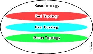
Figure 2 shows an MTR-enabled network that is configured using the service separation model. The base topology (shown in black) uses NLRI from all reachable devices in the network. The blue, red, and purple paths each represent a different class-specific topology. Each class-specific topology calculates a separate set of paths through the network. Routing and forwarding are independently calculated based on individual sets of NLRI that are carried for each topology.
Figure 2 Defining MTR Topologies
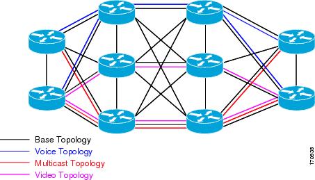
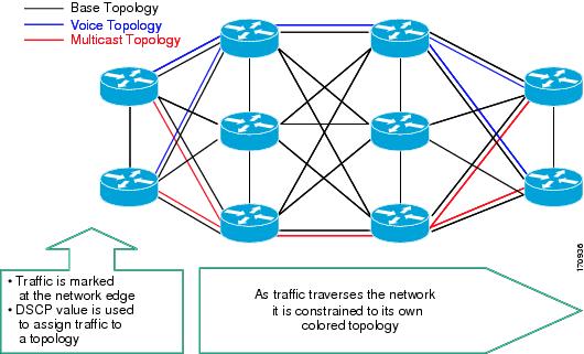
Figure 3 shows that the traffic is marked at the network edge. As the traffic traverses the network, the marking is used during classification and forwarding to constrain the traffic to its own colored topology.
Figure 3 Traffic Follows Class-Specific Forwarding Paths
The same topology can have configured backup paths. In Figure 4, the preferential path for the voice topology is represented by the solid blue line. In case this path becomes unavailable, MTR can be configured to choose the voice backup path represented by the dotted blue line. Both of these paths represent the same topology and none overlap.
Figure 4 MTR Backup Contingencies Within a Topology
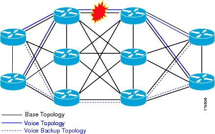
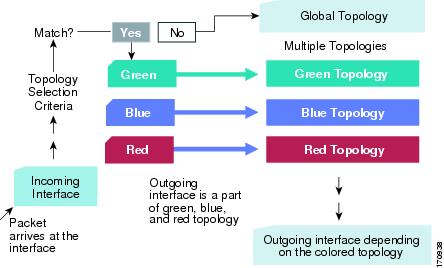
Figure 5 shows the MTR forwarding model at the system level. When a packet arrives at the incoming interface, the marking is examined. If the packet marking matches a topology, the associated topology is consulted, the next hop for that topology is determined, and the packet is forwarded. If there is no forwarding entry within a topology, the packet is dropped. If the packet does not match any classifier, it is forwarded to the base topology. The outgoing interface is a function of the colored route table in which the lookup is done.
Figure 5 MTR Forwarding at the System Level
MTR is implemented in Cisco IOS software on a per address family and subaddress family basis. Only the IPv4 (unicast and multicast) address family is currently supported. MTR supports up to 32 unicast topologies (including the base topology) and a separate multicast topology. A topology can overlap with another or share any subset of the underlying network. Each topology is configured with a unique topology ID. The topology ID is configured under the routing protocol and is used to identify and group NLRI for each topology in updates for a given protocol.
Unicast Topology Configuration for MTR
Up to 32 unicast topologies can be configured on each router. The topology is first defined by entering the global-address-family command in global configuration mode. The address family and optionally the subaddress family are specified in this step. The topology subcommand is then entered in global address family configuration mode. This command places the router in address family topology configuration mode. The following global topology configuration parameters are applied in this mode:
•
•
•

Note
Multicast Topology Configuration for MTR
Cisco IOS software supports legacy (pre-MTR) IP multicast behavior by default. MTR support for IP multicast must be explicitly enabled. Legacy IP multicast uses reverse path forwarding on routes in the unicast RIB (base unicast topology) to build multicast distribution trees (MDTs).
Note
MTR introduces a multicast topology that is completely independent from the unicast topology. MTR integration with multicast will allow the user to control the path of multicast traffic in the network.
The multicast topology maintains separate routing and forwarding tables. The following list summarizes MTR multicast support that is integrated into Cisco IOS software:
•
•
•
•
Multicast support is enabled by configuring the ip multicast-routing command in global configuration mode, as in pre-MTR software. MTR support for multicast is enabled by configuring the ip multicast rpf multitopology command. The global-address-family command is entered with the IPv4 address family and multicast subaddress family. The topology command is then entered with the base keyword. The following global topology configuration parameters are applied in this mode:
•
•
Note
Routing Protocol Support for MTR
IP routing must be enabled on the router in order for MTR to operate. MTR supports static and dynamic routing in Cisco IOS software. Dynamic routing can be enabled per-topology to support inter-domain and intra-domain routing. Route calculation and forwarding are independent for each topology. MTR support is integrated into Cisco IOS software for the following protocols:
•
•
•
•
Per-topology configuration is applied under the router address family configuration of the global routing process (router configuration mode). The address family and subaddress family are specified when entering address-family configuration mode. The topology name and topology ID are specified under the address-family configuration by entering the topology command.
Each topology is configured with a unique topology ID. The topology ID is configured under the routing protocol and is used to identify and group NLRI for each topology in updates for a given protocol. In OSPF, EIGRP, and IS-IS, the topology ID is entered during the first configuration of the topology command for a class-specific topology. In BGP, the topology ID is configured by entering the bgp tid command under the topology configuration.
Class-specific topologies can be configured with different metrics than the base topology. Interface metrics configured on the base topology can be inherited by the class-specific topology. Inheritance occurs if no explicit inheritance metric is configured in the class-specific topology.
BGP support is configured only in router configuration mode. IGP support is configured in router configuration mode and/or interface configuration mode.
By default, interfaces are not included in non-base topologies. For routing protocol support for EIGRP, IS-IS, and OSPF, explicit configuration of a non-base topology on an interface is required. The default behavior can be overridden by using the all-interfaces command in address family topology configuration mode. The all-interfaces command causes the non-base topology to be configured on all interfaces of the router that are part of the default address space or the VRF in which the topology is configured.
BGP Routing Protocol Support for MTR
Before using BGP to support MTR, you should be familiar with the following concepts:
•
•
BGP Network Scope
A new configuration hierarchy, named scope, has been introduced into the BGP protocol. To implement MTR for BGP, the scope hierarchy is required, but the scope hierarchy is not limited to MTR use. The scope hierarchy introduces some new configuration modes such as router scope configuration mode. Router scope configuration mode is entered by configuring the scope command in router configuration mode, and a collection of routing tables is created when this command is entered. BGP commands configured under the scope hierarchy are configured for a single network (globally), or on a per-VRF basis, and are referred to as scoped commands. The scope hierarchy can contain one or more address families.
MTR CLI Hierarchy Under BGP
The BGP CLI has been modified to provide backwards compatibility for pre-MTR BGP configuration and to provide a hierarchical implementation of MTR. Router configuration mode is backwards compatible with the pre-address family and pre-MTR configuration CLI. Global commands that affect all networks are configured in this configuration mode. For address-family and topology configuration, general session commands and peer templates can be configured to be used in the address-family or topology configuration modes.
After any global commands are configured, the scope is defined either globally or for a specific VRF. Address family configuration mode is entered by configuring the address-family command in router scope configuration mode or router configuration mode. Unicast is the default address family if no subaddress family (SAFI) is specified. MTR supports only the IPv4 address family with a SAFI of unicast or multicast. Entering address family configuration mode from router configuration mode configures BGP to use pre-MTR-based CLI. This configuration mode is backwards compatible with pre-existing address family configurations. Entering address family configuration mode from router scope configuration mode configures the router to use the hierarchical CLI that supports MTR. Address family configuration parameters that are not specific to a topology are entered in this address family configuration mode.
BGP topology configuration mode is entered by configuring the topology (BGP) command in address family configuration mode. Up to 32 topologies (including the base topology) can be configured on a router. The topology ID is configured by entering the bgp tid command. All address family and subaddress family configuration parameters for the topology are configured here.
Note
The following shows the hierarchy levels that are used when configuring BGP for MTR implementation:
router bgp <autonomous-system-number>
 ! Global commands
 scope {global | vrf <vrf-name>}
  ! Scoped commands
  address-family {<afi>} [<safi>]
   ! Address family specific commands
   topology {<topology-name> | base}
    ! topology specific commands
BGP Sessions for Class-Specific Topologies
MTR is configured under BGP on a per-session basis. The base unicast and multicast topologies are carried in the global (default) session. A separate session is created for each class-specific topology that is configured under a BGP routing process. Each session is identified by its topology ID. BGP performs a best-path calculation individually for each class-specific topology. A separate RIB and FIB are maintained for each session.
Topology Translation Using BGP
Depending on the design and policy requirements for your network, you may need to install routes from a class-specific topology on one router in a class-specific topology on a neighboring router. Topology translation functionality using BGP provides support for this operation. Topology translation is BGP neighbor-session based. The neighbor translate-topology command is configured using the IP address and topology ID from the neighbor.
The topology ID identifies the class-specific topology of the neighbor. The routes in the class-specific topology of the neighbor are installed in the local class-specific RIB. BGP performs a best-path calculation on all installed routes and installs these routes into the local class-specific RIB. If a duplicate route is translated, BGP will select and install only one instance of the route per standard BGP best-path calculation behavior.
Topology Import Using BGP
Topology import functionality using BGP is similar to topology translation. The difference is that routes are moved between class-specific topologies on the same router using BGP. This function is configured by entering the import topology command. The name of the class-specific topology or base topology is specified when entering this command. Best-path calculations are run on the imported routes before they are installed into the topology RIB. This command also includes a route-map keyword to allow you to filter routes that are moved between class-specific topologies.
MTR Traffic Classification
MTR cannot be enabled on a router until traffic classification has been configured, even if only one class-specific topology has been configured. Traffic classification is used to configure topology specific forwarding behaviors when multiple topologies are configured on the same router. Traffic classification must be applied consistently throughout the network. Class-specific packets are associated with the corresponding topology table forwarding entries.
Traffic classification is configured using the Modular QoS CLI (MQC). MTR traffic classification is similar to QoS traffic classification. However, there is an important distinction. MTR traffic classification is defined globally for each topology, rather than at the interface level as in Quality of Service (QoS).
A subset of DSCP bits is used to encode classification values in the IP packet header. A class map is configured to define the traffic class by entering the class-map command in global configuration mode. Only the match-any keyword is supported for MTR. The traffic class is associated with a policy by configuring the policy-map type class-routing ipv4 unicast command in global configuration mode. The policy is activated for the topology by configuring the service-policy type class-routing command in global address family configuration mode. When configured, the service policy is associated with all interfaces on the router.
Some of the same goals can be achieved through QoS configuration, to which MTR provides a more powerful and flexible alternative. MTR traffic classification and IP Differentiated Services or IP Precedence-based traffic classification can be configured in the same network. However, MTR requires exclusive use of some subset of the DSCP bits in the IP packet header for specific topology traffic. In a network where MTR and QoS traffic classification are configured, simultaneous configuration must be carefully coordinated.
Network Management Support for MTR
Standard network management utilities, such as ping and traceroute, have been enhanced to support MTR. You can configure a standard or extended ping using the topology name in place of a hostname or IP address. Traceroute has been similarly enhanced. Context-based Simple Network Management Protocol (SNMP) functionality has been integrated into Cisco IOS software and can be used to support MTR.
ISSU—MTR
All protocols and applications that support MTR and that also support In Service Software Upgrade (ISSU) have extended their ISSU support to include the MTR functionality. See the Cisco IOS In Service Software Upgrade Process module for information on ISSU-capable protocols and applications.
ISSU allows a high-availability (HA) system to run in Stateful Switchover (SSO) mode even when different versions of Cisco IOS software are running on the active and standby Route Processors (RPs). This feature allows the system to switch over to a secondary RP that is running upgraded (or downgraded) software and to continue forwarding packets without session loss and with minimal or no packet loss.
This feature is enabled by default.
MTR Deployment Models
The base topology is the superset of all topologies in the network. It is defined by NLRI for all reachable routers regardless of the deployment model that is used. MTR can be deployed using the service separation MTR model shown in Figure 6, or it can deployed using the overlapping MTR model shown in Figure 7. Each of these models represent a different approach to deploying MTR. However, these models are not mutually exclusive. Any level of variation of a combined model can be deployed.
Service Separation MTR Model
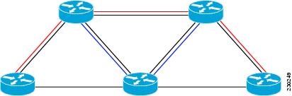
Figure 6 shows the service separation model where no colored topologies (except for the base) overlap with each other. In the service separation model, each class of traffic is constrained to its own exclusive topology. This model restricts the given class of traffic to a subset of the network. This model is less configuration intensive because no topology-specific metrics need to be configured.
Figure 6 Service-Separation MTR Model
Overlapping MTR Model
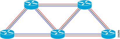
In the overlapping MTR model, all topologies are configured to run over all routers in the network. This model provides the highest level of redundancy. All classes of traffic may use all links. Per-topology metrics are then configured to bias different classes of traffic to use different parts of the network. The redundancy that this model provides, however, makes it more configuration intensive. Figure 7 shows the red and gray topologies. All topologies are configured to run over all network routers. In this model, per-topology metrics are configured to bias the preferred routes for each topology.
Figure 7 Overlapping MTR Model
MTR Deployment Configuration
MTR supports both full and incremental deployment configurations. To support these options, MTR provides two different, configurable forwarding rules. For full deployment, MTR supports a (default) longest-match lookup in only the forwarding table of the corresponding class-specific topology. If no route is found, the packet is dropped. For incremental deployment, MTR supports a longest- match lookup first in the forwarding table for the corresponding class-specific topology, and subsequently, in the base topology if no class-specific entry is found. The former forwarding rule is known as "strict mode," the latter as "incremental mode."
Full Deployment
Strict forwarding mode is the default forwarding mode in MTR. In this mode, the router will look for a forwarding route only in the class-specific FIB. If no forwarding route is found, the packet is dropped. In this mode, the router performs a longest match look up for the topology FIB entry. This mode is designed for full deployment, where MTR is enabled on every router in the network or every router in the topology. Strict forwarding mode should be enabled after an incremental deployment transition has been completed or when all routers in the network or topology are MTR enabled. Strict forwarding mode can be enabled after incremental forwarding mode by entering the no form of the forward-base command.
Incremental Deployment
Incremental forwarding mode is designed to support transitional or incremental deployment of MTR, where there are routers in the network that are not MTR enabled. In this mode, the router will look for a forwarding entry first in the class-specific FIB. If an entry is not found, the router will then look for the longest match in the base topology FIB. If an entry is found in the base topology FIB, the packet will be forwarded on the base topology. If a forwarding entry is not found in the base topology FIB, the packet is dropped.
This mode is designed to preserve connectivity during an incremental deployment of MTR and is recommended to be used only during migration (the transition from a non-MTR to MTR enabled network). Class-specific traffic for a given destination is forwarded over contiguous segments of the class-specific topology containing that destination; otherwise it is forwarded over the base topology.
This forwarding mode can also be enabled to support mixed networks where some routers are not configured to run MTR. Incremental forwarding mode is enabled by entering the forward-base command in address family topology configuration mode.
Guidelines for Enabling and Disabling MTR
The section provides guidelines and procedures for enabling or disabling MTR in a production network. These guidelines assume that all participating networking devices are running a software image that supports MTR. They are designed to prevent major traffic interruptions due to misconfiguration and to minimize temporary transitional effects that can occur when introducing or removing a topology from a network. The procedures described below must be implemented in the order that they are described.
First, create a class-specific topology on all networking devices and enable incremental forwarding mode by entering the forward-base command in the address family topology configuration. Incremental forwarding should be configured whenever a topology is introduced or removed from the network. The topology is defined as a global container at this stage. No routing or forwarding can occur within the topology. Routing protocol support should not be configured.
Second, configure classification rules for the class-specific topology. Classification must be consistently applied on all routers in the topology; each router has identical classifier configuration. The topology is activated when a valid classification configuration is attached to the global topology configuration. Reachability can be verified, for interfaces and networking devices that are in the same topology and configured with identical classification, using ping and trace route.
Third, configure routing protocol support and/or static routing. The routers in the topology should be configured one at a time. This configuration includes interface, router process, and routing protocol-specific metrics and filters.
You should enable routing in the topology using a physical pattern in a contiguous manner relative to a single starting point. For example, you should configure all interfaces on a single router, and then all interfaces on each adjacent router. You should follow this pattern until the task is complete. The starting point can be on the edge or core of the network. This recommendation is designed to increase the likelihood that class-specific traffic is forwarded on the same paths in the incremental topology during as it is on the full topology when MTR is completely deployed.
Incremental forwarding should be disabled (if your network design requires strict forwarding mode) only after routing has been configured on all routers in a given topology. At this stage, MTR is fully operational. Class-specific traffic is forwarded only over devices within the topology. Traffic that is not classified or destined for the topology is dropped.
When disabling a topology, you should reenable incremental forwarding mode. You should remove custom route configuration, such as route summarization and default routes before disabling a topology, and you should reapply custom route configuration only after the topology is reenabled. This recommendation is designed to prevent traffic interruption, as some destinations may be obscured during the transition. Custom route configuration is most useful when all of the more specific routes are available in the routing table of the topology.
Note
How to Configure Multi-Topology Routing
This section contains the following tasks:
•
•
•
•
•
•
•
•
•
•
•
•
•
•
•
Configuring a Unicast Topology for MTR
Perform this task to configure a unicast topology. Only Steps 1 through 4 are required to complete this task. The remaining steps are optional.
MTR Scaling Characteristics
For each new topology that you configure on a router, you increase the total number of routes from the global routing table by the number of routes that are in each new topology [base+topology(n)]. If the router carries a large global routing table, and you plan to add a significant number of routes through MTR topology configuration, you can configure the maximum routes (MTR) command in address family topology configuration mode to limit the number of routes that the router will accept for a given topology and install into the corresponding RIB.
Prerequisites
•
Restrictions
•
Note
SUMMARY STEPS
1.
2.
3.
4.
5.
6.
7.
8.
9.
10.
DETAILED STEPS
What to Do Next
Repeat this task for each unicast topology instance that you need to create. Proceed to "Configuring a Multicast Topology for MTR" section to configure a multicast topology.
Configuring a Multicast Topology for MTR
Cisco IOS software supports legacy (pre-MTR) multicast behavior by default. Perform this task to configure a multicast topology. Only Steps 1 through 6 are required to complete this task. The remaining steps are optional.
Prerequisites
•
Restrictions
•
•
•
Note
SUMMARY STEPS
1.
2.
3.
4.
5.
6.
7.
8.
9.
10.
11.
DETAILED STEPS
What to Do Next
The topology is not activated until classification is configured. Proceed to the "Configuring MTR Traffic Classification" section to configure classification for a class-specific topology.
Configuring MTR Traffic Classification
Perform this task to define MTR traffic classification. Traffic classification is used to associate different classes of traffic with different topologies when multiple topologies are configured on the same router. MTR traffic classification is similar to QoS traffic classification and is configured using the MQC.
The service-policy type class-routing command is used to attach a service policy to a policy map for topology traffic classification. The service policy is activated for the topology after the service-policy type class-routing command is entered, enabling traffic classification. Following the correct order of the commands in this task is very important. Ensure that all configuration that affects traffic classification is complete before entering the service-policy type class-routing command.
Note
It is also important that all routers throughout the network have the same definition of classifiers and the same sequencing of classifiers.
MTR and QoS Traffic Classification in the Same Network
MTR traffic classification and IP Differentiated Services or IP Precedence based traffic classification can be configured in the same network. However, MTR requires exclusive use of the DSCP bits in the IP packet header for specific topology traffic. In a network where MTR and QoS traffic classification is configured, simultaneous configuration must be carefully coordinated.
Before configuring MTR traffic classification, you should be familiar with all the concepts documented in the "MTR Traffic Classification" section.
Prerequisites
•
Restrictions
•
•
•
–
–
SUMMARY STEPS
1.
2.
3.
4.
5.
6.
7.
8.
9.
10.
11.
12.
13.
14.
15.
DETAILED STEPS
Step 1
enable
Example:Router> enable
Enables privileged EXEC mode.
•
Step 2
configure terminal
Example:Router# configure terminal
Enters global configuration mode.
Step 3
class-map match-any class-map-name
Example:Router(config)# class-map match-any VOICE-CLASS
Creates a class map to be used for matching packets to a specified class and enters class-map configuration mode.
•
Note
Step 4
match [ip] dscp dscp-value [dscp-value
dscp-value dscp-value dscp-value dscp-value dscp-value dscp-value]Example:Router(config-cmap)# match ip dscp 9
Identifies a DSCP value as a match criteria.
•
•
Step 5
exit
Example:Router(config-cmap)# exit
Exits class-map configuration mode, and enters global configuration mode.
Step 6
policy-map type class-routing ipv4 unicast
policy-map-nameExample:Router(config)# policy-map type class-routing ipv4 unicast VOICE-CLASS-POLICY
Creates or modifies a policy map that can be attached to one or more interfaces to specify a service policy and enters policy-map configuration mode.
•
Step 7
class {class-name | class-default}
Example:Router(config-pmap)# class VOICE-CLASS
Specifies the name of the class whose policy you want to create or change or specifies the default class and enters policy-map class configuration mode.
•
•
Step 8
select-topology topology-name
Example:Router(config-pmap-c)# select-topology VOICE
Attaches the policy map to the topology.
•
Step 9
exit
Example:Router(config-pmap-c)# exit
Exits policy-map class configuration mode and enters policy-map configuration mode.
•
Step 10
global-address-family ipv4 [multicast | uni- cast]
Example:Router(config)# global-address-family ipv4
Enters global address family configuration mode to configure MTR.
Step 11
service-policy type class-routing
policy-map-nameExample:Router(config-af)# service-policy type class-routing VOICE-CLASS-POLICY
Attaches the service policy to the policy map for MTR traffic classification and activates MTR.
•
Note
Step 12
end
Example:Router(config-af)# end
Exits global address family configuration mode and enters privileged EXEC mode.
Step 13
show topology detail
Example:Router# show topology detail
(Optional) Displays detailed information about
class-specific and base topologies.Step 14
show policy-map type class-routing ipv4
unicast [interface [interface-type
interface-number]]Example:Router# show policy-map type class-routing ipv4 unicast
(Optional) Displays the class-routing policy map
configuration.•
Step 15
show mtm table
Example:Router# show mtm table
(Optional) Displays information about the DSCP values assigned to each topology.
What to Do Next
The next four tasks show how to enable MTR support under a routing protocol. Proceed to "Activating an MTR Topology Using OSPF" section to enable routing protocol support.
Activating an MTR Topology Using OSPF
Perform this task to configure OSPF for an MTR topology. Only MTR commands are shown in this task.
Before using OSPF to support MTR, you should be familiar with the concepts documented in the "Routing Protocol Support for MTR" section.
Prerequisites
•
•
•
Several OSPF router configuration commands need to be topology-aware. Before you configure OSPF MTR, you need to enter these commands in router address family configuration mode if they are used in your original OSPF router configuration.
•
•
•
•
•
•
•
•
•
•
•
•
•
•
•
•
•
•
•
Restrictions
Only the IPv4 address family (multicast and unicast) is supported.
SUMMARY STEPS
1.
2.
3.
4.
5.
6.
7.
DETAILED STEPS
What to Do Next
If an EIGRP topology configuration is required, proceed to the next task. If an IS-IS topology configuration is required proceed to the "Activating an MTR Topology Using IS-IS" section.
Activating an MTR Topology Using EIGRP
Perform this task to configure EIGRP for an MTR topology. Only MTR commands are shown in this task.
Before using EIGRP to support MTR, you should be familiar with the concepts documented in the "Routing Protocol Support for MTR" section.
Prerequisites
•
•
Restrictions
•
•
SUMMARY STEPS
1.
2.
3.
4.
5.
6.
7.
8.
DETAILED STEPS
What to Do Next
If an IS-IS topology configuration is required, proceed to the next task. If a BGP topology configuration is required, proceed to "Activating an MTR Topology Using BGP" section.
Activating an MTR Topology Using IS-IS
Once a global MTR topology has been configured and activated, you can configure MTR support for IS-IS. To configure MTR for IS-IS, you must perform two tasks. You must activate an MTR topology on an IS-IS router. You must also configure the MTR topology to globally configure all interfaces using the all-interfaces address family topology configuration command, or you must configure the IS-IS topology in interface configuration mode to configure only IS-IS interfaces. The order in which you perform the two tasks does not matter. This section describes the task to enable an MTR topology on an IS-IS router and enable support for IPv4 unicast and multicast address families. Only MTR commands are shown in this task.
Before using IS-IS to support MTR, you should be familiar with the concepts documented in the "Routing Protocol Support for MTR" section.
Prerequisites
•
•
Restrictions
•
For information about configuring Multitopology IS-IS for IPV6, see the Implementing IS-IS for IPv6 section of the Cisco IOS IPv6 Configuration Guide.SUMMARY STEPS
1.
2.
3.
4.
5.
6.
7.
8.
9.
DETAILED STEPS
What to Do Next
If a BGP topology configuration is required, proceed to "Activating an MTR Topology Using BGP" section.
Activating an MTR Topology Using BGP
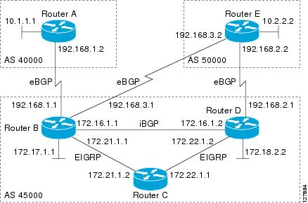
Perform this task to activate an MTR topology inside an address family using BGP. This task is configured on Router B in Figure 8 and must also be configured on Router D and Router E. In this task, a scope hierarchy is configured to apply globally and a neighbor is configured under router scope configuration mode. Under the IPv4 unicast address family, an MTR topology that applies to video traffic is activated for the specified neighbor. There is no interface configuration mode for BGP topologies.
Figure 8 BGP Network Diagram
The BGP CLI has been modified to provide backwards compatibility for pre-MTR BGP configuration and to provide a hierarchical implementation of MTR. A new configuration hierarchy, named scope, has been introduced into the BGP protocol. To implement MTR for BGP, the scope hierarchy is required, but the scope hierarchy is not limited to MTR use. The scope hierarchy introduces some new configuration modes such as router scope configuration mode. Router scope configuration mode is entered by configuring the scope command in router configuration mode, and a collection of routing tables is created when this command is entered. The following shows the hierarchy levels that are used when configuring BGP for MTR implementation:
router bgp <autonomous-system-number>
 ! Global commands
 scope {global | vrf <vrf-name>}
  ! Scoped commands
  address-family {<afi>} [<safi>]
   ! Address family specific commands
   topology {<topology-name> | base}
    ! Topology specific commands
Before using BGP to support MTR, you should be familiar with all the concepts documented in the "BGP Routing Protocol Support for MTR" section.
Prerequisites
•
•
Restrictions
•
•
•
SUMMARY STEPS
1.
2.
3.
4.
5.
6.
7.
8.
9.
10.
11.
12.
13.
14.
DETAILED STEPS
Step 1
enable
Example:Router> enable
Enables privileged EXEC mode.
•
Step 2
configure terminal
Example:Router# configure terminal
Enters global configuration mode.
Step 3
router bgp autonomous-system-number
Example:Router(config)# router bgp 45000
Enters router configuration mode to create or configure a BGP routing process.
Step 4
scope {global | vrf vrf-name}
Example:Router(config-router)# scope global
Defines the scope to the BGP routing process and enters router scope configuration mode.
•
•
•
Step 5
neighbor {ip-address | peer-group-name} remote-as autonomous-system-number
Example:Router(config-router-scope)# neighbor 172.16.1.2 remote-as 45000
Adds the IP address of the neighbor in the specified autonomous system to the multiprotocol BGP neighbor table of the local router.
Step 6
neighbor {ip-address | peer-group-name} transport {connection-mode {active | passive} | path-mtu-discovery | multi-session | single-session}
Example:Router(config-router-scope)# neighbor 172.16.1.2 transport multi-session
Enables a TCP transport session option for a BGP session.
•
•
•
•
Step 7
address-family ipv4 [mdt | multicast | unicast]
Example:Router(config-router-scope)# address-family ipv4
Specifies the IPv4 address family and enters router scope address family configuration mode.
•
•
•
•
Step 8
topology {base | topology-name}
Example:Router(config-router-scope-af)# topology VIDEO
Configures the topology instance in which BGP will route class-specific or base topology traffic, and enters router scope address family topology configuration mode.
Step 9
bgp tid number
Example:Router(config-router-scope-af-topo)# bgp tid 100
Associates a BGP routing process with the specified topology ID.
•
Step 10
neighbor ip-address activate
Example:Router(config-router-scope-af-topo)#
neighbor 172.16.1.2 activateEnables the BGP neighbor to exchange prefixes for the NSAP address family with the local router.
Note
Step 11
neighbor {ip-address | peer-group-name}
translate-topology numberExample:Router(config-router-scope-af-topo)# neighbor 172.16.1.2 translate-topology 200
(Optional) Configures BGP to install routes from a topology on another router to a topology on the local router.
•
Step 12
end
Example:Router(config-router-scope-af-topo)# end
(Optional) Exits router scope address family topology configuration mode and returns to privileged EXEC mode.
Step 13
clear ip bgp topology {* | topology-name} {as-number | dampening [network-address [net- work-mask]] | flap-statistics [network-address [network-mask]] | peer-group peer-group-name | table-map | update-group [number | ip-ad- dress]} [in [prefix-filter] | out | soft [in [prefix-filter] | out]]
Example:Router# clear ip bgp topology VIDEO 45000
Resets BGP neighbor sessions under a specified topology or all topologies.
Step 14
show ip bgp topology {* | topology} summary
Example:Router# show ip bgp topology VIDEO summary
(Optional) Displays BGP information about a topology.
•
Note
Examples
The following example shows summary output for the show ip bgp topology command and the VIDEO topology:
Router# show ip bgp topology VIDEO summaryBGP router identifier 192.168.3.1, local AS number 45000BGP table version is 1, main routing table version 1Neighbor V AS MsgRcvd MsgSent TblVer InQ OutQ Up/Down State/PfxRcd172.16.1.2 4 45000 289 289 1 0 0 04:48:44 0192.168.3.2 4 50000 3 3 1 0 0 00:00:27 0What to Do Next
Repeat this task for every topology that you want to enable, and repeat this configuration on all neighbor routers that are to use the topologies. If you want to import routes from one MTR topology to another on the same router, proceed to the next task.
Importing Routes from an MTR Topology Using BGP
Perform this task to import routes from one MTR topology to another on the same router, when multiple topologies are configured on the same router. In this task, a prefix list is defined to permit prefixes from the 10.2.2.0 network, and this prefix list is used with a route map to filter routes moved from the imported topology. A global scope is configured, address family IPv4 is entered, the VIDEO topology is specified, the VOICE topology is imported, and the routes are filtered using the route map named 10NET.
Prerequisites
•
•
Restrictions
•
•
•
SUMMARY STEPS
1.
2.
3.
4.
5.
6.
7.
8.
9.
10.
11.
12.
DETAILED STEPS
Configuring an MTR Topology in Interface Configuration Mode
Perform this task to configure an MTR topology in interface configuration mode. The configuration of an MTR topology in interface configuration mode allows you to enable or disable MTR on a per-interface basis. By default, a class-specific topology does not include any interfaces.
Individual interfaces can be included or excluded by configuring the topology (interface) command. The address family and topology (base or class-specific) are specified when entering this command. The subaddress family can be optionally specified. If no subaddress family is specified, the unicast subaddress family is used by default.
Note
All interfaces on a router are included globally in a topology by entering the all-interfaces command in routing topology configuration mode. Per-interface topology configuration applied with the topology (interface) command overrides global interface configuration.
Per-Interface Routing
IGP routing and metric configurations can be applied in interface topology configuration mode. Per interface metrics and routing behaviors can be configured for each IGP. Interface configuration mode IGP commands are documented in the configuration section for each routing protocol.
Prerequisites
A topology must be defined globally before per-interface topology configuration can be configured.
Restrictions
Only the IPv4 address family is currently supported.
SUMMARY STEPS
1.
2.
3.
4.
5.
DETAILED STEPS
What to Do Next
The next three tasks show how to activate an MTR topology and various routing protocol features in interface configuration mode. Proceed to the next task for more information.
Activating an MTR Topology in Interface Configuration Mode Using OSPF
Perform this task to configure OSPF features used in MTR in interface configuration mode. Configuring a topology in interface configuration mode allows you to enable or disable MTR on per-interface basis. By default, a class-specific topology does not include any interfaces.
OSPF Interface Topology Configuration
Interface mode OSPF configurations for a class-specific topology are applied in interface topology configuration mode. In this mode, you can configure an interface cost or disable OSPF routing on the interface without removing the interface from the global topology configuration.
Prerequisites
A topology must be defined globally before per-interface topology configuration can be configured.
Restrictions
Only the IPv4 address family is currently supported.
SUMMARY STEPS
1.
2.
3.
4.
5.
6.
7.
8.
DETAILED STEPS
Activating an MTR Topology in Interface Configuration Mode Using EIGRP
Perform this task to configure EIGRP features used in MTR in interface configuration mode. Configuring a topology in interface configuration mode allows you enable or disable MTR on per-interface basis. By default, a class-specific topology does not include any interfaces.
EIGRP Interface Topology Configuration
Interface mode EIGRP configurations for a class-specific topology are applied in interface topology configuration mode. In this mode, you can configure various EIGRP features.
Prerequisites
IP routing and CEF must be enabled.
Restrictions
Only the IPv4 address family is currently supported.
SUMMARY STEPS
1.
2.
3.
4.
5.
6.
7.
8.
9.
10.
11.
DETAILED STEPS
Activating an MTR Topology in Interface Configuration Mode Using IS-IS
Perform this task to configure IS-IS features used in MTR in interface configuration mode. Configuring a topology in interface configuration mode allows you to enable or disable MTR on per-interface basis. By default, a class-specific topology does not include any interfaces.
IS-IS Interface Topology Configuration
Interface mode IS-IS configurations for a class-specific topology are applied in interface topology configuration mode. By using the interface configuration mode, you can configure an interface cost or disable IS-IS routing on the interface without removing the interface from the global topology configuration.
Prerequisites
A topology must be defined globally before per-interface topology configuration can be configured.
SUMMARY STEPS
1.
2.
3.
4.
5.
6.
7.
8.
9.
DETAILED STEPS
Configuring SNMP Support for MTR
This section contains the following tasks:
•
•
•
SNMP Context Mapping for MTR
Context-based Simple Network Management Protocol (SNMP) support has been integrated into Cisco IOS software. SNMP support for MTR leverages context-based SNMP to extend support for existing MIBs from representing the management information for just the base topology to representing the same information for multiple topologies.
The SNMP agent software component on the router can be configured to pass a context string to existing MIB access functions. Network management applications can provide these context strings in SNMP transactions to direct those transactions to a specific virtual private network (VPN) routing and forwarding (VRF) instance, a specific topology, and/or routing protocol instance. The SNMP infrastructure on the receiving router verifies that a context string is defined for the router, and that the accompanying internal identifier is defined for that context string, before passing on the context string and internal identifier to the MIB access function.
Associating an SNMP Context with a VRF for MTR
In the following task, the context name will be associated with the specified VRF.
Prerequisites
•
SUMMARY STEPS
1.
2.
3.
4.
5.
6.
DETAILED STEPS
Associating an SNMP Context with a Data Topology for MTR
In the following task, the context name will be associated with the specified topology.
Prerequisites
•
SUMMARY STEPS
1.
2.
3.
4.
5.
6.
7.
DETAILED STEPS
Associating an SNMP Context with a Routing Protocol for MTR
In the following task, the context name will be associated with the specified routing protocol instance.
Prerequisites
•
SUMMARY STEPS
1.
2.
3.
4.
5.
6.
7.
8.
9.
DETAILED STEPS
Enabling and Monitoring MTR Topology Statistics Accounting
This section contains the following tasks related to managing MTR statistics:
•
•
Enabling Topology Statistics Accounting for MTR
This section describes how to enable topology statistics accounting on all of the interfaces in the global address family for all IPv4 unicast topologies in the default VRF instance and how to enable topology accounting for all IPv4 unicast topologies in the VRF instance associated with a particular interface.
Prerequisites
•
SUMMARY STEPS
1.
2.
3.
4.
5.
6.
7.
8.
DETAILED STEPS
Monitoring Interface and Topology IP Traffic Statistics for MTR
This section describes how to display and clear IP traffic statistics.
SUMMARY STEPS
1.
2.
3.
4.
5.
DETAILED STEPS
Testing Network Connectivity for MTR
Ping and traceroute have been enhanced to support MTR in Cisco IOS Release 12.2(33)SRB. You can configure a standard or extended ping using the topology name in place of a hostname or IP address. Traceroute has been similarly enhanced.
SUMMARY STEPS
1.
2.
3.
DETAILED STEPS
Configuration Examples for Multi-Topology Routing
This section provides the following example configurations for MTR:
•
•
•
•
•
•
•
•
•
•
•
•
•
•
•
Unicast Topology for MTR: Examples
The section contains the following configuration examples:
•
•
•
Global Interface Configuration Example
The following example creates a topology instance named VOICE. This topology is configured to use all operational interfaces on the router. Per the default forwarding rule (strict), only packets destined for routes in the VOICE topology RIB are forwarded. Packets that do not have a topology-specific forwarding entry are dropped.
global-address-family ipv4topology VOICEall-interfacesendIncremental Forwarding Configuration Example
The following example creates a topology instance named VIDEO. This topology is configured to accept and install a maximum of 1000 routes in the VIDEO topology RIB. Incremental forwarding mode is configured so that the router forwards packets over the base topology if no forwarding entry is found in the class-specific RIB.
global-address-family ipv4topology VIDEOforward-basemaximum routes 1000 90endUnicast Topology Verification Example
The output of the show topology detail command displays information about class-specific and base topologies. This information includes the address family, associated interfaces, interface and topology status, topology name, and associated VRF.
Router# show topology detailTopology: baseAddress-family: ipv4Associated VPN VRF is defaultTopology state is UPAssociated interfaces:Ethernet0/0, operation state: UPEthernet0/1, operation state: DOWNEthernet0/2, operation state: DOWNEthernet0/3, operation state: DOWNLoopback0, operation state: UPTopology: VIDEOAddress-family: ipv4Associated VPN VRF is defaultTopology state is UPTopology fallback is enabledTopology maximum route limit 1000, warning limit 90% (900)Associated interfaces:Topology: VOICEAddress-family: ipv4Associated VPN VRF is defaultTopology state is UPTopology is enabled on all interfacesAssociated interfaces:Ethernet0/0, operation state: UPEthernet0/1, operation state: DOWNEthernet0/2, operation state: DOWNEthernet0/3, operation state: DOWNLoopback0, operation state: UPTopology: baseAddress-family: ipv4 multicastAssociated VPN VRF is defaultTopology state is DOWNRoute Replication Enabled:from unicast allAssociated interfaces:Multicast Topology for MTR: Examples
This section contains the following configuration examples:
•
•
•
Route Replication Configuration Example
The following example enables multicast support for MTR and configures a separate multicast topology:
ip multicast-routingip multicast rpf multitopology!global-address-family ipv4 multicasttopology baseendThe following example configures the multicast topology to replicate OSPF routes from the VOICE topology. The routes are filtered through the BLUE route map before they are installed in the multicast routing table.
ip multicast-routingip multicast rpf multitopology!access-list 1 permit 192.168.1.0 0.0.0.255!route-map BLUEmatch ip address 1exit!global-address-family ipv4 multicasttopology baseroute-replicate from unicast topology VOICE ospf route-map BLUEUsing a Unicast RIB for Multicast RPF Configuration Example
The following example configures the multicast topology to perform RPF calculations on routes in the VIDEO topology RIB to build multicast distribution trees:
ip multicast-routingip multicast rpf multitopology!global-address-family ipv4 multicasttopology baseuse-topology unicast VIDEOendMulticast Verification Example
The following example shows that the multicast topology is configured to replicate routes from the RIB of the VOICE topology:
Router# show topology detailTopology: baseAddress-family: ipv4Associated VPN VRF is defaultTopology state is UPAssociated interfaces:Ethernet0/0, operation state: UPEthernet0/1, operation state: DOWNEthernet0/2, operation state: DOWNEthernet0/3, operation state: DOWNLoopback0, operation state: UPTopology: VIDEOAddress-family: ipv4Associated VPN VRF is defaultTopology state is UPTopology fallback is enabledTopology maximum route limit 1000, warning limit 90% (900)Associated interfaces:Topology: VOICEAddress-family: ipv4Associated VPN VRF is defaultTopology state is UPTopology is enabled on all interfacesAssociated interfaces:Ethernet0/0, operation state: UPEthernet0/1, operation state: DOWNEthernet0/2, operation state: DOWNEthernet0/3, operation state: DOWNLoopback0, operation state: UPTopology: baseAddress-family: ipv4 multicastAssociated VPN VRF is defaultTopology state is DOWNMulticast multi-topology mode is enabled.Route Replication Enabled:from unicast topology VOICE all route-map BLUEAssociated interfaces:MTR Traffic Classification: Examples
The following example configures classification and activates MTR for two topologies:
global-address-family ipv4topology VOICEall-interfacesexittopology VIDEOforward-basemaximum routes 1000 90exitexitclass-map match-any VOICE-CLASSmatch ip dscp 9exitclass-map match-any VIDEO-CLASSmatch ip dscp af11exitpolicy-map type class-routing ipv4 unicast MTRclass VOICE-CLASSselect-topology VOICEexitclass VIDEO-CLASSselect-topology VIDEOexitexitglobal-address-family ipv4service-policy type class-routing MTRendThe following example displays detailed information about the VOICE and VIDEO topologies:
Router# show topology detailTopology: baseAddress-family: ipv4Associated VPN VRF is defaultTopology state is UPAssociated interfaces:Ethernet0/0, operation state: UPEthernet0/1, operation state: DOWNEthernet0/2, operation state: DOWNEthernet0/3, operation state: DOWNLoopback0, operation state: UPTopology: VIDEOAddress-family: ipv4Associated VPN VRF is defaultTopology state is UPTopology fallback is enabledTopology maximum route limit 1000, warning limit 90% (900)Associated interfaces:Topology: VOICEAddress-family: ipv4Associated VPN VRF is defaultTopology state is UPTopology is enabled on all interfacesAssociated interfaces:Ethernet0/0, operation state: UPEthernet0/1, operation state: DOWNEthernet0/2, operation state: DOWNEthernet0/3, operation state: DOWNLoopback0, operation state: UPTopology: baseAddress-family: ipv4 multicastAssociated VPN VRF is defaultTopology state is DOWNMulticast multi-topology mode is enabled.Route Replication Enabled:from unicast topology VOICE all route-map BLUEAssociated interfaces:Ethernet0/0, operation state: UPEthernet0/1, operation state: DOWNEthernet0/2, operation state: DOWNEthernet0/3, operation state: DOWNLoopback0, operation state: UPThe following example displays the classification values for the VOICE and VIDEO topologies:
Router# show mtm tableMTM Table for VRF: default, ID:0Topology Address Family Associated VRF Topo-IDbase ipv4 default 0VOICE ipv4 default 2051Classifier: ClassID:3DSCP: cs1DSCP: 9VIDEO ipv4 default 2054Classifier: ClassID:4DSCP: af11Activating an MTR Topology Using OSPF: Examples
The following example configures the VOICE topology in an OSPF routing process and sets the priority of the VOICE topology to the highest priority:
router ospf 1address-family ipv4topology VOICE tid 10priority 127endIn the following example, the show ip ospf command is used with the topology-info and topology keywords to display OSPF information about the topology named VOICE.
Router# show ip ospf 1 topology-info topology VOICEOSPF Router with ID (1.0.0.1) (Process ID 1)VOICE Topology (MTID 66)Topology priority is 64Redistributing External Routes from,isisNumber of areas transit capable is 0Initial SPF schedule delay 5000 msecsMinimum hold time between two consecutive SPFs 10000 msecsMaximum wait time between two consecutive SPFs 10000 msecsArea BACKBONE(0) (Inactive)SPF algorithm last executed 16:45:18.984 agoSPF algorithm executed 3 timesArea ranges areArea 1SPF algorithm last executed 00:00:21.584 agoSPF algorithm executed 1 timesArea ranges areActivating an MTR Topology Using EIGRP: Examples
The following example activates the VIDEO topology using EIGRP:
router eigrp MTRaddress-family ipv4 autonomous-system 1network 10.0.0.0 0.0.0.255topology VIDEO tid 10redistribute connectedendThe following example displays the status of routing protocols configured in the VIDEO topology. EIGRP information is shown in the output.
Router# show ip protocols topology VIDEO*** IP Routing is NSF aware ***Routing Protocol is "eigrp 1"Outgoing update filter list for all interfaces is not setIncoming update filter list for all interfaces is not setDefault networks flagged in outgoing updatesDefault networks accepted from incoming updatesEIGRP metric weight K1=1, K2=0, K3=1, K4=0, K5=0EIGRP maximum hopcount 100EIGRP maximum metric variance 1Redistributing: eigrp 1EIGRP graceful-restart disabledEIGRP NSF-aware route hold timer is 240sTopologies : 100(VOICE) 0(base)Automatic network summarization is in effectMaximum path: 4Routing for Networks:Routing Information Sources:Gateway Distance Last UpdateDistance: internal 90 external 170The following example shows the EIGRP routing table configured under the VIDEO topology:
Router# show ip eigrp topology VIDEOEIGRP-IPv4 Topology Table for AS(1)/ID(1.1.1.2) Routing Table: VOICECodes: P - Passive, A - Active, U - Update, Q - Query, R - Reply,r - reply Status, s - sia StatusP 10.1.1.0/24, 1 successors, FD is 281600via Connected, Ethernet0/0Activating an MTR Topology Using IS-IS: Examples
The following example configures the MTR topologies DATA and VIDEO and configures IS-IS support for MTR. The DATA and VIDEO topologies are enabled on three IS-IS neighbors in a network.
Router1
global-address-family ipv4topology DATAtopology VOICEendinterface Ethernet 0/0ip address 192.168.128.2 255.255.255.0ip router isistopology ipv4 DATAisis topology disabletopology ipv4 VOICEendrouter isisnet 33.3333.3333.3333.00metric-style wideaddress-family ipv4topology DATA tid 100topology VOICE tid 200endRouter2
global-address-family ipv4topology DATAtopology VOICEall-interfacesforward-basemaximum routes 1000 warning-onlyshutdownendinterface Ethernet 0/0ip address 192.168.128.1 255.255.255.0ip router isistopology ipv4 DATAisis topology disabletopology ipv4 VOICEendinterface Ethernet 1/0ip address 192.168.130.1 255.255.255.0ip router isistopology ipv4 DATAisis topology disabletopology ipv4 VOICEendrouter isisnet 32.3232.3232.3232.00metric-style wideaddress-family ipv4topology DATA tid 100topology VOICE tid 200endRouter 3
global-address-family ipv4topology DATAtopology VOICEall-interfacesforward-basemaximum routes 1000 warning-onlyshutdownendinterface Ethernet 1/0ip address 192.168.131.1 255.255.255.0ip router isistopology ipv4 DATAisis topology disabletopology ipv4 VOICEendrouter isisnet 31.3131.3131.3131.00metric-style wideaddress-family ipv4topology DATA tid 100topology VOICE tid 200endEntering the show isis neighbors detail command verifies topology translation with the IS-IS neighbor Router1:
Router# show isis neighbors detailSystem Id Type Interface IP Address State Holdtime Circuit IdR1 L2 Et0/0 192.168.128.2 UP 28 R5.01Area Address(es): 33SNPA: aabb.cc00.1f00State Changed: 00:07:05LAN Priority: 64Format: Phase VRemote TID: 100, 200Local TID: 100, 200Activating an MTR Topology Using BGP: Examples
This section contains the following configuration examples:
•
•
BGP Topology Translation Configuration
The following example configures BGP in the VIDEO topology and configures topology translation with the 192.168.2.2 neighbor:
router bgp 45000scope globalneighbor 172.16.1.1 remote-as 50000neighbor 192.168.2.2 remote-as 55000neighbor 172.16.1.1 transport multi-sessionneighbor 192.168.2.2 transport multi-sessionaddress-family ipv4topology VIDEObgp tid 100neighbor 172.16.1.1 activateneighbor 192.168.2.2 activateneighbor 192.168.2.2 translate-topology 200endclear ip bgp topology VIDEO 50000BGP Scope Global and VRF Configuration
The following example shows how to configure a global scope for a unicast topology and also for a multicast topology. After exiting the router scope configuration mode, a scope is configured for the VRF named DATA.
router bgp 45000scope globalbgp default ipv4-unicastneighbor 172.16.1.2 remote-as 45000neighbor 192.168.3.2 remote-as 50000address-family ipv4 unicasttopology VOICEbgp tid 100neighbor 172.16.1.2 activateexitaddress-family ipv4 multicasttopology baseneighbor 192.168.3.2 activateexitexitexitscope vrf DATAneighbor 192.168.1.2 remote-as 40000address-family ipv4neighbor 192.168.1.2 activateendBGP Topology Verification
The following example shows summary output for the show ip bgp topology command. Information is displayed about BGP neighbors configured to use the MTR topology named VIDEO.
Router# show ip bgp topology VIDEO summaryBGP router identifier 192.168.3.1, local AS number 45000BGP table version is 1, main routing table version 1Neighbor V AS MsgRcvd MsgSent TblVer InQ OutQ Up/Down State/PfxRcd172.16.1.2 4 45000 289 289 1 0 0 04:48:44 0192.168.3.2 4 50000 3 3 1 0 0 00:00:27 0The following partial output displays BGP neighbor information under the VIDEO topology:
Router# show ip bgp topology VIDEO neighbors 172.16.1.2BGP neighbor is 172.16.1.2, remote AS 45000, internal linkBGP version 4, remote router ID 192.168.2.1BGP state = Established, up for 04:56:30Last read 00:00:23, last write 00:00:21, hold time is 180, keepalive interval is 60 secondsNeighbor sessions:1 active, is multisession capableNeighbor capabilities:Route refresh: advertised and received(new)Message statistics, state Established:InQ depth is 0OutQ depth is 0Sent RcvdOpens: 1 1Notifications: 0 0Updates: 0 0Keepalives: 296 296Route Refresh: 0 0Total: 297 297Default minimum time between advertisement runs is 0 secondsFor address family: IPv4 Unicast topology VIDEOSession: 172.16.1.2 session 1BGP table version 1, neighbor version 1/0Output queue size : 0Index 1, Offset 0, Mask 0x21 update-group memberTopology identifier: 100...Address tracking is enabled, the RIB does have a route to 172.16.1.2Address tracking requires at least a /24 route to the peerConnections established 1; dropped 0Last reset neverTransport(tcp) path-mtu-discovery is enabledConnection state is ESTAB, I/O status: 1, unread input bytes: 0Minimum incoming TTL 0, Outgoing TTL 255Local host: 172.16.1.1, Local port: 11113Foreign host: 172.16.1.2, Foreign port: 179...Importing Routes from an MTR Topology Using BGP: Example
The following example shows how to configure an access list to be used by a route map named BLUE to filter routes imported from the MTR topology named VOICE. Only routes with the prefix 192.168.1.0 are imported.
access-list 1 permit 192.168.1.0 0.0.0.255route-map BLUEmatch ip address 1exitrouter bgp 50000scope globalneighbor 10.1.1.2 remote-as 50000neighbor 172.16.1.1 remote-as 60000address-family ipv4topology VIDEObgp tid 100neighbor 10.1.1.2 activateneighbor 172.16.1.1 activateimport topology VOICE route-map BLUEendclear ip bgp topology VIDEO 50000MTR Topology in Interface Configuration Mode: Examples
The following example disables the VOICE topology on Ethernet interface 0/0.
interface Ethernet 0/0topology ipv4 VOICE disableMTR OSPF Topology in Interface Configuration Mode: Examples
The following example disables OSPF routing on interface Ethernet 0/0 without removing the interface from the global topology configuration:
interface Ethernet 0/0topology ipv4 VOICEip ospf cost 100ip ospf topology disableendIn the following example, the show ip ospf interface command is used with the topology keyword to display information about the topologies configured for OSPF in interface configuration mode.
Router# show ip ospf 1 interface topology VOICEVOICE Topology (MTID 66)Serial3/0 is up, line protocol is upInternet Address 10.0.0.5/30, Area 1Process ID 1, Router ID 44.44.44.44, Network Type POINT_TO_POINTTopology-MTID Cost Disabled Shutdown Topology Name4 77 no no grcTransmit Delay is 1 sec, State POINT_TO_POINTTimer intervals configured, Hello 10, Dead 40, Wait 40, Retransmit 5oob-resync timeout 40Hello due in 00:00:05Supports Link-local Signaling (LLS)Cisco NSF helper support enabledIETF NSF helper support enabledIndex 1/4, flood queue length 0Next 0x0(0)/0x0(0)Last flood scan length is 1, maximum is 1Last flood scan time is 0 msec, maximum is 0 msecNeighbor Count is 1, Adjacent neighbor count is 1Adjacent with neighbor 2.2.2.2Suppress hello for 0 neighbor(s)In the following example, the show ip ospf interface command is used with the brief and topology keywords to display information about the topologies configured for OSPF in interface configuration mode.
Router# show ip ospf 1 interface brief topology VOICEVOICE Topology (MTID 66)Interface PID Area IP Address/Mask Cost State Nbrs F/CSe3/0 1 1 10.0.0.5/30 1 UP 0/0Se2/0 1 1 10.0.0.1/30 1 UP 0/0MTR EIGRP Topology in Interface Configuration Mode: Examples
The following example sets the EIGRP delay calculation on interface Ethernet 0/0 to 100 milliseconds:
interface Ethernet 0/0topology ipv4 VOICEeigrp 1 delay 100000eigrp 1 next-hop-selfeigrp 1 shutdowneigrp 1 split-horizoneigrp 1 summary-address 10.1.1.0 0.0.0.255endThe following example displays EIGRP information about interfaces in the VOICE topology:
Router# show ip eigrp topology VOICE interfacesEIGRP-IPv4 interfaces for process 1Xmit Queue Mean Pacing Time Multicast PendingInterface Peers Un/Reliable SRTT Un/Reliable Flow Timer RoutesEt0/0 1 0/0 20 0/2 0 0The following example displays EIGRP information about links in the VOICE topology:
Router# show ip eigrp topology VOICE detail-linksEIGRP-IPv4 Topology Table for AS(1)/ID(1.1.1.1) Routing Table: VOICECodes: P - Passive, A - Active, U - Update, Q - Query, R - Reply,r - reply Status, s - sia StatusP 10.1.1.0/24, 1 successors, FD is 25856000, serno 5via Connected, Ethernet0/0MTR IS-IS Topology in Interface Configuration Mode: Examples
The following example prevents the IS-IS process from advertising interface Ethernet 1/0 as part of the DATA topology:
interface Ethernet 1/0ip address 192.168.130.1 255.255.255.0ip router isistopology ipv4 DATAisis topology disabletopology ipv4 VOICEendSNMP Support for MTR: Examples
In the following example, the context string "context-vrfA" is configured to be associated with vrfA and will be passed on to the MIB access function during SNMP transactions:
snmp-server community publicip vrf vrfAsnmp context context-vrfAexitIn the following example, the context string "context-voice" is configured to be associated with the data topology named voice and will be passed on to the MIB access function during SNMP transactions:
global-address-family ipv4topology voicesnmp context context-voiceexitIn the following example, the context string "context-ospf" and "context-voice" are configured to be associated with the OSPF process and topology named voice and will be passed on to the MIB access function during SNMP transactions:
router ospf 3snmp context context-ospfaddress-family ipv4topology voice tid 10snmp context ospf-voiceendThe following example shows how the context strings are mapped to the specified VRF, address family, topology, or protocol instance:
Router# show snmp context mappingContext: ospf-voiceVRF Name:Address Family Name: ipv4Topology Name: voiceProtocol Instance: OSPF-3 RouterContext: context-ospfVRF Name:Address Family Name:Topology Name:Protocol Instance: OSPF-3 RouterContext: context-vrfAVRF Name: vrfAAddress Family Name:Topology Name:Protocol Instance:Context: context-voiceVRF Name:Address Family Name: ipv4Topology Name: voiceProtocol Instance:Monitoring Interface and Topology IP Traffic Statistics: Examples
In the following example, the show ip interface command is used with the type number arguments to display IP traffic statistics for the Fast Ethernet interface 1/10 :
Router# show ip interface FastEthernet 1/10 statsFastEthernet1/105 minutes input rate 0 bits/sec, 0 packet/sec,5 minutes output rate 0 bits/sec, 0 packet/sec,201 packets input, 16038 bytes588 packets output, 25976 bytesIn this example, the show ip traffic command is used with the topology instance keyword and argument to display statistics related to a particular topology:
Router# show ip traffic topology VOICETopology: VOICE5 minute input rate 0 bits/sec, 0 packet/sec,5 minute output rate 0 bits/sec, 0 packet/sec,100 packets input, 6038 bytes,88 packets output, 5976 bytes.Testing Network Connectivity for MTR: Examples
The following example sends a ping to the 10.1.1.2 neighbor in the VOICE topology:
Router# ping topology VOICE 10.1.1.2Type escape sequence to abort.Sending 5, 100-byte ICMP Echos to 10.1.1.2, timeout is 2 seconds:!!!!!Success rate is 100 percent (5/5), round-trip min/avg/max = 1/1/4 msThe following example traces the 10.1.1.4 host in the VOICE topology:
Router# traceroute VOICE ip 10.1.1.4Type escape sequence to abort.Tracing the route to 10.1.1.41 10.1.1.2 4 msec * 0 msec2 10.1.1.3 4 msec * 2 msec3 10.1.1.4 4 msec * 4 msecAdditional References
The following sections provide references related to MTR.
Related Documents
MTR commands: complete command syntax, command modes, command history, defaults, usage guidelines, and examples
IP routing protocol commands: complete command syntax, command modes, command history, defaults, usage guidelines, and examples
Cisco IOS IP Routing: BGP Command Reference
Cisco IOS IP Routing: EIGRP Command Reference
Cisco IOS IP Routing: ISIS Command Reference
IP multicast commands: complete command syntax, command modes, command history, defaults, usage guidelines, and examples
QoS commands: complete command syntax, command modes, command history, defaults, usage guidelines, and examples
IP routing protocols concepts and tasks
Cisco IOS IP Routing: BGP Configuration Guide
Cisco IOS IP Routing: EIGRP Configuration Guide
Cisco IOS IP Routing: ISIS Configuration Guide
IP multicast concepts and tasks
QoS concepts and tasks
Configuring Multitopology IS-IS for IPv6
"Implementing IS-IS for IPv6," Cisco IOS IPv6 Configuration Guide
Cisco IOS In Service Software Upgrade Process
Cisco IOS In Service Software Upgrade Process module
Standards
No new or modified standards are supported by this feature, and support for existing standards has not been modified by this feature.
—
MIBs
RFCs
No new or modified RFCs are supported by this feature, and support for existing RFCs has not been modified by this feature.
—
Technical Assistance
Feature Information for Multi-Topology Routing
Table 1 lists the features in this module and provides links to specific configuration information. Only features that were introduced or modified in 12.2(33)SRB or a later release appear in the table.
Not all commands may be available in your Cisco IOS software release. For release information about a specific command, see the command reference documentation.
Use Cisco Feature Navigator to find information about platform support and software image support. Cisco Feature Navigator enables you to determine which Cisco IOS and Catalyst OS software images support a specific software release, feature set, or platform. To access Cisco Feature Navigator, go to http://www.cisco.com/go/cfn. An account on Cisco.com is not required.
Note
Table 1 Feature Information for Multi-Topology Routing
Multi-Topology Routing
12.2(33)SRB
MTR introduces the capability to configure service differentiation through class-based forwarding. MTR provides multiple logical topologies over a single physical network. Service differentiation can be achieved by forwarding different traffic types over different logical topologies that could take different paths to the same destination. MTR can be used, for example, to define separate topologies for voice, video, and data traffic classes.
BGP Support for MTR
12.2(33)SRB
This feature provides BGP support for multiple logical topologies over a single physical network.
The following sections provide information about this feature:
•
•
•
•
EIGRP Support for MTR
12.2(33)SRB
This feature provides EIGRP support for multiple logical topologies over a single physical network.
The following sections provide information about this feature:
•
•
•
•
•
IS-IS Support for MTR
12.2(33)SRB
This feature provides IS-IS support for multiple logical topologies over a single physical network.
The following sections provide information about this feature:
•
•
•
•
•
ISSU—MTR
12.2(33)SRB1
All protocols and applications that support MTR and also support ISSU have extended their ISSU support to include the MTR functionality.
The following section provides information about this feature:
OSPF Support for MTR
12.2(33)SRB
This feature provides OSPF support for multiple logical topologies over a single physical network.
The following sections provide information about this feature:
•
•
•
•
•
QoS/MQC Support for MTR
12.2(33)SRB
This feature enables MTR traffic classification. Traffic classification is used to associate different classes of traffic with different topologies when multiple topologies are configured on the same router. A subset of DSCP bits is used to encode classification values in the IP packet header and mark the packet for classification. When MTR traffic classification is enabled, MTR is activated and ready for the routing protocols to start contributing to the topologies.
The following sections provide information about this feature:
•
SNMP Support for MTR
12.2(33)SRB
Context-based Simple Network Management Protocol (SNMP) functionality has been integrated into Cisco IOS software and can be used to support MTR. SNMP support for MTR leverages context-based SNMP to extend support for existing MIBs from representing the management information for just the base topology to representing the same information for multiple topologies.
The following sections provide information about this feature:
•
•
Glossary
base topology—The entire network for which the usual set of routes are calculated. This topology is the same as the default global routing table that exists today without MTR being used.
class-specific topology—New topologies that are defined over and above the existing base topology; each class-specific topology is represented by its own RIB and FIB.
classification—Selection and matching of traffic that needs to be provided with a different treatment based on its mark. Classification is a read-only operation.
DSCP—DiffServ Code Point. Six bits in the ToS. (Two bits are now used for Explicit Congestion Notification.) These are the bits used to mark the packet.
incremental forwarding mode—Incremental forwarding mode is designed to support transitional or incremental deployment of MTR, where there are routers in the network that are not MTR enabled. In this mode, the router will look for a forwarding entry first in the class-specific FIB. If an entry is not found, the router will then look for the longest match in the base topology FIB. If an entry is found in the base topology FIB, the packet will be forwarded on the base topology. If a forwarding entry is not found in the base topology FIB, the packet is dropped.
marking—Setting a value in the packet or frame. Marking is a read and write operation.
multi-topology—Multi-topology means that each topology will route/forward a subset of the traffic as defined by the classification criteria.
NLRI—Network Layer Reachability Information.
strict forwarding mode—Strict forwarding mode is the default forwarding mode for MTR. Only routes in the topology specific routing table are considered. Among these, the longest match for the destination address is used. If no route containing the destination address can be found in the topology specific table, the packet is dropped.
TID—Topology Identifier. Each topology is configured with a unique topology ID. The topology ID is configured under the routing protocol and is used to identify and group NLRI for each topology in updates for a given protocol.

Any Internet Protocol (IP) addresses used in this document are not intended to be actual addresses. Any examples, command display output, and figures included in the document are shown for illustrative purposes only. Any use of actual IP addresses in illustrative content is unintentional and coincidental.
© 2007 Cisco Systems, Inc. All rights reserved.
 Feedback