FlexPod Datacenter with Oracle 19c RAC Databases on Cisco UCS and NetApp AFF with NVMe over FibreChannel
Available Languages
Bias-Free Language
The documentation set for this product strives to use bias-free language. For the purposes of this documentation set, bias-free is defined as language that does not imply discrimination based on age, disability, gender, racial identity, ethnic identity, sexual orientation, socioeconomic status, and intersectionality. Exceptions may be present in the documentation due to language that is hardcoded in the user interfaces of the product software, language used based on RFP documentation, or language that is used by a referenced third-party product. Learn more about how Cisco is using Inclusive Language.
- US/Canada 800-553-2447
- Worldwide Support Phone Numbers
- All Tools
 Feedback
 Feedback

FlexPod Datacenter with Oracle 19c RAC Databases on Cisco UCS and NetApp AFF with NVMe over FibreChannel
Deployment Guide for Oracle 19c RAC Databases on Cisco Unified Computing System and NetApp AFF A800 Storage using Modern SANs on NVMe/FC
Published: April 2021

In partnership with
![]()
About the Cisco Validated Design Program
The Cisco Validated Design (CVD) program consists of systems and solutions designed, tested, and documented to facilitate faster, more reliable, and more predictable customer deployments. For more information, go to:
http://www.cisco.com/go/designzone.
ALL DESIGNS, SPECIFICATIONS, STATEMENTS, INFORMATION, AND RECOMMENDATIONS (COLLECTIVELY, "DESIGNS") IN THIS MANUAL ARE PRESENTED "AS IS," WITH ALL FAULTS. CISCO AND ITS SUPPLIERS DISCLAIM ALL WARRANTIES, INCLUDING, WITHOUT LIMITATION, THE WARRANTY OF MERCHANTABILITY, FITNESS FOR A PARTICULAR PURPOSE AND NONINFRINGEMENT OR ARISING FROM A COURSE OF DEALING, USAGE, OR TRADE PRACTICE. IN NO EVENT SHALL CISCO OR ITS SUPPLIERS BE LIABLE FOR ANY INDIRECT, SPECIAL, CONSEQUENTIAL, OR INCIDENTAL DAMAGES, INCLUDING, WITHOUT LIMITATION, LOST PROFITS OR LOSS OR DAMAGE TO DATA ARISING OUT OF THE USE OR INABILITY TO USE THE DESIGNS, EVEN IF CISCO OR ITS SUPPLIERS HAVE BEEN ADVISED OF THE POSSIBILITY OF SUCH DAMAGES.
THE DESIGNS ARE SUBJECT TO CHANGE WITHOUT NOTICE. USERS ARE SOLELY RESPONSIBLE FOR THEIR APPLICATION OF THE DESIGNS. THE DESIGNS DO NOT CONSTITUTE THE TECHNICAL OR OTHER PROFESSIONAL ADVICE OF CISCO, ITS SUPPLIERS OR PARTNERS. USERS SHOULD CONSULT THEIR OWN TECHNICAL ADVISORS BEFORE IMPLEMENTING THE DESIGNS. RESULTS MAY VARY DEPENDING ON FACTORS NOT TESTED BY CISCO.
CCDE, CCENT, Cisco Eos, Cisco Lumin, Cisco Nexus, Cisco StadiumVision, Cisco TelePresence, Cisco WebEx, the Cisco logo, DCE, and Welcome to the Human Network are trademarks; Changing the Way We Work, Live, Play, and Learn and Cisco Store are service marks; and Access Registrar, Aironet, AsyncOS, Bringing the Meeting To You, Catalyst, CCDA, CCDP, CCIE, CCIP, CCNA, CCNP, CCSP, CCVP, Cisco, the Cisco Certified Internetwork Expert logo, Cisco IOS, Cisco Press, Cisco Systems, Cisco Systems Capital, the Cisco Systems logo, Cisco Unified Computing System (Cisco UCS), Cisco UCS B-Series Blade Servers, Cisco UCS C-Series Rack Servers, Cisco UCS S-Series Storage Servers, Cisco UCS Manager, Cisco UCS Management Software, Cisco Unified Fabric, Cisco Application Centric Infrastructure, Cisco Nexus 9000 Series, Cisco Nexus 7000 Series. Cisco Prime Data Center Network Manager, Cisco NX-OS Software, Cisco MDS Series, Cisco Unity, Collaboration Without Limitation, EtherFast, EtherSwitch, Event Center, Fast Step, Follow Me Browsing, FormShare, GigaDrive, HomeLink, Internet Quotient, IOS, iPhone, iQuick Study, LightStream, Linksys, MediaTone, MeetingPlace, MeetingPlace Chime Sound, MGX, Networkers, Networking Academy, Network Registrar, PCNow, PIX, PowerPanels, ProConnect, ScriptShare, SenderBase, SMARTnet, Spectrum Expert, StackWise, The Fastest Way to Increase Your Internet Quotient, TransPath, WebEx, and the WebEx logo are registered trademarks of Cisco Systems, Inc. and/or its affiliates in the United States and certain other countries. (LDW6)
All other trademarks mentioned in this document or website are the property of their respective owners. The use of the word partner does not imply a partnership relationship between Cisco and any other company. (0809R)
© 2021 Cisco Systems, Inc. All rights reserved.
The Cisco Unified Computing System™ (Cisco UCS®) is a next-generation data center platform that unites computing, network, storage access, and virtualization into a single cohesive system. Cisco UCS is an ideal platform for the architecture of mission critical database workloads such as Oracle RAC. The combination of Cisco UCS, NetApp and Oracle Real Application Cluster Database architecture can accelerate your IT transformation by enabling faster deployments, greater flexibility of choice, efficiency, high availability, and lower risk.
Cisco and NetApp have partnered to deliver FlexPod, which serves as the foundation for a variety of workloads and enables efficient architectural designs that are based on customer requirements. The FlexPod Datacenter with Cisco UCS and NetApp All Flash AFF system is a converged infrastructure platform that combines best-of breed technologies from Cisco and NetApp into a powerful converged platform for enterprise applications such as Oracle. Cisco and NetApp work closely with Oracle to support the most demanding transactional and response-time-sensitive databases required by today’s businesses.
Cisco Validated Designs (CVDs) consist of systems and solutions that are designed, tested, and documented to facilitate and improve customer deployments. This CVD document describes the Cisco and NetApp® FlexPod® solution, which is a validated approach for deploying highly available Oracle RAC Database environment. Cisco and NetApp have validated the reference architecture with various Database workloads like OLTP (Online Transactional Processing) and Data Warehouse in Cisco’s UCS Datacenter lab. This document shows the hardware and software configuration of the components involved, results of various tests and offers implementation and a framework for implementing Oracle RAC Databases on NVMe/FC using Cisco UCS and NetApp Storage System.
Solution Overview
This Cisco Validated Design (CVD) describes how the Cisco Unified Computing System™ (Cisco UCS®) can be used in conjunction with NetApp® AFF Storage A800 System to implement a mission-critical application such as an Oracle Multitenant Real Application Cluster (RAC) 19c Database solution using modern SANs on NVMe over Fabrics (NVMe over Fibre-Channel or NVMe/FC).
Digital transformations are driving an increased number of new applications, with more sources of data. Organizations of all kinds rely on their relational databases for both transaction processing (OLTP) and analytics (OLAP), but many still have challenges in meeting their goals of high availability, security, and performance. Applications must be able to move quickly from development to a reliable, scalable platform. An ideal solution integrates best-in-class components that can scale compute and storage independently to meet the needs of dynamic business requirements.
FlexPod Datacenter with NetApp All Flash AFF is comprised of compute (database, application, and management servers from Cisco), network (three-layer network and SAN technologies from Cisco), and storage (NetApp All Flash AFF storage systems). This CVD documents validation of the real-world performance, ease of management, and agility of the FlexPod Datacenter with Cisco UCS and All Flash AFF in high-performance Oracle RAC Databases environments using NVMe over Fibre-Channel (NVMe/FC).
The intended audience for this document includes, but is not limited to, sales engineers, field consultants, database administrators, IT managers, oracle database architects, and customers who want to deploy Oracle RAC 19c database solution on FlexPod Converged Infrastructure with NetApp clustered Data ONTAP® and the Cisco UCS platform. A working knowledge of Oracle RAC Database, Linux, Storage technology, and Network is assumed but is not a prerequisite to read this document.
This FlexPod solution for Oracle databases delivers industry-leading storage, unprecedented scalability, continuous data access, and automated data management for immediate responses to business opportunities. The goal of this document is to determine the Oracle database server read latency, peak sustained throughput and IOPS of this FlexPod reference architecture system while running the Oracle OLTP and OLAP workloads.
This document provides a step-by-step configuration and implementation guide for the FlexPod Datacenter with Cisco UCS Compute Servers, Cisco Fabric Interconnect Switches, Cisco MDS Switches, Cisco Nexus Switches and NetApp AFF Storage to deploy an Oracle RAC Database solution. The following are the objectives of this reference document:
● Provide reference FlexPod architecture design guidelines for the Oracle RAC Databases solution
● Demonstrate simplicity and agility with the software-driven architecture and high performance of Cisco UCS compute Servers
● Build, validate, and predict performance of Servers, Network and Storage platform on various types of workload
This version of the FlexPod CVD introduces the NetApp Storage AFF A800 that brings the low latency and high performance of NVMe technology to the storage network along with Cisco UCS B200 M5 Blade Servers 5th Generation to deploy Oracle RAC Database Release 19c using modern SANs on NVMe over Fabrics (NVMe over FibreChannel or NVMe/FC)
It incorporates the following features:
● Support for the NVMe/FC on Cisco UCS and NetApp Storage
● Implementation of FC and NVMe/FC on the same architecture
● Validation of Oracle RAC 19c Container and Non-Container Database deployments
● Support for the Cisco UCS Infrastructure and UCS Manager Software Release 4.1(3b)
● Support for the release of NetApp ONTAP® 9.7
● Nonvolatile Memory Express (NVMe) is an optimized, high-performance, scalable interface designed to work with current and the next-generation NVM technologies. The NVMe interface is defined to enable host software to communicate with nonvolatile memory over PCI Express (PCIe). It was designed from the ground up for low-latency solid state media, eliminating many of the bottlenecks seen in the legacy protocols for running enterprise applications. NVMe devices are connected to the PCIe bus inside a server. NVMe-oF extends the high-performance and low-latency benefits of NVMe across network fabrics that connect servers and storage. NVMe-oF takes the lightweight and streamlined NVMe command set, and the more efficient queueing model, and replaces the PCIe transport with alternate transports, like Fibre Channel, RDMA over Converged Ethernet (RoCE v2), TCP.
● NVMe over Fibre Channel (NVMe/FC) is implemented through the Fibre Channel NVMe (FC-NVMe) standard which is designed to enable NVMe based message commands to transfer data and status information between a host computer and a target storage subsystem over a Fibre Channel network fabric. FC-NVMe simplifies the NVMe command sets into basic FCP instructions. Because Fibre Channel is designed for storage traffic, functionality such as discovery, management and end-to-end qualification of equipment is built into the system.
● Almost all high-performance latency sensitive applications and workloads are running on FCP today. Because NVMe/FC and Fibre Channel networks use the same underlying transport protocol (FCP), they can use common hardware components. It’s even possible to use the same switches, cables, and ONTAP target port to communicate with both protocols at the same time. The ability to use either protocol by itself or both at the same time on the same hardware makes transitioning from FCP to NVMe/FC both simple and seamless.
● Large-scale block flash-based storage environments that use Fibre Channel are the most likely to adopt NVMe over FC. FC-NVMe offers the same structure, predictability, and reliability characteristics for NVMe-oF that Fibre Channel does for SCSI. Plus, NVMe-oF traffic and traditional SCSI-based traffic can run simultaneously on the same FC fabric.
● In this FlexPod solution, we will showcase Cisco UCS System with NetApp AFF Storage Array running on NVMe over FibreChannel (NVMe/FC) which can provide efficiency and performance of NVMe, and the benefits of all-flash robust scale out storage system that combines low-latency performance with comprehensive data management, built-in efficiencies, integrated data protection, multiprotocol support, and nondisruptive operations.
Built on groundbreaking technology from NetApp and Cisco, the FlexPod converged infrastructure platform meets and exceeds the challenges of simplifying deployments for best-in-class data center infrastructure. FlexPod is a defined set of hardware and software that serves as an integrated foundation for both virtualized and non-virtualized solutions. Composed of pre-validated storage, networking, and server technologies, FlexPod is designed to increase IT responsiveness to organizational needs and reduce the cost of computing with maximum uptime and minimal risk. Simplifying the delivery of data center platforms gives enterprises an advantage in delivering new services and applications.
FlexPod provides the following differentiators:
● Flexible design with a broad range of reference architectures and validated designs
● Elimination of costly, disruptive downtime through Cisco UCS and NetApp® ONTAP®
● Leverage a pre-validated platform to minimize business disruption and improve IT agility and reduce deployment time from months to weeks
● Cisco Validated Designs (CVDs) and NetApp Validated Architectures (NVAs) covering a variety of use cases
Cisco and NetApp have carefully validated and verified the FlexPod solution architecture and its many use cases while creating a portfolio of detailed documentation, information, and references to assist customers in transforming their data centers to this shared infrastructure model.
Figure 1. FlexPod System Overview
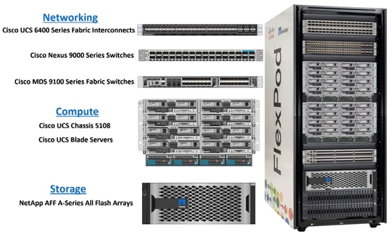
FlexPod datacenter architecture includes three components:
● Cisco Unified Computing System (UCS)
● Cisco MDS and Nexus Switches
● NetApp AFF Storage Systems
A benefit of the FlexPod architecture is the ability to customize or "flex" the environment to suit a customer's requirements. A FlexPod can easily be scaled as requirements and demand change. The unit can be scaled both up (adding resources to a FlexPod unit) and out (adding more FlexPod units). This document highlights the resiliency, cost benefit, and ease of deployment of a Fibre Channel storage solution to deploy Oracle RAC Database environments on FlexPod Infrastructure.
This solution provides an end-to-end architecture with Cisco Unified Computing System (UCS), Oracle, and NetApp technologies to demonstrates the benefits for running Oracle Multitenant RAC Databases 19c environment with excellent performance, scalability and high availability using FC and NVMe/FC.
The reference architecture covered in this document is built on the NetApp All Flash AFF A800 for Storage, Cisco B200 M5 Blade Servers for Compute, Cisco Nexus 9336C-FX2 Switches, Cisco MDS 9132T Fibre Channel Switches and Cisco Fabric Interconnects 6454 Fabric Interconnects for System Management in a single package. The design is flexible enough that the networking, computing, and storage can fit in one data center rack or be deployed according to a customer's data center design. The reference architecture reinforces the "wire-once" strategy, because as additional storage is added to the architecture, no re-cabling is required from the hosts to the Cisco UCS fabric interconnect.
The processing capabilities of CPUs have increased much faster than the processing demands of most database workloads. Sometimes databases are limited by CPU work, but it is generally a result of the processing limits of a single core and is not a limitation of the CPU. The result is an increasing number of idle cores on database servers that still must be licensed for the Oracle Database software. This underutilization of CPU resources is a waste of capital expenditure, not only in terms of licensing costs, but also in terms of the cost of the server itself, heat output, and so on. The Cisco UCS servers comes with different CPU options in terms of higher clock-speed which would help the database workloads and customer will have the option of using Higher clock-speed CPU with lower cores to keep the Oracle licensing costs down.
This solution consists of the following set of hardware combined into a single stack:
● Compute: Cisco UCS B200 M5 Blade Servers with Cisco Virtual Interface Cards (VICs) 1440
● Network: Cisco Nexus 9336C-FX2, Cisco MDS 9132T Fibre Channel and Cisco UCS Fabric Interconnect 6454 for network and management connectivity
● Storage: NetApp AFF A800 Storage
In this solution design, we have deployed two Cisco UCS 5108 Blade Server Chassis with 8 identical Intel Xeon CPU based Cisco UCS B200 M5 Blade Servers for hosting the 8-Node Oracle RAC Databases. The Cisco UCS B200 M5 Server has Virtual Interface Card (VIC) 1440 with port expander and they were connected to eight ports from each Cisco Fabric extender 2408 of the Cisco UCS Chassis to the Cisco Fabric Interconnects, which were in turn connected to the Cisco MDS Switches for upstream SAN connectivity to access the NetApp AFF storage.
Figure 2 shows the architecture diagram of the FlexPod components to deploy an eight node Oracle RAC 19c Database solution. This reference design is a typical network configuration that can be deployed in a customer's environments. The best practices and setup recommendations are described later in this document.
Figure 2. FlexPod Architecture Design
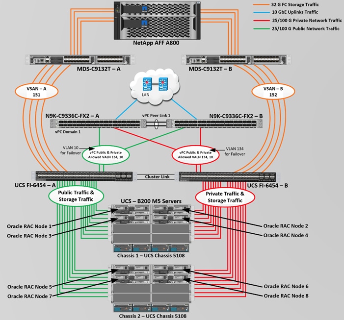
As shown in Figure 2, a pair of Cisco UCS 6454 Fabric Interconnects (FI) carries both storage and network traffic from the Cisco UCS B200 M5 server with the help of Cisco Nexus 9336C-FX2 and Cisco MDS 9132T switches. Both the Fabric Interconnects and the Cisco Nexus switches are clustered with the peer link between them to provide high availability.
As illustrated in Figure 2, 16 (8 x 25G link per chassis) links from the blade server chassis go to Fabric Interconnect – A. Similarly, 16 (8 x 25G link per chassis) links from the blade server chassis go to Fabric Interconnect – B. Fabric Interconnect – A links are used for Oracle Public Network Traffic (VLAN-134) shown as green lines while Fabric Interconnect – B links are used for Oracle Private Interconnect Traffic (VLAN 10) shown as red lines. Two virtual Port-Channels (vPCs) are configured to provide public network and private network traffic paths for the server blades to northbound nexus switches.
FC and NVMe/FC Storage access from both Fabric Interconnects to MDS Switches and NetApp Storage Array are shown as orange lines. Four 32Gb links are connected from FI – A to MDS – A Switch. Similarly, four 32Gb links are connected from FI – B to MDS – B Switch. The NetApp Storage AFF A800 have eight active FC connection goes to the Cisco MDS Switches. Four FC ports are connected to MDS-A, and other four FC ports are connected to MDS-B Switch. The NetApp Controller CT1 and Controller CT2 SAN ports 2a and 2b are connected to MDS – A Switch while the Controller CT1 and Controller CT2 SAN ports 2c and 2d are connected to MDS – B Switch. Also, two FC Port-Channels (PC) are configured to provide storage network paths from the server blades to storage array. Each PC has VSANs created for application and storage network data access.
![]() For Oracle RAC configuration on Cisco Unified Computing System, we recommend keeping all private interconnects network traffic local on a single Fabric interconnect. In such a case, the private traffic will stay local to that fabric interconnect and will not be routed via northbound network switch. In that way, all the inter server blade (or RAC node private) communications will be resolved locally at the fabric interconnects and this significantly reduces latency for Oracle Cache Fusion traffic.
For Oracle RAC configuration on Cisco Unified Computing System, we recommend keeping all private interconnects network traffic local on a single Fabric interconnect. In such a case, the private traffic will stay local to that fabric interconnect and will not be routed via northbound network switch. In that way, all the inter server blade (or RAC node private) communications will be resolved locally at the fabric interconnects and this significantly reduces latency for Oracle Cache Fusion traffic.
Additional 1Gb management connections will be needed for an out-of-band network switch that sits apart from this FlexPod infrastructure. Each UCS FI, MDS and Nexus switch is connected to the out-of-band network switch, and each AFF controller also has two connections to the out-of-band network switch.
Although this is the base design, each of the components can be scaled easily to support specific business requirements. For example, more servers or even blade chassis can be deployed to increase compute capacity, additional disk shelves can be deployed to improve I/O capability and throughput, and special hardware or software features can be added to introduce new features. This document guides you through the detailed steps for deploying the base architecture, as shown in the above figure. These procedures cover everything from physical cabling to network, compute, and storage device configurations.
This section describes the hardware and software components used to deploy an eight node Oracle RAC 19c Databases Solution on this architecture.
The inventory of the components used in this solution architecture is as per the table below.
Table 1. Hardware Inventory and Bill of Material
| Name |
Model/Product ID |
Description |
Quantity |
| Cisco UCS Blade Server Chassis |
UCSB-5108-AC2 |
Cisco UCS AC Blade Server Chassis, 6U with Eight Blade Server Slots |
2 |
| Cisco UCS Fabric Extender |
UCS-IOM-2408 |
Cisco UCS 2408 8x25 Gb Port IO Module |
4 |
| Cisco UCS B200 M5 Blade Server |
UCSB-B200-M5 |
Cisco UCS B200 M5 2 Socket Blade Server |
8 |
| Cisco UCS VIC 1440 |
UCSB-MLOM-40G-04 |
Cisco UCS VIC 1440 Blade MLOM |
8 |
| Cisco UCS Port Expander Card |
UCSB-MLOM-PT-01 |
Port Expander Card for Cisco UCS MLOM |
8 |
| Cisco UCS 6454 Fabric Interconnect |
UCS-FI-6454 |
Cisco UCS 6454 Fabric Interconnect |
2 |
| Cisco Nexus Switch |
N9K-9336C-FX2 |
Cisco Nexus 9336C-FX2 Switch |
2 |
| Cisco MDS Switch |
DS-C9132T-8PMESK9 |
Cisco MDS 9132T 32-Gbps 32-Port Fibre Channel Switch |
2 |
| NetApp AFF Storage |
AFF A800 |
NetApp AFF A-Series All Flash Arrays |
1 |
In this solution design, we used 8 identical Cisco UCS B200 M5 Blade Servers for hosting an 8 Node Oracle RAC Databases. The Cisco UCS B200 M5 Server configuration is listed in Table 2.
Table 2. Cisco UCS B200 M5 Blade Server
| Cisco UCS B200 M5 Server Configuration |
||
| Processor |
2 x Intel(R) Xeon(R) Gold 6248 2.50 GHz 150W 20C 27.50MB Cache DDR4 2933MHz 1TB |
UCS-CPU-I6248 |
| Memory |
8 x Samsung 64GB DDR4-2933-MHz LRDIMM/4Rx4/1.2v |
UCS-ML-X64G4RT-H |
| Cisco UCS VIC 1440 |
Cisco UCS VIC 1440 Blade MLOM |
UCSB-MLOM-40G-04 |
| Cisco UCS Port Expander Card |
Port Expander Card for Cisco UCS MLOM |
UCSB-MLOM-PT-01 |
| Processor |
2 x Intel(R) Xeon(R) Gold 6248 2.50 GHz 150W 20C 27.50MB Cache DDR4 2933MHz 1TB |
UCS-CPU-I6248 |
In this solution, we configured two vNIC and 4 vHBA on each host to carry all the network and storage traffic.
Table 3. vNIC and vHBA Configured on Each Linux Host
| vNIC Details |
|
| vNIC (eth0) |
Management and Public Network Traffic Interface for Oracle RAC. MTU = 1500 |
| vNIC (eth1) |
Private Server-to-Server Network (Cache Fusion) Traffic Interface for Oracle RAC. MTU = 9000 |
| vHBA0 |
FC Network Traffic & Boot from SAN through MDS-A Switch |
| vHBA1 |
FC Network Traffic & Boot from SAN through MDS-B Switch |
| vHBA2 |
NVMe/FC Network Traffic (Oracle RAC Storage Traffic) through MDS-A Switch |
| vHBA3 |
NVMe/FC Network Traffic (Oracle RAC Storage Traffic) through MDS-B Switch |
For this solution, we configured 2 VLANs to carry public and private network traffic as well as two VSANs to carry FC and NVMe/FC storage traffic as listed in Table 4.
Table 4. VLAN and VSAN Configurations
| VLAN and VSAN Configuration |
||
| VLAN |
||
| Name |
ID |
Description |
| Default VLAN |
1 |
Native VLAN |
| Public VLAN |
134 |
VLAN for Public Network Traffic |
| Private VLAN |
10 |
VLAN for Private Network Traffic |
| VSAN |
||
| Name |
ID |
Description |
| VSAN-A |
151 |
FC and NVMe/FC Network Traffic through for Fabric Interconnect A |
| VSAN-B |
152 |
FC and NVMe/FC Network Traffic through for Fabric Interconnect B |
This FlexPod solution consist of NetApp All Flash AFF Series Storage as described in Table 5.
Table 5. NetApp AFF A800 Storage Configuration
| Storage Components |
Description |
| AFF Flash Array |
NetApp All Flash AFF A800 Storage Array (24 x 1.75 TB NVMe SSD Drives) |
| Capacity |
41.82 TB |
| Connectivity |
8 x 32 Gb/s redundant FC, NVMe/FC 1 Gb/s redundant Ethernet (Management port) |
| Physical |
4 Rack Units |
For this FlexPod solution, we used the following versions of the software and firmware releases (Table 6).
Table 6. Software and Firmware Revisions
| Software and Firmware |
Version |
| Cisco UCS Manager System |
4.1(3b) |
| Cisco UCS Adapter VIC 1440 |
Package Version – 4.1 (3b) Running Version – 5.1 (3a) |
| Cisco eNIC (Cisco VIC Ethernet NIC Driver) (modinfo enic) |
4.0.0.14-802.74 (kmod-enic-4.0.0.14-802.74.rhel8u2.x86_64.rpm) |
| Cisco fNIC (Cisco VIC FC HBA Driver) (modinfo fnic) |
2.0.0.69-178.0 (kmod-fnic-2.0.0.69-178.0.rhel8u2.x86_64.rpm) |
| Oracle Linux |
Oracle Linux Release 8 Update 2 for x86 (64 bit) |
| Linux Kernel |
Linux 4.18.0-193.el8.x86_64 |
| Oracle Database 19c Grid Infrastructure for Linux x86-64 |
19.10.0.0.0 |
| Oracle Database 19c Enterprise Edition for Linux x86-64 |
19.10.0.0.0 |
| Cisco Nexus 9336C-FX2 NXOS |
9.3(3) |
| Cisco MDS 9132T System |
8.4(1) |
| NetApp Storage AFF A800 |
ONTAP 9.7P7 |
| FIO |
fio-3.7-3.el8.x86_64 |
| Oracle Swingbench |
2.5.971 |
| SLOB |
2.5.2.4 |
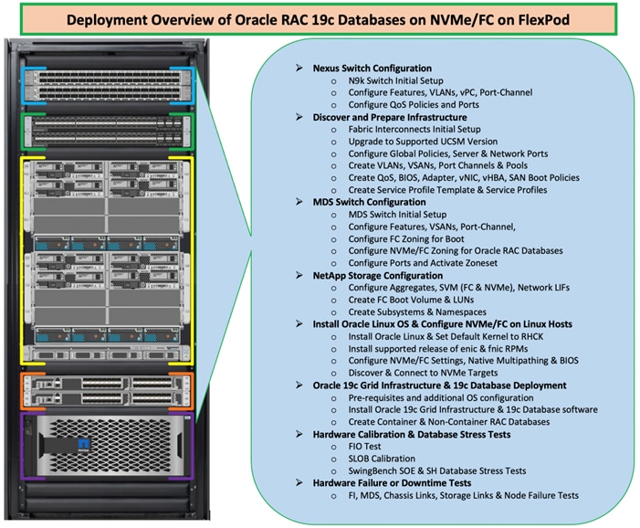
Figure 3 shows the high-level overview and steps for configuring various components to deploy and test the Oracle RAC Database 19c on FlexPod reference architecture.
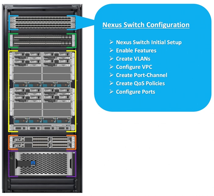
Cisco Nexus Switch Configuration
This section details the high-level steps to configure Cisco Nexus Switches as shown in Figure 4.
Figure 4. Cisco Nexus Switch Configuration
The following procedures describe how to configure the Cisco Nexus switches for use in a base FlexPod environment. This procedure assumes you’re using Cisco Nexus 9336C-FX2 switches deployed with the 100Gb end-to-end topology.
![]() On initial boot and connection to the serial or console port of the switch, the NX-OS setup should automatically start and attempt to enter Power on Auto Provisioning.
On initial boot and connection to the serial or console port of the switch, the NX-OS setup should automatically start and attempt to enter Power on Auto Provisioning.
To set up the initial configuration for the Cisco Nexus A switch on <nexus-A-hostname>, follow these steps:
Abort Power on Auto Provisioning and continue with normal setup? (yes/no) [n]: yes
Do you want to enforce secure password standard (yes/no) [y]: Enter
Enter the password for admin: <password>
Confirm the password for admin: <password>
Would you like to enter the basic configuration dialog (yes/no): yes
Create another login account (yes/no) [n]: Enter
Configure read-only SNMP community string (yes/no) [n]: Enter
Configure read-write SNMP community string (yes/no) [n]: Enter
Enter the switch name: <nexus-A-hostname>
Continue with Out-of-band (mgmt0) management configuration? (yes/no) [y]: Enter
Mgmt0 IPv4 address: <nexus-A-mgmt0-ip>
Mgmt0 IPv4 netmask: <nexus-A-mgmt0-netmask>
Configure the default gateway? (yes/no) [y]: Enter
IPv4 address of the default gateway: <nexus-A-mgmt0-gw>
Configure advanced IP options? (yes/no) [n]: Enter
Enable the telnet service? (yes/no) [n]: Enter
Enable the ssh service? (yes/no) [y]: Enter
Type of ssh key you would like to generate (dsa/rsa) [rsa]: Enter
Number of rsa key bits <1024-2048> [1024]: Enter
Configure the ntp server? (yes/no) [n]: y
NTP server IPv4 address: <global-ntp-server-ip>
Configure default interface layer (L3/L2) [L3]: L2
Configure default switchport interface state (shut/noshut) [noshut]: Enter
Configure CoPP system profile (strict/moderate/lenient/dense/skip) [strict]: Enter
Would you like to edit the configuration? (yes/no) [n]: Enter
Cisco Nexus B Switch
Similarly, follow the steps from section Cisco Nexus B Switch to setup the initial configuration for the Cisco Nexus B Switch and change the relevant switch hostname and management IP address.
To set global configuration, follow these steps on both the nexus switches:
1. Login as admin user into the Nexus Switch A and run the following commands to set global configurations on Switch A:
configure terminal
feature interface-vlan
feature hsrp
feature lacp
feature vpc
feature udld
spanning-tree port type network default
spanning-tree port type edge bpduguard default
port-channel load-balance src-dst l4port
policy-map type network-qos jumbo
class type network-qos class-default
mtu 9216
system qos
service-policy type network-qos jumbo
vrf context management
ip route 0.0.0.0/0 10.29.135.1
copy run start
2. Login as admin user into the Nexus Switch B and run the same above commands to set global configurations on Nexus Switch B.
![]() Make sure to run copy run start to save the configuration on each switch after the configuration is completed.
Make sure to run copy run start to save the configuration on each switch after the configuration is completed.
To create the necessary virtual local area networks (VLANs), follow these steps on both Nexus switches.
1. Login as admin user into the Nexus Switch A.
2. Create VLAN 134 for Public Network Traffic and VLAN 10 for Private Network Traffic:
configure terminal
vlan 134
name Oracle_RAC_Public_Network
no shutdown
vlan 10
name Oracle_RAC_Private_Network
no shutdown
interface Ethernet1/31
description connect to uplink switch
switchport access vlan 134
speed 1000
copy run start
3. Login as admin user into the Nexus Switch B and create VLAN 134 for Oracle RAC Public Network Traffic and VLAN 10 for Oracle RAC Private Network Traffic.
![]() Make sure to run copy run start to save the configuration on each switch after the configuration is completed.
Make sure to run copy run start to save the configuration on each switch after the configuration is completed.
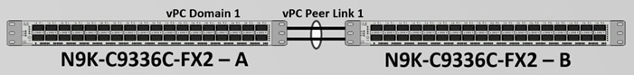
Virtual Port Channel (vPC) Summary for Network Traffic
A port channel bundles individual links into a channel group to create a single logical link that provides the aggregate bandwidth of up to eight physical links. If a member port within a port channel fails, traffic previously carried over the failed link switches to the remaining member ports within the port channel. Port channeling also load balances traffic across these physical interfaces. The port channel stays operational as long as at least one physical interface within the port channel is operational. Using port channels, Cisco NX-OS provides wider bandwidth, redundancy, and load balancing across the channels
In the Cisco Nexus Switch topology, a single vPC feature is enabled to provide HA, faster convergence in the event of a failure, and greater throughput. Cisco Nexus vPC configurations with the vPC domains and corresponding vPC names and IDs for Oracle Database Servers is shown in Table 7.
| vPC Domain |
vPC Name |
vPC ID |
| 1 |
Peer-Link |
1 |
| 1 |
vPC FI-A |
51 |
| 1 |
vPC FI-B |
52 |
As listed in Table 7, a single vPC domain with Domain ID 1 is created across two Nexus switches to define vPC members to carry specific VLAN network traffic. In this topology, we defined a total number of 3 vPCs.
vPC ID 1 is defined as Peer link communication between the two Nexus switches. vPC IDs 51 and 52 are configured for both Cisco UCS fabric interconnects. Please follow these steps to create this configuration.
![]() A port channel bundles up to eight individual interfaces into a group to provide increased bandwidth and redundancy.
A port channel bundles up to eight individual interfaces into a group to provide increased bandwidth and redundancy.
For vPC 1 as Peer-link, we used interfaces 1 and 2 for Peer-Link. You may choose an appropriate number of ports based on your needs. To create the necessary port channels between devices, follow these steps on both the Nexus Switches:
4. Login as admin user into the Nexus Switch A:
configure terminal
vpc domain 1
peer-keepalive destination 10.29.134.53 source 10.29.134.52
auto-recovery
interface port-channel 1
description vPC peer-link
switchport mode trunk
switchport trunk allowed vlan 1,10,134
spanning-tree port type network
vpc peer-link
interface Ethernet1/1
description Peer link 100g connected to N9K-B-Eth1/1
switchport mode trunk
switchport trunk allowed vlan 1,10,134
channel-group 1 mode active
interface Ethernet1/2
description Peer link 100g connected to N9K-B-Eth1/2
switchport mode trunk
switchport trunk allowed vlan 1,10,134
channel-group 1 mode active
exit
copy run start
5. Login as admin user into the Nexus Switch B and repeat the above steps to configure second nexus switch. Make sure to changes the description of interfaces and peer-keepalive destination and source IP addresses.
Create vPC Configuration between Nexus Switches and Fabric Interconnects
This section describes how to create and configure port channel 51 and 52 for network traffic between the Nexus and Fabric Interconnect Switches.
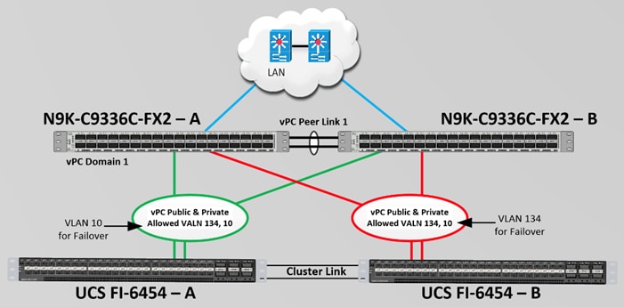
Table 8 lists the vPC IDs, allowed VLAN IDs, and Ethernet uplink ports.
| vPC Description |
vPC ID |
Fabric Interconnects Ports |
Nexus Switch Ports |
Allowed VLANs |
| Port Channel FI-A |
51 |
FI-A Port 1/49 |
N9K-A Port 1/25 |
134, 10 Note: VLAN 10 Needed for Failover |
| FI-A Port 1/50 |
N9K-B Port 1/25 |
|||
| Port Channel FI-B |
52 |
FI-B Port 1/49 |
N9K-A Port 1/26 |
10, 134 Note: VLAN 134 Needed for Failover |
| FI-B Port 1/50 |
N9K-B Port 1/26 |
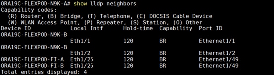
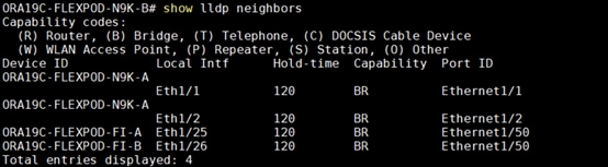
Verify the ports connectivity on both the nexus switches as shown below:
To configure port channels on Nexus Switches, follow these steps:
6. Login as admin user into the Nexus Switch A and perform the following steps:
configure terminal
interface port-channel51
description Port-Channel FI-A
switchport mode trunk
switchport trunk allowed vlan 1,10,134
spanning-tree port type edge trunk
mtu 9216
vpc 51
no shutdown
interface port-channel52
description Port-Channel FI-B
switchport mode trunk
switchport trunk allowed vlan 1,10,134
spanning-tree port type edge trunk
mtu 9216
vpc 52
no shutdown
interface Ethernet1/25
description 100g link to Fabric-Interconnect A port 49
switchport mode trunk
switchport trunk allowed vlan 1,10,134
spanning-tree port type edge trunk
mtu 9216
channel-group 51 mode active
no shutdown
interface Ethernet1/26
description 100g link to Fabric-Interconnect B Port 49
switchport mode trunk
switchport trunk allowed vlan 1,10,134
spanning-tree port type edge trunk
mtu 9216
channel-group 52 mode active
no shutdown
copy run start
7. Login as admin user into the Nexus Switch B and run the following commands to configure the second Nexus switch:
configure terminal
interface port-channel51
description Port-Channel FI-A
switchport mode trunk
switchport trunk allowed vlan 1,10,134
spanning-tree port type edge trunk
mtu 9216
vpc 51
no shutdown
interface port-channel52
description Port-Channel FI-B
switchport mode trunk
switchport trunk allowed vlan 1,10,134
spanning-tree port type edge trunk
mtu 9216
vpc 52
no shutdown
interface Ethernet1/25
description 100g link to Fabric-Interconnect A port 50
switchport mode trunk
switchport trunk allowed vlan 1,10,134
spanning-tree port type edge trunk
mtu 9216
channel-group 51 mode active
no shutdown
interface Ethernet1/26
description 100g link to Fabric-Interconnect B Port 50
switchport mode trunk
switchport trunk allowed vlan 1,10,134
spanning-tree port type edge trunk
mtu 9216
channel-group 52 mode active
no shutdown
copy run start
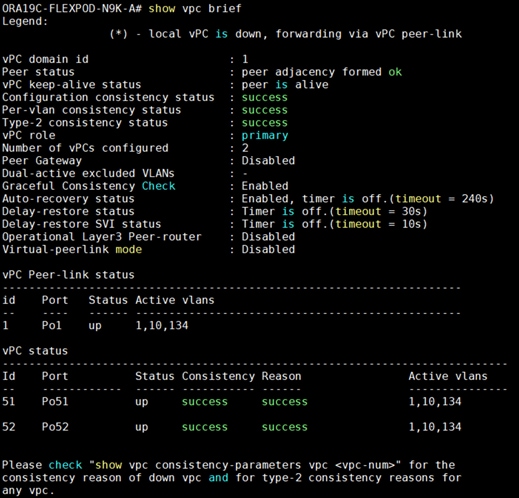
To verify all the port-channel status, run the following commands into the Nexus Switches:
1. Nexus Switch A Port-Channel Summary:

2. Nexus Switch B Port-Channel Summary:

3. Nexus Switch A vPC Status:
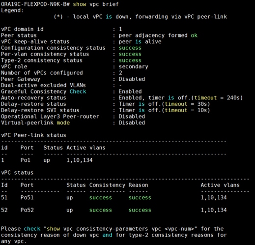
4. Nexus Switch B vPC Status:
This section details the Cisco UCS configuration that was done as part of the infrastructure buildout. The racking, power, and installation of the chassis are described in the installation guide (see https://www.cisco.com/c/en/us/support/servers-unified-computing/ucs-manager/products-installation-guides-list.html).
![]() It is beyond the scope of this document to explain the Cisco UCS infrastructure setup and connectivity. The documentation guides and examples are available here: https://www.cisco.com/c/en/us/support/servers-unified-computing/ucs-manager/products-installation-and-configuration-guides-list.html
It is beyond the scope of this document to explain the Cisco UCS infrastructure setup and connectivity. The documentation guides and examples are available here: https://www.cisco.com/c/en/us/support/servers-unified-computing/ucs-manager/products-installation-and-configuration-guides-list.html
Using logical servers that are disassociated from the physical hardware removes many limiting constraints around how servers are provisioned. Cisco UCS Service Profiles contain values for a server's property settings, including virtual network interface cards (vNICs), MAC addresses, boot policies, firmware policies, fabric connectivity, external management, and HA information. The service profiles represent all the attributes of a logical server in Cisco UCS model. By abstracting these settings from the physical server into a Cisco Service Profile, the Service Profile can then be deployed to any physical compute hardware within the Cisco UCS domain. Furthermore, Service Profiles can, at any time, be migrated from one physical server to another. Furthermore, Cisco is the only hardware provider to offer a truly unified management platform, with Cisco UCS Service Profiles and hardware abstraction capabilities extending to both blade and rack servers.
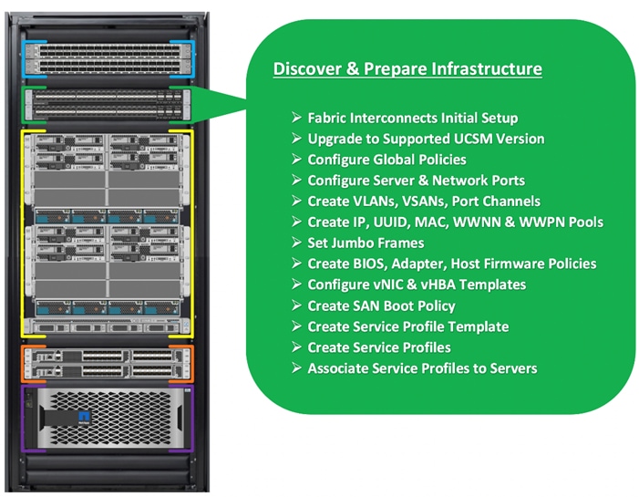
High-Level Steps to Configure Base Cisco UCS
The following are the high-level steps involved for a Cisco UCS configuration:
1. Perform Initial Setup of Fabric Interconnects for a Cluster Setup
2. Upgrade UCS Manager Software to Version 4.1(3b)
3. Synchronize Cisco UCS to NTP
4. Configure Fabric Interconnects for Chassis and Blade Discovery
5. Configure Global Policies
6. Configure Server Ports
7. Configure LAN and SAN
8. Configure Ethernet LAN Uplink Ports
9. Create Uplink Port Channels to Nexus Switches
10. Configure FC SAN Uplink Ports
11. Configure VLANs
12. Configure VSANs
13. Create FC Uplink Port Channels to MDS Switches
14. Enable FC Uplink VSAN Trunking (FCP)
15. Configure IP, UUID, Server, MAC, WWNN and WWPN Pools
16. IP Pool Creation
17. UUID Suffix Pool Creation
18. Server Pool Creation
19. MAC Pool Creation
20. WWNN and WWPN Pool
21. Set Jumbo Frames in both the Fabric Interconnect
22. Configure Server BIOS Policy
23. Create Adapter Policy
24. Create Adapter Policy for Public and Private Network Interfaces
25. Create Adapter Policy for NVMe FC Storage Network Interfaces
26. Configure Update Default Maintenance Policy
27. Configure Host Firmware Policy
28. Configure vNIC and vHBA Template
29. Create Public vNIC Template
30. Create Private vNIC Template
31. Create Storage FC Storage vHBA Template
32. Create Server Boot Policy for SAN Boot
The details for each of these steps are documented in the following sections.
Perform Initial Setup of Cisco UCS 6454 Fabric Interconnects for a Cluster Setup
This section provides detailed procedures for configuring the Cisco Unified Computing System (Cisco UCS) for use in a FlexPod environment. The steps are necessary to provision the Cisco UCS B-Series and C-Series servers and should be followed precisely to avoid improper configuration.
Configure FI-A and FI-B
To configure the UCS Fabric Interconnects, follow these steps.
1. Verify the following physical connections on the fabric interconnect:
a. The management Ethernet port (mgmt0) is connected to an external hub, switch, or router
b. The L1 ports on both fabric interconnects are directly connected to each other
c. The L2 ports on both fabric interconnects are directly connected to each other
2. Connect to the console port on the first Fabric Interconnect and follow these steps:
Enter the configuration method. (console/gui) ? console
Enter the setup mode; setup newly or restore from backup. (setup/restore) ? setup
You have chosen to setup a new Fabric interconnect. Continue? (y/n): y
Enforce strong password? (y/n) [y]: Enter
Enter the password for admin: <password>
Confirm the password for admin: <password>
Is this Fabric interconnect part of a cluster(select 'no' for standalone)? (yes/no) [n]: y
Enter the switch fabric (A/B) []: A
Enter the system name: <ucs-cluster-name>
Physical Switch Mgmt0 IP address : <ucsa-mgmt-ip>
Physical Switch Mgmt0 IPv4 netmask : <ucsa-mgmt-mask>
IPv4 address of the default gateway : <ucsa-mgmt-gateway>
Cluster IPv4 address : <ucs-cluster-ip>
Configure the DNS Server IP address? (yes/no) [n]: y
DNS IP address : <dns-server-1-ip>
Configure the default domain name? (yes/no) [n]: y
Default domain name : <ad-dns-domain-name>
Join centralized management environment (UCS Central)? (yes/no) [n]: Enter
Apply and save the configuration (select 'no' if you want to re-enter)? (yes/no): yes
3. Review the settings printed to the console. Answer yes to apply and save the configuration.
4. Wait for the login prompt to make the configuration has been saved to Fabric Interconnect A.
5. Connect console port on the second Fabric Interconnect B and follow these steps:
Enter the configuration method. (console/gui) ? console
Installer has detected the presence of a peer Fabric interconnect. This Fabric interconnect will be added to the cluster. Continue (y/n) ? y
Enter the admin password of the peer Fabric interconnect: <password>
Connecting to peer Fabric interconnect... done
Retrieving config from peer Fabric interconnect... done
Peer Fabric interconnect Mgmt0 IPv4 Address: <ucsa-mgmt-ip>
Peer Fabric interconnect Mgmt0 IPv4 Netmask: <ucsa-mgmt-mask>
Cluster IPv4 address : <ucs-cluster-ip>
Peer FI is IPv4 Cluster enabled. Please Provide Local Fabric Interconnect Mgmt0 IPv4 Address
Physical Switch Mgmt0 IP address : <ucsb-mgmt-ip>
Local fabric interconnect model(UCS-FI-6454)
Peer fabric interconnect is compatible with the local fabric interconnect. Continuing with the installer...
Apply and save the configuration (select 'no' if you want to re-enter)? (yes/no): yes
6. Review the settings printed to the console. Answer yes to apply and save the configuration.
7. Wait for the login prompt to make the configuration has been saved to Fabric Interconnect B.
To log into the Cisco Unified Computing System (UCS) environment, follow these steps:
1. Open a web browser and navigate to the Cisco UCS fabric interconnect cluster address.
2. Click the Launch UCS Manager link under HTML to launch Cisco UCS Manager.
3. If prompted to accept security certificates, accept as necessary.
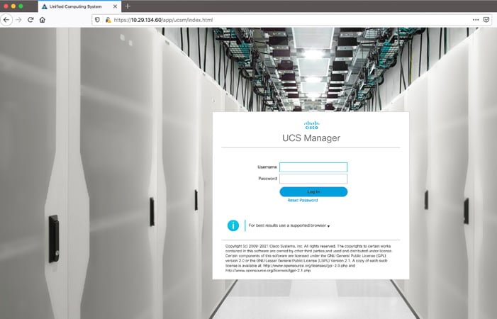
4. When prompted, enter admin as the username and enter the administrative password.
5. Click Login to log into Cisco UCS Manager.
It is highly recommended by Cisco to configure Call Home in Cisco UCS Manager. Configuring Call Home will accelerate resolution of support cases. To configure Call Home, follow these steps:
1. In Cisco UCS Manager, click Admin.
2. Select All > Communication Management > Call Home.
3. Change the State to On.
4. Fill in all the fields according to your Management preferences and click Save Changes and OK to complete configuring Call Home.
Upgrade Cisco UCS Manager Software to Version 4.1 (3b)
This solution was configured on Cisco UCS 4.1(3b) software release. To upgrade the Cisco UCS Manager software and the Cisco UCS Fabric Interconnect software to version 4.1, go to https://software.cisco.com/download/home/283612660/type/283655658/release/4.1(3b)
For more information about Install and Upgrade Guides, go to: https://www.cisco.com/c/en/us/support/servers-unified-computing/ucs-manager/products-installation-guides-list.html
To synchronize the Cisco UCS environment to the NTP server, follow these steps:
1. In Cisco UCS Manager, in the navigation pane, click the Admin tab.
2. Select All > Time zone Management.
3. In the Properties pane, select the appropriate time zone in the Time zone menu.
4. Click Save Changes and then click OK.
5. Click Add NTP Server.
6. Enter the NTP server IP address and click OK.
7. Click OK to finish.
Configure Fabric Interconnect for Chassis and Server Discovery
Cisco UCS 6454 Fabric Interconnects are configured for redundancy. It provides resiliency in case of failures. The first step to establish connectivity between blades and Fabric Interconnects.
Configure Global Policies
The chassis discovery policy determines how the system reacts when you add a new chassis. We recommend using the platform max value as shown. Using platform max helps ensure that Cisco UCS Manager uses the maximum number of IOM uplinks available.
To configure global policies, follow these steps:
1. Go to Equipment > Policies > Global Policies > Chassis/FEX Discovery Policies. As shown in the screenshot below, select Action as Platform Max from the drop-down list and set Link Grouping to Port Channel.
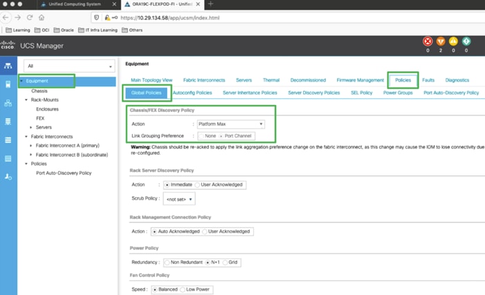
2. Click Save Changes.
3. Click OK.
Configure Server Ports
Configure Server Ports to initiate Chassis and Blade discovery. To configure server ports, follow these steps:
1. Go to Equipment > Fabric Interconnects > Fabric Interconnect A > Fixed Module > Ethernet Ports.
2. Select the ports (for this solution ports are 17-32) which are connected to the Cisco IO Modules of the two Cisco UCS B-Series 5108 Chassis.
3. Right-click and select Configure as Server Port.
4. Click Yes to confirm and click OK.
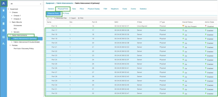
5. Repeat steps 1-4 for Fabric Interconnect B.
6. After configuring Server Ports, acknowledge both the Chassis. Go to Equipment > Chassis > Chassis 1 > General > Actions > select Acknowledge Chassis. Similarly, acknowledge the chassis 2.
7. After acknowledging both the chassis, Re-acknowledge all the servers placed in the chassis. Go to Equipment > Chassis 1 > Servers > Server 1 > General > Actions > select Server Maintenance > select option Re-acknowledge and click OK. Similarly, repeat the process to Re-acknowledge all the eight Servers.
8. Once the acknowledgement of the Servers completed, verify Port-channel of Internal LAN. Go to tab LAN > Internal LAN > Internal Fabric A > Port Channels as shown below.
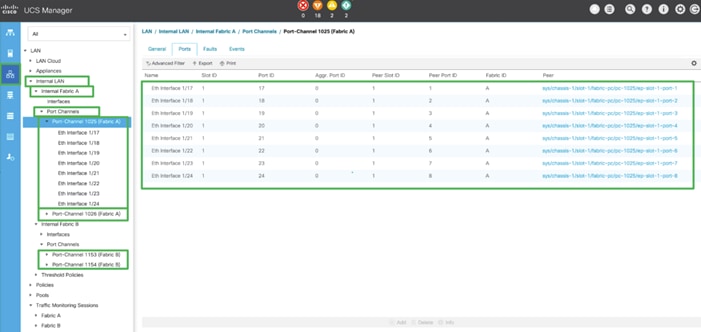
9. Verify the same for Internal Fabric B.
Configure LAN and SAN on Cisco UCS Manager
Configure Ethernet Uplink Ports and Fibre Channel (FC) Storage ports on Cisco UCS as explained below.
Configure Ethernet LAN Uplink Ports
To configure network ports used to uplink the Fabric Interconnects to the Nexus switches, follow these steps:
1. In Cisco UCS Manager, in the navigation pane, click the Equipment tab.
2. Select Equipment > Fabric Interconnects > Fabric Interconnect A > Fixed Module.
3. Expand Ethernet Ports.
4. Select ports (for this solution ports are 49-50) that are connected to the Nexus switches, right-click them, and select Configure as Network Port.
5. Click Yes to confirm ports and click OK.
6. Verify the Ports connected to Nexus upstream switches are now configured as network ports.
7. Repeat steps 1-6 for Fabric Interconnect B. The screenshot shows the network uplink ports for Fabric A.
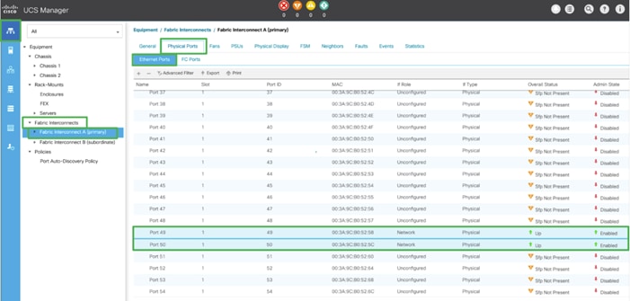
Now two uplink ports have been created on each Fabric Interconnect as shown above. These ports will be used to create Virtual Port Channel in the next section.
Create Uplink Port Channels to Cisco Nexus Switches
In this procedure, two port channels were created: one from Fabric A to both Nexus switch and one from Fabric B to both Nexus switch. To configure the necessary port channels in the Cisco UCS environment, follow these steps:
1. In Cisco UCS Manager, click the LAN tab in the navigation pane.
2. Under LAN > LAN Cloud, expand node Fabric A tree:
a. Right-click Port Channels.
b. Select Create Port Channel.
c. Enter 51 as the unique ID of the port channel.
d. Enter FI-A as the name of the port channel.
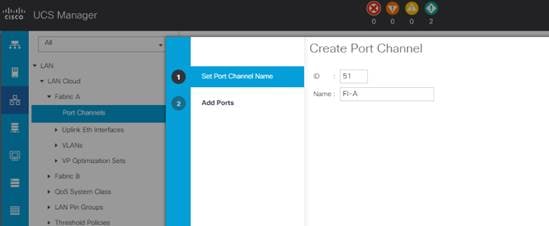
e. Click Next.
f. Select Ethernet ports 49-50 for the port channel.
g. Click >> to add the ports to the port channel
3. Click Finish to create the port channel and then click OK.
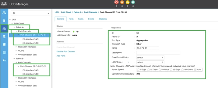
4. Repeat steps 1-3 for Fabric Interconnect B, substituting 52 for the port channel number and FI-B for the name.
Configure FC SAN Uplink Ports
To enable the Fibre channel ports, follow these steps for the FI 6454:
1. In Cisco UCS Manager, click Equipment.
2. Select Equipment > Fabric Interconnects > Fabric Interconnect A (primary).
3. Select Configure Unified Ports.
4. Click Yes on the pop-up window warning that changes to the fixed module will require a reboot of the fabric interconnect and changes to the expansion module will require a reboot of that module.
5. Within the Configured Fixed Ports pop-up window move the gray slider bar from the left to the right to select either 4, 8, or 12 ports to be set as FC Uplinks.
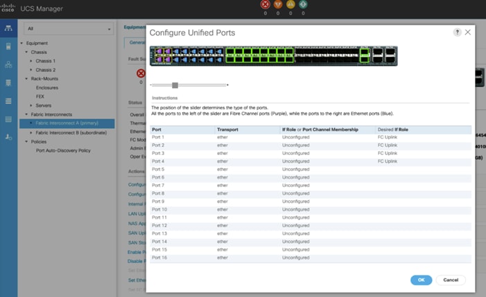
6. For this solution, we configured the first four ports on the FI as FC Uplink ports. Click OK, then click Yes, then click OK to continue
![]() Applying this configuration will cause the immediate reboot of Fabric Interconnect and/or Expansion Module(s).
Applying this configuration will cause the immediate reboot of Fabric Interconnect and/or Expansion Module(s).
7. Select Equipment > Fabric Interconnects > Fabric Interconnect B (primary).
8. Select Configure Unified Ports.
9. Click Yes on the pop-up window warning that changes to the fixed module will require a reboot of the fabric interconnect and changes to the expansion module will require a reboot of that module.
10. Within the Configured Fixed Ports pop-up window move the gray slider bar from the left to the right to select either 4, 8, or 12 ports to be set as FC Uplinks.
11. Click OK then click Yes then click OK to continue.
12. Wait for both Fabric Interconnects to reboot.
13. Log back into Cisco UCS Manager.
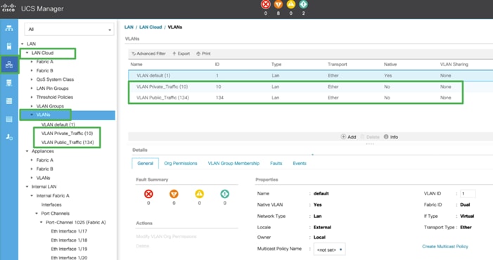
Configure VLAN
In this solution, two VLANs were created: one for private network (VLAN 10) traffic, one for public network (VLAN 134) traffic. These two VLANs will be used in the vNIC templates that are discussed later.
To configure the necessary virtual local area networks (VLANs) for the Cisco UCS environment, follow these steps:
![]() It is very important to create both VLANs as global across both fabric interconnects. This way, VLAN identity is maintained across the fabric interconnects in case of NIC failover.
It is very important to create both VLANs as global across both fabric interconnects. This way, VLAN identity is maintained across the fabric interconnects in case of NIC failover.
1. In Cisco UCS Manager, click the LAN tab in the navigation pane.
2. Select LAN > LAN Cloud.
3. Right-click VLANs.
4. Select Create VLANs.
5. Enter Public_Traffic as the name of the VLAN to be used for Public Network Traffic.
6. Keep the Common/Global option selected for the scope of the VLAN.
7. Enter 134 as the ID of the VLAN ID.
8. Keep the Sharing Type as None.
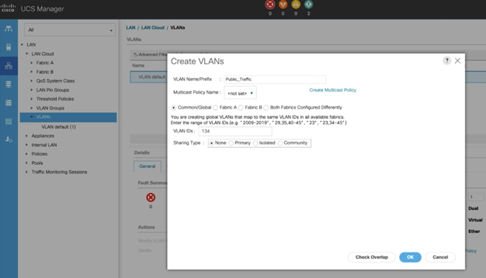
9. Click OK and then click OK again.
10. Create the second VLAN: for private network (VLAN 10) traffic and remaining two storage VLANs for storage network (VALN 11 and 12) traffic as shown below:
These two VLANs will be used in the vNIC templates that are described in this CVD.
Configure VSAN
In this solution, we created two VSANs. VSAN-A 151 and VSAN-B 152 for FC SAN Boot and NVMe/FC Storage Access.
To configure the necessary virtual storage area networks (VSANs) for the Cisco UCS environment, follow these steps:
1. In Cisco UCS Manager, click the SAN tab in the navigation pane.
2. Select SAN > SAN Cloud > Fabric A > VSANs
3. Under VSANs, right-click on VSANs.
4. Select Create VSAN.
5. Enter VSAN-A as the name of the VSAN.
6. Leave FC Zoning set at Disabled.
7. Select Fabric A for the scope of the VSAN.
8. Enter VSAN ID as 151.
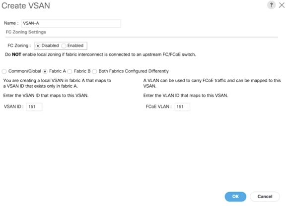
9. Click OK and then click OK again
10. Repeat steps 1-9 to create the VSAN 152 on FI-B.
![]() Enter a unique VSAN ID and a corresponding FCoE VLAN ID that matches the configuration in the MDS switch for Fabric A. It is recommended to use the same ID for both parameters and to use something other than 1.
Enter a unique VSAN ID and a corresponding FCoE VLAN ID that matches the configuration in the MDS switch for Fabric A. It is recommended to use the same ID for both parameters and to use something other than 1.
Create FC Uplink Port Channels to MDS Switches
In this solution, we created two FC Port Chanel. The first FC Port Channel is between FI-A to MDS-A and the second FC Port Channel is between FI-B to MDS-B.
To create FC Port channel, follow these steps on the FI 6454:
1. In Cisco UCS Manager, click the SAN tab.
2. Select SAN > SAN Cloud > Fabric A > FC Port Channels > and then right-click on the FC Port Channel.
3. Enter the name of Port Channel as FC-PC-A and unique ID as 251 and click Next
4. Select the appropriate ports of FI-A which are going to MDS-A and click the button >> to select those ports as a member of the Port Channel. For this solution, we configured all the four ports as a Port Channel ports as shown in the screenshot below:
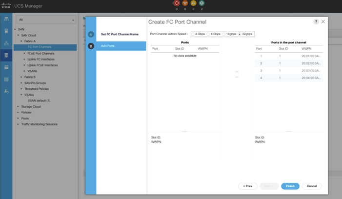
5. Click Finish to create this FC Port Channel for FI-A.
6. Repeat steps 1-5 to create the FC Port Channel on FI-B with related FC Ports going to MDS-B.
![]() We configured the FI-B Port Channel as FC-PC-B with unique ID 252 as shown below.
We configured the FI-B Port Channel as FC-PC-B with unique ID 252 as shown below.
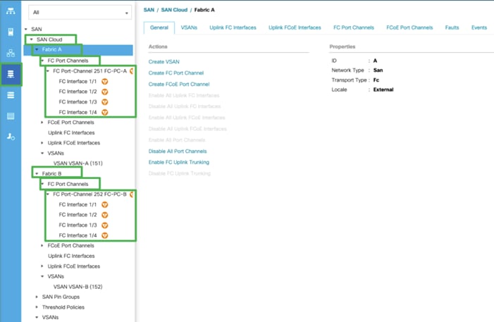
7. Select VSAN-A 151 for FC-PC-A and click Save Changes.
8. Similarly, select VSAN-B 152 for FC-PC-B and click Save Changes.
![]() The MDS Switch is configured in the following section and after the appropriate VSAN and FC ports configuration, the FC Ports and Port-Channel will become ACTIVE.
The MDS Switch is configured in the following section and after the appropriate VSAN and FC ports configuration, the FC Ports and Port-Channel will become ACTIVE.
Enable FC Uplink VSAN Trunking (FCP)
To enable VSAN trunking on the FC Uplinks in the Cisco UCS environment, follow these steps:
1. In Cisco UCS Manager, click SAN.
2. Expand SAN > SAN Cloud.
3. Choose Fabric A and in the Actions pane choose Enable FC Uplink Trunking.
4. Click Yes on the Confirmation and Warning and then click OK.
5. Choose Fabric B and in the Actions pane choose Enable FC Uplink Trunking.
6. Click Yes on the Confirmation and Warning. Click OK to finish.
![]() Enabling VSAN trunking is optional. It is important that the Cisco Nexus VSAN trunking configuration match the configuration set in Cisco UCS Manager.
Enabling VSAN trunking is optional. It is important that the Cisco Nexus VSAN trunking configuration match the configuration set in Cisco UCS Manager.
Configure IP, UUID, Server, MAC, WWNN and WWPN Pools
IP Pool Creation
An IP address pool on the out of band management network must be created to facilitate KVM access to each compute node in the UCS domain. To create a block of IP addresses for server KVM access in the Cisco UCS environment, follow these steps:
1. In Cisco UCS Manager, in the navigation pane, click the LAN tab.
2. Select Pools > root > IP Pools >click Create IP Pool.
3. We have named IP Pool as Ora19C-KVM Pool for this solution.
4. Select option Sequential to assign IP in sequential order then click Next.
5. Click Add IPv4 Block.
6. Enter the starting IP address of the block and the number of IP addresses required, and the subnet and gateway information as shown in the screenshot according to your environment.
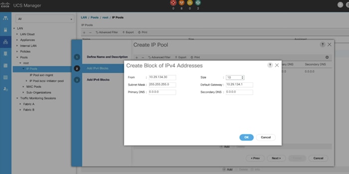
7. Click Next and then click Finish to create the IP block.
UUID Suffix Pool Creation
To configure the necessary universally unique identifier (UUID) suffix pool for the Cisco UCS environment, follow these steps:
1. In Cisco UCS Manager, click the Servers tab in the navigation pane.
2. Select Pools > root.
3. Right-click UUID Suffix Pools and then select Create UUID Suffix Pool.
4. Enter ORA19C-UUID as the name of the UUID Pool name.
5. Optional: Enter a description for the UUID pool.
6. Keep the prefix at the derived option and select Sequential in as Assignment Order then click Next.
7. Click Add to add a block of UUIDs.
8. Create a starting point UUID as per your environment.
9. Specify a size for the UUID block that is sufficient to support the available blade or server resources.
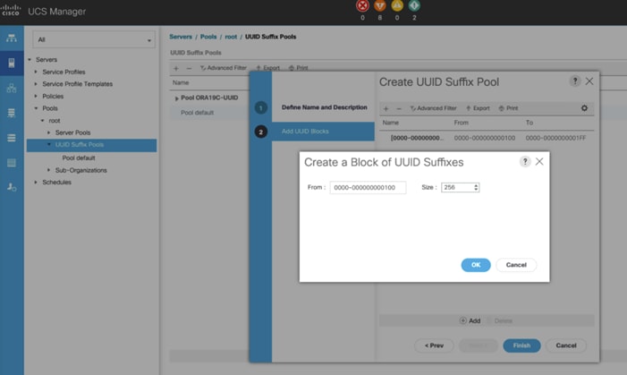
10. Clink OK then click Finish to complete the UUID Pool congiruration.
Server Pool Creation
To configure the necessary server pool for the Cisco UCS environment, follow these steps:
![]() Consider creating unique server pools to achieve the granularity that is required in your environment.
Consider creating unique server pools to achieve the granularity that is required in your environment.
1. In Cisco UCS Manager, click the Servers tab in the navigation pane.
2. Select Pools > root > Right-click Server Pools > Select Create Server Pool.
3. Enter ORA19C-SERVER-POOL as the name of the server pool.
4. Optional: Enter a description for the server pool then click Next.
5. Select all 8 servers to be used for the Oracle RAC management and click >> to add them to the server pool.
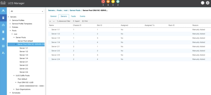
6. Click Finish and then click OK.
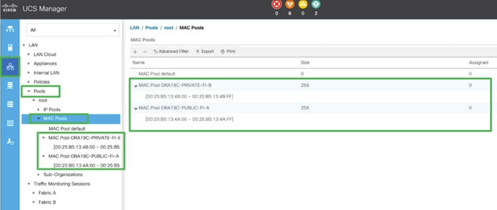
MAC Pool Creation
In this solution, we created two MAC Pool as ORA19C-PUBLIC-FI-A and ORA19C-PRIVATE-FI-B to provide MAC addresses for Public and Private Network Interfaces.
To configure the necessary MAC address pools for the Cisco UCS environment, follow these steps:
1. In Cisco UCS Manager, click the LAN tab in the navigation pane.
2. Select Pools > root > right-click MAC Pools under the root organization.
3. Select Create MAC Pool to create the MAC address pool.
4. Enter ORA19C-PUBLIC-FI-A as the name for MAC pool.
5. Enter the seed MAC address and provide the number of MAC addresses to be provisioned.
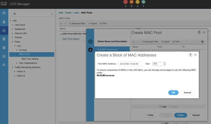
6. Click OK and then click Finish.
7. In the confirmation message, click OK.
8. Create MAC Pool B and assign unique MAC Addresses as shown below.
WWNN and WWPN Pool Creation
In this solution, we configured one WWNN Pool to provide SAN access point for Linux hosts. To configure the necessary WWNN pools for the Cisco UCS environment, follow these steps:
![]() These WWNN and WWPN entries will be used to access storage through SAN configuration
These WWNN and WWPN entries will be used to access storage through SAN configuration
1. In Cisco UCS Manager, click the SAN tab in the navigation pane.
2. Select Pools > Root > WWNN Pools > right-click WWNN Pools > Select Create WWNN Pool.
3. Assign name as ORA19C-WWNN-A and Assignment Order as sequential and click Next.
4. Click Add and create a WWN Block as shown below.
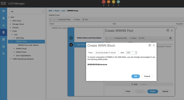
5. Click OK and then Finish.
In this solution, we created two WWPNs; ORA19C-WWPN-A and ORA19C-WWPN-B Pool, for the World Wide Port Name. To configure the necessary WWPN pools for the Cisco UCS environment, follow these steps:
1. In Cisco UCS Manager, click the SAN tab in the navigation pane.
2. Select Pools > Root > WWPN Pools > right-click WWPN Pools > select Create WWPN Pool.
3. Assign the name ORA19C-WWPN-A and Assignment Order as sequential.
4. Click Next and then click Add to add block of Ports.
5. Enter Block for WWN and size.
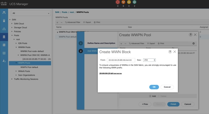
6. Click OK and then Finish.
7. Configure the ORA19C-WWPN-B Pool as well and assign the unique block IDs as shown below.
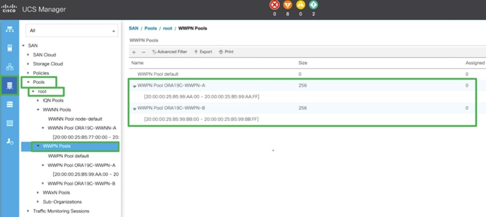
![]() When there are multiple UCS domains sitting in adjacency, it is important that these blocks; the WWNN, WWPN, and MAC, hold differing values between each set.
When there are multiple UCS domains sitting in adjacency, it is important that these blocks; the WWNN, WWPN, and MAC, hold differing values between each set.
Set Jumbo Frames in both the Cisco Fabric Interconnect
To configure jumbo frames and enable quality of service in the Cisco UCS fabric, follow these steps:
1. In Cisco UCS Manager, click the LAN tab in the navigation pane.
2. Select LAN > LAN Cloud > QoS System Class.
3. Click the General tab.
4. On the Best Effort row, enter 9216 in the box under the MTU column.
5. Click Save Changes in the bottom of the window.
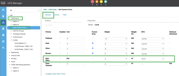
6. Click OK.
![]() The only the Fibre Channel and Best Effort QoS System Classes are enabled in this FlexPod implementation. The Cisco UCS and Nexus switches are intentionally configured this way so that all IP traffic within the FlexPod will be treated as Best Effort.
The only the Fibre Channel and Best Effort QoS System Classes are enabled in this FlexPod implementation. The Cisco UCS and Nexus switches are intentionally configured this way so that all IP traffic within the FlexPod will be treated as Best Effort.
![]() Enabling the other QoS System Classes without having a comprehensive, end-to-end QoS setup in place can cause difficult to troubleshoot issues.
Enabling the other QoS System Classes without having a comprehensive, end-to-end QoS setup in place can cause difficult to troubleshoot issues.
![]() All of the Server BIOS policies may have to be required on your setup. Please follow the steps according to your environment and requirement. The following changes were made on the test bed where Oracle RAC installed. Please validate and change as needed.
All of the Server BIOS policies may have to be required on your setup. Please follow the steps according to your environment and requirement. The following changes were made on the test bed where Oracle RAC installed. Please validate and change as needed.
![]() For more detailed on BIOS Settings, go to https://www.cisco.com/c/en/us/products/collateral/servers-unified-computing/ucs-b-series-blade-servers/white-paper-c11-744678.html
For more detailed on BIOS Settings, go to https://www.cisco.com/c/en/us/products/collateral/servers-unified-computing/ucs-b-series-blade-servers/white-paper-c11-744678.html
![]() It is recommended to disable C states in the BIOS and in addition, Oracle recommends disabling it from OS level as well by modifying grub entries. We will cover the OS level settings in the Operating system configuration section.
It is recommended to disable C states in the BIOS and in addition, Oracle recommends disabling it from OS level as well by modifying grub entries. We will cover the OS level settings in the Operating system configuration section.
To create a server BIOS policy for the Cisco UCS environment, follow these steps:
1. In Cisco UCS Manager, click Servers.
2. Select Policies > root.
3. Right-click BIOS Policies.
4. Select Create BIOS Policy.
5. Enter ORA19C_BIOS as the BIOS policy name
6. Select and click the newly created BIOS Policy.
7. Click the Advanced tab, leaving the Processor tab selected within the Advanced tab.
8. Set the following within the Processor tab:
a. CPU Hardware Power Management: HWPM Native Mode
b. CPU Performance: Enterprise
c. Energy Efficient Turbo: Disabled
d. IMC Inteleave: Auto
e. Sub NUMA Clustering: Disabled
f. Package C State Limit: C0 C1 State
g. Processor C State: Disabled
h. Processor C1E: Disabled
i. Processor C3 Report: Disabled
j. Processor C6 Report: Disabled
k. Processor C7 Report: Disabled
l. LLC Prefetch: Disabled
m. Demand Scrub: Disabled
n. Patrol Scrub: Disabled
o. Workload Configuration: IO Sensitive
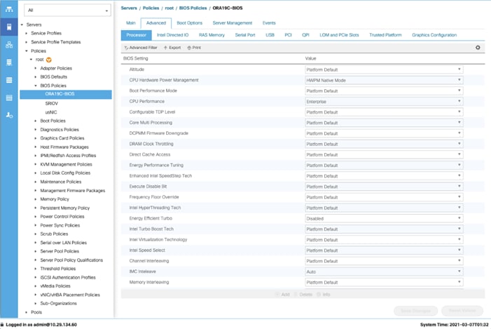
9. Set the following within the RAS Memory tab:
a. Memory RAS configuration: ADDDC Sparing
10. Click Save Changes and then click OK.
![]() In this solution, we created two adapter policies; “Ethernet Adapter Policy” and “Fibre Channel Adapter Policy.” We also configured “Ethernet Adapter Policy” for the Public and Private Network Interface Traffic and the second one “Fibre Channel Adapter Policy” for NVMe FC Storage Network Interface Traffic as explained in the following sections.
In this solution, we created two adapter policies; “Ethernet Adapter Policy” and “Fibre Channel Adapter Policy.” We also configured “Ethernet Adapter Policy” for the Public and Private Network Interface Traffic and the second one “Fibre Channel Adapter Policy” for NVMe FC Storage Network Interface Traffic as explained in the following sections.
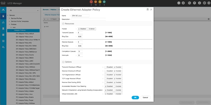
Create Adapter Policy for Ethernet Traffic (Public and Private Network Interfaces)
To create an Adapter Policy for the UCS environment, follow these steps:
1. In Cisco UCS Manager, click the Servers tab in the navigation pane.
2. Select Policies > root > right-click Adapter Policies.
3. Select Create Ethernet Adapter Policy.
4. Provide a name for the Ethernet adapter policy as ORA19C-Linux. Change the following fields and click Save Changes:
a. Resources:
◦ Transmit Queues: 8
◦ Ring Size: 4096
◦ Receive Queues: 8
◦ Completion Queues: 16
◦ Interrupts: 32
b. Options:
◦ Receive Side Scaling (RSS): Enabled
◦ Configure the adapter policy as shown below.
![]() RSS distributes network receive processing across multiple CPUs in multiprocessor systems. This can be one of the following.
RSS distributes network receive processing across multiple CPUs in multiprocessor systems. This can be one of the following.
![]() Disabled—Network receive processing is always handled by a single processor even if additional processors are available.
Disabled—Network receive processing is always handled by a single processor even if additional processors are available.
![]() Enabled—Network receive processing is shared across processors whenever possible.
Enabled—Network receive processing is shared across processors whenever possible.
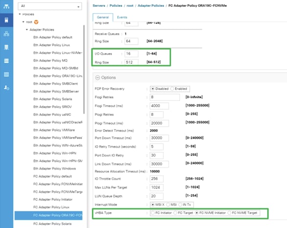
Create Adapter Policy for Fibre Chanel (NVMe/FC Storage Network Interfaces)
To create an Adapter Policy for the UCS environment, follow these steps:
1. In Cisco UCS Manager, click the Servers tab in the navigation pane.
2. Select Policies > root > right-click Adapter Policies.
3. Select Create Fibre Channel Adapter Policy.
4. Provide a name for the FC Adapter Policy and change the following fields and clink Save changes when you are finished:
a. Resources:
◦ I/O Queues: 16
b. Options:
◦ vHBA Type: FC NVMe Initiator
◦ Max LUNs Per Target: 1024
The NVMe/FC Adapter is configured as shown below:
Configure Update Default Maintenance Policy
To update the default Maintenance Policy, follow these steps:
1. In Cisco UCS Manager, click the Servers tab in the navigation pane.
2. Select Policies > root > Maintenance Policies > Default.
3. Change the Reboot Policy to User Ack.
4. Click Save Changes.
5. Click OK to accept the changes.
Configure Host Firmware Policy
Firmware management policies allow the administrator to choose the corresponding packages for a given server configuration. These policies often include packages for adapter, BIOS, board controller, FC adapters, host bus adapter (HBA) option ROM, and storage controller properties.
To create the default firmware management policy in the Cisco UCS environment, follow these steps:
1. In Cisco UCS Manager, click Servers.
2. Expand Policies > root.
3. Expand Host Firmware Packages and right-click to “Create Host Firmware Policy.”
4. Give the policy name as 4.1-3b and select the Blade and Rack Packages as shown below.
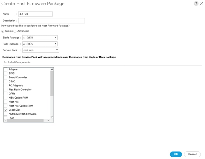
5. Click OK, to create the host firmware package for this UCSM version.
Configure vNIC and vHBA Template
![]() For this solution, we created two vNIC template for Public Network and Private Network Traffic. We will use these vNIC templates during creation of Service Profile later in this section.
For this solution, we created two vNIC template for Public Network and Private Network Traffic. We will use these vNIC templates during creation of Service Profile later in this section.
Create Public and Private vNIC Template
To create vNIC (virtual network interface card) template for the UCS environment, follow these steps:
1. In Cisco UCS Manager, click the LAN tab in the navigation pane.
2. Select Policies > root > vNIC Templates > Right-click to vNIC Template and Select "Create vNIC Template."
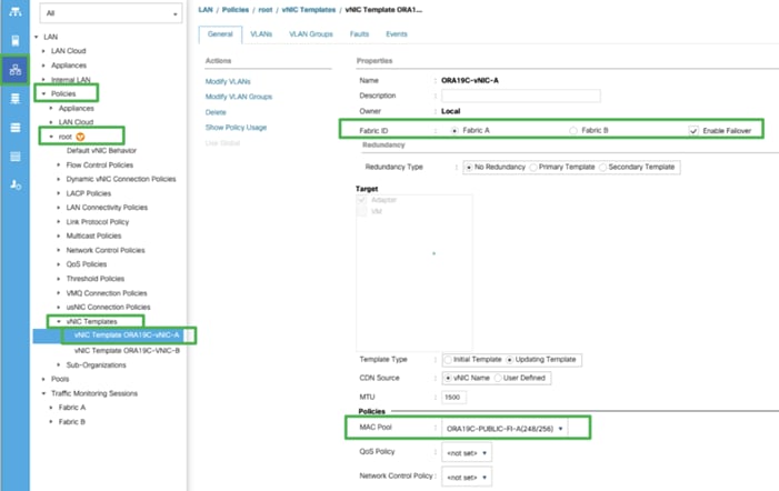
3. Enter ORA19C-vNIC-A as the vNIC template name and keep Fabric A selected.
4. Select the Enable Failover checkbox for high availability of the vNIC.
![]() Selecting Failover is a critical step to improve link failover time by handling it at the hardware level, and to guard against NIC any potential for NIC failure not being detected by the virtual switch.
Selecting Failover is a critical step to improve link failover time by handling it at the hardware level, and to guard against NIC any potential for NIC failure not being detected by the virtual switch.
5. Select Template Type as Updating Template
6. Under VLANs, select the checkboxes default and Public_Traffic and set Native-VLAN as the Public_Traffic.
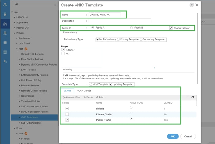
7. Keep MTU value 1500 for Public Network Traffic
8. In the MAC Pool list, select ORA19C-PUBLIC-FI-A.
9. Click OK to create the vNIC template as shown below.
10. Click OK to finish.
11. Similarly, create another vNIC template for Private Network Traffic with few changes.
12. Enter ORA19C-vNIC-B as the vNIC template name for Private Network Traffic.
13. Select the Fabric B and Enable Failover for Fabric ID options.
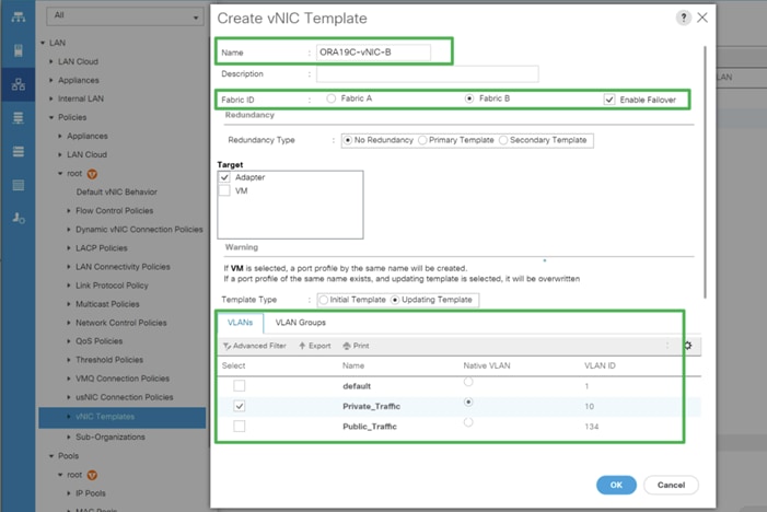
14. Select Template Type as Updating Template.
15. Under VLANs, select the checkboxes default and Private_Traffic and set Native-VLAN as the Private_Traffic.
16. Set MTU value to 9000 and MAC Pool as ORA19C-PRIVATE-FI-B.
17. Click OK to create the vNIC template.
Create Storage vHBA Template
For this solution, we created two vHBA as ORA19C-vHBA-A and ORA19C-vHBA-B.
To create virtual host bus adapter (vHBA) templates for the Cisco UCS environment, follow these steps:
1. In Cisco UCS Manager, click the SAN tab in the navigation pane.
2. Select Policies > root > right-click vHBA Templates > select “Create vHBA Template” to create vHBA.
3. Enter the name ORA19C-vHBA-A and keep Fabric A selected.
4. Select VSAN as VSAN-A and template type to Updating Template.
5. Select WWPN Pool as ORA19C-WWPN-A from the drop-down list as shown below.
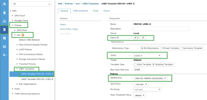
6. Click OK to create first vHBA.
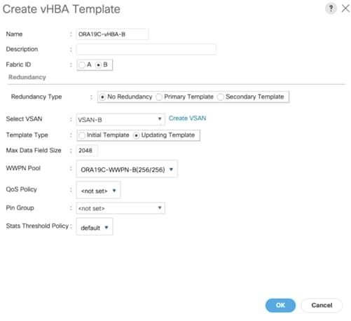
7. Create the second vHBA and change the name as ORA-vHBA-B.
8. Select the Fabric ID as B, template type to Updating Template and WWPN as ORA19C-WWPN-B as shown below.
Create Server Boot Policy for SAN Boot
All Oracle nodes were set to boot from SAN for the Cisco Validated Design as part of the Service Profile template. The benefits of booting from SAN are numerous; disaster recovery, lower cooling, and power requirements for each server since a local drive is not required, and better performance, name just a few. We strongly recommend using “Boot from SAN” to realize full benefits of Cisco UCS stateless computing feature such as service profile mobility.
This process applies to a Cisco UCS environment in which the storage SAN ports are configured in the following sections.
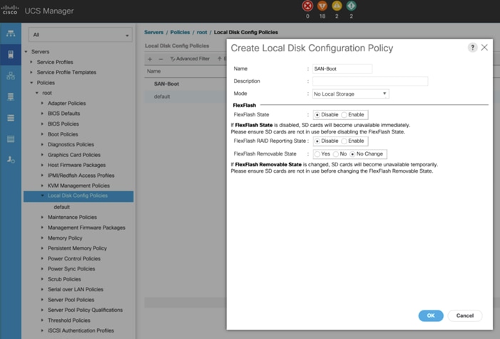
Create Local Disk Configuration Policy
A Local disk configuration for the Cisco UCS is necessary if the servers in the environments have a local disk. To configure Local disk policy, follow these steps:
1. Go to Cisco UCS Manager and then go to Servers > Policies > root > Boot Policies.
2. Right-click and select Create Boot Policy. Enter SAN-Boot for the name of the boot policy.
3. Change the mode to “No Local Storage.”
4. Click OK to create the policy as shown below.
Create SAN Boot Policy
To create SAN Boot Policy, you need to enter the WWPN of NetApp Storage as explained below.
The screenshot below shows both the NetApp AFF A800 Controller FC Ports and related WWPN.
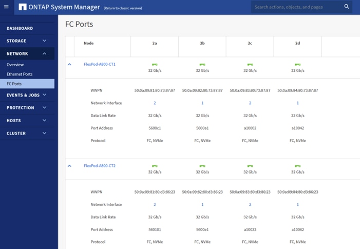
For this solution, we created four FC Logical Interfaces (LIFs) on Storage Controller Node 1 (node1_lif02a, node1_lif02b, node1_lif02c and node1_lif02d) and four FC LIFs on Storage Controller Node 2 (node2_lif02a, node2_lif02b, node2_lif02c and node2_lif02d) as shown below.
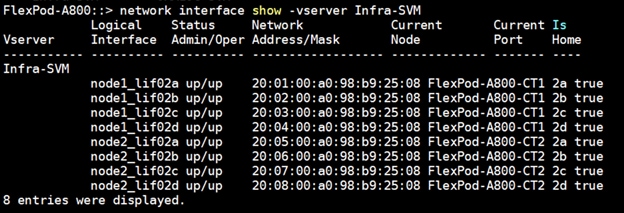
The SAN boot policy configures the SAN Primary's primary-target to be network interface node1_lif02a on NetApp storage cluster and SAN Primary's secondary-target to be network interface node2_lif02a on NetApp storage cluster. Similarly, the SAN Secondary’s primary-target to be network interface node1_lif02c on NetApp storage cluster and SAN Secondary's secondary-target to be network interface node2_lif02c on NetApp storage cluster. This multiple FC ports selection will allow the server node to be highly availability in case of any storage controller failure. Login into NetApp storage controller and verify all the port information is correct. This information can be found in the NetApp Storage GUI under Network > Network Interfaces.
You have to create SAN Primary (hba0) and SAN Secondary (hba1) in SAN Boot Policy by entering the WWPN of NetApp Storage LIFs as explained below.
To create Boot Policy for the Cisco UCS environment, follow these steps:
1. Go to Cisco UCS Manager and then go to Servers > Policies > root > Boot Policies and then right-click to Create Boot Policy as shown below.
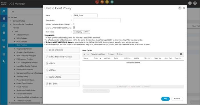
2. Expand the Local Devices drop-down menu and Choose Add CD/DVD.
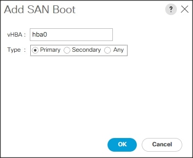
3. Expand the vHBAs drop-down menu and select Add SAN Boot.
4. In the Add SAN Boot dialog box, select Type as “Primary” and name vHBA as “hba0.” Click OK to add SAN Boot.
![]() The SAN boot paths and targets will include primary and secondary options in order to maximize resiliency and number of paths
The SAN boot paths and targets will include primary and secondary options in order to maximize resiliency and number of paths
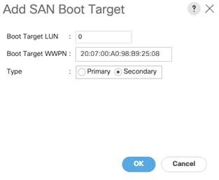
5. Select Add SAN Boot Target to enter WWPN address of storage LIF. Keep 0 as the value for Boot Target LUN. Enter the WWPN of NetApp Storage cluster interface node1_lif02a and add SAN Boot Primary Target.

6. Add secondary SAN Boot target into same hba0, enter boot target LUN as 0 and WWPN of NetApp Storage cluster interface node2_lif02a and add SAN Boot Secondary Target.

7. From the vHBA drop-down list and Choose Add SAN Boot.
8. In the Add SAN Boot dialog box, enter "hba1" in the vHBA field.
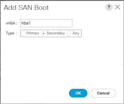
9. Click OK to SAN Boot. Then choose add SAN Boot Target
10. Enter 0 as the value for Boot Target LUN. Enter the WWPN of NetApp Storage cluster interface node1_lif02c and add SAN Boot Primary Target.

11. Add secondary SAN Boot target into same hba1 and enter boot target LUN as 0 and WWPN of NetApp Storage cluster interface node2_lif02c and add SAN Boot Secondary Target.
12. After creating the FC boot policies, you can review the boot order in the UCS Manager GUI as shown below.
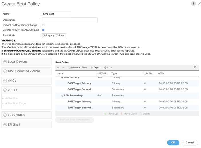
13. Click OK to finish creating SAN_Boot Policy.
![]() For this solution, we created one Boot Policy as “SAN_Boot.” For all eight Oracle Database RAC Nodes (flex1, flex2, flex3, flex4, flex5, flex6, flex7 and flex8), we will assign this boot policy to the Service Profiles as explained in the following section.
For this solution, we created one Boot Policy as “SAN_Boot.” For all eight Oracle Database RAC Nodes (flex1, flex2, flex3, flex4, flex5, flex6, flex7 and flex8), we will assign this boot policy to the Service Profiles as explained in the following section.
Create and Configure Service Profile Template
Service profile templates enable policy-based server management that helps ensure consistent server resource provisioning suitable to meet predefined workload needs.
The Cisco UCS service profiles with SAN boot policy provides the following benefits:
● Scalability - Rapid deployment of new servers to the environment in a very few steps.
● Manageability - Enables seamless hardware maintenance and upgrades without any restrictions.
● Flexibility - Easy to repurpose physical servers for different applications and services as needed.
● Availability - Hardware failures are not impactful and critical. In rare case of a server failure, it is easier to associate the logical service profile to another healthy physical server to reduce the impact.
For this solution, we will create one Service Profile Template “ORA19C_FLEXPOD” using boot policy created earlier to utilize four LIF ports from NetApp Storage for high-availability in case of any FC links go down.
Create Service Profile Template
To create a service profile template, follow these steps:
1. In the Cisco UCS go to Servers > Service Profile Templates > root and right-click to Create Service Profile Template as shown below:
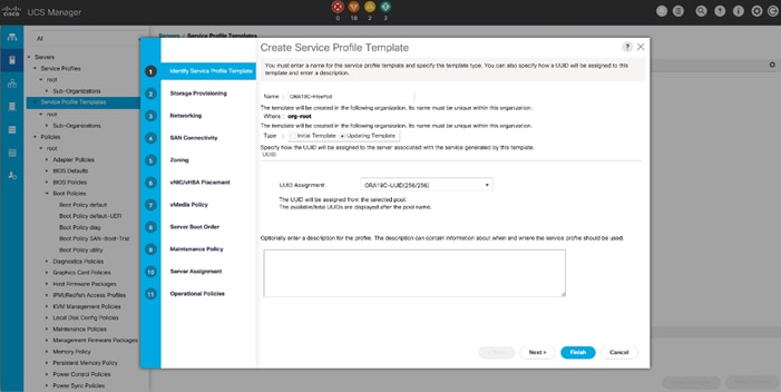
2. Enter the Service Profile Template name, select the UUID Pool that was created earlier, and click Next.
3. Select Local Disk Configuration Policy to SAN-Boot as no Local Storage.
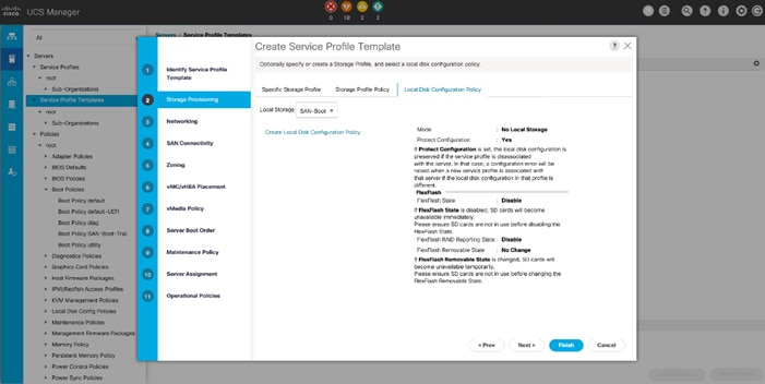
4. In the networking window, select Expert and click Add to create vNICs that the server should use to connect to the LAN
![]() In this solution, we created two vNIC. We have given name to first vNIC as “eth0” and second vNIC as “eth1”.
In this solution, we created two vNIC. We have given name to first vNIC as “eth0” and second vNIC as “eth1”.
5. As shown below in the Create vNIC menu, enter the name “eth0” and check the box for “Use vNIC Template” option. Select vNIC Template “ORA19C-vNIC-A” with Ethernet Adapter Policy as “ORA19C-Linux” which was created earlier.
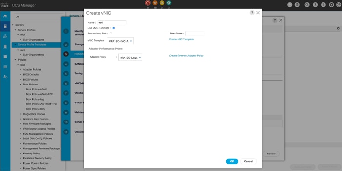
6. Add the second vNIC “eth1” and check the box for “Use vNIC Template” option. Select vNIC Template ORA19C-vNIC-B with Ethernet Adapter Policy as ORA19C-Linux.
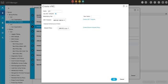
As shown below, we configured two vNICs as eth0 and eth1 so that Servers should use to connect to the LAN.
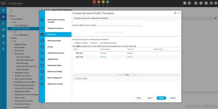
7. When vNICs are created, click Next.
8. In the SAN Connectivity menu, select Expert to configure the SAN connectivity. Select WWNN (World Wide Node Name) pool, which was created earlier.
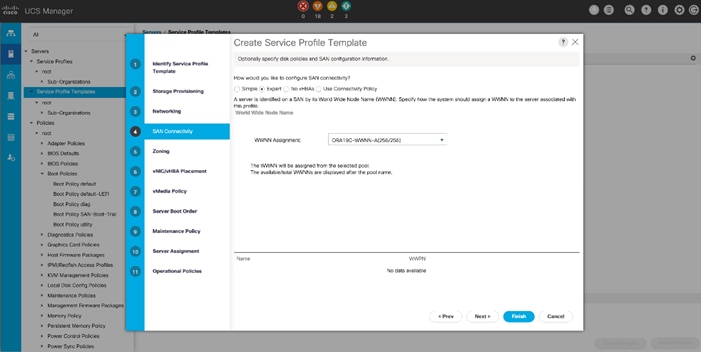
9. Click Add to add vHBAs as explained below.
![]() For this solution, we configured 4 vHBA as 2 vHBA for SAN Boot and 2 vHBA for NVMe/FC. vHBA0 and vHBA1 are configured for carrying FC Network Traffic & Boot from SAN through MDS-A and MDS-B Switch while vHBA2 and vHBA3 are configured for NVMe/FC Network Traffic (Oracle RAC Storage Traffic) through MDS-A and MDS-B Switch.
For this solution, we configured 4 vHBA as 2 vHBA for SAN Boot and 2 vHBA for NVMe/FC. vHBA0 and vHBA1 are configured for carrying FC Network Traffic & Boot from SAN through MDS-A and MDS-B Switch while vHBA2 and vHBA3 are configured for NVMe/FC Network Traffic (Oracle RAC Storage Traffic) through MDS-A and MDS-B Switch.
The following four vHBA are created as follows:
● hba0 using vHBA Template ORA19C-vHBA-A and FC Adapter Policy as “Linux”
● hba1 using vHBA Template ORA19C-vHBA-B and FC Adapter Policy as “Linux”
● hba2 using vHBA Template ORA19C-vHBA-A and FC Adapter Policy as “ORA19C-FCNVMe”
● Hba3 using vHBA Template ORA19C-vHBA-B and FC Adapter Policy as “ORA19C-FCNVMe”
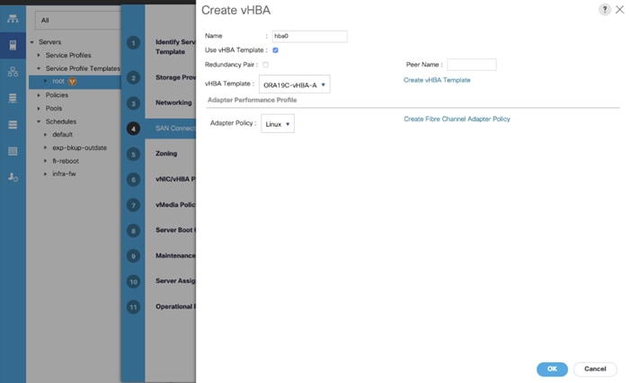
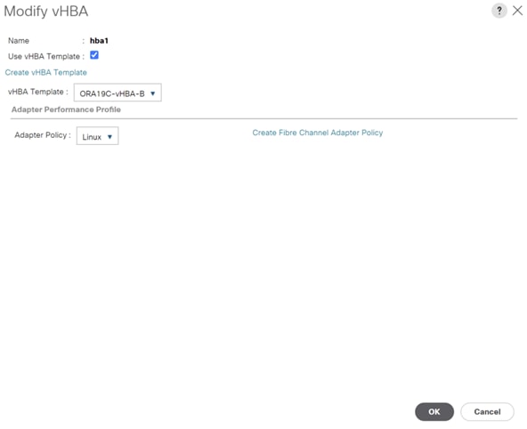
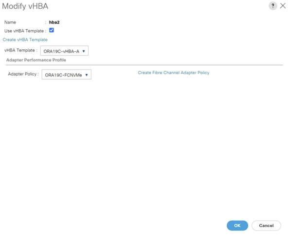
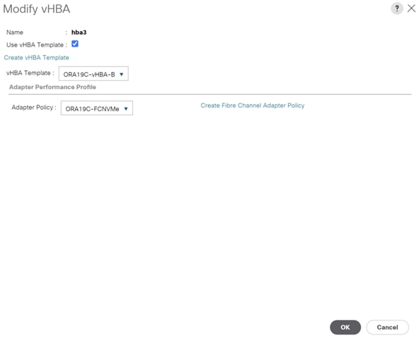
Four vHBAs are configured as shown below.
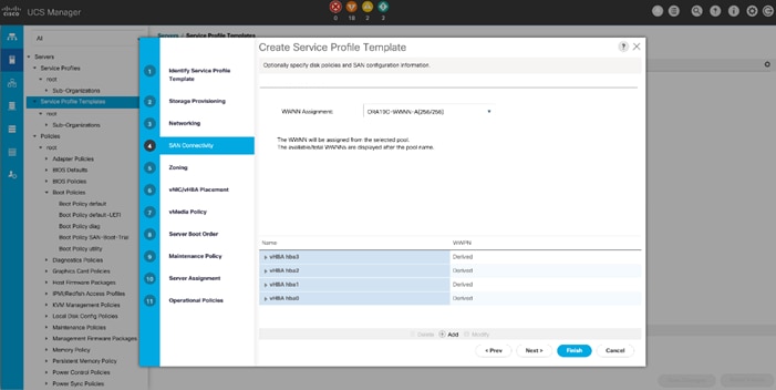
10. Click Next to proceed into zoning menu.
11. For this Oracle RAC Configuration, the Cisco MDS 9132T is used for zoning. So, skip zoning and click Next.
12. In vNIC/vHBA Placement menu, keep the option as Let System Perform Placement.
13. For this solution, we didn’t configure any vMedia Policy, click Next.
14. In the Server Boot Order menu, select SAN_Boot for the Boot Policy which was created earlier and click Next.
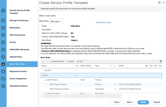
15. The maintenance policy was not selected in this configuration, click Next.
16. In Server Assignment menu, select “ORA19C-SERVER-POOL” as Pool Assignment which we created earlier and “all-chassis” option into Server Pool Qualification selection. In the Firmware Management option, click “4.1-3b” as Host Firmware Package which we created earlier. Click Next.
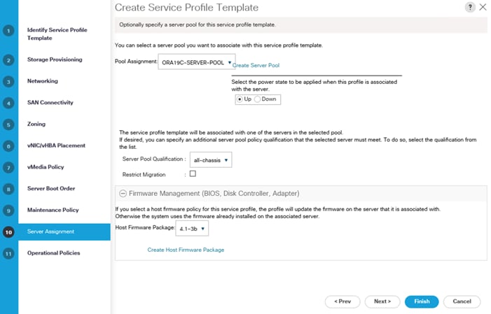
17. Select the BIOS Policy ORA19C_BIOS in the BIOS.
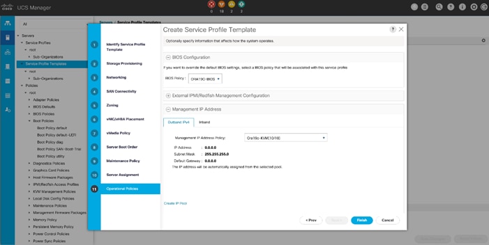
18. Select Management IP Address and then click the Management IP Address Policy “Ora19c-KVM” which was created earlier.
19. Click Finish to create Service Profile Template “ORA19C-FlexPod.”
Now you’ve created one Service profile template “ORA19C_FlexPod” having four vHBAs and two vNICs. This service profile template will be used to create eight service profiles for eight oracle RAC nodes as FLEX1, FLEX2, FLEX3, FLEX4, FLEX5, FLEX6, FLEX7 and FLEX8 as explained in the next section.
Create Service Profiles from Template and Associate to Servers
Create Service Profiles from Template
![]() We created eight Service profiles for all eight Oracle RAC nodes as explained below.
We created eight Service profiles for all eight Oracle RAC nodes as explained below.
For all eight Linux Oracle RAC Nodes (flex1, flex2, flex3, flex4, flex5, flex6, flex7 and flex8), you will create eight Service Profiles as FLEX1, FLEX2, FLEX3, FLEX4, FLEX5, FLEX6, FLEX7 and FLEX8 from the template “ORA19C_FlexPod.”
To create Service Profiles from Template, follow these steps:
1. Go to Servers > Service Profiles > root > and right-click Create Service Profiles from Template.
2. Select the Service profile template ORA19C_FlexPod, previously created and name the service profile “FLEX.”
3. To create eight service profiles, enter Number of Instances as 8. This process will create service profiles as FLEX1, FLEX2, FLEX3, FLEX4, FLEX5, FLEX6, FLEX7 and FLEX8
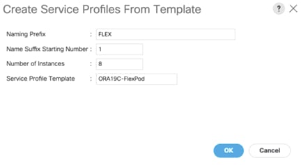
4. When the service profiles are created, associate them to the servers as described in the following section.
Associate Service Profiles to the Servers
To associate service profiles to the servers, follow these steps:
1. Under the server tab, right-click the name of service profile you want to associate with the server and select the option "Change Service Profile Association.”
2. In the Change Service Profile Association page, from the Server Assignment drop-down list, select the existing server that you would like to assign, and click OK.
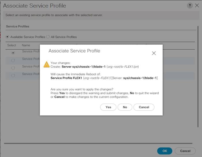
You have assigned, service profiles FLEX1 to Chassis 1 Server 1, service profile FLEX2 to Chassis 1 Server 2, service profiles FLEX3 to Chassis 1 Server 3 and service profiles FLEX4 to Chassis 1 Server 4.
Similarly, you have assigned, service profiles FLEX5 to Chassis 2 Server 1, service profile FLEX6 to Chassis 2 Server 2, service profiles FLEX7 to Chassis 2 Server 3 and service profiles FLEX8 to Chassis 2 Server 4.
1. Make sure all the service profiles are associated.
2. As shown above, make sure all the server nodes have no major or critical fault and all are in operable state as well.
This completes the configuration required for Cisco UCS Manager Setup.
![]() Additional server pools, service profile templates, and service profiles can be created in the respective organizations to add more servers to the FlexPod unit. All other pools and policies are at the root level and can be shared among the organizations.
Additional server pools, service profile templates, and service profiles can be created in the respective organizations to add more servers to the FlexPod unit. All other pools and policies are at the root level and can be shared among the organizations.
This section provides a detailed procedure for configuring the Cisco MDS 9132T Switches.
![]() Follow these steps precisely because failure to do so could result in an improper configuration.
Follow these steps precisely because failure to do so could result in an improper configuration.
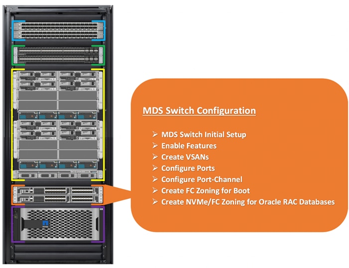
We connected the MDS Switches to Fabric Interconnects and NetApp AFF A800 Storage System as shown below.
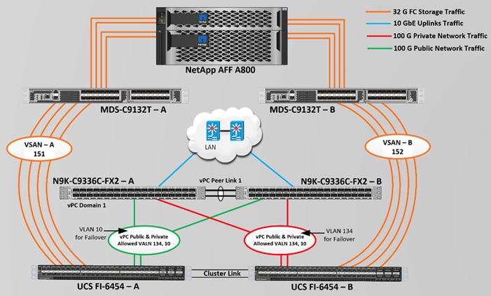
For this solution, we connected four ports (ports 1 to 4) of MDS Switch A to Fabric Interconnect A (ports 1-4). Similarly, we connected four ports (ports 1 to 4) of MDS Switch B to Fabric Interconnect B (ports 1-4). All ports carry 32 Gb/s FC Traffic. Table 9 lists the port connectivity of the Cisco MDS Switches to the Fabric Interconnects.
Table 9. MDS Switch Connectivity to the Fabric Interconnects
| MDS Switch |
MDS Switch Port |
FI Ports |
Fabric Interconnect |
| MDS Switch A |
FC Port 1/1 |
FI-A Port 1/1 |
Fabric Interconnect A (FI-A) |
| FC Port 1/2 |
FI-A Port 1/2 |
||
| FC Port 1/3 |
FI-A Port 1/3 |
||
| FC Port 1/4 |
FI-A Port 1/4 |
||
| MDS Switch B |
FC Port 1/1 |
FI-B Port 1/1 |
Fabric Interconnect B (FI-B) |
| FC Port 1/2 |
FI-B Port 1/2 |
||
| FC Port 1/3 |
FI-B Port 1/3 |
||
| FC Port 1/4 |
FI-B Port 1/4 |
For this solution, we connected four ports (ports 5 to 8) of MDS Switch A to the NetApp AFF A800 Storage controller. Similarly, we connected four ports (ports 5 to 8) of MDS Switch B to the NetApp AFF A800 Storage controller. All ports carry 32 Gb/s FC Traffic. Table 10 lists the port connectivity of the Cisco MDS Switches to NetApp AFF A800 Controller.
Table 10. MDS Switch Connectivity to the NetApp AFF A700s Storage
| MDS Switch |
MDS Switch Port |
NetApp Storage Controller |
NetApp Controller Ports |
NetApp Port Description |
| MDS Switch A |
FC Port 1/5 |
NetApp AFF A800 Controller 1 |
FC Port – 2a |
FlexPod-A800-CT1 – Port 2a |
| FC Port 1/6 |
NetApp AFF A800 Controller 1 |
FC Port – 2b |
FlexPod-A800-CT1 – Port 2b |
|
| FC Port 1/7 |
NetApp AFF A800 Controller 2 |
FC Port – 2a |
FlexPod-A800-CT2 – Port 2a |
|
| FC Port 1/8 |
NetApp AFF A800 Controller 2 |
FC Port – 2b |
FlexPod-A800-CT2 – Port 2b |
|
| MDS Switch B |
FC Port 1/5 |
NetApp AFF A800 Controller 1 |
FC Port – 2c |
FlexPod-A800-CT1 – Port 2c |
| FC Port 1/6 |
NetApp AFF A800 Controller 1 |
FC Port – 2d |
FlexPod-A800-CT1 – Port 2d |
|
| FC Port 1/7 |
NetApp AFF A800 Controller 2 |
FC Port – 2c |
FlexPod-A800-CT2 – Port 2c |
|
| FC Port 1/8 |
NetApp AFF A800 Controller 2 |
FC Port – 2d |
FlexPod-A800-CT2 – Port 2d |
To configure feature on MDS Switches, follow this step:
1. Login as admin user into the MDS Switch A and MDS Switch B and run the following commands:
config terminal
feature npiv
feature fport-channel-trunk
copy running-config startup-config
To create VSANs, follow these steps:
1. Login as admin user into MDS Switch A.
2. Create VSAN 151 for Storage Traffic and configure ports by running the following commands:
config terminal
vsan database
vsan 151
vsan 151 name "VSAN-FI-A"
vsan 151 interface fc 1/1-12
zone smart-zoning enable vsan 151
exit
interface port-channel251
switchport trunk allowed vsan 151
switchport description ORA19C-FlexPod-FI-A
switchport rate-mode dedicated
switchport trunk mode off
no shutdown
interface fc1/1
switchport description ORA19C-FlexPod-FI-A-1/1
switchport trunk mode off
port-license acquire
channel-group 251 force
no shutdown
interface fc1/2
switchport description ORA19C-FlexPod-FI-A-1/2
switchport trunk mode off
port-license acquire
channel-group 251 force
no shutdown
interface fc1/3
switchport description ORA19C-FlexPod-FI-A-1/3
switchport trunk mode off
port-license acquire
channel-group 251 force
no shutdown
interface fc1/4
switchport description ORA19C-FlexPod-FI-A-1/4
switchport trunk mode off
port-license acquire
channel-group 251 force
no shutdown
interface fc1/5
switchport trunk allowed vsan 151
switchport description FlexPod-A800-01-2a
switchport trunk mode off
port-license acquire
no shutdown
interface fc1/6
switchport trunk allowed vsan 151
switchport description FlexPod-A800-01-2b
switchport trunk mode off
port-license acquire
no shutdown
interface fc1/7
switchport trunk allowed vsan 151
switchport description FlexPod-A800-02-2a
switchport trunk mode off
port-license acquire
no shutdown
interface fc1/8
switchport trunk allowed vsan 151
switchport description FlexPod-A800-02-2b
switchport trunk mode off
port-license acquire
no shutdown
copy running-config startup-config
3. Login as admin user into MDS Switch B.
4. Create VSAN 152 for Storage Traffic and configure ports by running the following commands:
config terminal
vsan database
vsan 152
vsan 152 name "VSAN-FI-B"
vsan 152 interface fc 1/1-12
zone smart-zoning enable vsan 152
exit
interface port-channel252
switchport trunk allowed vsan 152
switchport description ORA19C-FlexPod-FI-B
switchport rate-mode dedicated
switchport trunk mode off
interface fc1/1
switchport description ORA19C-FlexPod-FI-B-1/1
switchport trunk mode off
port-license acquire
channel-group 252 force
no shutdown
interface fc1/2
switchport description ORA19C-FlexPod-FI-B-1/2
switchport trunk mode off
port-license acquire
channel-group 252 force
no shutdown
interface fc1/3
switchport description ORA19C-FlexPod-FI-B-1/3
switchport trunk mode off
port-license acquire
channel-group 252 force
no shutdown
interface fc1/4
switchport description ORA19C-FlexPod-FI-B-1/4
switchport trunk mode off
port-license acquire
channel-group 252 force
no shutdown
interface fc1/5
switchport trunk allowed vsan 152
switchport description FlexPod-A800-01-2c
switchport trunk mode off
port-license acquire
no shutdown
interface fc1/6
switchport trunk allowed vsan 152
switchport description FlexPod-A800-01-2d
switchport trunk mode off
port-license acquire
no shutdown
interface fc1/7
switchport trunk allowed vsan 152
switchport description FlexPod-A800-02-2c
switchport trunk mode off
port-license acquire
no shutdown
interface fc1/8
switchport trunk allowed vsan 152
switchport description FlexPod-A800-02-2d
switchport trunk mode off
port-license acquire
no shutdown
This procedure sets up the Fibre Channel connections between the Cisco MDS 9132T switches, the Cisco UCS Fabric Interconnects, and the NetApp AFF Storage systems. Before you configure the zoning details, decide how many paths are needed for each LUN and extract the WWPN numbers for each of the HBAs from each server.
For this solution, we created 4 vHBAs on each server node. As listed in Table 3 and into UCS Service Profile Template configuration section, we have configured vHBA0 and vHBA1 for carrying FC Network Traffic & Boot from SAN through MDS-A and MDS-B Switch. We have configured vHBA2 and vHBA3 for NVMe/FC Network Traffic (Oracle RAC Storage Traffic) through MDS-A and MDS-B Switch.
To create and configure the Fibre channel zoning, follow these steps:
1. Log into the Cisco UCS Manager > Equipment > Chassis > Servers and select the desired server. On the right-hand menu, click the Inventory tab and HBA's tab to get the WWPN of HBA's as shown below:
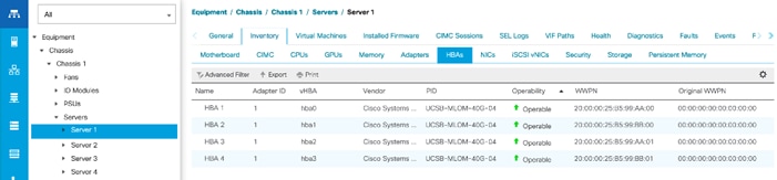
2. Login into the NetApp storage controller and extract the WWPN of FC LIFs configured and verify all the port information is correct. This information can be found in the NetApp Storage GUI under Network > Network Interfaces.
Now you have configured 2 SVMs. One SVM named “Infra-SVM” was configured to carry FC network traffic for SAN Boot while the second SVM, named “ORA19C-SVM” was configured to run NVMe/FC Network Traffic for Oracle RAC Databases. The screenshot below shows the allowed protocols configured for both SVMs.

The screenshot below shows the network interface, WWPN and ports connectivity configured for NetApp AFF A800 Storage Controller.
For SVM “Infra-SVM”, four FC Logical Interfaces (LIFs) are created on storage controller cluster node 1 (node1_lif02a, node1_lif02b, node1_lif02c and node1_lif02d) and four Fibre Channel LIFs are created on storage controller cluster node 2 (node2_lif02a, node2_lif02b, node2_lif02c and node2_lif02d).
For SVM “ORA19C-SVM”, two NVMe Logical Interfaces (LIFs) are created on storage controller cluster node 1 (node1_lif02a and node1_lif02c) and two NVMe LIFs are created on storage controller cluster node 2 (node2_lif02a and node2_lif02c).
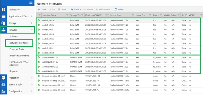
![]() You can also obtain this information by login to the storage cluster and run the network interface show command.
You can also obtain this information by login to the storage cluster and run the network interface show command.
Create Device Aliases for Zoning on MDS Switch A
To configure device aliases and zones for FC and NVMe/FC Network data paths on MDS switch A, follow these steps:
1. Login as admin user and run the following commands MDS switch A:
configure terminal
device-alias database
device-alias name Flex1-hba0 pwwn 20:00:00:25:b5:99:aa:00
device-alias name Flex1-hba2 pwwn 20:00:00:25:b5:99:aa:01
device-alias name Flex2-hba0 pwwn 20:00:00:25:b5:99:aa:02
device-alias name Flex2-hba2 pwwn 20:00:00:25:b5:99:aa:03
device-alias name Flex3-hba0 pwwn 20:00:00:25:b5:99:aa:04
device-alias name Flex3-hba2 pwwn 20:00:00:25:b5:99:aa:05
device-alias name Flex4-hba0 pwwn 20:00:00:25:b5:99:aa:06
device-alias name Flex4-hba2 pwwn 20:00:00:25:b5:99:aa:07
device-alias name Flex5-hba0 pwwn 20:00:00:25:b5:99:aa:08
device-alias name Flex5-hba2 pwwn 20:00:00:25:b5:99:aa:09
device-alias name Flex6-hba0 pwwn 20:00:00:25:b5:99:aa:0a
device-alias name Flex6-hba2 pwwn 20:00:00:25:b5:99:aa:0b
device-alias name Flex7-hba0 pwwn 20:00:00:25:b5:99:aa:0c
device-alias name Flex7-hba2 pwwn 20:00:00:25:b5:99:aa:0d
device-alias name Flex8-hba0 pwwn 20:00:00:25:b5:99:aa:0e
device-alias name Flex8-hba2 pwwn 20:00:00:25:b5:99:aa:0f
device-alias name FlexPod-A800-01-2a pwwn 20:01:00:a0:98:b9:25:08
device-alias name FlexPod-A800-01-2b pwwn 20:02:00:a0:98:b9:25:08
device-alias name FlexPod-A800-02-2a pwwn 20:05:00:a0:98:b9:25:08
device-alias name FlexPod-A800-02-2b pwwn 20:06:00:a0:98:b9:25:08
device-alias name A800-NVMe-01-2a pwwn 20:14:00:a0:98:b9:25:08
device-alias name A800-NVMe-02-2a pwwn 20:16:00:a0:98:b9:25:08
device-alias commit
copy run start
Create Device Aliases for Zoning on MDS Switch B
To configure device aliases and zones for the FC and NVMe/FC Network data paths on MDS switch B, follow these steps:
1. Login as admin user and run the following commands on MDS switch B:
configure terminal
device-alias database
device-alias name Flex1-hba1 pwwn 20:00:00:25:b5:99:bb:00
device-alias name Flex1-hba3 pwwn 20:00:00:25:b5:99:bb:01
device-alias name Flex2-hba1 pwwn 20:00:00:25:b5:99:bb:02
device-alias name Flex2-hba3 pwwn 20:00:00:25:b5:99:bb:03
device-alias name Flex3-hba1 pwwn 20:00:00:25:b5:99:bb:04
device-alias name Flex3-hba3 pwwn 20:00:00:25:b5:99:bb:05
device-alias name Flex4-hba1 pwwn 20:00:00:25:b5:99:bb:06
device-alias name Flex4-hba3 pwwn 20:00:00:25:b5:99:bb:07
device-alias name Flex5-hba1 pwwn 20:00:00:25:b5:99:bb:08
device-alias name Flex5-hba3 pwwn 20:00:00:25:b5:99:bb:09
device-alias name Flex6-hba1 pwwn 20:00:00:25:b5:99:bb:0a
device-alias name Flex6-hba3 pwwn 20:00:00:25:b5:99:bb:0b
device-alias name Flex7-hba1 pwwn 20:00:00:25:b5:99:bb:0c
device-alias name Flex7-hba3 pwwn 20:00:00:25:b5:99:bb:0d
device-alias name Flex8-hba1 pwwn 20:00:00:25:b5:99:bb:0e
device-alias name Flex8-hba3 pwwn 20:00:00:25:b5:99:bb:0f
device-alias name FlexPod-A800-01-2c pwwn 20:03:00:a0:98:b9:25:08
device-alias name FlexPod-A800-01-2d pwwn 20:04:00:a0:98:b9:25:08
device-alias name FlexPod-A800-02-2c pwwn 20:07:00:a0:98:b9:25:08
device-alias name FlexPod-A800-02-2d pwwn 20:08:00:a0:98:b9:25:08
device-alias name A800-NVMe-01-2c pwwn 20:15:00:a0:98:b9:25:08
device-alias name A800-NVMe-02-2c pwwn 20:21:00:a0:98:b9:25:08
device-alias commit
copy run start
For each of the SVM (Infra-SVM and ORA19C-SVM) and its corresponding WWPN, you will create its individual zoning (FC Zoning for Boot and NVMe/FC Zoning for NVMe/FC network traffic).
To configure the SAN Boot on each node, configure the zoning on both MDS switches as detailed in the following sections.
Cisco MDS Switch A
To configure the zones on MDS Switch A, follow these steps:
1. Login as admin user.
2. Create the zones for each server:
configure terminal
zone name Flex1A-Boot vsan 151
member device-alias Flex1-hba0 init
member device-alias FlexPod-A800-01-2a target
member device-alias FlexPod-A800-02-2a target
zone name Flex2A-Boot vsan 151
member device-alias Flex2-hba0 init
member device-alias FlexPod-A800-01-2a target
member device-alias FlexPod-A800-02-2a target
zone name Flex3A-Boot vsan 151
member device-alias Flex3-hba0 init
member device-alias FlexPod-A800-01-2a target
member device-alias FlexPod-A800-02-2a target
zone name Flex4A-Boot vsan 151
member device-alias Flex4-hba0 init
member device-alias FlexPod-A800-01-2a target
member device-alias FlexPod-A800-02-2a target
zone name Flex5A-Boot vsan 151
member device-alias Flex5-hba0 init
member device-alias FlexPod-A800-01-2a target
member device-alias FlexPod-A800-02-2a target
zone name Flex6A-Boot vsan 151
member device-alias Flex6-hba0 init
member device-alias FlexPod-A800-01-2a target
member device-alias FlexPod-A800-02-2a target
zone name Flex7A-Boot vsan 151
member device-alias Flex7-hba0 init
member device-alias FlexPod-A800-01-2a target
member device-alias FlexPod-A800-02-2a target
zone name Flex8A-Boot vsan 151
member device-alias Flex8-hba0 init
member device-alias FlexPod-A800-01-2a target
member device-alias FlexPod-A800-02-2a target
3. Create Zoneset and add all the members:
zoneset name Flex-A vsan 151
member Flex1A-Boot
member Flex2A-Boot
member Flex3A-Boot
member Flex4A-Boot
member Flex5A-Boot
member Flex6A-Boot
member Flex7A-Boot
member Flex8A-Boot
4. Activate the Zoneset and save the configuration:
zoneset activate name Flex-A vsan 151
copy run start
Cisco MDS Switch B
To configure zones on MDS Switch B, follow these steps:
1. Login as admin user.
2. Create the zones for each server:
configure terminal
zone name Flex1B-Boot vsan 152
member device-alias Flex1-hba1 init
member device-alias FlexPod-A800-01-2c target
member device-alias FlexPod-A800-02-2c target
zone name Flex2B-Boot vsan 152
member device-alias Flex2-hba1 init
member device-alias FlexPod-A800-01-2c target
member device-alias FlexPod-A800-02-2c target
zone name Flex3B-Boot vsan 152
member device-alias Flex3-hba1 init
member device-alias FlexPod-A800-01-2c target
member device-alias FlexPod-A800-02-2c target
zone name Flex4B-Boot vsan 152
member device-alias Flex4-hba1 init
member device-alias FlexPod-A800-01-2c target
member device-alias FlexPod-A800-02-2c target
zone name Flex5B-Boot vsan 152
member device-alias Flex5-hba1 init
member device-alias FlexPod-A800-01-2c target
member device-alias FlexPod-A800-02-2c target
zone name Flex6B-Boot vsan 152
member device-alias Flex6-hba1 init
member device-alias FlexPod-A800-01-2c target
member device-alias FlexPod-A800-02-2c target
zone name Flex7B-Boot vsan 152
member device-alias Flex7-hba1 init
member device-alias FlexPod-A800-01-2c target
member device-alias FlexPod-A800-02-2c target
zone name Flex8B-Boot vsan 152
member device-alias Flex8-hba1 init
member device-alias FlexPod-A800-01-2c target
member device-alias FlexPod-A800-02-2c target
3. Create Zoneset and add all the members:
zoneset name Flex-B vsan 152
member Flex1B-Boot
member Flex2B-Boot
member Flex3B-Boot
member Flex4B-Boot
member Flex5B-Boot
member Flex6B-Boot
member Flex7B-Boot
member Flex8B-Boot
4. Activate the Zoneset and save the configuration.
zoneset activate name Flex-B vsan 152
copy run start
To configure the NVMe/FC on each node, configure the zoning on both MDS switches as detailed in the following sections.
Cisco MDS Switch A
To configure NVMe/FsC zones on MDS Switch A, follow these steps:
1. Login as admin user.
2. Create the zones for each server:
configure terminal
zone name Flex1A-NVMe vsan 151
member device-alias Flex1-hba2 init
member device-alias A800-NVMe-01-2a target
member device-alias A800-NVMe-02-2a target
zone name Flex2A-NVMe vsan 151
member device-alias Flex2-hba2 init
member device-alias A800-NVMe-01-2a target
member device-alias A800-NVMe-02-2a target
zone name Flex3A-NVMe vsan 151
member device-alias Flex3-hba2 init
member device-alias A800-NVMe-01-2a target
member device-alias A800-NVMe-02-2a target
zone name Flex4A-NVMe vsan 151
member device-alias Flex4-hba2 init
member device-alias A800-NVMe-01-2a target
member device-alias A800-NVMe-02-2a target
zone name Flex5A-NVMe vsan 151
member device-alias Flex5-hba2 init
member device-alias A800-NVMe-01-2a target
member device-alias A800-NVMe-02-2a target
zone name Flex6A-NVMe vsan 151
member device-alias Flex6-hba2 init
member device-alias A800-NVMe-01-2a target
member device-alias A800-NVMe-02-2a target
zone name Flex7A-NVMe vsan 151
member device-alias Flex7-hba2 init
member device-alias A800-NVMe-01-2a target
member device-alias A800-NVMe-02-2a target
zone name Flex8A-NVMe vsan 151
member device-alias Flex8-hba2 init
member device-alias A800-NVMe-01-2a target
member device-alias A800-NVMe-02-2a target
3. Add all the members into Zoneset:
zoneset name Flex-A vsan 151
member Flex1A-NVMe
member Flex2A-NVMe
member Flex3A-NVMe
member Flex4A-NVMe
member Flex5A-NVMe
member Flex6A-NVMe
member Flex7A-NVMe
member Flex8A-NVMe
4. Activate the Zoneset and save the configuration.
zoneset activate name Flex-A vsan 151
copy run start
Cisco MDS Switch B
To configure NVMe/FC zones on MDS Switch B, follow these steps:
1. Login as admin user.
2. Create the zones for each server:
configure terminal
zone name Flex1B-NVMe vsan 152
member device-alias Flex1-hba3 init
member device-alias A800-NVMe-01-2c target
member device-alias A800-NVMe-02-2c target
zone name Flex2B-NVMe vsan 152
member device-alias Flex2-hba3 init
member device-alias A800-NVMe-01-2c target
member device-alias A800-NVMe-02-2c target
zone name Flex3B-NVMe vsan 152
member device-alias Flex3-hba3 init
member device-alias A800-NVMe-01-2c target
member device-alias A800-NVMe-02-2c target
zone name Flex4B-NVMe vsan 152
member device-alias Flex4-hba3 init
member device-alias A800-NVMe-01-2c target
member device-alias A800-NVMe-02-2c target
zone name Flex5B-NVMe vsan 152
member device-alias Flex5-hba3 init
member device-alias A800-NVMe-01-2c target
member device-alias A800-NVMe-02-2c target
zone name Flex6B-NVMe vsan 152
member device-alias Flex6-hba3 init
member device-alias A800-NVMe-01-2c target
member device-alias A800-NVMe-02-2c target
zone name Flex7B-NVMe vsan 152
member device-alias Flex7-hba3 init
member device-alias A800-NVMe-01-2c target
member device-alias A800-NVMe-02-2c target
zone name Flex8B-NVMe vsan 152
member device-alias Flex8-hba3 init
member device-alias A800-NVMe-01-2c target
member device-alias A800-NVMe-02-2c target
3. Create Zoneset and add all the members.
zoneset name Flex-B vsan 152
member Flex1B-NVMe
member Flex2B-NVMe
member Flex3B-NVMe
member Flex4B-NVMe
member Flex5B-NVMe
member Flex6B-NVMe
member Flex7B-NVMe
member Flex8B-NVMe
4. Activate the Zoneset and save the configuration.
zoneset activate name Flex-B vsan 152
copy run start
To verify the FC ports on the MDS switch, follow these steps:
1. Login as admin user into MDS Switch A and run the “show flogi database vsan 151” to verify all FC ports.
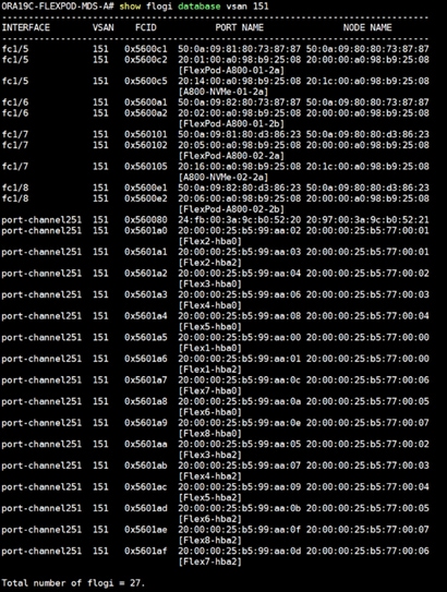
2. Login as admin user into MDS Switch B and run the “show flogi database vsan 152” to verify all FC ports.
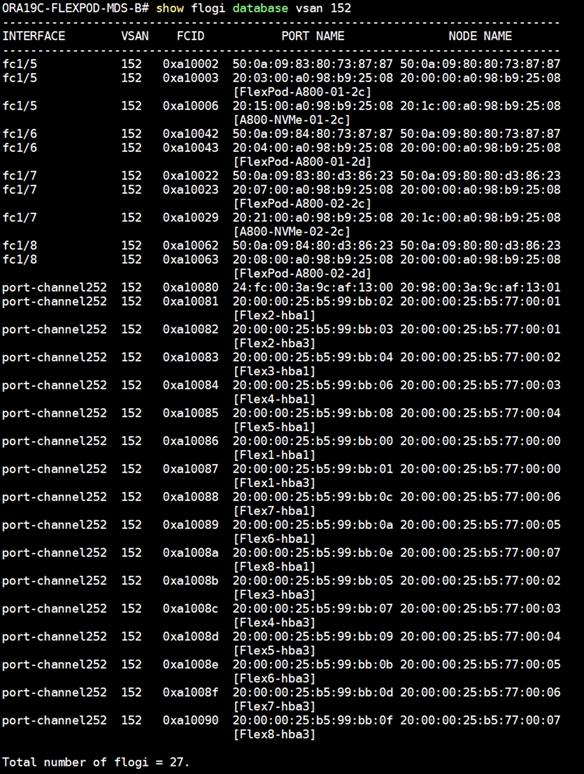
This concludes both MDS Switch configurations.
Configure NetApp AFF A800 Storage
The high-level steps for configuring the NetApp Storage for this solution is shown below:
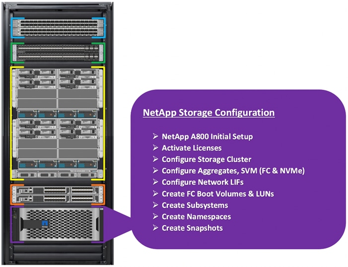
![]() It is beyond the scope of this document to explain the detailed information about the NetApp storage connectivity and infrastructure configuration. For installation and setup instruction for the NetApp AFF A800 System, go to: https://docs.netapp.com/platstor/index.jsp?topic=%2Fcom.netapp.doc.hw-a800-install-setup%2FGUID-91FA78D3-A39E-451D-BB17-6476972A0716.html
It is beyond the scope of this document to explain the detailed information about the NetApp storage connectivity and infrastructure configuration. For installation and setup instruction for the NetApp AFF A800 System, go to: https://docs.netapp.com/platstor/index.jsp?topic=%2Fcom.netapp.doc.hw-a800-install-setup%2FGUID-91FA78D3-A39E-451D-BB17-6476972A0716.html
For more information, go to the Cisco site: https://www.cisco.com/c/en/us/solutions/design-zone/data-center-design-guides/flexpod-design-guides.html
This section describes the storage layout and design considerations for the database deployment. The screenshot below shows the SVM (formally known as Vserver) and FC Interfaces configuration. For this solution, we configured two SVM. The first SVM named as “Infra-SVM” was configured to carry FC network traffic for SAN Boot while the second SVM named as “ORA19C-SVM” was configured to run NVMe/FC Network Traffic for Oracle RAC Databases. The screenshot below shows the allowed protocols configured for both the SVMs.
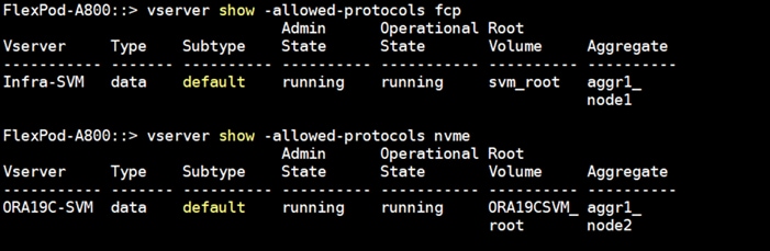
For the FC SVM (Infra-SVM), four FC Logical Interfaces (LIFs) are created on storage controller cluster node 1 (node1_lif02a, node1_lif02b, node1_lif02c and node1_lif02d) and four Fibre Channel LIFs are created on storage controller cluster node 2 (node2_lif02a, node2_lif02b, node2_lif02c and node2_lif02d) as shown below.
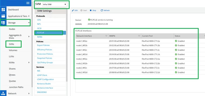
For the NVMe SVM (ORA19C-SVM), two NVMe Logical Interfaces (LIFs) are created on storage controller cluster node 1 (node1_lif02a and node1_lif02c) and two NVMe LIFs are created on storage controller cluster node 2 (node2_lif02a and node2_lif02c).
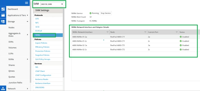
As shown above, for both the storage controller nodes (FlexPod-A800-CT1 and FlexPod-A800-CT2), we have used ports 2a, 2b and 2c, 2d to configure LIFs. WWPN of these LIFs are used for zoning into the MDS switches for storage to MDS connectivity as explained earlier.
For all the database deployment, we have configured two aggregates (one aggregate on each storage node) and each aggregate contains 12 SSD (1.75 TB Each) drives that were subdivided into RAID DP groups as shown below.
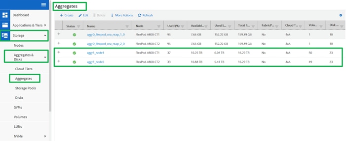
We created 8 LUNs for SAN boot and mapped those with the corresponding Linux host initiators to boot from SAN. For database deployment, we created multiple subsystem and namespaces. We also distributed equal number of subsystems on the storage controller by placing those into the aggregate equally. We will explain the subsystem configuration in the database creation section.
Operating System and Database Deployment
The design goal of the reference architecture was to best represent a real-world environment as closely as possible. As explained in the earlier section, service profile was created within Cisco UCS Manager to rapidly deploy all the stateless servers to deploy an eight node Oracle RAC. SAN boot LUNs for these servers were hosted on the NetApp Storage Cluster to provision the OS on top it. Zoning was performed on the Cisco MDS switches to enable the initiators discover the targets during boot process.
Each Server node has a dedicated single LUN to install operating system. For this solution, we have installed Oracle Linux Server 8.2 (RHCK 4.18.0-193.el8.x86_64) on these LUNs and configured NVMe/FC connectivity with all the prerequisite packages for installing Oracle Software to create an eight node Oracle Multitenant RAC 19c database solution.
The high-level steps to configure Linux Hosts and deploy the Oracle RAC Database solution is shown below:
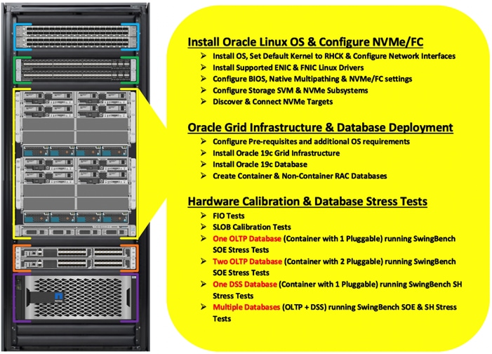
![]() The detailed installation process is not contained in this document, but the following section describes the key steps for OS installation.
The detailed installation process is not contained in this document, but the following section describes the key steps for OS installation.
To Configure OS, follow these steps:
1. Download the Oracle Linux 8.2 OS image from https://edelivery.oracle.com/linux
2. Launch KVM console on desired server by going to tab Equipment > Chassis > Chassis 1 > Servers > Server 1 > from right side windows General > and select KVM Console to open KVM.
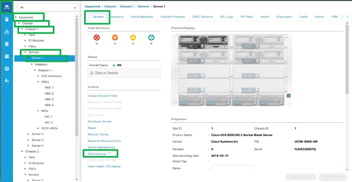
3. Click Accept security and open KVM. Activate Virtual Devices and map the Oracle Linux ISO image from the top right corner menu options, and then reboot the server.
4. When the Server starts booting, it will detect the NetApp Storage active FC paths as shown below. If you see the following message in the KVM console while the server is rebooting along with the target WWPNs, it confirms the setup and zoning is done correctly and boot from SAN will be successful.
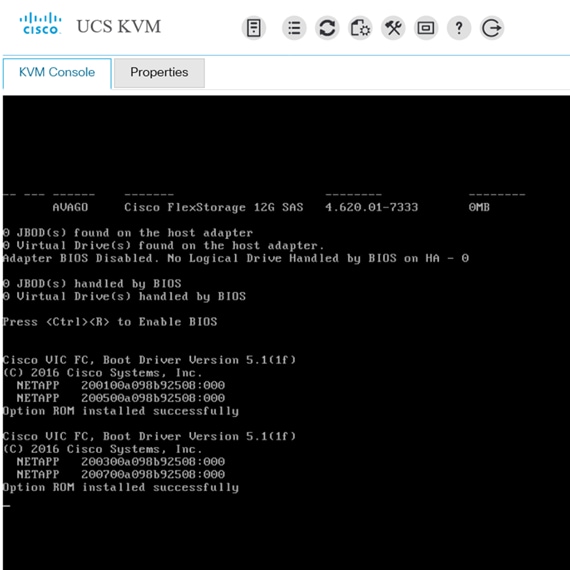
5. During server boot order, it will detect the virtual media connected as Oracle Linux ISO DVD media and it should launch the Oracle Linux OS installer. Select language and assign the Installation destination as NetApp Storage LUN. Apply hostname and click “Configure Network” to configure all network interfaces. Alternatively, you can only configure “Public Network” in this step. You can configure additional interfaces as part of post OS install steps.
6. As a part of additional RPM package, we recommend selecting “Customize Now” option and relevant packages according to your environment.
7. After the OS install finishes, reboot the server, and complete the appropriate registration steps. You can choose to synchronize the time with ntp server. Alternatively, you can choose to use Oracle RAC cluster synchronization daemon (OCSSD). Both ntp and OCSSD are mutually exclusive and OCSSD will be setup during GRID install if ntp is not configured.
Oracle Linux 8 Update 2 ships with two kernels:
● UEK R6 (kernel-uek-5.4.17-2011.1.2.el8uek) for x86_64 (Intel & AMD) and aarch64 (Arm) platform
● RHCK (kernel-4.18.0-193.el8) for x86_64 (Intel & AMD) platform
After installing Oracle Linux 8.2 on all the server nodes (flex1, flex2, flex3, flex4, fle5, flex6, flex7 and flex8), to configure the default kernel to RHCK, follow these steps:
1. Check the list of installed kernel:
[root@flex1 ~]# ls -al /boot/vmlinuz*
lrwxrwxrwx 1 root root 32 Feb 21 23:43 /boot/vmlinuz -> /boot/vmlinuz-4.18.0-193.el8.gv+
-rwxr-xr-x. 1 root root 9226480 Oct 15 17:07 /boot/vmlinuz-0-rescue-8ca6c4cb17ac4fa5aad3028bfb737418
-rwxr-xr-x. 1 root root 9226480 Apr 29 2020 /boot/vmlinuz-4.18.0-193.el8.x86_64
-rwxr-xr-x. 1 root root 8923392 Apr 20 2020 /boot/vmlinuz-5.4.17-2011.1.2.el8uek.x86_64
2. Set the default kernel and reboot the node:
[root@flex1 ~]# grubby --set-default=/boot/vmlinuz-4.18.0-193.el8.x86_64
[root@flex1 ~]# systemctl reboot
3. After the node reboots, verify the default kernel boot:
[root@flex1 ~]# grubby --default-kernel
/boot/vmlinuz-4.18.0-193.el8.x86_64
4. Repeat steps 1-3 and configure the RHCL as the default kernel boot on all the nodes.
Configure Public and Private Network Interfaces
If you have not configured network interfaces during OS installation, then configure it now. Each node must have at least two network interface or network adapters. One network interface is for the public network traffic and the second interface is for the private network traffic (the node interconnects). The server nodes will access FC and NVMe/FC network traffic through vHBA.
To configure public and private network interfaces, follow these steps:
1. Login as a root user into each node and go to /etc/sysconfig/network-scripts/
2. Configure Public network and Private network IP addresses according to your environments.
![]() Configure the Private and Public network with the appropriate IP addresses on all the Oracle RAC nodes
Configure the Private and Public network with the appropriate IP addresses on all the Oracle RAC nodes
Install ENIC and FNIC Linux OS Driver
For this solution, we configured the following ENIC and FNIC drivers:
● ENIC: version: 4.0.0.14-802.74
● FNIC: version: 2.0.0.69-178.0
To install the ENIC and FNIC linux OS driver, follow these steps:
1. Download the supported UCS Linux Drivers “ucs-bxxx-drivers-linux.4.1.3b.iso” from this link: https://software.cisco.com/download/home/283853163/type/283853158/release/4.1(3b)
2. Mount the Driver ISO to Linux Host KVM and Install the relevant supported ENIC and FNIC driver for the Linux OS.
3. Check the current ENIC and FNIC version:
[root@flex1 ~]# cat /sys/module/enic/version
[root@flex1 ~]# cat /sys/module/fnic/version
[root@flex1 ~]# rpm -qa | grep enic
[root@flex1 ~]# rpm -qa | grep fnic
4. Install the supported ENIC and FNIC driver from RPM:
[root@flex1 software]# rpm -ivh kmod-enic-4.0.0.14-802.74.rhel8u2.x86_64.rpm
[root@flex1 software]# rpm -ivh kmod-fnic-2.0.0.69-178.0.rhel8u2.x86_64.rpm
5. Reboot the server and verify that the new driver is running:
[root@flex1 ~]# rpm -qa | grep enic
kmod-enic-4.0.0.14-802.74.rhel8u2.x86_64
[root@flex1 ~]# rpm -qa | grep fnic
kmod-fnic-2.0.0.69-178.0.rhel8u2.x86_64
[root@flex1 ~]# modinfo enic | grep version
version: 4.0.0.14-802.74
rhelversion: 8.2
srcversion: 7C8E065228B97E368868B1A
vermagic: 4.18.0-193.el8.x86_64 SMP mod_unload modversions
[root@flex1 ~]# modinfo fnic | grep version
version: 2.0.0.69-178.0
rhelversion: 8.2
srcversion: 2133F5E0E629F689B9695F8
vermagic: 4.18.0-193.el8.x86_64 SMP mod_unload modversions
6. Repeat steps 1-5 and configure the linux drivers on all the nodes.
![]() You should use a matching ENIC and FNIC pair. Check the Cisco UCS supported driver release for more information about the supported kernel version; https://www.cisco.com/c/en/us/support/docs/servers-unified-computing/ucs-manager/116349-technote-product-00.html
You should use a matching ENIC and FNIC pair. Check the Cisco UCS supported driver release for more information about the supported kernel version; https://www.cisco.com/c/en/us/support/docs/servers-unified-computing/ucs-manager/116349-technote-product-00.html
Configure NVMe/FC for Linux OS
The 4 vHBA are configured on each of the Linux host. HBA-0 and HBA-1 are for FC SAN Boot while HBA-2 and HBA-3 are for carrying NVMe/FC Oracle RAC Storage Traffic. This section describes the high-level steps to configure and enable NVMe/FC on one of the Linux Host.
![]() Repeat the following steps and configure the NVMe/FC for OS on all the nodes.
Repeat the following steps and configure the NVMe/FC for OS on all the nodes.
NVME host discovery of NVME targets is triggered by NVME CLI that makes system call into NVME Linux core kernel module to discover NVME namespaces behind an NVME target. This CLI is part of “nvme-cli-1.*.x86_64.rpm” that can be installed from OS Installer DVD. In order to enable namespace discovery, the nvme CLI rpm has to be installed, following the installation of FNIC driver.
To install the NVME CLI, follow this step:
1. Install “nvme-cli” tool rpm on each node:
[root@flex1 ~]# rpm -ivh nvme-cli-1.9-5.el8.x86_64
[root@flex1 ~]# rpm -qa nvme-cli
nvme-cli-1.9-5.el8.x86_64
NVME hosts and targets are distinguished through their NQN. Fnic NVME host reads its host nqn from the file /etc/nvme/hostnqn. Upon successful installation of the nvme-cli package, the hostnqn file will be created automatically for some OS versions, such as RHEL.
![]() If the /etc/nvme/hostnqn file is not present after name-cli installed, then create the file manually
If the /etc/nvme/hostnqn file is not present after name-cli installed, then create the file manually
To set up the host NQN, follow these steps:
1. Generate hostnqn through uuidgen script:
[root@flex1 ~]# uuidgen
c9efe809-d3d0-4028-9018-c1a648cd40c4
2. Append the unique UUID to NVME standard format of hostnqn:
[root@flex1 ~]# echo “nqn.2014-08.org.nvmexpress:uuid:c9efe809-d3d0-4028-9018-c1a648cd40c4” > /etc/nvme/hostnqn
For this solution, we enabled and configured “Native Multipathing” for NVMe/FC which is provided by nvme-core. To enable native multipathing provided by nvme-core, follow these steps:
1. Enable multipathing on host by running the below command:
/sbin/mpathconf --enable
2. Setup GRUB to boot the kernel with NVME-multipath support:
grubby --args=nvme_core.multipath=Y --update-kernel /boot/vmlinuz-4.18.0-193.el8.x86_64
3. Save the file and reboot the host:
The existing NVME core may sometimes fail to discover targets/namespaces due to timing issues. In order to make this operation fail-safe fnic automatic connect utility implements retry mechanism to retry target and namespace discovery through NVME core. To configure the retry logic, follow these steps:
1. Configure Number of retry attempts:
echo "5" > /etc/nvme/connect_retry_attempts
2. Configure Delay between each retry attempt (in seconds):
echo "10" > /etc/nvme/connect_retry_delay
To load the FNIC driver module and verify it, run the following commands on the Linux host:
modprobe fnic
/sbin/lsmod | grep fnic

![]() When the modules are installed, they should come up automatically on system reboot.
When the modules are installed, they should come up automatically on system reboot.
After installing and configuring fnic driver, configure the storage array for NVMe/FC as explained in next section.
Configure Storage NVMe Subsystem
To configure subsystem on storage, follow these steps:
1. Login as admin user into NetApp Storage Array and go to > Storage > NVMe > Subsystems > and click +Create.
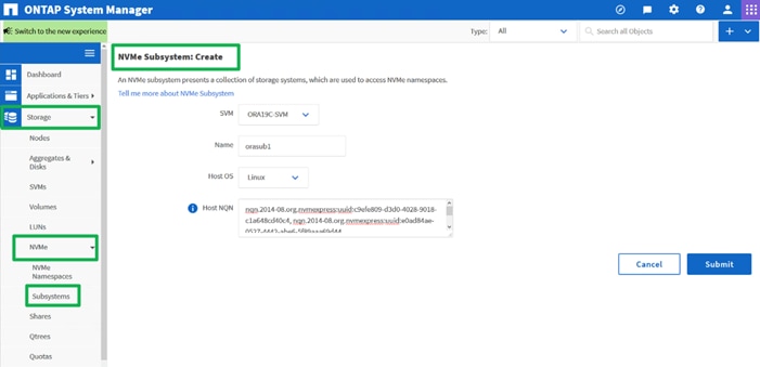
2. For this solution, configure four Subsystem on NVMe SVM “ORA19C-SVM” as “orasub1”, “orasub2”, “orasub3” and “orasub4”. On each of the subsystem, select Host OS as “Linux” and add all the eight-host unique “hostnqn” as shown below.
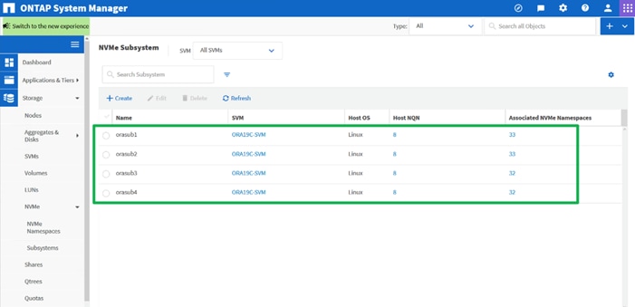
The overview of all the subsystems is shown below:
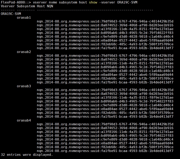
You will configure the NVMe Namespaces and associate them to these four subsystems later in the database creation section.
Discover Fabric Ports and Targets from OS
After configuring the storage NVMe Subsystem, connect the Linux hosts to NVMe Storage target as explained below.
![]() “fcc” is a tool that is packaged with the driver and can be used to list the FC HBAs and discovered remote ports and luns. Running the fcc without any arguments lists all FC (scsi) hosts, remote ports, and LUNs as sown below:
“fcc” is a tool that is packaged with the driver and can be used to list the FC HBAs and discovered remote ports and luns. Running the fcc without any arguments lists all FC (scsi) hosts, remote ports, and LUNs as sown below:
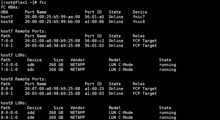
1. To list NVME hosts and NVME targets discovered by each host (FC-NVME only), run the following commands:
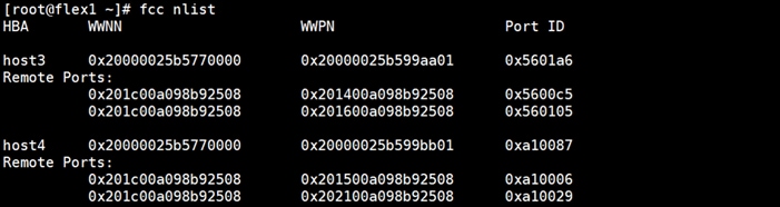
2. The FNIC driver automatically discovers and connects to NVME controllers. NVME storage controllers are automatically connected, and namespaces are discovered. User may also trigger manually to connect to NVME namespaces using “fcc connect all” command. If NVME storage connectivity changes during run-time, NVME controller discovery can also be manually triggered using “fcc discover all” command to discover any target changes. The following command can be used to check the available paths for an NVME sub system:
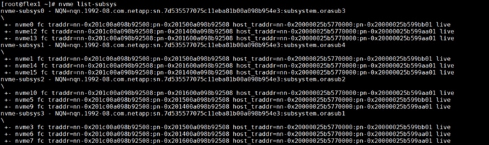
This concludes the NVMe/FC setup for the first Linux host. Repeat steps 1 and 2 on each remaining Linux hosts to enable and configure NVMe/FC storage connectivity.
Next, configure the operating system prerequisites to install Oracle Grid and Oracle Database Software as explained in the following sections.
This section describes how to optimize the BIOS settings to meet requirements for the best performance and energy efficiency for the Cisco UCS M5 generation of blade servers.
For more information about BIOS settings, refer to: https://www.cisco.com/c/dam/en/us/products/collateral/servers-unified-computing/ucs-b-series-blade-servers/whitepaper_c11-740098.pdf
![]() For this solution, we configured the BIOS settings as described in section Configure Server BIOS Policy. Apply these settings according to your environments.
For this solution, we configured the BIOS settings as described in section Configure Server BIOS Policy. Apply these settings according to your environments.
Disable C-States for OLTP Workloads
OLTP systems are often decentralized to avoid single points of failure. Spreading the work over multiple servers can also support greater transaction processing volume and reduce response time. Make sure to disable Intel IDLE driver in the OS configuration section. When Intel idle driver is disabled, the OS uses acpi_idle driver to control the C-States.
![]() For latency sensitive workloads, it is recommended to always disable c-states in both OS and BIOS to ensure c-states are disabled
For latency sensitive workloads, it is recommended to always disable c-states in both OS and BIOS to ensure c-states are disabled
If the CPU gets into a deeper C-state and not able to get out to deliver full performance quickly, then result is unwanted latency spikes for workloads. To address this, it is recommended to disable C states in the BIOS and in addition, Oracle recommends disabling it from OS level as well by modifying grub entries. To configure the BIOS options by modifying in the “/etc/default/grub” file, run the following commands:
[root@flex1 ~]$ cat /etc/default/grub
GRUB_TIMEOUT=5
GRUB_DISTRIBUTOR="$(sed 's, release .*$,,g' /etc/system-release)"
GRUB_DEFAULT=saved
GRUB_DISABLE_SUBMENU=true
GRUB_TERMINAL_OUTPUT="console"
GRUB_CMDLINE_LINUX="crashkernel=auto resume=/dev/mapper/ol-swap rd.lvm.lv=ol/root rd.lvm.lv=ol/swap rhgb quiet biosdevname=0 net.ifnames=0 nvme-core.multipath=Y numa=off transparent_hugepage=never intel_idle.max_cstate=0 processor.max_cstate=0"
GRUB_DISABLE_RECOVERY="true"
GRUB_ENABLE_BLSCFG=true
Configure OS Prerequisites for Oracle Software
To successfully install Oracle RAC Database 19c software, configure the operating system prerequisites on all eight nodes as explained in this section
![]() Follow the steps according to your environment and requirements. For more information, see the Install and Upgrade Guide for Linux for Oracle Database 19C: https://docs.oracle.com/en/database/oracle/oracle-database/19/cwlin/configuring-operating-systems-for-oracle-grid-infrastructure-on-linux.html#GUID-B8649E42-4918-49EA-A608-446F864EB7A0
Follow the steps according to your environment and requirements. For more information, see the Install and Upgrade Guide for Linux for Oracle Database 19C: https://docs.oracle.com/en/database/oracle/oracle-database/19/cwlin/configuring-operating-systems-for-oracle-grid-infrastructure-on-linux.html#GUID-B8649E42-4918-49EA-A608-446F864EB7A0
Prerequisites RPM Installation
To configure the operating system prerequisites using RPM for Oracle 19c software on all nodes, install the “oracle-database-preinstall-19c" rpm package. You can also download the required packages from http://public-yum.oracle.com/oracle-linux-7.html.
If you plan to use the “oracle-database-preinstall-19c" rpm package to perform all your prerequisite setup automatically, then login as root user and issue the following command on all the RAC nodes.
[root@orarac1 ~]# yum install oracle-database-preinstall-19c
![]() If you have not used the " oracle-database-preinstall-19c " package, then you will have to manually perform the prerequisites tasks on all the nodes.
If you have not used the " oracle-database-preinstall-19c " package, then you will have to manually perform the prerequisites tasks on all the nodes.
Additional Prerequisites Configuration
After configuring the automatic or manual prerequisites steps, you have to configure a few additional steps to complete the prerequisites for the Oracle database software installations on all eight nodes as described below.
Disable SELinux
As most of the Organizations might already be running hardware-based firewalls to protect their corporate networks, we disabled Security Enhanced Linux (SELinux) and the firewalls at the server level for this reference architecture.
You can set secure Linux to permissive by editing the "/etc/selinux/config" file, making sure the SELINUX flag is set as follows:
SELINUX=permissive
Disable Firewall
Check the status of the firewall by running following commands. (The status displays as active (running) or inactive (dead)). If the firewall is active / running, enter this command below to stop it:
systemctl status firewalld.service
systemctl stop firewalld.service
Also, to completely disable the firewalld service, so it does not reload when you restart the host machine, run the following command:
systemctl disable firewalld.service
Create the Grid User
Run this command to create a grid user:
useradd –u 54322 –g oinstall –G dba grid
Set the User Passwords
Run these commands to change the password for Oracle and Grid Users:
passwd oracle
passwd grid
Configure Multipath
For this solution, configure the DM-Multipath only for the FC Boot LUNs. For the NVMe/FC Storage path, you need to configure the native multipathing as explained previously.
![]() You must configure “enable_foreign” in “/etc/multipath.conf” for dm-multipath to prevent dm-multipath from claiming NVMe/FC namespace devices. We recommend you use in-kernel NVMe multipath for ONTAP namespaces and dm-multipath for ONTAP LUNs.
You must configure “enable_foreign” in “/etc/multipath.conf” for dm-multipath to prevent dm-multipath from claiming NVMe/FC namespace devices. We recommend you use in-kernel NVMe multipath for ONTAP namespaces and dm-multipath for ONTAP LUNs.
![]() For DM-Multipath Configuration and best practice, refer to NetApp Support: https://library.netapp.com/ecmdocs/ECMP1217221/html/GUID-34FA2578-0A83-4ED3-B4B3-8401703D65A6.html
For DM-Multipath Configuration and best practice, refer to NetApp Support: https://library.netapp.com/ecmdocs/ECMP1217221/html/GUID-34FA2578-0A83-4ED3-B4B3-8401703D65A6.html
To configure multipath, follow these steps:
1. Add or modify the /etc/multipath.conf file accordingly to provide the alias name of each LUN id presented from NetApp Storage as shown below into all 8 nodes:

2. Run multipath –ll command to view all the LUN IDs and enter that wwid information accordingly on each node:
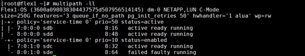
![]() Make sure the LUNs wwid address reflects the correct value for all eight nodes in “/etc/multipath.conf”. We made sure the multipathing packages were installed and enabled for automatic restart across reboots.
Make sure the LUNs wwid address reflects the correct value for all eight nodes in “/etc/multipath.conf”. We made sure the multipathing packages were installed and enabled for automatic restart across reboots.
Configure UDEV rules for IO Policy
You need to configure the UDEV rules to assign permission and IO Policy in all Oracle RAC nodes to access the NetApp Storage LUNs and Namespaces. This includes the device details along with required permissions to enable grid and oracle user to have read/write privileges on these devices.
To configure the UDEV rules on all Oracle RAC Nodes, follow this step:
1. Assign IO Policy by creating a new file named “71-nvme-iopolicy-netapp-ONTAP.rules” with the following entries on all the nodes:
[root@flex1 ~]# cat /etc/udev/rules.d/71-nvme-iopolicy-netapp-ONTAP.rules
### Enable round-robin for NetApp ONTAP
ACTION=="add", SUBSYSTEM=="nvme-subsystem", ATTR{model}=="NetApp ONTAP Controller", ATTR{iopolicy}="round-robin"
Configure /etc/hosts
To configure /etc/hosts, follow these steps:
1. Login as a root user into the node and edit the “/etc/hosts” file.
2. Provide the details for Public IP Address, Private IP Address, SCAN IP Address, and Virtual IP Address for all the nodes. Configure these settings in each Oracle RAC Nodes as shown below:
[root@flex1 ~]# cat /etc/hosts
127.0.0.1 localhost localhost.localdomain localhost4 localhost4.localdomain4
### Public IP ###
10.29.134.71 flex1 flex1.ciscoucs.com
10.29.134.72 flex2 flex2.ciscoucs.com
10.29.134.73 flex3 flex3.ciscoucs.com
10.29.134.74 flex4 flex4.ciscoucs.com
10.29.134.75 flex5 flex5.ciscoucs.com
10.29.134.76 flex6 flex6.ciscoucs.com
10.29.134.77 flex7 flex7.ciscoucs.com
10.29.134.78 flex8 flex8.ciscoucs.com
### Virtual IP ###
10.29.134.79 flex1-vip flex1-vip.ciscoucs.com
10.29.134.80 flex2-vip flex2-vip.ciscoucs.com
10.29.134.81 flex3-vip flex3-vip.ciscoucs.com
10.29.134.82 flex4-vip flex4-vip.ciscoucs.com
10.29.134.83 flex5-vip flex5-vip.ciscoucs.com
10.29.134.84 flex6-vip flex6-vip.ciscoucs.com
10.29.134.85 flex7-vip flex7-vip.ciscoucs.com
10.29.134.86 flex8-vip flex8-vip.ciscoucs.com
### Private IP ###
10.10.10.71 flex1-priv flex1-priv.ciscoucs.com
10.10.10.72 flex2-priv flex2-priv.ciscoucs.com
10.10.10.73 flex3-priv flex3-priv.ciscoucs.com
10.10.10.74 flex4-priv flex4-priv.ciscoucs.com
10.10.10.75 flex5-priv flex5-priv.ciscoucs.com
10.10.10.76 flex6-priv flex6-priv.ciscoucs.com
10.10.10.77 flex7-priv flex7-priv.ciscoucs.com
10.10.10.78 flex8-priv flex8-priv.ciscoucs.com
### SCAN IP ###
10.29.134.87 flex-scan flex-scan.ciscoucs.com
10.29.134.88 flex-scan flex-scan.ciscoucs.com
10.29.134.89 flex-scan flex-scan.ciscoucs.com
You must configure the following addresses manually in your corporate setup:
● A Public IP Address for each node
● A Virtual IP address for each node
● Three single client access name (SCAN) address for the oracle database cluster
All the steps above were performed on all of the eight nodes. These steps complete the prerequisite for Oracle Database 19c Installation at OS level on Oracle RAC Nodes.
Configure NetApp Storage Host Group and LUNs for OCR and Voting Disk
To create and configure the NVMe Namespaces for storing OCR and Cluster Files, follow these steps:
1. Login as Admin user into the NetApp array and go to Storage > NVMe > NVMe Namespaces > and click +Create.
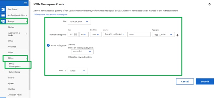
![]() For this solution, we created two namespaces. Namespace “asm1” was configured on “orasub1” and namespace “asm2” was configured on “orasub2” with each namespace was 100 GB in size as shown in above screenshot for storing OCR and Voting Disk files for all the RAC databases. Also, each namespace was spread across both the aggregate.
For this solution, we created two namespaces. Namespace “asm1” was configured on “orasub1” and namespace “asm2” was configured on “orasub2” with each namespace was 100 GB in size as shown in above screenshot for storing OCR and Voting Disk files for all the RAC databases. Also, each namespace was spread across both the aggregate.
2. When all the above O.S level prerequisites and namespaces are configured, install the Oracle Grid Infrastructure as a grid user. Download Oracle Database 19c Release (19.3) for Linux x86-64 and Oracle Database 19c Release Grid Infrastructure (19.3) for Linux x86-64 software from Oracle Software site. Copy these software binaries to Oracle RAC Node 1 and Unzip all files into appropriate directories.
These steps complete the prerequisite for Oracle Database 19c Installation at OS level on Oracle RAC Nodes.
Oracle Database 19c GRID Infrastructure Deployment
This section describes the high-level steps for the Oracle Database 19c RAC installation. This document provides a partial summary of details that might be relevant.
![]() It is not within the scope of this document to include the specifics of an Oracle RAC installation; you should refer to the Oracle installation documentation for specific installation instructions for your environment. For more information, use this link for Oracle Database 19c install and upgrade guide: https://docs.oracle.com/en/database/oracle/oracle-database/19/cwlin/index.html
It is not within the scope of this document to include the specifics of an Oracle RAC installation; you should refer to the Oracle installation documentation for specific installation instructions for your environment. For more information, use this link for Oracle Database 19c install and upgrade guide: https://docs.oracle.com/en/database/oracle/oracle-database/19/cwlin/index.html
For this solution, you will install the Oracle Grid and Database software on all the eight nodes (flex1 to flex8).
Oracle 19c Release 19.3 Grid Infrastructure (GI) was installed on the first node as a grid user. The installation also configured and added the remaining 7 nodes as a part of the GI setup. The Oracle Automatic Storage Management (ASM) in Flex mode was configured. Complete this procedure to install Oracle Grid Infrastructure software for Oracle Standalone Cluster.
![]() Download and copy the Oracle Grid Infrastructure image files to the local node only. During installation, the software is copied and installed on all other nodes in the cluster.
Download and copy the Oracle Grid Infrastructure image files to the local node only. During installation, the software is copied and installed on all other nodes in the cluster.
To create the directory structure appropriately according to your environment, run the following commands:
For example:
mkdir -p /u01/app/grid
mkdir -p /u01/app/19.3.0/grid
mkdir -p /u01/app/oraInventory
mkdir -p /u01/app/oracle/product/19.3.0/dbhome_1
chown -R grid:oinstall /u01/app/grid
chown -R grid:oinstall /u01/app/19.3.0/grid
chown -R grid:oinstall /u01/app/oraInventory
chown -R oracle:oinstall /u01/app/oracle
As the grid user, download the Oracle Grid Infrastructure image files and extract the files into the Grid home:
cd /u01/app/19.0.0/grid
unzip -q download_location/grid.zip
Configure UDEV rules for ASM Disks
You need to configure UDEV rules to have read/write privileges on these storage namespaces for grid user. This includes the device details and corresponding uuid of the storage namespaces.
Assign Owner and Permission on NVMe Targets by creating a new file named “80-nvme.rules” with the following entries on all the nodes:
[root@flex1 ~]# cat /etc/udev/rules.d/80-nvme.rules
# All ASM Volumes For GRID Users
KERNEL=="nvme[0-9]*n[0-9]*", ENV{DEVTYPE}=="disk", ENV{ID_WWN}=="uuid.7636791b-944f-4adb-941e-0d962639f718", SYMLINK+="asm1", GROUP:="oinstall", OWNER:="grid", MODE:="660"
KERNEL=="nvme[0-9]*n[0-9]*", ENV{DEVTYPE}=="disk", ENV{ID_WWN}=="uuid.1251e1c3-3735-4546-8b39-6654c83620f7", SYMLINK+="asm2", GROUP:="oinstall", OWNER:="grid", MODE:="660"
Run Cluster Verification Utility
This step verifies that all the prerequisites are met to install the Oracle Grid Infrastructure Software. Oracle Grid Infrastructure ships with the Cluster Verification Utility (CVU) that can run to validate the pre and post installation configurations.
To run this utility, login as Grid User in Oracle RAC Node 1 and go to the directory where oracle grid software binaries are located. Run script named as “runcluvfy.sh” as follows:
./runcluvfy.sh stage -pre crsinst -n flex1,flex2,flex3,flex4,flex5,flex6,flex7,flex8 –verbose
HugePages is a method to have larger page size that is useful for working with a very large memory. For Oracle Databases, using HugePages reduces the operating system maintenance of page states, and increases Translation Lookaside Buffer (TLB) hit ratio.
Advantage of HugePages:
● HugePages are not swappable so there is no page-in/page-out mechanism overhead.
● HugePages uses fewer pages to cover the physical address space, so the size of "bookkeeping"(mapping from the virtual to the physical address) decreases, so it is requiring fewer entries in the TLB and so TLB hit ratio improves.
● HugePages reduces page table overhead. Also, HugePages eliminated page table lookup overhead: Since the pages are not subject to replacement, page table lookups are not required.
● Faster overall memory performance: On virtual memory systems each memory operation is two abstract memory operations. Since there are fewer pages to work on, the possible bottleneck on page table access is clearly avoided.
For our configuration, we used HugePages for all the OLTP and DSS workloads. Please refer to the oracle guidelines to configure appropriately as below:
After configuration, you are ready to install the Oracle Grid Infrastructure and Oracle Database 19c software. For this solution, we installed Oracle home binaries on the boot LUN of the nodes. The OCR, Data, and Redo Log files reside in the namespace configured on netapp storage array.
Install and Configure Oracle Database Grid Infrastructure Software
![]() It is not within the scope of this document to include the specifics of an Oracle RAC installation. However, a partial summary of details is provided that might be relevant. Please refer to the Oracle installation documentation for specific installation instructions for your environment.
It is not within the scope of this document to include the specifics of an Oracle RAC installation. However, a partial summary of details is provided that might be relevant. Please refer to the Oracle installation documentation for specific installation instructions for your environment.
To install Oracle Database Grid Infrastructure Software, follow these steps:
1. Go to grid home where the Oracle 19c Grid Infrastructure software binaries are located and launch the installer as the "grid" user.
2. Start the Oracle Grid Infrastructure installer by running the following command:
./gridSetup.sh
3. Select option “Configure Oracle Grid Infrastructure for a New Cluster”, then click Next.
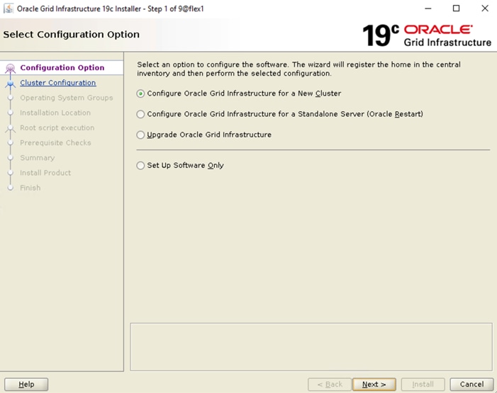
4. Select cluster configuration options “Configure an Oracle Standalone Cluster”, then click Next
5. In next window, enter the Cluster Name and SCAN Name fields. Enter the names for your cluster and cluster scan that are unique throughout your entire enterprise network. You can also select to Configure GNS if you have configured your domain name server (DNS) to send to the GNS virtual IP address name resolution requests.
6. In Cluster node information window, click the "Add" button to add all the eight nodes Public Hostname and Virtual Hostname as shown below:
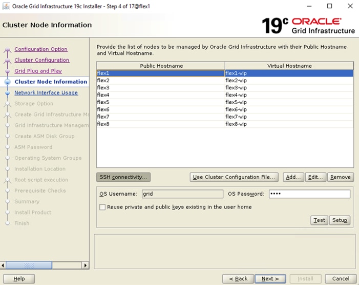
7. As shown above, you will see all nodes listed in the table of cluster nodes. Click the SSH Connectivity button at the bottom of the window. Enter the operating system username and password for the Oracle software owner (grid). Click Setup.
8. A message window appears, indicating that it might take several minutes to configure SSH connectivity between the nodes. After some time, another message window appears indicating that password-less SSH connectivity has been established between the cluster nodes. Click OK to continue
9. In Network Interface Usage screen, select the usage type for each network interface displayed as shown below:
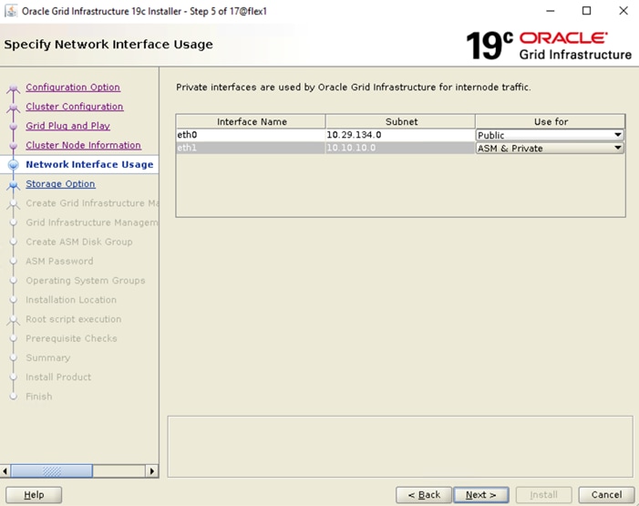
10. In storage option, Select the option as “Use Oracle Flex ASM for storage” then click on “Next”. For this solution we have choose “No” option into separate ASM disk group for the Grid Infrastructure Management Repository data.
11. In the Create ASM Disk Group window, select the “ASM1” & “ASM2” namespaces which are configured into NetApp Storage to store OCR and Voting disk files. Enter the name of disk group as “OCRVOTE” and select appropriate external redundancy options as shown below:
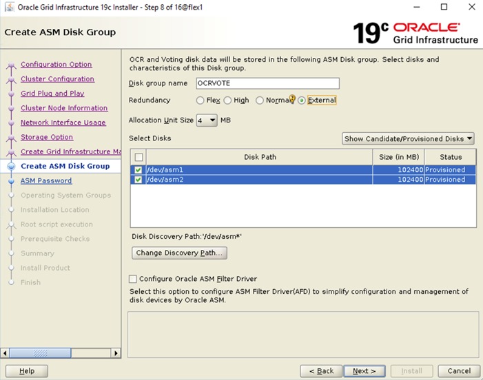
![]() For this solution, we did not configure Oracle ASM Filter Driver.
For this solution, we did not configure Oracle ASM Filter Driver.
12. Choose the password for the Oracle ASM SYS and ASMSNMP account, then click Next.
13. Select the option “Do not use Intelligent Platform Management Interface (IPMI)”. Click Next.
14. You can configure to have this instance of Oracle Grid Infrastructure and Oracle Automatic Storage Management to be managed by Enterprise Manager Cloud Control. For this solution we did not select this option. Click Next.
![]() You can choose to set it up according to your requirements.
You can choose to set it up according to your requirements.
15. Select the appropriate operating system group names for Oracle ASM according to your environments.
16. Specify the oracle base and inventory directory to use for the Oracle Grid Infrastructure installation and then click Next. The Oracle base directory must be different from the Oracle home directory. Click Next and choose Inventory Directory according to your setup.
17. Click Automatically run configuration scripts to run scripts automatically and enter the relevant root user credentials. Click Next.
18. Wait while the prerequisite checks complete. If you have any issues, click the "Fix & Check Again" button. If any of the checks have a status of Failed and are not fixable, then you must manually correct these issues. After you have fixed the issue, you can click the Check Again button to have the installer re-check the requirement and update the status. Repeat as needed until all the checks have a status of Succeeded. Click Next.
19. Review the contents of the Summary window and then click Install. The installer displays a progress indicator enabling you to monitor the installation process.
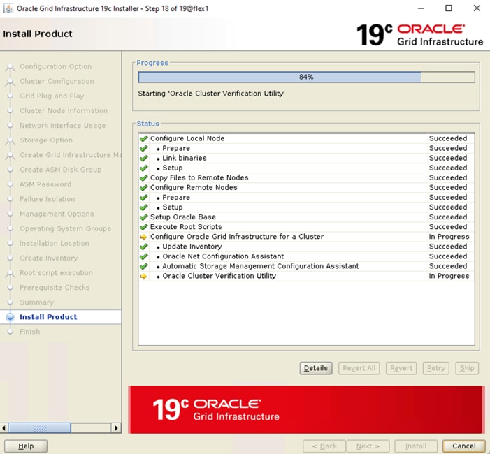
20. Wait for the grid installer configuration assistants to complete.
21. When the configuration complete successfully, click Close to finish and exit the grid installer.
22. When GRID install is successful, login to each of the nodes and perform minimum health checks to make sure that Cluster state is healthy. After your Oracle Grid Infrastructure installation is complete, you can install Oracle Database on a cluster node for high availability or install Oracle RAC.
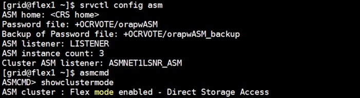
After successful Oracle GRID software install, we recommend installing Oracle Database 19c software only. You can create databases using DBCA or database creation scripts at later stage.
![]() It is not within the scope of this document to include the specifics of an Oracle RAC database installation. However, we will provide partial summary of details that might be relevant. Please refer to the Oracle database installation documentation for specific installation instructions for your environment. https://docs.oracle.com/en/database/oracle/oracle-database/19/ladbi/index.html
It is not within the scope of this document to include the specifics of an Oracle RAC database installation. However, we will provide partial summary of details that might be relevant. Please refer to the Oracle database installation documentation for specific installation instructions for your environment. https://docs.oracle.com/en/database/oracle/oracle-database/19/ladbi/index.html
To install Oracle Database software, follow these steps:
1. Start the “./runInstaller” command from the Oracle Database 19c installation media where Oracle database software is located.
2. Select option “Set Up Software Only” into configuration Option.
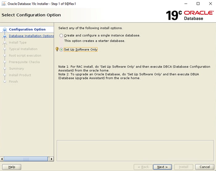
3. Select option "Oracle Real Application Clusters database installation" and click Next.
4. Select nodes in the cluster where installer should install Oracle RAC. For this setup, install the software on all eight nodes as shown below:
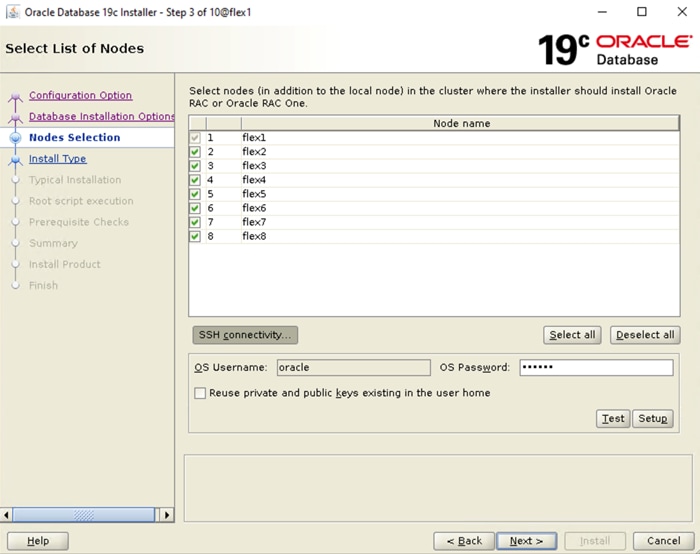
5. Click "SSH Connectivity..." and enter the password for the "oracle" user. Click Setup to configure passwordless SSH connectivity and click Test to test it when it is complete. When the test is complete, click Next.
6. Select Database Edition Options according to your environments and then click Next.
7. Enter appropriate Oracle Base, then click Next.
8. Select the desired operating system groups and then click Next.
9. Select option Automatically run configuration script from the option Root script execution menu and click Next.
10. Wait for the prerequisite check to complete. If there are any problems click "Fix & Check Again" or try to fix those by checking and manually installing required packages. Click Next.
11. Verify the Oracle Database summary information and then click Install.
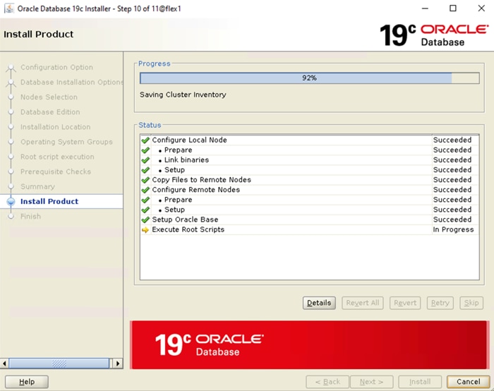
12. Wait for the installation of Oracle Database finish successfully, then click Close to exit of the installer.
Oracle ASM is Oracle's recommended storage management solution that provides an alternative to conventional volume managers, file systems, and raw devices. Oracle ASM is a volume manager and a file system for Oracle Database files that reduces the administrative overhead for managing database storage by consolidating data storage into a small number of disk groups. The smaller number of disk groups consolidates the storage for multiple databases and provides for improved I/O performance.
Oracle Flex ASM enables an Oracle ASM instance to run on a separate physical server from the database servers. With this deployment, larger clusters of Oracle ASM instances can support more database clients while reducing the Oracle ASM footprint for the overall system.
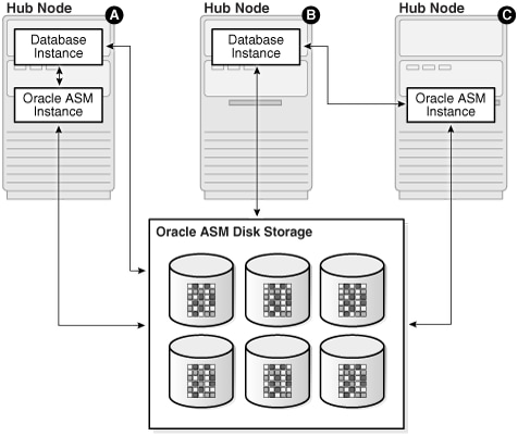
When using Oracle Flex ASM, Oracle ASM clients are configured with direct access to storage. With Oracle Flex ASM, you can consolidate all the storage requirements into a single set of disk groups. All these disk groups are mounted by and managed by a small set of Oracle ASM instances running in a single cluster. You can specify the number of Oracle ASM instances with a cardinality setting. The default is three instances.
Prior to Oracle 12c, if ASM instance on one of the RAC nodes crashes, all the instances running on that node will crash too. This issue has been addressed in Flex ASM; Flex ASM can be used even if all the nodes are hub nodes. However, GNS configuration is mandatory for enabling Flex ASM. You can check what instances relate to a simple query as shown below:
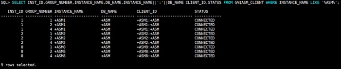
As you can see from the query (above), instance1 (FLEX1), instance2 (FLEX2) and instance8 (FLEX8) are connected to +ASM. There are a few more commands you can run to check cluster and FLEX ASM details as shown below:
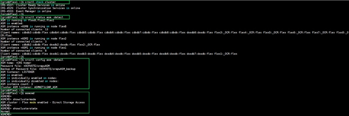
Refer to the Oracle documentation for more information: https://docs.oracle.com/en/database/oracle/oracle-database/19/ostmg/manage-flex-asm.html#GUID-DE759521-9CF3-45D9-9123-7159C9ED4D30
Oracle Database Multitenant Architecture
The multitenant architecture enables an Oracle database to function as a multitenant container database (CDB). A CDB includes zero, one, or many customer-created pluggable databases (PDBs). A PDB is a portable collection of schemas, schema objects, and non-schema objects that appears to an Oracle Net client as a non-CDB. All Oracle databases before Oracle Database 12c were non-CDBs.
A container is logical collection of data or metadata within the multitenant architecture. The following figure represents possible containers in a CDB.
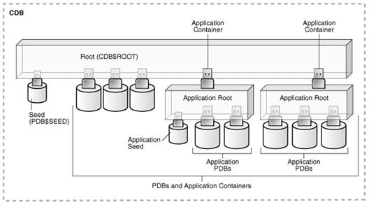
The multitenant architecture solves several problems posed by the traditional non-CDB architecture. Large enterprises may use hundreds or thousands of databases. Often these databases run on different platforms on multiple physical servers. Because of improvements in hardware technology, especially the increase in the number of CPUs, servers can handle heavier workloads than before. A database may use only a fraction of the server hardware capacity. This approach wastes both hardware and human resources. Database consolidation is the process of consolidating data from multiple databases into one database on one computer. The Oracle Multitenant option enables you to consolidate data and code without altering existing schemas or applications.
For more information on Oracle Database Multitenant Architecture, please refer to: https://docs.oracle.com/en/database/oracle/oracle-database/19/multi/introduction-to-the-multitenant-architecture.html#GUID-267F7D12-D33F-4AC9-AA45-E9CD671B6F22
![]() In this solution, we configured both type of databases to check performance of Non-Container Databases and Container Databases as explained in the next scalability test section.
In this solution, we configured both type of databases to check performance of Non-Container Databases and Container Databases as explained in the next scalability test section.
Before configuring a database for workload tests, it is extremely important to validate that this is indeed a balanced configuration that is capable of delivering expected performance. In this solution, we will test and validate node and user scalability on all 8 node Oracle RAC Databases with various database benchmarking tools as explained below.
Hardware Calibration Test using FIO
FIO is short for Flexible IO, a versatile IO workload generator. FIO is a tool that will spawn a number of threads or processes doing a particular type of I/O action as specified by the user. For our solution, we use FIO to measure the performance of a NetApp storage device over a given period of time. For the FIO Tests, we created 4 Subsystems with total 32 Namespaces (each subsystem having 8 Namespaces) and each of the subsystem was 500 GB in size equally distributed across both the aggregates. These 32 Namespace were shared across all the eight nodes for read/write IO operations.
We run various FIO tests for measuring IOPS, Latency and Throughput performance of this solution by changing block size parameter into the FIO test. For each FIO test, we also changed read/write ratio as 0/100% read/write, 50/50% read/write, 70/30% read/write, 90/10% read/write and 100/0% read/write to scale the performance of the system. We also ran the tests for at least 4 hours to help ensure that this configuration is capable of sustaining this type of load for longer period of time.
The chart below shows results for the random read/write FIO test for the 8k block size representing OLTP type of workloads.
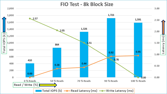
For the 100/0% read/write test, we achieved around 1591k IOPS with the read latency around 0.95 millisecond. Similarly, for the 90/10% read/write test, we achieved around 1723k IOPS with the read latency around 0.92 millisecond and the write latency around 0.78 millisecond. For the 70/30% read/write test, we achieved around 1326k IOPS with the read latency around 0.44 millisecond and the write latency around 1.5 millisecond. For the 50/50% read/write test, we achieved around 864k IOPS with the read latency around 0.38 millisecond and the write latency around 2.05 millisecond. For the 0/100% read/write test, we achieved around 410k IOPS with the write latency around 2.57 millisecond. Reads and writes consume system resources differently. The system under test benefited from slightly better resource distribution in the 90/10 R/W test, resulting in slightly improved peak IOPS in this test compared with the 100/0 R/W test
The bandwidth tests are carried out with 512k IO Size and represents the DSS database type workloads. The chart below shows results for the sequential read/write FIO test for the 512k block size.
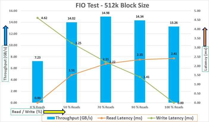
For the 100/0% read/write test, we achieved around 13.26 GB/s throughput with the read latency around 2.4 millisecond. Similarly, for the 90/10% read/write test, we achieved around 14.34 GB/s throughput with the read latency around 2.3 millisecond and the write latency around 1.4 millisecond. For the 70/30% read/write test, we achieved around 14.98 GB/s throughput with the read latency around 2.1 millisecond and the write latency around 2.2 millisecond. For the 50/50% read/write test, we achieved around 14 GB/s throughput with the read latency around 1.5 millisecond and the write latency around 3.25 millisecond. For the 0/100% read/write test, we achieved around 7.2 GB/s throughput with the write latency around 4.6 millisecond.
We did not see any performance dips or degradation over the period of run time. It is also important to note that this is not a benchmarking exercise, and these are practical and out of box test numbers that can be easily reproduced by anyone. At this time, we are ready to create OLTP database(s) and continue with database tests.
We used Oracle Database Configuration Assistant (DBCA) to create three OLTP (SLOB, SOEPDB and SOEFIN) and one DSS (PDBSH) databases for SLOB and SwingBench test calibration. Alternatively, you can use Database creation scripts to create the databases as well.
For all the database deployment, we have configured two aggregates (one aggregate on each storage node) into a single SVM, and each aggregate contains 11 SSD (1.75 TB Each) drives that were subdivided into RAID DP groups, plus one spare drive as explained earlier in the storage configuration section.
For each RAC database, we created total number of 32 Namespaces. We distributed equal number of namespaces on the storage nodes by placing those namespaces into both the aggregates. All the database files were also spread evenly across the two nodes of the storage system so that each storage node served data for the databases. Table 11 lists the storage layout of all the namespaces configuration for all the databases.
Table 11. Namespace Storage Layout
| Database Name |
Subsystem |
Namespace |
Size (GB) |
Aggregate |
Notes |
| ASM |
orasub1 |
asm1 |
100 |
aggr1_node1 |
OCR & Voting Disk |
| orasub2 |
asm2 |
100 |
aggr1_node2 |
||
| SLOB (Non CDB Database) |
orasub1 |
dataslob01 |
300 |
aggr1_node1 |
SLOB Database Data Files |
| orasub2 |
dataslob02 |
300 |
aggr1_node1 |
||
| orasub3 |
dataslob03 |
300 |
aggr1_node1 |
||
| orasub4 |
dataslob04 |
300 |
aggr1_node1 |
||
| orasub1 |
dataslob05 |
300 |
aggr1_node2 |
||
| orasub2 |
dataslob06 |
300 |
aggr1_node2 |
||
| orasub3 |
dataslob07 |
300 |
aggr1_node2 |
||
| orasub4 |
dataslob08 |
300 |
aggr1_node2 |
||
| orasub1 |
dataslob09 |
300 |
aggr1_node1 |
||
| orasub2 |
dataslob10 |
300 |
aggr1_node1 |
||
| orasub3 |
dataslob11 |
300 |
aggr1_node1 |
||
| orasub4 |
dataslob12 |
300 |
aggr1_node1 |
||
| orasub1 |
dataslob13 |
300 |
aggr1_node2 |
||
| orasub2 |
dataslob14 |
300 |
aggr1_node2 |
||
| orasub3 |
dataslob15 |
300 |
aggr1_node2 |
||
| orasub4 |
dataslob16 |
300 |
aggr1_node2 |
||
| orasub1 |
dataslob17 |
300 |
aggr1_node1 |
||
| orasub2 |
dataslob18 |
300 |
aggr1_node1 |
||
| orasub3 |
dataslob19 |
300 |
aggr1_node1 |
||
| orasub4 |
dataslob20 |
300 |
aggr1_node1 |
||
| orasub1 |
dataslob21 |
300 |
aggr1_node2 |
||
| orasub2 |
dataslob22 |
300 |
aggr1_node2 |
||
| orasub3 |
dataslob23 |
300 |
aggr1_node2 |
||
| orasub4 |
dataslob24 |
300 |
aggr1_node2 |
||
| orasub1 |
redoslob01 |
50 |
aggr1_node1 |
SLOB Database Redo Log Files |
|
| orasub2 |
redoslob02 |
50 |
aggr1_node1 |
||
| orasub3 |
redoslob03 |
50 |
aggr1_node1 |
||
| orasub4 |
redoslob04 |
50 |
aggr1_node1 |
||
| orasub1 |
redoslob05 |
50 |
aggr1_node2 |
||
| orasub2 |
redoslob06 |
50 |
aggr1_node2 |
||
| orasub3 |
redoslob07 |
50 |
aggr1_node2 |
||
| orasub4 |
redoslob08 |
50 |
aggr1_node2 |
||
| CDBDB (Container Database) |
orasub1 |
datacdb01 |
200 |
aggr1_node1 |
CDBDB Database Data Files |
| orasub2 |
datacdb02 |
200 |
aggr1_node2 |
||
| orasub3 |
datacdb03 |
200 |
aggr1_node1 |
||
| orasub4 |
datacdb04 |
200 |
aggr1_node2 |
||
| orasub1 |
redocdb01 |
50 |
aggr1_node1 |
CDBDB Database Redo Log Files |
|
| orasub2 |
redocdb02 |
50 |
aggr1_node1 |
||
| orasub3 |
redocdb03 |
50 |
aggr1_node1 |
||
| orasub4 |
redocdb04 |
50 |
aggr1_node1 |
||
| orasub1 |
redocdb05 |
50 |
aggr1_node2 |
||
| orasub2 |
redocdb06 |
50 |
aggr1_node2 |
||
| orasub3 |
redocdb07 |
50 |
aggr1_node2 |
||
| orasub4 |
redocdb08 |
50 |
aggr1_node2 |
||
| PDBSOE (Pluggable Database on Container CDBDB Database) |
orasub1 |
pdbsoe01 |
400 |
aggr1_node1 |
PDBSOE Database Data Files |
| orasub2 |
pdbsoe02 |
400 |
aggr1_node1 |
||
| orasub3 |
pdbsoe03 |
400 |
aggr1_node1 |
||
| orasub4 |
pdbsoe04 |
400 |
aggr1_node1 |
||
| orasub1 |
pdbsoe05 |
400 |
aggr1_node2 |
||
| orasub2 |
pdbsoe06 |
400 |
aggr1_node2 |
||
| orasub3 |
pdbsoe07 |
400 |
aggr1_node2 |
||
| orasub4 |
pdbsoe08 |
400 |
aggr1_node2 |
||
| orasub1 |
pdbsoe09 |
400 |
aggr1_node1 |
||
| orasub2 |
pdbsoe10 |
400 |
aggr1_node1 |
||
| orasub3 |
pdbsoe11 |
400 |
aggr1_node1 |
||
| orasub4 |
pdbsoe12 |
400 |
aggr1_node1 |
||
| orasub1 |
pdbsoe13 |
400 |
aggr1_node2 |
||
| orasub2 |
pdbsoe14 |
400 |
aggr1_node2 |
||
| orasub3 |
pdbsoe15 |
400 |
aggr1_node2 |
||
| orasub4 |
pdbsoe16 |
400 |
aggr1_node2 |
||
| orasub1 |
pdbsoe17 |
400 |
aggr1_node1 |
||
| orasub2 |
pdbsoe18 |
400 |
aggr1_node1 |
||
| orasub3 |
pdbsoe19 |
400 |
aggr1_node1 |
||
| orasub4 |
pdbsoe20 |
400 |
aggr1_node1 |
||
| orasub1 |
pdbsoe21 |
400 |
aggr1_node2 |
||
| orasub2 |
pdbsoe22 |
400 |
aggr1_node2 |
||
| orasub3 |
pdbsoe23 |
400 |
aggr1_node2 |
||
| orasub4 |
pdbsoe24 |
400 |
aggr1_node2 |
||
| PDBFIN (Pluggable Database on Container CDBDB Database) |
orasub1 |
pdbfin01 |
300 |
aggr1_node1 |
PDBFIN Database Data Files |
| orasub2 |
pdbfin02 |
300 |
aggr1_node1 |
||
| orasub3 |
pdbfin03 |
300 |
aggr1_node1 |
||
| orasub4 |
pdbfin04 |
300 |
aggr1_node1 |
||
| orasub1 |
pdbfin05 |
300 |
aggr1_node2 |
||
| orasub2 |
pdbfin06 |
300 |
aggr1_node2 |
||
| orasub3 |
pdbfin07 |
300 |
aggr1_node2 |
||
| orasub4 |
pdbfin08 |
300 |
aggr1_node2 |
||
| orasub1 |
pdbfin09 |
300 |
aggr1_node1 |
||
| orasub2 |
pdbfin10 |
300 |
aggr1_node1 |
||
| orasub3 |
pdbfin11 |
300 |
aggr1_node1 |
||
| orasub4 |
pdbfin12 |
300 |
aggr1_node1 |
||
| orasub1 |
pdbfin13 |
300 |
aggr1_node2 |
||
| orasub2 |
pdbfin14 |
300 |
aggr1_node2 |
||
| orasub3 |
pdbfin15 |
300 |
aggr1_node2 |
||
| orasub4 |
pdbfin16 |
300 |
aggr1_node2 |
||
| orasub1 |
pdbfin17 |
300 |
aggr1_node1 |
||
| orasub2 |
pdbfin18 |
300 |
aggr1_node1 |
||
| orasub3 |
pdbfin19 |
300 |
aggr1_node1 |
||
| orasub4 |
pdbfin20 |
300 |
aggr1_node1 |
||
| orasub1 |
pdbfin21 |
300 |
aggr1_node2 |
||
| orasub2 |
pdbfin22 |
300 |
aggr1_node2 |
||
| orasub3 |
pdbfin23 |
300 |
aggr1_node2 |
||
| orasub4 |
pdbfin24 |
300 |
aggr1_node2 |
||
| DSSDB (Container Database) |
orasub1 |
datadss01 |
200 |
aggr1_node1 |
DSSDB Database Data Files |
| orasub2 |
datadss02 |
200 |
aggr1_node2 |
||
| orasub3 |
datadss03 |
200 |
aggr1_node1 |
||
| orasub4 |
datadss04 |
200 |
aggr1_node2 |
||
| orasub1 |
redodss01 |
50 |
aggr1_node1 |
DSSDB Database Redo Log Files |
|
| orasub2 |
redodss02 |
50 |
aggr1_node1 |
||
| orasub3 |
redodss03 |
50 |
aggr1_node1 |
||
| orasub4 |
redodss04 |
50 |
aggr1_node1 |
||
| orasub1 |
redodss05 |
50 |
aggr1_node2 |
||
| orasub2 |
redodss06 |
50 |
aggr1_node2 |
||
| orasub3 |
redodss07 |
50 |
aggr1_node2 |
||
| orasub4 |
redodss08 |
50 |
aggr1_node2 |
||
| PDBSH (Pluggable Database on Container DSSDB Database) |
orasub1 |
pdbsh01 |
400 |
aggr1_node1 |
PDBSH Database Data Files |
| orasub2 |
pdbsh02 |
400 |
aggr1_node1 |
||
| orasub3 |
pdbsh03 |
400 |
aggr1_node1 |
||
| orasub4 |
pdbsh04 |
400 |
aggr1_node1 |
||
| orasub1 |
pdbsh05 |
400 |
aggr1_node2 |
||
| orasub2 |
pdbsh06 |
400 |
aggr1_node2 |
||
| orasub3 |
pdbsh07 |
400 |
aggr1_node2 |
||
| orasub4 |
pdbsh08 |
400 |
aggr1_node2 |
||
| orasub1 |
pdbsh09 |
400 |
aggr1_node1 |
||
| orasub2 |
pdbsh10 |
400 |
aggr1_node1 |
||
| orasub3 |
pdbsh11 |
400 |
aggr1_node1 |
||
| orasub4 |
pdbsh12 |
400 |
aggr1_node1 |
||
| orasub1 |
pdbsh13 |
400 |
aggr1_node2 |
||
| orasub2 |
pdbsh14 |
400 |
aggr1_node2 |
||
| orasub3 |
pdbsh15 |
400 |
aggr1_node2 |
||
| orasub4 |
pdbsh16 |
400 |
aggr1_node2 |
||
| orasub1 |
pdbsh17 |
400 |
aggr1_node1 |
||
| orasub2 |
pdbsh18 |
400 |
aggr1_node1 |
||
| orasub3 |
pdbsh19 |
400 |
aggr1_node1 |
||
| orasub4 |
pdbsh20 |
400 |
aggr1_node1 |
||
| orasub1 |
pdbsh21 |
400 |
aggr1_node2 |
||
| orasub2 |
pdbsh22 |
400 |
aggr1_node2 |
||
| orasub3 |
pdbsh23 |
400 |
aggr1_node2 |
||
| orasub4 |
pdbsh24 |
400 |
aggr1_node2 |
As shown in Table 11, each database has a total 32 namespaces. On these 32 namespaces, two disk groups were created to store the “data” and “redolog” files for the database. 24 namespaces were used to create Oracle ASM “Data” disk group and 8 namespaces to create Oracle ASM “redolog” disk group for each database. We have used widely adopted SLOB and Swingbench database performance test tools to test and validate throughput, IOPS, and latency for various test scenarios as explained below.
The Silly Little Oracle Benchmark (SLOB) is a toolkit for generating and testing I/O through an Oracle database. SLOB is very effective in testing the I/O subsystem with genuine Oracle SGA-buffered physical I/O. SLOB supports testing physical random single-block reads (db file sequential read) and random single block writes (DBWR flushing capability). SLOB issues single block reads for the read workload that are generally 8K (as the database block size was 8K).
For testing the SLOB workload, we created one non-container database as SLOB. For SLOB database, we created total 32 namespace. On these 32 namespaces, we created two disk groups to store the “data” and “redolog” files for the SLOB database. First disk-group “DATASLOB” was created with 24 namespaces (300 GB each) while second disk-group “REDOSLOB” was created with 8 namespaces (50 GB each).
Those ASM disk groups provided the storage required to create the tablespaces for the SLOB Database. We loaded SLOB schema on “DATASLOB” disk-group of up to 3.5 TB in size.
We used SLOB2 to generate our OLTP workload. Each database server applied the workload to Oracle database, log, and temp files. The following tests were performed and various metrics like IOPS and latency were captured along with Oracle AWR reports for each test scenario.
SLOB2 was configured to run against all the eight Oracle RAC nodes and the concurrent users were equally spread across all the nodes. We tested the environment by increasing the number of Oracle users in database from a minimum of 64 users up to a maximum of 512 users across all the nodes. At each load point, we verified that the storage system and the server nodes could maintain steady-state behavior without any issues. We also made sure that there were no bottlenecks across servers or networking systems.
The User Scalability test was performed with 64, 128, 192, 256, 384 and 512 users on 8 Oracle RAC nodes by varying read/write ratio as explained below:
● Varying workloads
◦ 100% read (0% update)
◦ 90% read (10% update)
◦ 70% read (30% update)
◦ 50% read (50% update)
Table 12 lists the total number of IOPS (both read and write) available for user scalability test when run with 64, 128, 192, 256, 384 and 512 Users on the SLOB database.
Table 12. Total IOPS for SLOB User Scalability Tests
| Users |
Read/Write % (100-0) |
Read/Write % (90-10) |
Read/Write % (70-30) |
Read/Write % (50-50) |
| 64 |
388,706 |
405,485 |
457,021 |
488,826 |
| 128 |
736,713 |
763,770 |
746,430 |
756,207 |
| 192 |
989,616 |
1,047,593 |
1,018,685 |
898,215 |
| 256 |
1,227,841 |
1,264,029 |
1,090,525 |
938,379 |
| 384 |
1,457,965 |
1,493,350 |
1,128,892 |
965,426 |
| 512 |
1,544,274 |
1,579,193 |
1,156,161 |
959,938 |
The following graphs demonstrate the total number of IOPS while running SLOB workload for various concurrent users for each test scenario.
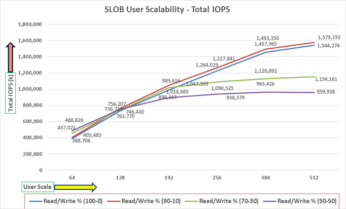
The graph above shows the linear scalability with increased users and similar IOPS from 64 users to 512 users with 100% Read/Write, 90% Read/Write, 70% Read/Write and 50% Read/Write.
The AWR screenshot shown below was captured from a 100% Read (0% update) Test scenario while running SLOB test for 512 users. The screenshot shows a section from the Oracle AWR report from the run that highlights Physical Reads/Sec and Physical Writes/Sec for each instance.
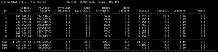
The screenshot above highlights that IO load is distributed across all the cluster nodes performing workload operations. Due to variations in workload randomness, we conducted multiple runs to ensure consistency in behavior and test results.
The screenshot shown below was captured from a 70% Read (30% update) Test scenario while running SLOB test for 512 users. The snapshot shows a section from AWR report from the run that highlights Physical Reads/Sec and Physical Writes/Sec for each instance.
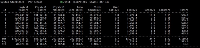
The following graph illustrates the latency exhibited by the NetApp AFF A800 Storage across different workloads. All the workloads experienced less than 1 millisecond latency and it varies based on the workloads. As expected, the 50% read (50% update) test exhibited higher latencies as the user counts increases.
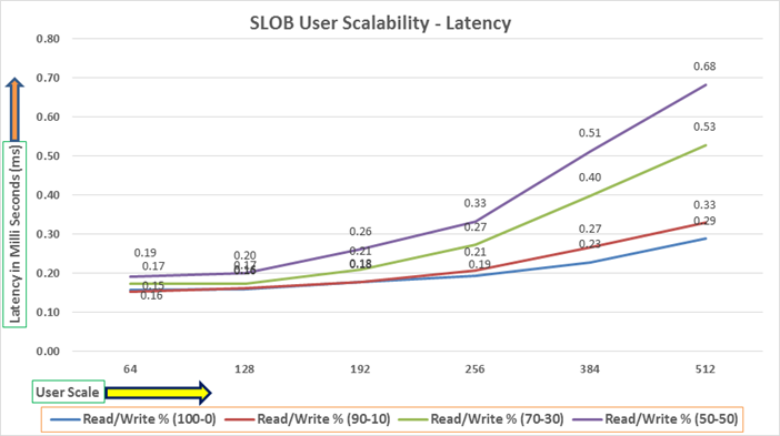
The following screenshot was captured from 100 % Read (0% Update) Test scenario while running SLOB test for 512 users. The snapshot shows a section of AWR report from the run that highlights top timed Events.
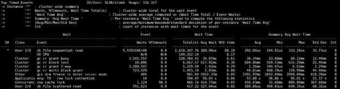
Swingbench is a simple to use, free, Java-based tool to generate various type of database workloads and perform stress testing using different benchmarks in Oracle database environments. Swingbench can be used to demonstrate and test technologies such as Real Application Clusters, Online table rebuilds, Standby databases, online backup, and recovery, etc. In this solution, we have used Swingbench tool for running various type of workload and check the overall performance of this reference architecture.
Swingbench provides four separate benchmarks, namely, Order Entry, Sales History, Calling Circle, and Stress Test. For the tests described in this solution, Swingbench Order Entry (SOE) benchmark was used for representing OLTP type of workload and the Sales History (SH) benchmark was used for representing DSS type of workload.
The Order Entry benchmark is based on SOE schema and is TPC-C like by types of transactions. The workload uses a very balanced read/write ratio around 60/40 and can be designed to run continuously and test the performance of a typical Order Entry workload against a small set of tables, producing contention for database resources.
The Sales History benchmark is based on the SH schema and is like TPC-H. The workload is query (read) centric and is designed to test the performance of queries against large tables.
Typically encountered in the real-world deployments, we tested a combination of scalability and stress related scenarios that ran across all of the 8-node Oracle RAC cluster, as follows:
● OLTP database user scalability workload representing small and random transactions
● DSS database workload representing larger transactions
● Mixed databases (OLTP and DSS) workloads running simultaneously
For the Swingbench workload tests, we created two Container Database as “CDBDB” and “DSSDB”. We configured the “CDBDB” container database and created two Pluggable Databases as “PDBSOE” and “PDBFIN” to run the Swingbench SOE workload representing OLTP type of workload characteristics. We configured the “DSSDB” container databases and created one Pluggable Databases as “PDBSH” to run the Swingbench SH workload representing DSS type of workload characteristics.
For this solution, we deployed multiple pluggable databases (PDBSOE and PDBFIN) plugged into one container (CDBDB) database and one pluggable database (PDBSH) plugged into one container (DSSDB) database to demonstrate the multitenancy capability, performance, and sustainability for this reference architecture.
In “CDBDB” container database, we created two pluggable databases as both the databases have similar workload characteristics. By consolidating multiple pluggable databases under the same container database allows easier management, efficiently sharing computational and memory resources, separation of administrative tasks, easier database upgrades as well as fewer patches and upgrades.
For the OLTP databases, we created and configured SOE schema of 4.1 TB for the PDBSOE Database and 2.8 TB for the PDBFIN Database. And for the DSS database, we created and configured SH schema of 5.1 TB for the PDBSH Database.
The first step after the databases creation is calibration; about the number of concurrent users, nodes, throughput, IOPS and latency for database optimization. For this FlexPod solution, we ran the swingbench workloads on various combination of databases and captured the system performance as follows:
● One OLTP Database Performance
● Multiple (Two) OLTP Databases Performance
● One DSS Database Performance
● Multiple OLTP & DSS Databases Performance
For one OLTP database workload featuring Order Entry schema, we created one container database CDBDB and one pluggable database PDBSOE as explained earlier. We used 64 GB size of SGA for this database and also, we ensured that the HugePages were in use. We ran the swingbench SOE workload with varying the total number of users on this database from 100 Users to 800 Users. Each user scale iteration test was run for at least 3 hours and for each test scenario, we captured the Oracle AWR reports to check the overall system performance below:
User Scalability
Table 13 lists the Transaction Per Minutes (TPM), IOPS, Latency and System Utilization for the CDBDB Database while running the workload from 100 users to 800 users across all the eight RAC nodes.
Table 13. User Scale Test on One OLTP Database
| Number of Users |
Transactions |
Storage IOPS |
Latency (milliseconds) |
CPU Utilization (%) |
|||
| Per Seconds (TPS) |
Per Minutes (TPM) |
Reads/Sec |
Writes/Sec |
Total IOPS |
|||
| 100 |
17,767 |
1,066,020 |
107,896 |
50,652 |
158,549 |
0.35 |
12.3 |
| 200 |
24,265 |
1,455,900 |
132,854 |
64,238 |
197,092 |
0.38 |
18.2 |
| 300 |
29,018 |
1,741,104 |
166,685 |
81,738 |
248,422 |
0.44 |
20.1 |
| 400 |
37,924 |
2,275,428 |
217,275 |
106,337 |
323,611 |
0.48 |
26.6 |
| 500 |
41,698 |
2,501,898 |
238,711 |
116,856 |
355,566 |
0.49 |
33.8 |
| 600 |
42,922 |
2,575,320 |
241,854 |
119,253 |
361,107 |
0.50 |
34.2 |
| 700 |
44,108 |
2,646,456 |
251,694 |
123,392 |
375,086 |
0.51 |
36.2 |
| 800 |
45,728 |
2,743,668 |
260,438 |
127,882 |
388,320 |
0.54 |
42.7 |
The following chart shows the IOPS and Latency for the CDBDB Database while running the workload from 100 users to 800 users across all eight RAC nodes.
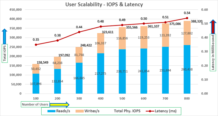
The chart below shows the TPM and System Utilization for the same above tests on CDBDB Database for running the workload from 100 users to 800 users.
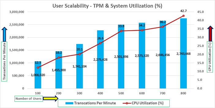
We also ran the maximum number of users (800) test for 24-hour period to check the system performance. The screenshot below highlights the database summary while running the swingbench SOE workload for 24-hour test duration. The container database “CDBDB” was running with one pluggable database as “PDBSOE.”
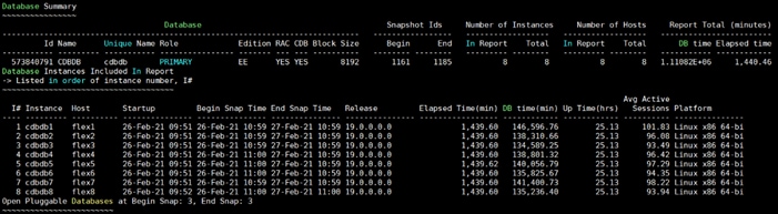
The screenshot below captured from Oracle AWR report shows the “Top Timed Events” for the CDBDB database for the entire 24-hour duration of the test.
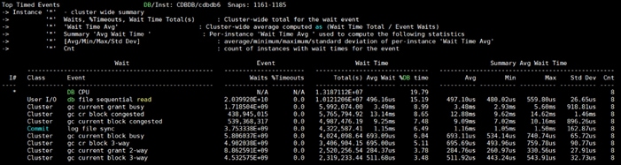
The screenshot below captured from Oracle AWR report highlights the Physical Reads/Sec, Physical Writes/Sec and Transactions per Seconds for the Container CDBDB Database. We captured about 365k IOPS (243k Reads/s and 123k Writes/s) with the 44k TPS while running multiple databases workloads.
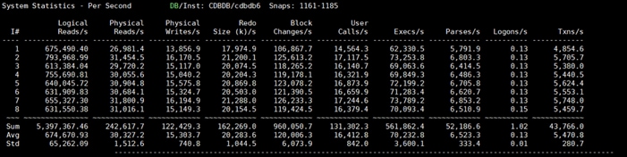
The screenshot below captured from Oracle AWR report shows the CDBDB database “IO Profile” for the “Reads/s” and “Writes/s” requests for the entire 24-hour duration of the test. The Total Requests (Read and Write Per Second) were around “377k” with Total (MB) Read+Write Per Second was around “3212” MB/s for the CDBDB database while running the workload test on one database.
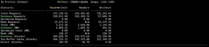
The screenshot below shows the NetApp Storage array “Q S P S (qos statistics performance show)” when one OLTP database was running the workload. The screenshot shows the average IOPS “380k” with the average throughput of “3.3 GB/s” with the average latency around “0.6 millisecond”. The storage cluster utilization during the above test was around 55% which was an indication that storage hasn’t reached the threshold and could take more load.
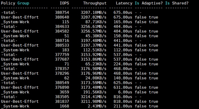
For the entire 24-hour test, we observed the system performance (IOPS and Throughput) was consistent throughout and we did not observe any dips in performance while running one OLTP database stress test.
Multiple (Two) OLTP Databases Performance
For running multiple OLTP database workload, we created one container database CDBDB and two pluggable database PDBSOE and PDBFIN as explained earlier. We ran the swingbench SOE workload on both the databases at the same time with varying the total number of users on both the databases from 400 Users to 1200 Users. Each user scale iteration test was run for at least 3 hours and for each test scenario, we captured the Oracle AWR reports to check the overall system performance below.
Table 14 lists the IOPS and System Utilization for each of the pluggable databases while running the workload from total of 400 users to 1200 users across all the eight RAC nodes.
Table 14. IOPS and System Utilization for Pluggable Databases
| Users |
IOPS for SOE |
IOSP for OLTP |
Total IOPS |
System Utilization (%) |
| 400 |
195,832 |
144,473 |
340,305 |
40.1 |
| 600 |
238,797 |
165,021 |
403,818 |
45.2 |
| 800 |
242,408 |
167,956 |
410,364 |
46.8 |
| 1000 |
250,463 |
171,547 |
422,010 |
48.7 |
| 1200 |
250,549 |
170,831 |
421,380 |
48.9 |
The chart below shows the IOPS and System Utilization for the overall CDBDB Database while running the database workload on both the databases at the same time.
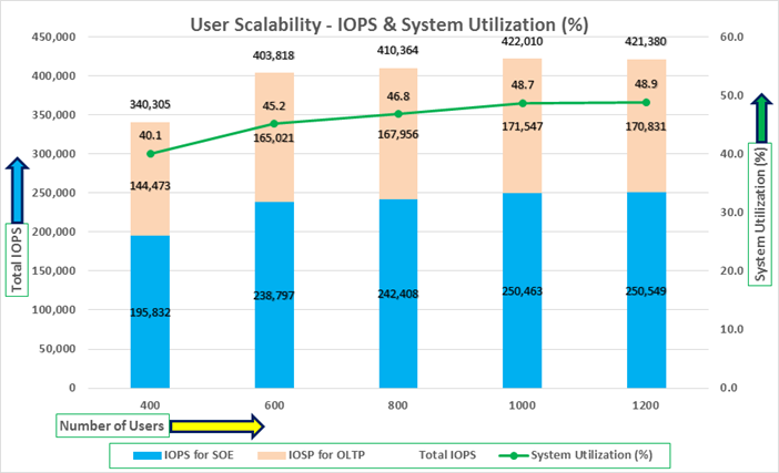
As shown in the chart above, we observed both the databases were linearly scaling the IOPS after increasing and scaling more and more users. We observed average 422k IOPS with overall system utilization around 49% when scaling maximum number of users on multiple database workload test. After increasing users beyond certain level, we observed more GC cluster events and overall similar IOPS around 420k.
Table 15 lists the Transactions per Seconds (TPS) and Transactions per Minutes (TPM) for each of the pluggable databases while running the workload from total of 400 users to 1200 users across all 8 RAC nodes.
Table 15. Transactions per Seconds and Transactions per Minutes
| Users |
TPS for SOE |
TPS for OLTP |
Total TPS |
Total TPM |
| 400 |
24,602 |
16,406 |
41,008 |
2,460,480 |
| 600 |
28,182 |
18,758 |
46,940 |
2,816,400 |
| 800 |
29,023 |
19,349 |
48,372 |
2,902,320 |
| 1000 |
29,126 |
20,431 |
49,557 |
2,973,420 |
| 1200 |
29,143 |
20,302 |
49,445 |
2,966,700 |
The chart below shows the Transactions per Seconds (TPS) for the same tests (above) on CDBDB Database for running the workload on both pluggable databases.
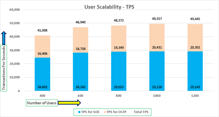
We also ran the maximum number of users test for 24-hour period to check the system overall performance. The screenshot below highlights the database summary while running the swingbench SOE workload for 24-hour test duration on both the databases. The container database “CDBDB” was running with two pluggable databases as “PDBSOE” and “PDBFIN.”
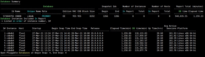
The screenshot shown below was captured from Oracle AWR report while running the Swingbench SOE workload tests on both OLTP databases for 24-hours. The screenshot shows the “OS Statistics by Instance” while the system was running mixed workload. As shown below, the workload was equally spread across all the databases clusters while the average CPU utilization was around 48% overall.
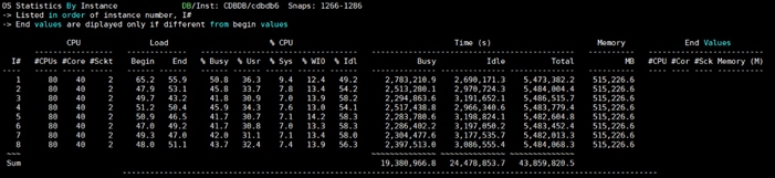
The screenshot shown below captured from Oracle AWR report shows the “Top Timed Events” for the CDBDB database for the entire 24-hour duration of the test.
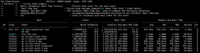
The screenshot shown below captured from Oracle AWR report highlights the Physical Reads/Sec, Physical Writes/Sec and Transactions per Seconds for the Container CDBDB Database. We captured about 432k IOPS (286k Reads/s and 146k Writes/s) with the 51k TPS while running multiple databases workloads.
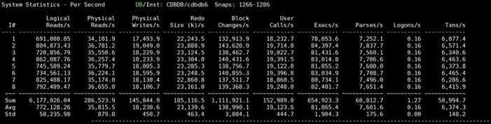
The screenshot below shows the NetApp Storage array “Q S P S (qos statistics performance show)” when two OLTP database was running the workload at the same time. The screenshot shows the average IOPS “430k” with the average throughput of “3.7 GB/s” with the average latency around “0.75 millisecond”. In the multi-database use-case the same behavior of storage cluster utilization (~55%) was observed.
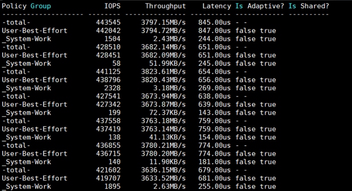
The screenshot below captured from Oracle AWR report shows the CDBDB database “IO Profile” for the “Reads/s” and “Writes/s” requests for the entire duration of the test. As the screenshots shows, the Total Requests (Read and Write Per Second) were around “438k” with Total (MB) Read+Write Per Second was around “3766” MB/s for the CDBDB database while running the workload test on two databases.
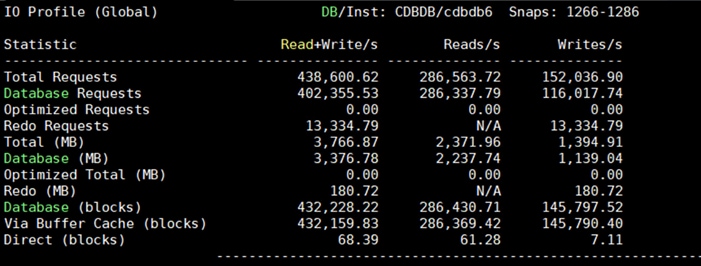
The screenshot below captured from Oracle AWR report shows the CDBDB database “Interconnect Client Statistics Per Second” for the entire duration of the test. As the screenshots shows, Interconnect Sent and Received Statistics were average around “2185 MB/s” while running both the OLTP database workload test.
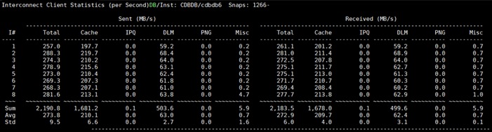
For the entire 24-hour test, we observed the system performance (IOPS, Latency and Throughput) was consistent throughout and we did not observe any dips in performance while running multiple OLTP database stress test.
DSS database workloads are generally sequential in nature, read intensive and exercise large IO size. DSS database workload runs a small number of users that typically exercise extremely complex queries that run for hours. For running oracle database multitenancy architecture, we configured one container database as DSSDB and into that container, we created one pluggable database as PDBSH as explained earlier.
We configured 5.1 TB of PDBSH pluggable database by loading Swingbench “SH” schema into Datafile Tablespace. The screenshot below shows the database summary for the “DSSDB” database running for 24-hour duration. The container database “DSSDB” was also running with one pluggable databases “PDBSH” and the pluggable database was running the Swingbench SH workload for the entire 24-hour duration of the test.
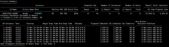
The screenshot below captured from Oracle AWR report shows the DSSDB database “IO Profile” for the “Reads/s” and “Writes/s” requests for the entire 24-hour duration of the test. As the screenshots shows, the Total MB (Read and Write Per Second) were around “10,527 MB/s” for the DSSDB database while running this test.
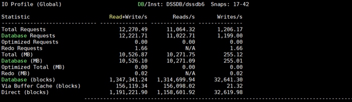
The screenshot shown below shows the NetApp storage array performance (Q S P S (qos statistics performance show)) captured while running Swingbench SH workload on one DSS database. The screenshot shows the average throughput of “11.8 GB/s” with the average latency around “9 millisecond.”
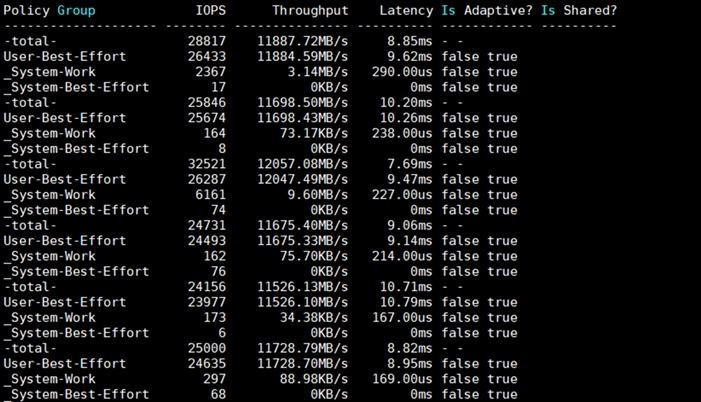
As shown above, the database performance was consistent throughout the test and we did not observe any dips in performance for entire period of 24-hour test. The storage cluster utilization in this case was around 45% during the DSS only workload.
Multiple OLTP and DSS Databases Performance
In this test, we ran Swingbench SOE workloads on both the OLTP (PDBSOE + PDBFIN) databases and Swingbench SH workload on one DSS (PDBSH) Database at the same time and captured the overall system performance. We captured the system performance on small random queries presented via OLTP databases as well as large and sequential transactions submitted via DSS database workload as documented below.
The screenshot below shows the database summary for the “CDBDB” database running for a 12-hour duration. The container database “CDBDB” was running with both the pluggable databases “PDBSOE” and “PDBFIN” and both the pluggable databases were running the Swingbench SOE workload for the entire 12-hour duration of the test.
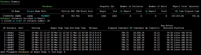
The screenshot below shows the database summary for the “DSSDB” database running for a 12-hour duration. The container database “DSSDB” was also running with one pluggable databases “PDBSH” and the pluggable database was running the Swingbench SH workload for the entire 12-hour duration of the test.
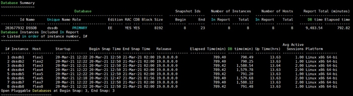
The screenshot shown below was captured from Oracle AWR report while running the Swingbench SOE and SH workload tests on all the three databases for 12-hours. The screenshot shows the “OS Statistics by Instance” while the system was running mixed workload. As shown below, the workload was equally spread across all the databases clusters while the average CPU utilization was around 32% overall.
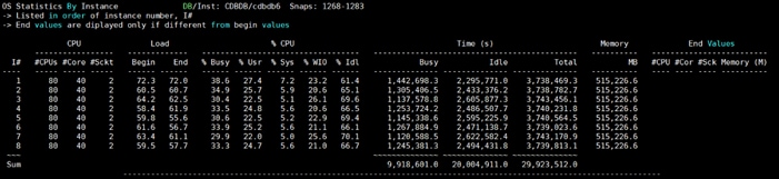
The screenshot below captured from Oracle AWR report shows the “Top Timed Events” for the CDBDB database while running Swingbench SOE workloads on both the pluggable (PDBSOE and PDBFIN) databases for the entire 12-hour duration of the test.
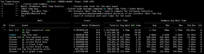
The screenshot below captured from Oracle AWR report highlights the Physical Reads/Sec, Physical Writes/Sec and Transactions per Seconds for the Container CDBDB Database. We captured around 326k IOPS (217k Reads/s and 109k Writes/s) with the 38k TPS while running multiple databases workloads.
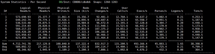
The screenshot below captured from Oracle AWR report shows the CDBDB database “IO Profile” for the “Reads/s” and “Writes/s” requests for the entire 12-hour duration of the test. As the screenshots shows, the Total Requests (Read and Write Per Second) were around “325k” with Total (MB) Read+Write Per Second was around “2813” MB/s for the CDBDB database while running the mixed workload test.
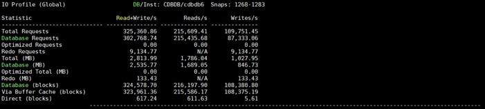
The screenshot below captured from Oracle AWR report shows the CDBDB database “Interconnect Client Statistics Per Second” for the entire 12-hour duration of the test. As the screenshots shows, Interconnect Sent and Received Statistics were average around “1690 MB/s” while running the mixed workload test.
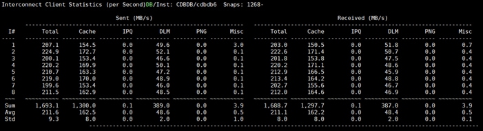
The screenshot below captured from Oracle AWR report shows the “Top Timed Events” for the DSSDB database while running Swingbench SH workloads on the pluggable (PDBFIN) database for the entire 12-hour duration of the test.
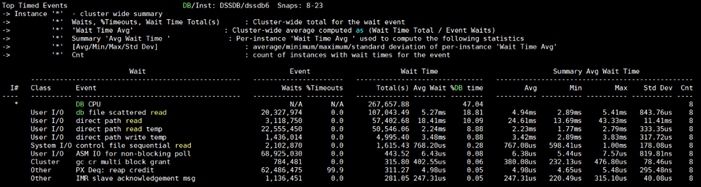
The screenshot below captured from Oracle AWR report shows the DSSDB database “IO Profile” for the “Reads/s” and “Writes/s” requests for the entire 12-hour duration of the test. As the screenshots shows, the Total MB (Read and Write Per Second) were around “3700 MB/s” for the DSSDB database while running this test.
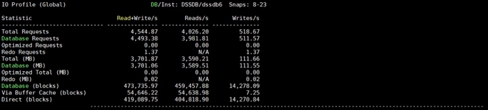
The screenshot below shows the NetApp Storage array “Q S P S (qos statistics performance show)” when all the databases were running the workloads at the same time. The screenshot shows the average IOPS “325k” with the average throughput of “7 GB/s” with the average latency around “1 millisecond.”
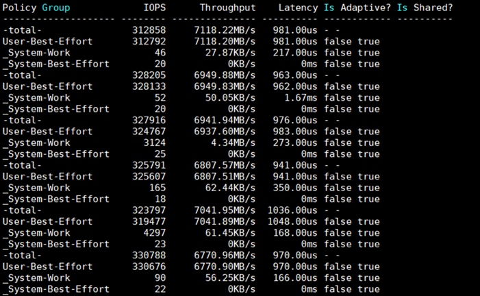
The screenshot below also shows the NetApp Storage array “statistics”. The screenshot shows the average CPU busy around “63%” with “7.5 GB/s” disk read and “1.4 GB/s” disk write when all the databases were running the workloads at the same time. The storage cluster utilization was the highest with both OLTP and DSS running together generating around ~9GB/sec throughput.

The screenshot below shows the NetApp Array GUI when all the databases were running the workloads at the same time.
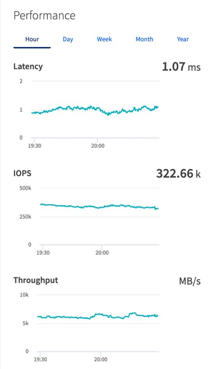
When we ran multiple (OLTP and DSS) databases workloads together, we achieved average around “335k” IOPS, “8.9 GB/s” Throughput with the average latency around “2 milliseconds.” For the entire 12-hour tests, we observed the system performance (IOPS and Throughput) was consistent throughout and we did not observe any dips in performance while running these tests.
The goal of these tests was to ensure that reference architecture withstands commonly occurring failures due to either unexpected crashes, hardware failures or human errors. We conduct many hardware (disconnect power), software (process kills) and OS specific failures that simulate the real world scenarios under stress condition. In the destructive testing, we will also demonstrate unique failover capabilities of Cisco UCS components. Table 16 highlights the test cases.
Table 16. Hardware Failover Tests
| Test Scenario |
Tests Performed |
| Test 1: Cisco UCS Chassis IOM Links Failure |
Run the system on full Database workload. Disconnect one or two links from each Chassis 1 IOM and Chassis 2 IOM by pulling it out and reconnect it after 10-15 minutes. Capture the impact on overall database performance. |
| Test 2: FI – A Failure |
Run the system on full Database workload. Power Off “FI – A” and check the network traffic on “FI – B” and capture the impact on overall database performance. |
| Test 3: FI – B Failure |
Run the system on full Database workload. Power Off “FI – B” and check the network traffic on “FI – A” and capture the impact on overall system performance. |
| Test 4: MDS – A Switch Failure |
Run the system on full Database workload. Power Off “MDS – A” switch and check the network and storage traffic on “MDS – B” switch. Capture the impact on overall database performance. |
| Test 5: MDS – B Switch Failure |
Run the system on full Database workload. Power Off “MDS – B” switch and check the network and storage traffic on “MDS – A” switch. Capture the impact on overall system performance |
| Test 6: Storage Controller Links Failure |
Run the system on full Database workload. Disconnect one or two FC links from each of the NetApp Storage Controller by pulling it out and reconnect it after 10-15 minutes. Capture the impact on overall database performance. |
| Test 7: Server Node Failure |
Run the system on full Database workload. Power Off one Linux Host and check the impact on database performance. |
The architecture below illustrates various failure scenario which can be occurred due to either unexpected crashes or hardware failures.
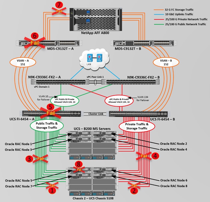
As shown above, Scenario 1 and/or scenario 2 represents the Chassis IOM link failures. Also, scenario 3 and/or 4 represents the Chassis all IOM links failure. Scenario 5 represents the UCS FI – A failure and similarly, scenario 6 represents the MDS Switch – A failure. Scenario 7 represents the NetApp Storage Controllers link failures and Scenario 8 represents one of the Server Node Failure.
As previously explained, we configured to carry Oracle Public Network traffic on “VLAN 134” through FI – A and Oracle Private Interconnect Network traffic on “VLAN 10” through FI – B under normal operating conditions before the failover tests.
The snapshots below show a complete infrastructure details of MAC address and VLAN information for UCS FI – A and FI – B Switches before failover test. Log into FI – A and type “connect nxos a” then type “show mac address-table” to see all the VLAN connection on the switch as:
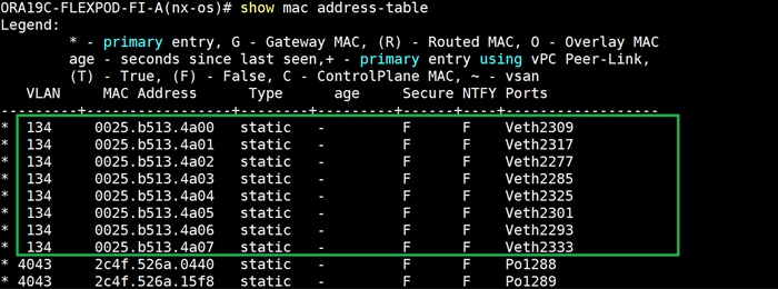
Similarly, log into FI – B and type “connect nxos b” then type “show mac address-table” to see all the VLAN connection on the switch as follows:
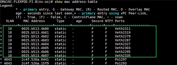
![]() All the Hardware failover tests were conducted during all the three databases (PDBSOE, PDBFIN and PDBSH) running Swingbench mixed workloads.
All the Hardware failover tests were conducted during all the three databases (PDBSOE, PDBFIN and PDBSH) running Swingbench mixed workloads.
Test 1 – Cisco UCS Chassis IOM Links Failure
We conducted IOM Links failure test on Cisco UCS Chassis 1 and Chassis by disconnecting one of the server port link cable from the Chassis as shown below.
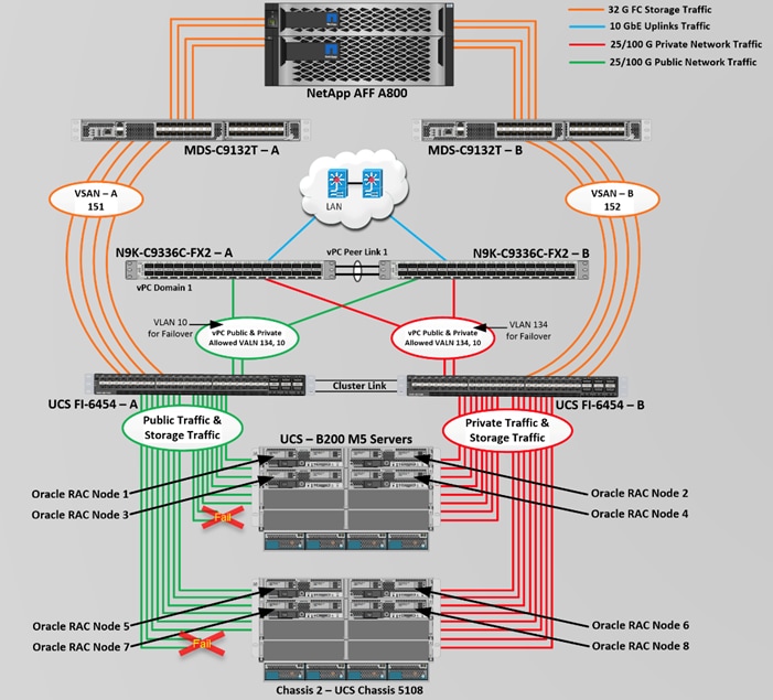
Unplug two server port cables from Chassis 1 and Chassis 2 each and check the MAC address and VLAN traffic information on both UCS FI. The screenshot below shows network traffic on FI – A when one link from Chassis 1 and one link from Chassis 2 IOM Failed.
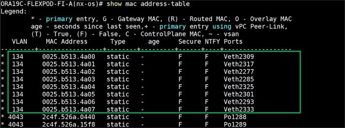
Also, we logged into the storage array and checked the database workload performance as shown below.
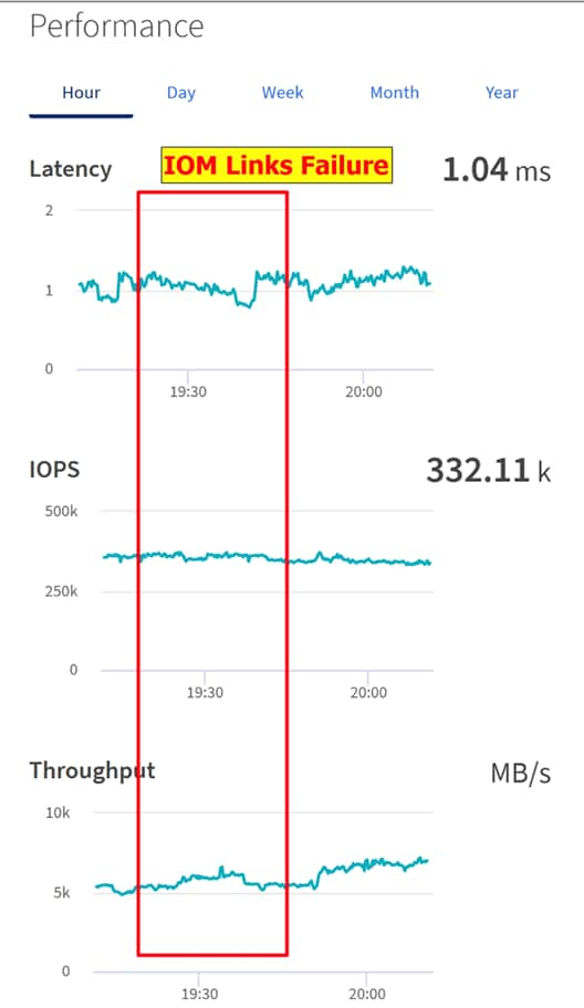
As shown in the screenshot above, we noticed no disruption in public, private and storage network traffic even after multiple IOM links failure from both the Chassis because of the Cisco UCS Port-Channel Feature.
We conducted a hardware failure test on FI – A by disconnecting power cable to the Fabric Interconnect Switch.
The figure below illustrates how during FI – A switch failure, the respective nodes (flex1, flex2, flex3 and flex4) on chassis 1 and nodes (flex5, flex6, flex7 and flex8) on chassis 2 will fail over the public network interface MAC addresses and its VLAN network traffic 134 to FI – B. However, storage traffic VSANs from FI – A switch were not able to failover to FI – B because of those storage interfaces traffic is not capable of failing over to another switch.
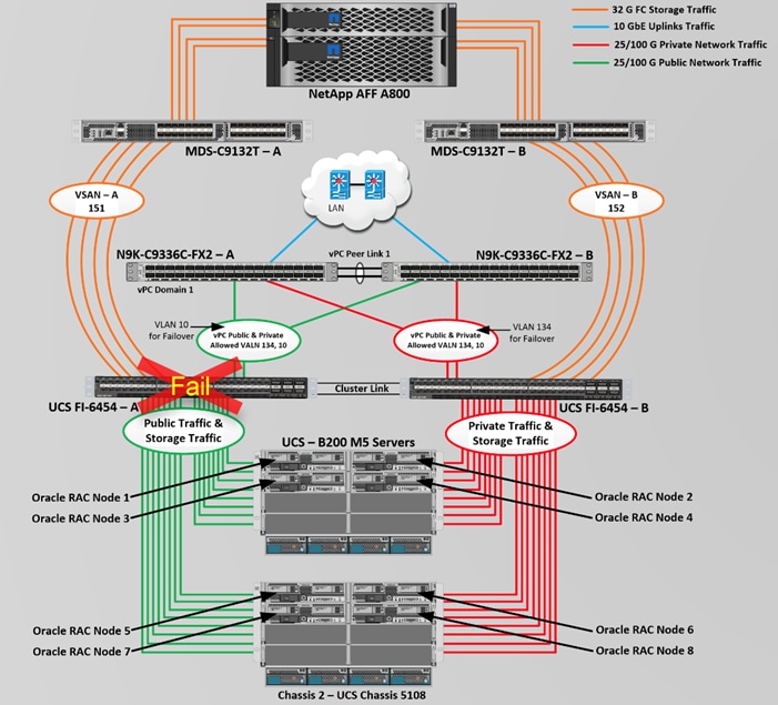
Log into FI – B and type “connect nxos” then type “show mac address-table” to see all VLAN connection on FI – B.
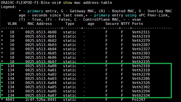
In the screenshot above, we noticed when the FI – A failed, it would route all the Public Network traffic of VLAN 134 to FI – B. So, FI – A Failover did not cause any disruption to Private and Public Network Traffic. However, Storage Network Traffic for VSAN 151 were not able to fail-over to another FI Switch and thus we lost half of the storage traffic connectivity from the Oracle RAC Databases to Storage Array. The below screenshot shows the NetApp Storage Array performance of the mixed workloads on all the databases while one of the FI failed.
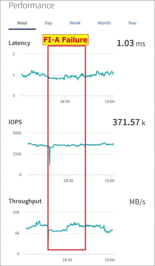
We also recorded performance of the databases from the storage array “Q S P S (qos statistics performance show)” when all the databases were running the workloads and FI – A failure occurred as shown below.
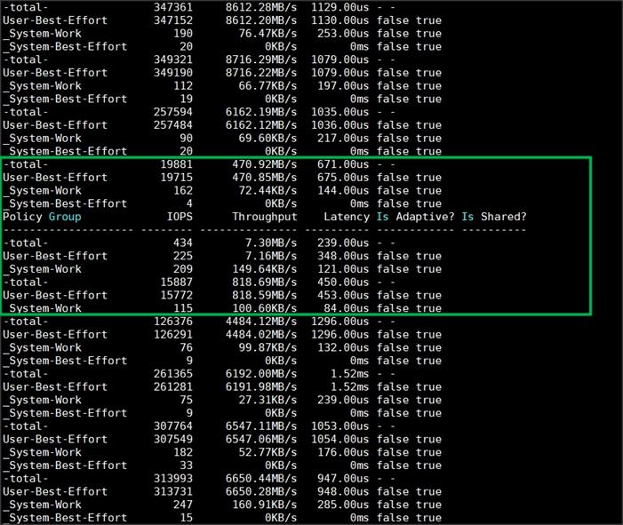
When we disconnect power from FI – A, it causes momentary impact on performance on overall total IOPS, latency on OLTP as well as throughput on DSS database for few seconds but notice that we did not see any interruption in any Private, Public and Storage Network Traffic on IO Service Requests to the storage.
We noticed this behavior because each server node can failover vNICs from one fabric interconnect switch to another fabric interconnect switch but there is no vHBA storage traffic failover from one fabric interconnect switch to another fabric interconnect switch. Therefore, in case of any one fabric interconnect failure, we would lose half of the number of vHBAs or storage paths and consequently we observed momentary databases performance impact for few seconds on the overall system as shown above.
After plugging back power cable to FI – A Switch, the respective nodes (flex1, flex2, flex3 and flex4) on chassis 1 and nodes (flex5, flex6, flex7 and flex8) on chassis 2 will route back the MAC addresses and its VLAN public network traffic 134 to FI – A. After FI – A arrives in normal operating state, all the nodes to storage connectivity, the operating system level multipath configuration will bring back all the path back to active and database performance will resume to peak performance.
Similarly, we conducted a hardware failure test on FI – B by disconnecting power cable to the Fabric Interconnect B Switch.
The figure below illustrates how during FI – B switch failure, the respective nodes (flex1, flex2, flex3 and flex4) on chassis 1 and nodes (flex5, flex6, flex7 and flex8) on chassis 2 will fail over the private network interface MAC addresses and its VLAN network traffic 10 to FI – A. However, storage traffic VSANs from FI – B switch were not able to failover to FI – A because of those storage interfaces traffic is not capable of failing over to another switch.
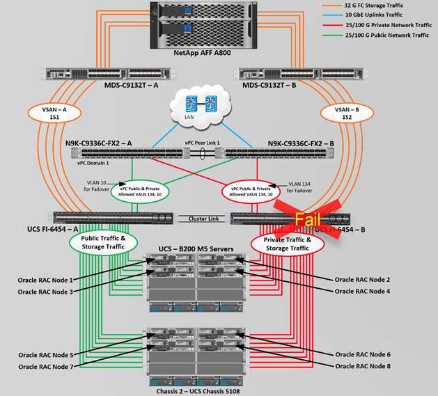
Log into FI – A and type “connect nxos” then type “show mac address-table” to see all VLAN connection on FI – A.
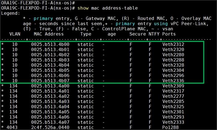
We noticed in the screenshot above, when the FI – B failed, it would route all the Private Network traffic of VLAN 10 to FI – A. So, FI – B Failover did not cause any disruption to Private and Public Network Traffic. However, Storage Network Traffic for VSAN 152 were not able to fail-over to another FI Switch and thus we lost half of the storage traffic connectivity from the Oracle RAC Databases to Storage Array. The screenshot below shows the NetApp Storage Array performance of the mixed workloads on all the databases while one of the FI failed.
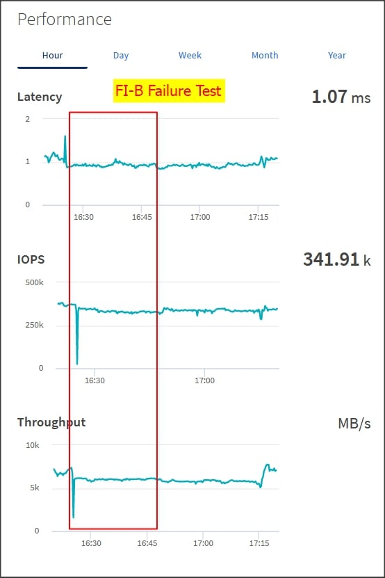
We also recorded performance of the databases from the storage array “Q S P S (qos statistics performance show)” when all the databases were running the workloads and FI – B failure occurred. Similar to previous FI – A failure test, in this FI – B failure test, we captured momentary impact on performance on overall total IOPS, latency and throughput for few seconds but we did not see any interruption in any Private, Public and Storage Network Traffic on IO Service Requests to the storage.
We noticed this behavior because each server node can failover vNICs from one fabric interconnect switch to another fabric interconnect switch but there is no vHBA storage traffic failover from one fabric interconnect switch to another fabric interconnect switch. Therefore, in case of any one fabric interconnect failure, we would lose half of the number of vHBAs or storage path and consequently we observe momentary databases performance impact for few seconds on the overall system as shown above.
After plugging back power cable to FI – B Switch, the respective nodes (flex1, flex2, flex3 and flex4) on chassis 1 and nodes (flex5, flex6, flex7 and flex8) on chassis 2 will route back the MAC addresses and its VLAN private network traffic 10 to FI – B. After FI – B arrives in normal operating state, all the nodes to storage connectivity, the operating system level multipath configuration will bring back all the path back to active and database performance will resume to peak performance.
Test 4 and 5: MDS Switch Failure
We conducted hardware failure test on MDS Switch – A by disconnecting power cable to the Switch and checking the storage network traffic on MDS Switch – B and overall system as shown below.
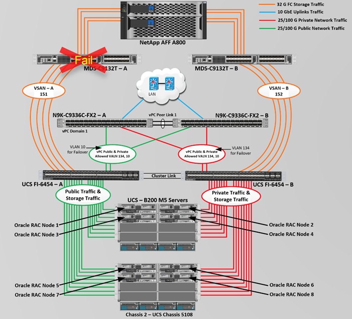
Similar to FI failure tests, we observed some impact on all three databases performance as we lost half of the VSAN (VSAN-A 151) traffic. While VSAN-A (151) stays locally into the switch and only carry storage traffic through the MDS switch A, VSAN-A doesn’t failover to MDS Switch B therefore we reduced server to storage connectivity into half during MDS Switch A failure. However, failure in MDS Switch did not cause any disruption to Private and Public Network Traffic.
We also recorded performance of the databases from the storage array “Q S P S “where we observed momentary impact on performance on overall IOPS, latency on OLTP as well as throughput on DSS database for few seconds.
After plugging back power cable to MDS Switch A, the operating system level multipath configuration will bring back all the path back to active and database performance will resume to peak performance.
Test 6: Storage Controller Links Failure
We performed storage controller link failure test by disconnecting two of the FC links from the NetApp Array from each of the storage controller as shown below:
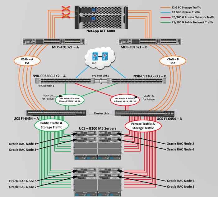
Similar to FI and MDS failure tests, storage link failure did not cause any disruption to Private, Public and Storage Network Traffic. After plugging back FC links to storage controller, MDS Switch and Storage array links comes back online, and the operating system level multipath configuration will bring back all the path back to active and database performance will resume to peak performance.
In this test, we power down one node from the RAC cluster and run the swingbench workload on all of the databases to check the overall system performance. We didn’t observe any performance impact on overall database IOPS, latency and throughput after losing one node from the system.
We completed an additional failure scenario and validated that there is no single point of failure in this reference design.
The Cisco Unified Computing System™ (Cisco UCS®) is a next-generation data center platform that unites computing, network, storage access, and virtualization into a single cohesive system. Cisco UCS is an ideal platform for the architecture of mission critical database workloads such as Oracle RAC. The FlexPod Datacenter with NetApp All Flash AFF system is a converged infrastructure platform that combines best-of breed technologies from Cisco and NetApp into a powerful converged platform for enterprise applications. The pre-validated FlexPod architecture delivers proven value, agility, and performance that drive higher productivity, faster decision making, and greater opportunities for growth.
An essential feature for Oracle databases deployed on shared enterprise system is the ability to deliver consistent and dependable high performance. High performance must be coupled with non-disruptive operations, high availability, scalability, and storage efficiency. Customers can depend on Cisco UCS and NetApp Clustered Data ONTAP Storage to provide these essential elements. Built on clustered Data ONTAP unified scale-out architecture, AFF consistently meets or exceeds the high-performance demands of Oracle databases. It also provides rich data management capabilities, such as integrated data protection and non-disruptive upgrades and data migration. These features allow customers to eliminate performance silos and seamlessly integrate AFF into a shared infrastructure.
Clustered Data ONTAP 9.7 delivers an enhanced inline compression capability that significantly reduces the amount of flash storage required and carries near-zero effects on system performance and doesn’t impact the application performance. The inline de-duplication won’t help databases much but doesn’t cause any harm in terms of CPU cycles when it is turned on and can help other non-database objects sharing the same storage cluster. The combination of Cisco UCS, NetApp and Oracle Real Application Cluster Database architecture can provide the following benefits to accelerate your IT transformation
Cisco UCS stateless computing architecture provided by the Service Profile capability of Cisco UCS allows fast, non-disruptive workload changes to be executed simply and seamlessly across the integrated UCS infrastructure and Cisco x86 servers.
A single platform built from unified compute, fabric, and storage technologies, allowing you to scale to large-scale data centers without architectural changes
Enabling faster deployments, greater flexibility of choice, efficiency, high availability, and lower risk.
MDS 9132T Switch Configuration
ORA19C-FLEXPOD-MDS-A# show running-config
version 8.4(1)
power redundancy-mode redundant
feature npiv
feature fport-channel-trunk
feature telnet
role name default-role
description This is a system defined role and applies to all users.
rule 5 permit show feature environment
rule 4 permit show feature hardware
rule 3 permit show feature module
rule 2 permit show feature snmp
rule 1 permit show feature system
ip domain-lookup
ip host ORA19C-FLEXPOD-MDS-A 10.29.134.50
aaa group server radius radius
snmp-server user admin network-admin auth md5 0xeafc179c4eb2875cdbca434a323e13b2 priv 0xeafc179c4eb2875cdbca434a323e13b2 localizedkey
vsan database
vsan 151 name "VSAN-FI-A"
device-alias mode enhanced
device-alias database
device-alias name Flex1-hba0 pwwn 20:00:00:25:b5:99:aa:00
device-alias name Flex1-hba2 pwwn 20:00:00:25:b5:99:aa:01
device-alias name Flex2-hba0 pwwn 20:00:00:25:b5:99:aa:02
device-alias name Flex2-hba2 pwwn 20:00:00:25:b5:99:aa:03
device-alias name Flex3-hba0 pwwn 20:00:00:25:b5:99:aa:04
device-alias name Flex3-hba2 pwwn 20:00:00:25:b5:99:aa:05
device-alias name Flex4-hba0 pwwn 20:00:00:25:b5:99:aa:06
device-alias name Flex4-hba2 pwwn 20:00:00:25:b5:99:aa:07
device-alias name Flex5-hba0 pwwn 20:00:00:25:b5:99:aa:08
device-alias name Flex5-hba2 pwwn 20:00:00:25:b5:99:aa:09
device-alias name Flex6-hba0 pwwn 20:00:00:25:b5:99:aa:0a
device-alias name Flex6-hba2 pwwn 20:00:00:25:b5:99:aa:0b
device-alias name Flex7-hba0 pwwn 20:00:00:25:b5:99:aa:0c
device-alias name Flex7-hba2 pwwn 20:00:00:25:b5:99:aa:0d
device-alias name Flex8-hba0 pwwn 20:00:00:25:b5:99:aa:0e
device-alias name Flex8-hba2 pwwn 20:00:00:25:b5:99:aa:0f
device-alias name A800-NVMe-01-2a pwwn 20:14:00:a0:98:b9:25:08
device-alias name A800-NVMe-02-2a pwwn 20:16:00:a0:98:b9:25:08
device-alias name FlexPod-A800-01-2a pwwn 20:01:00:a0:98:b9:25:08
device-alias name FlexPod-A800-01-2b pwwn 20:02:00:a0:98:b9:25:08
device-alias name FlexPod-A800-02-2a pwwn 20:05:00:a0:98:b9:25:08
device-alias name FlexPod-A800-02-2b pwwn 20:06:00:a0:98:b9:25:08
device-alias commit
system default zone distribute full
zone smart-zoning enable vsan 151
zoneset distribute full vsan 151
!Active Zone Database Section for vsan 151
zone name Flex1A-Boot vsan 151
member device-alias Flex1-hba0 init
member device-alias FlexPod-A800-01-2a target
member device-alias FlexPod-A800-02-2a target
zone name Flex2A-Boot vsan 151
member device-alias Flex2-hba0 init
member device-alias FlexPod-A800-01-2a target
member device-alias FlexPod-A800-02-2a target
zone name Flex3A-Boot vsan 151
member device-alias Flex3-hba0 init
member device-alias FlexPod-A800-01-2a target
member device-alias FlexPod-A800-02-2a target
zone name Flex4A-Boot vsan 151
member device-alias Flex4-hba0 init
member device-alias FlexPod-A800-01-2a target
member device-alias FlexPod-A800-02-2a target
zone name Flex5A-Boot vsan 151
member device-alias Flex5-hba0 init
member device-alias FlexPod-A800-01-2a target
member device-alias FlexPod-A800-02-2a target
zone name Flex6A-Boot vsan 151
member device-alias Flex6-hba0 init
member device-alias FlexPod-A800-01-2a target
member device-alias FlexPod-A800-02-2a target
zone name Flex7A-Boot vsan 151
member device-alias Flex7-hba0 init
member device-alias FlexPod-A800-01-2a target
member device-alias FlexPod-A800-02-2a target
zone name Flex8A-Boot vsan 151
member device-alias Flex8-hba0 init
member device-alias FlexPod-A800-01-2a target
member device-alias FlexPod-A800-02-2a target
zone name Flex1A-NVMe vsan 151
member device-alias Flex1-hba2 init
member device-alias A800-NVMe-01-2a target
member device-alias A800-NVMe-02-2a target
zone name Flex2A-NVMe vsan 151
member device-alias Flex2-hba2 init
member device-alias A800-NVMe-01-2a target
member device-alias A800-NVMe-02-2a target
zone name Flex3A-NVMe vsan 151
member device-alias Flex3-hba2 init
member device-alias A800-NVMe-01-2a target
member device-alias A800-NVMe-02-2a target
zone name Flex4A-NVMe vsan 151
member device-alias Flex4-hba2 init
member device-alias A800-NVMe-01-2a target
member device-alias A800-NVMe-02-2a target
zone name Flex5A-NVMe vsan 151
member device-alias Flex5-hba2 init
member device-alias A800-NVMe-01-2a target
member device-alias A800-NVMe-02-2a target
zone name Flex6A-NVMe vsan 151
member device-alias Flex6-hba2 init
member device-alias A800-NVMe-01-2a target
member device-alias A800-NVMe-02-2a target
zone name Flex7A-NVMe vsan 151
member device-alias Flex7-hba2 init
member device-alias A800-NVMe-01-2a target
member device-alias A800-NVMe-02-2a target
zone name Flex8A-NVMe vsan 151
member device-alias Flex8-hba2 init
member device-alias A800-NVMe-01-2a target
member device-alias A800-NVMe-02-2a target
zoneset name Flex-A vsan 151
member Flex1A-Boot
member Flex2A-Boot
member Flex3A-Boot
member Flex4A-Boot
member Flex5A-Boot
member Flex6A-Boot
member Flex7A-Boot
member Flex8A-Boot
member Flex1A-NVMe
member Flex2A-NVMe
member Flex3A-NVMe
member Flex4A-NVMe
member Flex5A-NVMe
member Flex6A-NVMe
member Flex7A-NVMe
member Flex8A-NVMe
zoneset activate name Flex-A vsan 151
do clear zone database vsan 151
!Full Zone Database Section for vsan 151
zone name Flex1A-Boot vsan 151
member device-alias Flex1-hba0 init
member device-alias FlexPod-A800-01-2a target
member device-alias FlexPod-A800-02-2a target
zone name Flex2A-Boot vsan 151
member device-alias Flex2-hba0 init
member device-alias FlexPod-A800-01-2a target
member device-alias FlexPod-A800-02-2a target
zone name Flex3A-Boot vsan 151
member device-alias Flex3-hba0 init
member device-alias FlexPod-A800-01-2a target
member device-alias FlexPod-A800-02-2a target
zone name Flex4A-Boot vsan 151
member device-alias Flex4-hba0 init
member device-alias FlexPod-A800-01-2a target
member device-alias FlexPod-A800-02-2a target
zone name Flex5A-Boot vsan 151
member device-alias Flex5-hba0 init
member device-alias FlexPod-A800-01-2a target
member device-alias FlexPod-A800-02-2a target
zone name Flex6A-Boot vsan 151
member device-alias Flex6-hba0 init
member device-alias FlexPod-A800-01-2a target
member device-alias FlexPod-A800-02-2a target
zone name Flex7A-Boot vsan 151
member device-alias Flex7-hba0 init
member device-alias FlexPod-A800-01-2a target
member device-alias FlexPod-A800-02-2a target
zone name Flex8A-Boot vsan 151
member device-alias Flex8-hba0 init
member device-alias FlexPod-A800-01-2a target
member device-alias FlexPod-A800-02-2a target
zone name Flex1A-NVMe vsan 151
member device-alias Flex1-hba2 init
member device-alias A800-NVMe-01-2a target
member device-alias A800-NVMe-02-2a target
zone name Flex2A-NVMe vsan 151
member device-alias Flex2-hba2 init
member device-alias A800-NVMe-01-2a target
member device-alias A800-NVMe-02-2a target
zone name Flex3A-NVMe vsan 151
member device-alias Flex3-hba2 init
member device-alias A800-NVMe-01-2a target
member device-alias A800-NVMe-02-2a target
zone name Flex4A-NVMe vsan 151
member device-alias Flex4-hba2 init
member device-alias A800-NVMe-01-2a target
member device-alias A800-NVMe-02-2a target
zone name Flex5A-NVMe vsan 151
member device-alias Flex5-hba2 init
member device-alias A800-NVMe-01-2a target
member device-alias A800-NVMe-02-2a target
zone name Flex6A-NVMe vsan 151
member device-alias Flex6-hba2 init
member device-alias A800-NVMe-01-2a target
member device-alias A800-NVMe-02-2a target
zone name Flex7A-NVMe vsan 151
member device-alias Flex7-hba2 init
member device-alias A800-NVMe-01-2a target
member device-alias A800-NVMe-02-2a target
zone name Flex8A-NVMe vsan 151
member device-alias Flex8-hba2 init
member device-alias A800-NVMe-01-2a target
member device-alias A800-NVMe-02-2a target
zoneset name Flex-A vsan 151
member Flex1A-Boot
member Flex2A-Boot
member Flex3A-Boot
member Flex4A-Boot
member Flex5A-Boot
member Flex6A-Boot
member Flex7A-Boot
member Flex8A-Boot
member Flex1A-NVMe
member Flex2A-NVMe
member Flex3A-NVMe
member Flex4A-NVMe
member Flex5A-NVMe
member Flex6A-NVMe
member Flex7A-NVMe
member Flex8A-NVMe
interface mgmt0
ip address 10.29.134.50 255.255.255.0
interface port-channel251
switchport trunk allowed vsan 151
switchport description ORA19C-FlexPod-FI-A
switchport rate-mode dedicated
switchport trunk mode off
vsan database
vsan 151 interface port-channel251
vsan 151 interface fc1/5
vsan 151 interface fc1/6
vsan 151 interface fc1/7
vsan 151 interface fc1/8
vsan 151 interface fc1/9
vsan 151 interface fc1/10
vsan 151 interface fc1/11
vsan 151 interface fc1/12
switchname ORA19C-FLEXPOD-MDS-A
cli alias name autozone source sys/autozone.py
line console
line vty
boot kickstart bootflash:/m9100-s6ek9-kickstart-mz.8.4.1.bin
boot system bootflash:/m9100-s6ek9-mz.8.4.1.bin
interface fc1/1
switchport description ORA19C-FlexPod-FI-A-1/1
switchport trunk mode off
port-license acquire
channel-group 251 force
no shutdown
interface fc1/2
switchport description ORA19C-FlexPod-FI-A-1/2
switchport trunk mode off
port-license acquire
channel-group 251 force
no shutdown
interface fc1/3
switchport description ORA19C-FlexPod-FI-A-1/3
switchport trunk mode off
port-license acquire
channel-group 251 force
no shutdown
interface fc1/4
switchport description ORA19C-FlexPod-FI-A-1/4
switchport trunk mode off
port-license acquire
channel-group 251 force
no shutdown
interface fc1/5
switchport trunk allowed vsan 151
switchport description FlexPod-A800-01-2a
switchport trunk mode off
port-license acquire
no shutdown
interface fc1/6
switchport trunk allowed vsan 151
switchport description FlexPod-A800-01-2b
switchport trunk mode off
port-license acquire
no shutdown
interface fc1/7
switchport trunk allowed vsan 151
switchport description FlexPod-A800-02-2a
switchport trunk mode off
port-license acquire
no shutdown
interface fc1/8
switchport trunk allowed vsan 151
switchport description FlexPod-A800-02-2b
switchport trunk mode off
port-license acquire
no shutdown
interface fc1/9
switchport trunk allowed vsan 151
switchport trunk mode off
port-license acquire
no shutdown
interface fc1/10
switchport trunk allowed vsan 151
switchport trunk mode off
port-license acquire
no shutdown
interface fc1/11
switchport trunk allowed vsan 151
switchport trunk mode off
port-license acquire
no shutdown
interface fc1/12
switchport trunk allowed vsan 151
switchport trunk mode off
port-license acquire
no shutdown
ip default-gateway 10.29.134.1
Cisco Nexus 9336C-FX2 Switch Configuration
ORA19C-FLEXPOD-N9K-A# show running-config
version 9.3(3) Bios:version 05.40
hostname ORA19C-FLEXPOD-N9K-A
policy-map type network-qos jumbo
class type network-qos class-default
mtu 9216
cfs eth distribute
feature udld
feature interface-vlan
feature hsrp
feature lacp
feature vpc
feature lldp
ip domain-lookup
system default switchport
system qos
service-policy type network-qos jumbo
vlan 1,10,134
vlan 10
name Oracle_RAC_Private_Network
vlan 134
name Oracle_RAC_Public_Network
spanning-tree port type edge bpduguard default
spanning-tree port type network default
vrf context management
ip route 0.0.0.0/0 10.29.134.1
port-channel load-balance src-dst l4port
vpc domain 1
peer-keepalive destination 10.29.134.53 source 10.29.134.52
auto-recovery
interface Vlan1
interface Vlan134
no shutdown
ip address 10.29.134.253/24
interface port-channel1
description vPC peer-link
switchport mode trunk
switchport trunk allowed vlan 1,10,134
spanning-tree port type network
vpc peer-link
interface port-channel51
description Port-Channel FI-A
switchport mode trunk
switchport trunk allowed vlan 1,10,134
spanning-tree port type edge trunk
mtu 9216
vpc 51
interface port-channel52
description Port-Channel FI-B
switchport mode trunk
switchport trunk allowed vlan 1,10,134
spanning-tree port type edge trunk
mtu 9216
vpc 52
interface Ethernet1/1
description Peer link 100g connected to N9K-B-Eth1/1
switchport mode trunk
switchport trunk allowed vlan 1,10,134
channel-group 1 mode active
interface Ethernet1/2
description Peer link 100g connected to N9K-B-Eth1/2
switchport mode trunk
switchport trunk allowed vlan 1,10,134
channel-group 1 mode active
interface Ethernet1/25
description 100g link to Fabric-Interconnect A port 49
switchport mode trunk
switchport trunk allowed vlan 1,10,134
spanning-tree port type edge trunk
mtu 9216
channel-group 51 mode active
interface Ethernet1/26
description 100g link to Fabric-Interconnect B Port 49
switchport mode trunk
switchport trunk allowed vlan 1,10,134
spanning-tree port type edge trunk
mtu 9216
channel-group 52 mode active
interface Ethernet1/31
description connect to uplink switch
switchport access vlan 134
speed 1000
interface mgmt0
vrf member management
ip address 10.29.134.52/24
line console
line vty
boot nxos bootflash:/nxos.9.3.3.bin
no system default switchport shutdown
Multipath Configuration “/etc/multipath.conf”
[root@flex1 ~]# cat /etc/multipath.conf
defaults {
find_multipaths yes
user_friendly_names yes
enable_foreign NONE
}
blacklist {
}
multipaths {
multipath {
wwid 3600a098038304437575d507956514145
alias Flex1-OS
}
}
Configuration of “/etc/sysctl.conf”
[root@flex1 ~]# cat /etc/sysctl.conf
vm.nr_hugepages=78000
# oracle-database-preinstall-19c setting for fs.file-max is 6815744
fs.file-max = 6815744
# oracle-database-preinstall-19c setting for kernel.sem is '250 32000 100 128'
kernel.sem = 250 32000 100 128
# oracle-database-preinstall-19c setting for kernel.shmmni is 4096
kernel.shmmni = 4096
# oracle-database-preinstall-19c setting for kernel.shmall is 1073741824 on x86_64
kernel.shmall = 1073741824
# oracle-database-preinstall-19c setting for kernel.shmmax is 4398046511104 on x86_64
kernel.shmmax = 4398046511104
# oracle-database-preinstall-19c setting for kernel.panic_on_oops is 1 per Orabug 19212317
kernel.panic_on_oops = 1
# oracle-database-preinstall-19c setting for net.core.rmem_default is 262144
net.core.rmem_default = 262144
# oracle-database-preinstall-19c setting for net.core.rmem_max is 4194304
net.core.rmem_max = 4194304
# oracle-database-preinstall-19c setting for net.core.wmem_default is 262144
net.core.wmem_default = 262144
# oracle-database-preinstall-19c setting for net.core.wmem_max is 1048576
net.core.wmem_max = 1048576
# oracle-database-preinstall-19c setting for net.ipv4.conf.all.rp_filter is 2
net.ipv4.conf.all.rp_filter = 2
# oracle-database-preinstall-19c setting for net.ipv4.conf.default.rp_filter is 2
net.ipv4.conf.default.rp_filter = 2
# oracle-database-preinstall-19c setting for fs.aio-max-nr is 1048576
fs.aio-max-nr = 1048576
# oracle-database-preinstall-19c setting for net.ipv4.ip_local_port_range is 9000 65500
net.ipv4.ip_local_port_range = 9000 65500
Configuration of “/etc/security/limits.d/oracle-database-preinstall-19c.conf”
[root@flex1 ~]# cat /etc/security/limits.d/oracle-database-preinstall-19c.conf
# oracle-database-preinstall-19c setting for nofile soft limit is 1024
oracle soft nofile 1024
# oracle-database-preinstall-19c setting for nofile hard limit is 65536
oracle hard nofile 65536
# oracle-database-preinstall-19c setting for nproc soft limit is 16384
# refer orabug15971421 for more info.
oracle soft nproc 16384
# oracle-database-preinstall-19c setting for nproc hard limit is 16384
oracle hard nproc 16384
# oracle-database-preinstall-19c setting for stack soft limit is 10240KB
oracle soft stack 10240
# oracle-database-preinstall-19c setting for stack hard limit is 32768KB
oracle hard stack 32768
# oracle-database-preinstall-19c setting for memlock hard limit is maximum of 128GB on x86_64 or 3GB on x86 OR 90 % of RAM
### oracle hard memlock 237010305
### oracle hard memlock 237010882
oracle hard memlock 474832847
# oracle-database-preinstall-19c setting for memlock soft limit is maximum of 128GB on x86_64 or 3GB on x86 OR 90% of RAM
### oracle soft memlock 237010305
### oracle soft memlock 237010882
oracle soft memlock 474832847
# oracle-database-preinstall-19c setting for data soft limit is 'unlimited'
oracle soft data unlimited
# oracle-database-preinstall-19c setting for data hard limit is 'unlimited'
oracle hard data unlimited
Configuration of “/etc/udev/rules.d/71-nvme-iopolicy-netapp-ONTAP.rules”
[root@flex1 ~]# cat /etc/udev/rules.d/71-nvme-iopolicy-netapp-ONTAP.rules
### Enable round-robin for NetApp ONTAP
ACTION=="add", SUBSYSTEM=="nvme-subsystem", ATTR{model}=="NetApp ONTAP Controller", ATTR{iopolicy}="round-robin"
Configuration of “/etc/udev/rules.d/80-nvme.rules”
[root@flex1 ~]# cat /etc/udev/rules.d/80-nvme.rules
KERNEL=="nvme[0-9]*n[0-9]*", ENV{DEVTYPE}=="disk", ENV{ID_WWN}=="uuid.7636791b-944f-4adb-941e-0d962639f718", SYMLINK+="asm1", GROUP:="oinstall", OWNER:="grid", MODE:="660"
KERNEL=="nvme[0-9]*n[0-9]*", ENV{DEVTYPE}=="disk", ENV{ID_WWN}=="uuid.1251e1c3-3735-4546-8b39-6654c83620f7", SYMLINK+="asm2", GROUP:="oinstall", OWNER:="grid", MODE:="660"
KERNEL=="nvme[0-9]*n[0-9]*", ENV{DEVTYPE}=="disk", ENV{ID_WWN}=="uuid.e2c15660-bc0c-4bfb-a360-02011bb55b06", SYMLINK+="datacdb01", GROUP:="oinstall", OWNER:="oracle", MODE:="660"
KERNEL=="nvme[0-9]*n[0-9]*", ENV{DEVTYPE}=="disk", ENV{ID_WWN}=="uuid.374102da-60ab-436f-96cd-0a8b4d6d75c8", SYMLINK+="datacdb02", GROUP:="oinstall", OWNER:="oracle", MODE:="660"
KERNEL=="nvme[0-9]*n[0-9]*", ENV{DEVTYPE}=="disk", ENV{ID_WWN}=="uuid.4c1b87f3-f3e2-432e-b13d-435adc5e75d5", SYMLINK+="datacdb03", GROUP:="oinstall", OWNER:="oracle", MODE:="660"
KERNEL=="nvme[0-9]*n[0-9]*", ENV{DEVTYPE}=="disk", ENV{ID_WWN}=="uuid.b9232ee5-afe2-4237-913a-f6b213d382f6", SYMLINK+="datacdb04", GROUP:="oinstall", OWNER:="oracle", MODE:="660"
KERNEL=="nvme[0-9]*n[0-9]*", ENV{DEVTYPE}=="disk", ENV{ID_WWN}=="uuid.6fc2542d-ba50-42a2-907b-e7375709ee0f", SYMLINK+="datadss01", GROUP:="oinstall", OWNER:="oracle", MODE:="660"
KERNEL=="nvme[0-9]*n[0-9]*", ENV{DEVTYPE}=="disk", ENV{ID_WWN}=="uuid.710065e5-c4b1-43af-ae1b-d28662d921fb", SYMLINK+="datadss02", GROUP:="oinstall", OWNER:="oracle", MODE:="660"
KERNEL=="nvme[0-9]*n[0-9]*", ENV{DEVTYPE}=="disk", ENV{ID_WWN}=="uuid.90336e21-bec1-4da5-b64e-d988e8f689c3", SYMLINK+="datadss03", GROUP:="oinstall", OWNER:="oracle", MODE:="660"
KERNEL=="nvme[0-9]*n[0-9]*", ENV{DEVTYPE}=="disk", ENV{ID_WWN}=="uuid.d51f7c79-f7aa-4155-9c92-7e4532e11560", SYMLINK+="datadss04", GROUP:="oinstall", OWNER:="oracle", MODE:="660"
KERNEL=="nvme[0-9]*n[0-9]*", ENV{DEVTYPE}=="disk", ENV{ID_WWN}=="uuid.4a7533cc-f86a-4787-be48-05263a929c42", SYMLINK+="dataslob01", GROUP:="oinstall", OWNER:="oracle", MODE:="660"
KERNEL=="nvme[0-9]*n[0-9]*", ENV{DEVTYPE}=="disk", ENV{ID_WWN}=="uuid.ffc6a134-0f79-4748-8dfe-73bf7a778729", SYMLINK+="dataslob02", GROUP:="oinstall", OWNER:="oracle", MODE:="660"
KERNEL=="nvme[0-9]*n[0-9]*", ENV{DEVTYPE}=="disk", ENV{ID_WWN}=="uuid.231aa3d6-6a14-4ea1-9e4f-32145a97817f", SYMLINK+="dataslob03", GROUP:="oinstall", OWNER:="oracle", MODE:="660"
KERNEL=="nvme[0-9]*n[0-9]*", ENV{DEVTYPE}=="disk", ENV{ID_WWN}=="uuid.0b53d533-6af1-4e1b-ad64-424c0ceaa569", SYMLINK+="dataslob04", GROUP:="oinstall", OWNER:="oracle", MODE:="660"
KERNEL=="nvme[0-9]*n[0-9]*", ENV{DEVTYPE}=="disk", ENV{ID_WWN}=="uuid.938e9f50-0030-471c-b4f7-9f2cd0f45aec", SYMLINK+="dataslob05", GROUP:="oinstall", OWNER:="oracle", MODE:="660"
KERNEL=="nvme[0-9]*n[0-9]*", ENV{DEVTYPE}=="disk", ENV{ID_WWN}=="uuid.faf7a66b-2b20-4a28-8f20-8a2ddd06856d", SYMLINK+="dataslob06", GROUP:="oinstall", OWNER:="oracle", MODE:="660"
KERNEL=="nvme[0-9]*n[0-9]*", ENV{DEVTYPE}=="disk", ENV{ID_WWN}=="uuid.76a65ede-9e0b-4976-8e3d-26c0e6ba859d", SYMLINK+="dataslob07", GROUP:="oinstall", OWNER:="oracle", MODE:="660"
KERNEL=="nvme[0-9]*n[0-9]*", ENV{DEVTYPE}=="disk", ENV{ID_WWN}=="uuid.ad3cc536-4fc1-4844-880a-b5ea6dd74a8c", SYMLINK+="dataslob08", GROUP:="oinstall", OWNER:="oracle", MODE:="660"
KERNEL=="nvme[0-9]*n[0-9]*", ENV{DEVTYPE}=="disk", ENV{ID_WWN}=="uuid.f373f271-7a63-418f-ac52-171b0d8fc302", SYMLINK+="dataslob09", GROUP:="oinstall", OWNER:="oracle", MODE:="660"
KERNEL=="nvme[0-9]*n[0-9]*", ENV{DEVTYPE}=="disk", ENV{ID_WWN}=="uuid.a2df6615-c3ab-4233-93fb-49c0f12eece3", SYMLINK+="dataslob10", GROUP:="oinstall", OWNER:="oracle", MODE:="660"
KERNEL=="nvme[0-9]*n[0-9]*", ENV{DEVTYPE}=="disk", ENV{ID_WWN}=="uuid.af831613-fe2c-4fe2-a495-df3de7b92bb1", SYMLINK+="dataslob11", GROUP:="oinstall", OWNER:="oracle", MODE:="660"
KERNEL=="nvme[0-9]*n[0-9]*", ENV{DEVTYPE}=="disk", ENV{ID_WWN}=="uuid.45cc5b21-f780-4ec2-8c3a-a35baa28b1f4", SYMLINK+="dataslob12", GROUP:="oinstall", OWNER:="oracle", MODE:="660"
KERNEL=="nvme[0-9]*n[0-9]*", ENV{DEVTYPE}=="disk", ENV{ID_WWN}=="uuid.c4e18aaa-2b0a-44a9-92c4-6c5aaa9e819d", SYMLINK+="dataslob13", GROUP:="oinstall", OWNER:="oracle", MODE:="660"
KERNEL=="nvme[0-9]*n[0-9]*", ENV{DEVTYPE}=="disk", ENV{ID_WWN}=="uuid.90cb2720-f977-4a00-8af7-6ba61c95cb56", SYMLINK+="dataslob14", GROUP:="oinstall", OWNER:="oracle", MODE:="660"
KERNEL=="nvme[0-9]*n[0-9]*", ENV{DEVTYPE}=="disk", ENV{ID_WWN}=="uuid.5307ccf1-9b73-430f-812a-a3effa547943", SYMLINK+="dataslob15", GROUP:="oinstall", OWNER:="oracle", MODE:="660"
KERNEL=="nvme[0-9]*n[0-9]*", ENV{DEVTYPE}=="disk", ENV{ID_WWN}=="uuid.59618b5f-921f-4a21-b7b2-3e6b7c6e30e7", SYMLINK+="dataslob16", GROUP:="oinstall", OWNER:="oracle", MODE:="660"
KERNEL=="nvme[0-9]*n[0-9]*", ENV{DEVTYPE}=="disk", ENV{ID_WWN}=="uuid.b579894d-db9d-400b-9f15-c6317533af0f", SYMLINK+="dataslob17", GROUP:="oinstall", OWNER:="oracle", MODE:="660"
KERNEL=="nvme[0-9]*n[0-9]*", ENV{DEVTYPE}=="disk", ENV{ID_WWN}=="uuid.5199ba10-848c-42c7-bd7d-c1a91b9a91d2", SYMLINK+="dataslob18", GROUP:="oinstall", OWNER:="oracle", MODE:="660"
KERNEL=="nvme[0-9]*n[0-9]*", ENV{DEVTYPE}=="disk", ENV{ID_WWN}=="uuid.04af9123-01c3-41cb-a315-65736f0684e8", SYMLINK+="dataslob19", GROUP:="oinstall", OWNER:="oracle", MODE:="660"
KERNEL=="nvme[0-9]*n[0-9]*", ENV{DEVTYPE}=="disk", ENV{ID_WWN}=="uuid.3afda788-8222-47ae-a153-400c322c1408", SYMLINK+="dataslob20", GROUP:="oinstall", OWNER:="oracle", MODE:="660"
KERNEL=="nvme[0-9]*n[0-9]*", ENV{DEVTYPE}=="disk", ENV{ID_WWN}=="uuid.f75037d6-cc82-4e26-9b2f-47621a21ead0", SYMLINK+="dataslob21", GROUP:="oinstall", OWNER:="oracle", MODE:="660"
KERNEL=="nvme[0-9]*n[0-9]*", ENV{DEVTYPE}=="disk", ENV{ID_WWN}=="uuid.04ee767c-77e3-4e63-921d-f62efdd2c20d", SYMLINK+="dataslob22", GROUP:="oinstall", OWNER:="oracle", MODE:="660"
KERNEL=="nvme[0-9]*n[0-9]*", ENV{DEVTYPE}=="disk", ENV{ID_WWN}=="uuid.6814b2f4-0733-413d-b8f5-1e37b3c6846d", SYMLINK+="dataslob23", GROUP:="oinstall", OWNER:="oracle", MODE:="660"
KERNEL=="nvme[0-9]*n[0-9]*", ENV{DEVTYPE}=="disk", ENV{ID_WWN}=="uuid.65b82f55-b9d6-41d6-a4f2-55dd8f88a174", SYMLINK+="dataslob24", GROUP:="oinstall", OWNER:="oracle", MODE:="660"
KERNEL=="nvme[0-9]*n[0-9]*", ENV{DEVTYPE}=="disk", ENV{ID_WWN}=="uuid.6b229c62-ae32-42f7-8fd3-abfb6cb35408", SYMLINK+="pdbfin01", GROUP:="oinstall", OWNER:="oracle", MODE:="660"
KERNEL=="nvme[0-9]*n[0-9]*", ENV{DEVTYPE}=="disk", ENV{ID_WWN}=="uuid.f0d78685-078e-4d64-bd18-0a00a9376581", SYMLINK+="pdbfin02", GROUP:="oinstall", OWNER:="oracle", MODE:="660"
KERNEL=="nvme[0-9]*n[0-9]*", ENV{DEVTYPE}=="disk", ENV{ID_WWN}=="uuid.5fba1916-9f1e-44e5-88dd-cf318988a8e4", SYMLINK+="pdbfin03", GROUP:="oinstall", OWNER:="oracle", MODE:="660"
KERNEL=="nvme[0-9]*n[0-9]*", ENV{DEVTYPE}=="disk", ENV{ID_WWN}=="uuid.3b2d3903-5381-49b5-90b2-76fb08744fbe", SYMLINK+="pdbfin04", GROUP:="oinstall", OWNER:="oracle", MODE:="660"
KERNEL=="nvme[0-9]*n[0-9]*", ENV{DEVTYPE}=="disk", ENV{ID_WWN}=="uuid.a139aabf-1a98-4b36-aae9-6d18456b68b1", SYMLINK+="pdbfin05", GROUP:="oinstall", OWNER:="oracle", MODE:="660"
KERNEL=="nvme[0-9]*n[0-9]*", ENV{DEVTYPE}=="disk", ENV{ID_WWN}=="uuid.5f65d480-14ea-40e6-81df-8c6d76dd76a3", SYMLINK+="pdbfin06", GROUP:="oinstall", OWNER:="oracle", MODE:="660"
KERNEL=="nvme[0-9]*n[0-9]*", ENV{DEVTYPE}=="disk", ENV{ID_WWN}=="uuid.48c7945c-a9ac-4e08-938f-af923e949aa2", SYMLINK+="pdbfin07", GROUP:="oinstall", OWNER:="oracle", MODE:="660"
KERNEL=="nvme[0-9]*n[0-9]*", ENV{DEVTYPE}=="disk", ENV{ID_WWN}=="uuid.e8cf19ef-1842-4f36-bdf6-d92b0009ad13", SYMLINK+="pdbfin08", GROUP:="oinstall", OWNER:="oracle", MODE:="660"
KERNEL=="nvme[0-9]*n[0-9]*", ENV{DEVTYPE}=="disk", ENV{ID_WWN}=="uuid.e66f783e-5769-4a39-92c8-64d641bdfe4f", SYMLINK+="pdbfin09", GROUP:="oinstall", OWNER:="oracle", MODE:="660"
KERNEL=="nvme[0-9]*n[0-9]*", ENV{DEVTYPE}=="disk", ENV{ID_WWN}=="uuid.367ad79d-631d-408f-adb5-d3fac028fe9b", SYMLINK+="pdbfin10", GROUP:="oinstall", OWNER:="oracle", MODE:="660"
KERNEL=="nvme[0-9]*n[0-9]*", ENV{DEVTYPE}=="disk", ENV{ID_WWN}=="uuid.d7cd43e9-a2e5-43f9-b186-a98e2e630c57", SYMLINK+="pdbfin11", GROUP:="oinstall", OWNER:="oracle", MODE:="660"
KERNEL=="nvme[0-9]*n[0-9]*", ENV{DEVTYPE}=="disk", ENV{ID_WWN}=="uuid.b0f03462-806f-4adc-83d1-75137e450efe", SYMLINK+="pdbfin12", GROUP:="oinstall", OWNER:="oracle", MODE:="660"
KERNEL=="nvme[0-9]*n[0-9]*", ENV{DEVTYPE}=="disk", ENV{ID_WWN}=="uuid.49a82540-18a0-4331-9830-ffe7bb670a32", SYMLINK+="pdbfin13", GROUP:="oinstall", OWNER:="oracle", MODE:="660"
KERNEL=="nvme[0-9]*n[0-9]*", ENV{DEVTYPE}=="disk", ENV{ID_WWN}=="uuid.7ac01cc2-8fe6-4a84-bb10-b18ce3e7ae15", SYMLINK+="pdbfin14", GROUP:="oinstall", OWNER:="oracle", MODE:="660"
KERNEL=="nvme[0-9]*n[0-9]*", ENV{DEVTYPE}=="disk", ENV{ID_WWN}=="uuid.b9cf3604-5b01-4542-8400-a1574554fc59", SYMLINK+="pdbfin15", GROUP:="oinstall", OWNER:="oracle", MODE:="660"
KERNEL=="nvme[0-9]*n[0-9]*", ENV{DEVTYPE}=="disk", ENV{ID_WWN}=="uuid.26545951-0b48-475f-9d6e-8a74f0374d40", SYMLINK+="pdbfin16", GROUP:="oinstall", OWNER:="oracle", MODE:="660"
KERNEL=="nvme[0-9]*n[0-9]*", ENV{DEVTYPE}=="disk", ENV{ID_WWN}=="uuid.c26457e9-eb27-48e4-aeaa-02360902f0f8", SYMLINK+="pdbfin17", GROUP:="oinstall", OWNER:="oracle", MODE:="660"
KERNEL=="nvme[0-9]*n[0-9]*", ENV{DEVTYPE}=="disk", ENV{ID_WWN}=="uuid.edbe0357-ee10-423b-ba8a-79a5f661367a", SYMLINK+="pdbfin18", GROUP:="oinstall", OWNER:="oracle", MODE:="660"
KERNEL=="nvme[0-9]*n[0-9]*", ENV{DEVTYPE}=="disk", ENV{ID_WWN}=="uuid.97b8825c-d622-4e43-93c9-c9f26d57898b", SYMLINK+="pdbfin19", GROUP:="oinstall", OWNER:="oracle", MODE:="660"
KERNEL=="nvme[0-9]*n[0-9]*", ENV{DEVTYPE}=="disk", ENV{ID_WWN}=="uuid.30c52011-eaf0-4fed-971a-f136b82882c3", SYMLINK+="pdbfin20", GROUP:="oinstall", OWNER:="oracle", MODE:="660"
KERNEL=="nvme[0-9]*n[0-9]*", ENV{DEVTYPE}=="disk", ENV{ID_WWN}=="uuid.f317569a-0e7f-40b1-b565-be11fa0e311e", SYMLINK+="pdbfin21", GROUP:="oinstall", OWNER:="oracle", MODE:="660"
KERNEL=="nvme[0-9]*n[0-9]*", ENV{DEVTYPE}=="disk", ENV{ID_WWN}=="uuid.bae4f114-86e8-4f0d-a39f-b9bf017bb211", SYMLINK+="pdbfin22", GROUP:="oinstall", OWNER:="oracle", MODE:="660"
KERNEL=="nvme[0-9]*n[0-9]*", ENV{DEVTYPE}=="disk", ENV{ID_WWN}=="uuid.171eff22-a071-4502-9c95-ef8bea0d6d51", SYMLINK+="pdbfin23", GROUP:="oinstall", OWNER:="oracle", MODE:="660"
KERNEL=="nvme[0-9]*n[0-9]*", ENV{DEVTYPE}=="disk", ENV{ID_WWN}=="uuid.3674baf6-f803-446e-9e96-2b5bd858ef1c", SYMLINK+="pdbfin24", GROUP:="oinstall", OWNER:="oracle", MODE:="660"
KERNEL=="nvme[0-9]*n[0-9]*", ENV{DEVTYPE}=="disk", ENV{ID_WWN}=="uuid.56e99801-e527-46b7-993c-a047707dd937", SYMLINK+="pdbsh01", GROUP:="oinstall", OWNER:="oracle", MODE:="660"
KERNEL=="nvme[0-9]*n[0-9]*", ENV{DEVTYPE}=="disk", ENV{ID_WWN}=="uuid.8207dcc9-5d7a-4a21-aa6d-bcdab22a1ac8", SYMLINK+="pdbsh02", GROUP:="oinstall", OWNER:="oracle", MODE:="660"
KERNEL=="nvme[0-9]*n[0-9]*", ENV{DEVTYPE}=="disk", ENV{ID_WWN}=="uuid.cc32591e-47fb-4ae0-8ffe-434501787335", SYMLINK+="pdbsh03", GROUP:="oinstall", OWNER:="oracle", MODE:="660"
KERNEL=="nvme[0-9]*n[0-9]*", ENV{DEVTYPE}=="disk", ENV{ID_WWN}=="uuid.402b14c8-7e79-4973-afca-f09d061681a7", SYMLINK+="pdbsh04", GROUP:="oinstall", OWNER:="oracle", MODE:="660"
KERNEL=="nvme[0-9]*n[0-9]*", ENV{DEVTYPE}=="disk", ENV{ID_WWN}=="uuid.67858129-a63d-4780-9a45-5cbfc271648d", SYMLINK+="pdbsh05", GROUP:="oinstall", OWNER:="oracle", MODE:="660"
KERNEL=="nvme[0-9]*n[0-9]*", ENV{DEVTYPE}=="disk", ENV{ID_WWN}=="uuid.c5bfa12e-6c38-4c4a-a283-8f4b7f936452", SYMLINK+="pdbsh06", GROUP:="oinstall", OWNER:="oracle", MODE:="660"
KERNEL=="nvme[0-9]*n[0-9]*", ENV{DEVTYPE}=="disk", ENV{ID_WWN}=="uuid.9611a6eb-0867-4bae-9387-10270a5226a5", SYMLINK+="pdbsh07", GROUP:="oinstall", OWNER:="oracle", MODE:="660"
KERNEL=="nvme[0-9]*n[0-9]*", ENV{DEVTYPE}=="disk", ENV{ID_WWN}=="uuid.c13cd79f-a445-45b6-a24b-9c88857ef96e", SYMLINK+="pdbsh08", GROUP:="oinstall", OWNER:="oracle", MODE:="660"
KERNEL=="nvme[0-9]*n[0-9]*", ENV{DEVTYPE}=="disk", ENV{ID_WWN}=="uuid.43d072c9-d76a-4c5e-a1d4-1b109e54a273", SYMLINK+="pdbsh09", GROUP:="oinstall", OWNER:="oracle", MODE:="660"
KERNEL=="nvme[0-9]*n[0-9]*", ENV{DEVTYPE}=="disk", ENV{ID_WWN}=="uuid.a3916b8b-5fde-453f-8900-466a7b507b37", SYMLINK+="pdbsh10", GROUP:="oinstall", OWNER:="oracle", MODE:="660"
KERNEL=="nvme[0-9]*n[0-9]*", ENV{DEVTYPE}=="disk", ENV{ID_WWN}=="uuid.01840de9-4ad6-4665-a938-f5a6ef1466cc", SYMLINK+="pdbsh11", GROUP:="oinstall", OWNER:="oracle", MODE:="660"
KERNEL=="nvme[0-9]*n[0-9]*", ENV{DEVTYPE}=="disk", ENV{ID_WWN}=="uuid.ab58e2f5-52b8-4944-9bff-035117445749", SYMLINK+="pdbsh12", GROUP:="oinstall", OWNER:="oracle", MODE:="660"
KERNEL=="nvme[0-9]*n[0-9]*", ENV{DEVTYPE}=="disk", ENV{ID_WWN}=="uuid.965a7b77-d0ff-4618-b7a3-854bc33d00c2", SYMLINK+="pdbsh13", GROUP:="oinstall", OWNER:="oracle", MODE:="660"
KERNEL=="nvme[0-9]*n[0-9]*", ENV{DEVTYPE}=="disk", ENV{ID_WWN}=="uuid.8193ccea-fa8b-471d-a5f9-567c16f02896", SYMLINK+="pdbsh14", GROUP:="oinstall", OWNER:="oracle", MODE:="660"
KERNEL=="nvme[0-9]*n[0-9]*", ENV{DEVTYPE}=="disk", ENV{ID_WWN}=="uuid.d7a78b72-dd7b-499b-8106-45593a3530b0", SYMLINK+="pdbsh15", GROUP:="oinstall", OWNER:="oracle", MODE:="660"
KERNEL=="nvme[0-9]*n[0-9]*", ENV{DEVTYPE}=="disk", ENV{ID_WWN}=="uuid.4e953209-16f9-4a5b-a0a1-cc67148fd73f", SYMLINK+="pdbsh16", GROUP:="oinstall", OWNER:="oracle", MODE:="660"
KERNEL=="nvme[0-9]*n[0-9]*", ENV{DEVTYPE}=="disk", ENV{ID_WWN}=="uuid.fa2bf4df-4112-4cb7-bf05-d53eaa3d0ee8", SYMLINK+="pdbsh17", GROUP:="oinstall", OWNER:="oracle", MODE:="660"
KERNEL=="nvme[0-9]*n[0-9]*", ENV{DEVTYPE}=="disk", ENV{ID_WWN}=="uuid.2ae34a39-33c4-459f-bfc1-04a31a29eea8", SYMLINK+="pdbsh18", GROUP:="oinstall", OWNER:="oracle", MODE:="660"
KERNEL=="nvme[0-9]*n[0-9]*", ENV{DEVTYPE}=="disk", ENV{ID_WWN}=="uuid.12efdae5-d8f0-449f-aef7-a5e6c3df316d", SYMLINK+="pdbsh19", GROUP:="oinstall", OWNER:="oracle", MODE:="660"
KERNEL=="nvme[0-9]*n[0-9]*", ENV{DEVTYPE}=="disk", ENV{ID_WWN}=="uuid.f32fe1c9-88da-4091-ac4b-d0038c4ea006", SYMLINK+="pdbsh20", GROUP:="oinstall", OWNER:="oracle", MODE:="660"
KERNEL=="nvme[0-9]*n[0-9]*", ENV{DEVTYPE}=="disk", ENV{ID_WWN}=="uuid.69e16e6d-6a44-46c9-84ef-02a7ab26f3d1", SYMLINK+="pdbsh21", GROUP:="oinstall", OWNER:="oracle", MODE:="660"
KERNEL=="nvme[0-9]*n[0-9]*", ENV{DEVTYPE}=="disk", ENV{ID_WWN}=="uuid.f02733b8-1d5f-4ec4-add7-9961068c8eea", SYMLINK+="pdbsh22", GROUP:="oinstall", OWNER:="oracle", MODE:="660"
KERNEL=="nvme[0-9]*n[0-9]*", ENV{DEVTYPE}=="disk", ENV{ID_WWN}=="uuid.c4f9a590-92db-48c3-b8e7-1f0646a50c66", SYMLINK+="pdbsh23", GROUP:="oinstall", OWNER:="oracle", MODE:="660"
KERNEL=="nvme[0-9]*n[0-9]*", ENV{DEVTYPE}=="disk", ENV{ID_WWN}=="uuid.cc7b6a92-0e7d-40e1-bb9a-c4575945591c", SYMLINK+="pdbsh24", GROUP:="oinstall", OWNER:="oracle", MODE:="660"
KERNEL=="nvme[0-9]*n[0-9]*", ENV{DEVTYPE}=="disk", ENV{ID_WWN}=="uuid.311f295a-6232-4d03-a58d-dfcfb9ef2e49", SYMLINK+="pdbsoe01", GROUP:="oinstall", OWNER:="oracle", MODE:="660"
KERNEL=="nvme[0-9]*n[0-9]*", ENV{DEVTYPE}=="disk", ENV{ID_WWN}=="uuid.a93a0661-1872-489e-b2ef-14c726d914bb", SYMLINK+="pdbsoe02", GROUP:="oinstall", OWNER:="oracle", MODE:="660"
KERNEL=="nvme[0-9]*n[0-9]*", ENV{DEVTYPE}=="disk", ENV{ID_WWN}=="uuid.06ce3ec7-d163-4971-a864-033034630d16", SYMLINK+="pdbsoe03", GROUP:="oinstall", OWNER:="oracle", MODE:="660"
KERNEL=="nvme[0-9]*n[0-9]*", ENV{DEVTYPE}=="disk", ENV{ID_WWN}=="uuid.c25759df-e940-4910-9068-27a853ab73b8", SYMLINK+="pdbsoe04", GROUP:="oinstall", OWNER:="oracle", MODE:="660"
KERNEL=="nvme[0-9]*n[0-9]*", ENV{DEVTYPE}=="disk", ENV{ID_WWN}=="uuid.dafe4860-42a9-4b1b-96e1-26149efebec8", SYMLINK+="pdbsoe05", GROUP:="oinstall", OWNER:="oracle", MODE:="660"
KERNEL=="nvme[0-9]*n[0-9]*", ENV{DEVTYPE}=="disk", ENV{ID_WWN}=="uuid.f2faffe2-3dda-4cc6-a691-2cc4430a34d4", SYMLINK+="pdbsoe06", GROUP:="oinstall", OWNER:="oracle", MODE:="660"
KERNEL=="nvme[0-9]*n[0-9]*", ENV{DEVTYPE}=="disk", ENV{ID_WWN}=="uuid.c2afc715-6688-410e-8d9c-fe8eac7c621f", SYMLINK+="pdbsoe07", GROUP:="oinstall", OWNER:="oracle", MODE:="660"
KERNEL=="nvme[0-9]*n[0-9]*", ENV{DEVTYPE}=="disk", ENV{ID_WWN}=="uuid.18d67b41-3c97-4fd2-b082-c9827fa55727", SYMLINK+="pdbsoe08", GROUP:="oinstall", OWNER:="oracle", MODE:="660"
KERNEL=="nvme[0-9]*n[0-9]*", ENV{DEVTYPE}=="disk", ENV{ID_WWN}=="uuid.0c1be47a-683b-4a0e-80b5-9e5e9a7426af", SYMLINK+="pdbsoe09", GROUP:="oinstall", OWNER:="oracle", MODE:="660"
KERNEL=="nvme[0-9]*n[0-9]*", ENV{DEVTYPE}=="disk", ENV{ID_WWN}=="uuid.e7a04d6e-d783-4379-82b1-fedea30fae6b", SYMLINK+="pdbsoe10", GROUP:="oinstall", OWNER:="oracle", MODE:="660"
KERNEL=="nvme[0-9]*n[0-9]*", ENV{DEVTYPE}=="disk", ENV{ID_WWN}=="uuid.741306b6-ec1d-4059-a594-65575383bd16", SYMLINK+="pdbsoe11", GROUP:="oinstall", OWNER:="oracle", MODE:="660"
KERNEL=="nvme[0-9]*n[0-9]*", ENV{DEVTYPE}=="disk", ENV{ID_WWN}=="uuid.ea6297c5-0e81-412b-97a3-9960b06bfa0c", SYMLINK+="pdbsoe12", GROUP:="oinstall", OWNER:="oracle", MODE:="660"
KERNEL=="nvme[0-9]*n[0-9]*", ENV{DEVTYPE}=="disk", ENV{ID_WWN}=="uuid.29645ebd-6a00-4e57-abeb-20de0551a2e2", SYMLINK+="pdbsoe13", GROUP:="oinstall", OWNER:="oracle", MODE:="660"
KERNEL=="nvme[0-9]*n[0-9]*", ENV{DEVTYPE}=="disk", ENV{ID_WWN}=="uuid.07a78a88-2469-4849-9681-31fe884d8ea8", SYMLINK+="pdbsoe14", GROUP:="oinstall", OWNER:="oracle", MODE:="660"
KERNEL=="nvme[0-9]*n[0-9]*", ENV{DEVTYPE}=="disk", ENV{ID_WWN}=="uuid.7501b410-8424-4e19-b240-a4b19a822574", SYMLINK+="pdbsoe15", GROUP:="oinstall", OWNER:="oracle", MODE:="660"
KERNEL=="nvme[0-9]*n[0-9]*", ENV{DEVTYPE}=="disk", ENV{ID_WWN}=="uuid.6c985ea5-0fea-4ac8-a845-dfa3ea6f4493", SYMLINK+="pdbsoe16", GROUP:="oinstall", OWNER:="oracle", MODE:="660"
KERNEL=="nvme[0-9]*n[0-9]*", ENV{DEVTYPE}=="disk", ENV{ID_WWN}=="uuid.78f59c23-e674-4ff6-95af-3d7fd2486831", SYMLINK+="pdbsoe17", GROUP:="oinstall", OWNER:="oracle", MODE:="660"
KERNEL=="nvme[0-9]*n[0-9]*", ENV{DEVTYPE}=="disk", ENV{ID_WWN}=="uuid.d1ff7a09-1ef7-4371-b5dd-5957c8ca0417", SYMLINK+="pdbsoe18", GROUP:="oinstall", OWNER:="oracle", MODE:="660"
KERNEL=="nvme[0-9]*n[0-9]*", ENV{DEVTYPE}=="disk", ENV{ID_WWN}=="uuid.885f272e-9ab1-4f3b-b6ce-2e417c6cb679", SYMLINK+="pdbsoe19", GROUP:="oinstall", OWNER:="oracle", MODE:="660"
KERNEL=="nvme[0-9]*n[0-9]*", ENV{DEVTYPE}=="disk", ENV{ID_WWN}=="uuid.29f1816f-9f19-42e4-b7b8-8f339b05b633", SYMLINK+="pdbsoe20", GROUP:="oinstall", OWNER:="oracle", MODE:="660"
KERNEL=="nvme[0-9]*n[0-9]*", ENV{DEVTYPE}=="disk", ENV{ID_WWN}=="uuid.cfdd83c7-479e-473e-8f4b-1c90f23405fc", SYMLINK+="pdbsoe21", GROUP:="oinstall", OWNER:="oracle", MODE:="660"
KERNEL=="nvme[0-9]*n[0-9]*", ENV{DEVTYPE}=="disk", ENV{ID_WWN}=="uuid.9f29dd56-b6ed-45a1-9a00-cac28d6ddb3f", SYMLINK+="pdbsoe22", GROUP:="oinstall", OWNER:="oracle", MODE:="660"
KERNEL=="nvme[0-9]*n[0-9]*", ENV{DEVTYPE}=="disk", ENV{ID_WWN}=="uuid.4374abc9-e1b7-42e0-bb54-d06c2b94216e", SYMLINK+="pdbsoe23", GROUP:="oinstall", OWNER:="oracle", MODE:="660"
KERNEL=="nvme[0-9]*n[0-9]*", ENV{DEVTYPE}=="disk", ENV{ID_WWN}=="uuid.1d0694ca-f96f-444e-b5df-d9e4fba06e7d", SYMLINK+="pdbsoe24", GROUP:="oinstall", OWNER:="oracle", MODE:="660"
KERNEL=="nvme[0-9]*n[0-9]*", ENV{DEVTYPE}=="disk", ENV{ID_WWN}=="uuid.0b1f4c21-4267-494f-a80e-a8606faa6ad1", SYMLINK+="redocdb01", GROUP:="oinstall", OWNER:="oracle", MODE:="660"
KERNEL=="nvme[0-9]*n[0-9]*", ENV{DEVTYPE}=="disk", ENV{ID_WWN}=="uuid.a1d3752b-5187-4d42-9ec5-aefeeb6ea741", SYMLINK+="redocdb02", GROUP:="oinstall", OWNER:="oracle", MODE:="660"
KERNEL=="nvme[0-9]*n[0-9]*", ENV{DEVTYPE}=="disk", ENV{ID_WWN}=="uuid.fae25270-8c19-45b3-86af-6073d30a76dc", SYMLINK+="redocdb03", GROUP:="oinstall", OWNER:="oracle", MODE:="660"
KERNEL=="nvme[0-9]*n[0-9]*", ENV{DEVTYPE}=="disk", ENV{ID_WWN}=="uuid.81cf333d-6a1e-4585-92db-b4f8833bd0f6", SYMLINK+="redocdb04", GROUP:="oinstall", OWNER:="oracle", MODE:="660"
KERNEL=="nvme[0-9]*n[0-9]*", ENV{DEVTYPE}=="disk", ENV{ID_WWN}=="uuid.d4ef48cd-5492-4071-84a2-48711be2293c", SYMLINK+="redocdb05", GROUP:="oinstall", OWNER:="oracle", MODE:="660"
KERNEL=="nvme[0-9]*n[0-9]*", ENV{DEVTYPE}=="disk", ENV{ID_WWN}=="uuid.aa4b4ce8-e38c-47ef-8b43-7dc62f8370f7", SYMLINK+="redocdb06", GROUP:="oinstall", OWNER:="oracle", MODE:="660"
KERNEL=="nvme[0-9]*n[0-9]*", ENV{DEVTYPE}=="disk", ENV{ID_WWN}=="uuid.5e3d67e1-c312-4b35-ab6b-ec6dfc19e2c4", SYMLINK+="redocdb07", GROUP:="oinstall", OWNER:="oracle", MODE:="660"
KERNEL=="nvme[0-9]*n[0-9]*", ENV{DEVTYPE}=="disk", ENV{ID_WWN}=="uuid.b5d5d31c-4783-49ad-9684-91c10cf146ed", SYMLINK+="redocdb08", GROUP:="oinstall", OWNER:="oracle", MODE:="660"
KERNEL=="nvme[0-9]*n[0-9]*", ENV{DEVTYPE}=="disk", ENV{ID_WWN}=="uuid.82b7679a-a533-40ce-a95c-3994582b955a", SYMLINK+="redodss01", GROUP:="oinstall", OWNER:="oracle", MODE:="660"
KERNEL=="nvme[0-9]*n[0-9]*", ENV{DEVTYPE}=="disk", ENV{ID_WWN}=="uuid.09717858-7bd6-42df-9785-61f2052dedc5", SYMLINK+="redodss02", GROUP:="oinstall", OWNER:="oracle", MODE:="660"
KERNEL=="nvme[0-9]*n[0-9]*", ENV{DEVTYPE}=="disk", ENV{ID_WWN}=="uuid.347ab1a7-ac68-4981-9305-f0bb8cfdd1db", SYMLINK+="redodss03", GROUP:="oinstall", OWNER:="oracle", MODE:="660"
KERNEL=="nvme[0-9]*n[0-9]*", ENV{DEVTYPE}=="disk", ENV{ID_WWN}=="uuid.3dd650cc-a441-4e47-8bec-6dfa526b0a61", SYMLINK+="redodss04", GROUP:="oinstall", OWNER:="oracle", MODE:="660"
KERNEL=="nvme[0-9]*n[0-9]*", ENV{DEVTYPE}=="disk", ENV{ID_WWN}=="uuid.48de5a34-9e5d-4084-a674-dfa354d9eddd", SYMLINK+="redodss05", GROUP:="oinstall", OWNER:="oracle", MODE:="660"
KERNEL=="nvme[0-9]*n[0-9]*", ENV{DEVTYPE}=="disk", ENV{ID_WWN}=="uuid.cb3c7194-5eb5-47a4-a037-f88fad986cbe", SYMLINK+="redodss06", GROUP:="oinstall", OWNER:="oracle", MODE:="660"
KERNEL=="nvme[0-9]*n[0-9]*", ENV{DEVTYPE}=="disk", ENV{ID_WWN}=="uuid.db7a16b6-839d-41e2-8fa6-fc592dc21953", SYMLINK+="redodss07", GROUP:="oinstall", OWNER:="oracle", MODE:="660"
KERNEL=="nvme[0-9]*n[0-9]*", ENV{DEVTYPE}=="disk", ENV{ID_WWN}=="uuid.761d202d-0d89-4352-b2ad-bb1e72961a6b", SYMLINK+="redodss08", GROUP:="oinstall", OWNER:="oracle", MODE:="660"
KERNEL=="nvme[0-9]*n[0-9]*", ENV{DEVTYPE}=="disk", ENV{ID_WWN}=="uuid.be8fd420-abbd-48fe-b104-666f0df4319a", SYMLINK+="redoslob01", GROUP:="oinstall", OWNER:="oracle", MODE:="660"
KERNEL=="nvme[0-9]*n[0-9]*", ENV{DEVTYPE}=="disk", ENV{ID_WWN}=="uuid.c9fa0299-e631-4ec6-8526-1c34431f6410", SYMLINK+="redoslob02", GROUP:="oinstall", OWNER:="oracle", MODE:="660"
KERNEL=="nvme[0-9]*n[0-9]*", ENV{DEVTYPE}=="disk", ENV{ID_WWN}=="uuid.e45cd643-3e39-47a9-b39f-20ebeecd73c9", SYMLINK+="redoslob03", GROUP:="oinstall", OWNER:="oracle", MODE:="660"
KERNEL=="nvme[0-9]*n[0-9]*", ENV{DEVTYPE}=="disk", ENV{ID_WWN}=="uuid.f655315e-cbec-4f21-9f88-cbeaf58646f2", SYMLINK+="redoslob04", GROUP:="oinstall", OWNER:="oracle", MODE:="660"
KERNEL=="nvme[0-9]*n[0-9]*", ENV{DEVTYPE}=="disk", ENV{ID_WWN}=="uuid.86cdec61-9a51-4756-8c6d-e354ddf5310a", SYMLINK+="redoslob05", GROUP:="oinstall", OWNER:="oracle", MODE:="660"
KERNEL=="nvme[0-9]*n[0-9]*", ENV{DEVTYPE}=="disk", ENV{ID_WWN}=="uuid.3063ae18-4ac7-4b6f-b36d-91bf38fcfb1b", SYMLINK+="redoslob06", GROUP:="oinstall", OWNER:="oracle", MODE:="660"
KERNEL=="nvme[0-9]*n[0-9]*", ENV{DEVTYPE}=="disk", ENV{ID_WWN}=="uuid.3a783797-eff0-471a-9580-04b4bd284c6a", SYMLINK+="redoslob07", GROUP:="oinstall", OWNER:="oracle", MODE:="660"
KERNEL=="nvme[0-9]*n[0-9]*", ENV{DEVTYPE}=="disk", ENV{ID_WWN}=="uuid.5253642b-0dbd-4ec3-a97a-0312ed38074f", SYMLINK+="redoslob08", GROUP:="oinstall", OWNER:="oracle", MODE:="660"
The following references were used in preparing this documents.
Cisco Unified Computing System
https://www.cisco.com/c/en/us/products/servers-unified-computing/index.html
Cisco UCS B200 M5 Servers
Oracle Database 19c
https://docs.oracle.com/en/database/oracle/oracle-database/index.html
NetApp AFF A-Series All Flash Storage
https://www.netapp.com/us/products/storage-systems/all-flash-array/aff-a-series.aspx
Cisco UCS Data Center Design Guides
FlexPod Converged Infrastructure
https://www.cisco.com/c/en/us/solutions/data-center-virtualization/flexpod/index.html#~tab-resources
https://www.netapp.com/us/products/converged-systems/flexpod-converged-infrastructure.aspx
NetApp Support
Tushar Patel is a Principal Engineer in Cisco Systems CSPG UCS Product Management and Data Center Solutions Engineering Group and a specialist in Flash Storage technologies and Oracle RAC RDBMS. Tushar has over 25 years of experience in Flash Storage architecture, Database architecture, design, and performance. Tushar also has strong background in Intel X86 architecture, hyper converged systems, Storage technologies and Virtualization. He has worked with large number of enterprise customers, evaluate, and deploy mission critical database solutions. Tushar has presented to both internal and external audiences at various conferences and customer events.
Hardikkumar Vyas, Technical Marketing Engineer, CSPG UCS Product Management and Data Center Solutions Engineering Group, Cisco Systems, Inc.
Hardikkumar Vyas is a Solution Engineer in Cisco Systems CSPG UCS Product Management and Data Center Solutions Engineering Group for configuring, implementing, and validating infrastructure best practices for highly available Oracle RAC databases solutions on Cisco UCS Servers, Cisco Nexus Products, and various Storage Technologies. Hardikkumar Vyas holds a master’s degree in Electrical Engineering and has over 8 years of experience working with Oracle RAC Databases and associated applications. Hardikkumar Vyas’s focus is developing database solutions on different platforms, perform benchmarks, prepare reference architectures, and write technical documents for Oracle RAC Databases on Cisco UCS Platforms.
For their support and contribution to the design, validation, and creation of this Cisco Validated Design, the authors would like to thank:
● Bobby Oommen, Technical Lead, FlexPod Solutions, NetApp
Feedback
For comments and suggestions about this guide and related guides, join the discussion on Cisco Community at https://cs.co/en-cvds.