FlashStack for SAP HANA TDI Design Guide
Available Languages
Bias-Free Language
The documentation set for this product strives to use bias-free language. For the purposes of this documentation set, bias-free is defined as language that does not imply discrimination based on age, disability, gender, racial identity, ethnic identity, sexual orientation, socioeconomic status, and intersectionality. Exceptions may be present in the documentation due to language that is hardcoded in the user interfaces of the product software, language used based on RFP documentation, or language that is used by a referenced third-party product. Learn more about how Cisco is using Inclusive Language.
- US/Canada 800-553-2447
- Worldwide Support Phone Numbers
- All Tools
 Feedback
 Feedback

FlashStack for SAP HANA TDI Design Guide
Published: June 2020
In partnership with:
![]()
About the Cisco Validated Design Program
The Cisco Validated Design (CVD) program consists of systems and solutions designed, tested, and documented to facilitate faster, more reliable, and more predictable customer deployments. For more information, go to:
http://www.cisco.com/go/designzone.
ALL DESIGNS, SPECIFICATIONS, STATEMENTS, INFORMATION, AND RECOMMENDATIONS (COLLECTIVELY, "DESIGNS") IN THIS MANUAL ARE PRESENTED "AS IS," WITH ALL FAULTS. CISCO AND ITS SUPPLIERS DISCLAIM ALL WARRANTIES, INCLUDING, WITHOUT LIMITATION, THE WARRANTY OF MERCHANTABILITY, FITNESS FOR A PARTICULAR PURPOSE AND NONINFRINGEMENT OR ARISING FROM A COURSE OF DEALING, USAGE, OR TRADE PRACTICE. IN NO EVENT SHALL CISCO OR ITS SUPPLIERS BE LIABLE FOR ANY INDIRECT, SPECIAL, CONSEQUENTIAL, OR INCIDENTAL DAMAGES, INCLUDING, WITHOUT LIMITATION, LOST PROFITS OR LOSS OR DAMAGE TO DATA ARISING OUT OF THE USE OR INABILITY TO USE THE DESIGNS, EVEN IF CISCO OR ITS SUPPLIERS HAVE BEEN ADVISED OF THE POSSIBILITY OF SUCH DAMAGES.
THE DESIGNS ARE SUBJECT TO CHANGE WITHOUT NOTICE. USERS ARE SOLELY RESPONSIBLE FOR THEIR APPLICATION OF THE DESIGNS. THE DESIGNS DO NOT CONSTITUTE THE TECHNICAL OR OTHER PROFESSIONAL ADVICE OF CISCO, ITS SUPPLIERS OR PARTNERS. USERS SHOULD CONSULT THEIR OWN TECHNICAL ADVISORS BEFORE IMPLEMENTING THE DESIGNS. RESULTS MAY VARY DEPENDING ON FACTORS NOT TESTED BY CISCO.
CCDE, CCENT, Cisco Eos, Cisco Lumin, Cisco Nexus, Cisco StadiumVision, Cisco TelePresence, Cisco WebEx, the Cisco logo, DCE, and Welcome to the Human Network are trademarks; Changing the Way We Work, Live, Play, and Learn and Cisco Store are service marks; and Access Registrar, Aironet, AsyncOS, Bringing the Meeting To You, Catalyst, CCDA, CCDP, CCIE, CCIP, CCNA, CCNP, CCSP, CCVP, Cisco, the Cisco Certified Internetwork Expert logo, Cisco IOS, Cisco Press, Cisco Systems, Cisco Systems Capital, the Cisco Systems logo, Cisco Unified Computing System (Cisco UCS), Cisco UCS B-Series Blade Servers, Cisco UCS C-Series Rack Servers, Cisco UCS S-Series Storage Servers, Cisco UCS Manager, Cisco UCS Management Software, Cisco Unified Fabric, Cisco Application Centric Infrastructure, Cisco Nexus 9000 Series, Cisco Nexus 7000 Series. Cisco Prime Data Center Network Manager, Cisco NX-OS Software, Cisco MDS Series, Cisco Unity, Collaboration Without Limitation, EtherFast, EtherSwitch, Event Center, Fast Step, Follow Me Browsing, FormShare, GigaDrive, HomeLink, Internet Quotient, IOS, iPhone, iQuick Study, LightStream, Linksys, MediaTone, MeetingPlace, MeetingPlace Chime Sound, MGX, Networkers, Networking Academy, Network Registrar, PCNow, PIX, PowerPanels, ProConnect, ScriptShare, SenderBase, SMARTnet, Spectrum Expert, StackWise, The Fastest Way to Increase Your Internet Quotient, TransPath, WebEx, and the WebEx logo are registered trademarks of Cisco Systems, Inc. and/or its affiliates in the United States and certain other countries.
All other trademarks mentioned in this document or website are the property of their respective owners. The use of the word partner does not imply a partnership relationship between Cisco and any other company. (0809R)
© 2020 Cisco Systems, Inc. All rights reserved.
Table of Contents
Cisco Unified Computing System
Cisco Intersight Workload Optimizer
SAP Application Monitoring with AppDynamics
Cisco UCS 5100 Series Blade Server Chassis
Cisco UCS B-Series Blade Servers
Cisco UCS C-Series Rack Servers
Cisco UCS Virtual Interface Cards (VICs)
Cisco Nexus 9000 Series Switch
SAP HANA Tailored Data Center Integration
SAP HANA Design Considerations
Hardware Requirements for the SAP HANA Database
Scale and Performance Consideration
Intersight Connectivity Requirements
Cisco UCS Server Design Options
LUN Multiplicity per HBA and Different Pathing Options
Cisco Nexus 9000 Series vPC Best Practices
Cisco Unified Computing System
Cisco Validated Designs (CVDs) consists of systems and solutions that are designed, tested and documented to facilitate and improve customer deployments. These designs incorporate a wide range of technologies and products int a solution portfolio that have been developed to address the business needs of our customers and to guide them from design to deployment.
This document discusses the design principles that go into the FlashStack for SAP HANA Tailored Datacenter Integration (TDI) solution, which is a validated Converged Infrastructure (CI) jointly developed by Cisco and Pure Storage. The solution is a predesigned, best practice data center architecture for a converged infrastructure solution that is simple, flexible, efficient and costs less than legacy converged infrastructure solutions based on traditional disks.
The reference architecture explains the Pure Storage® FlashArray//X, Cisco Nexus 9300 Series and Cisco MDS 9000 Series for the switching components and the 4th generation Cisco Fabric Interconnects 6400 Series for System Management. The solution builds on the Cisco Unified Computing System™ (Cisco UCS®) platform with Cisco UCS B-Series Blade and UCS C-Series Rack Servers. Both Cisco UCS Series Server provide the option to operate in a mixed memory configuration leveraging Intel® Optane™ DC Persistent Memory Modules (DCPMM).
The SAP HANA TDI deployments will be tested and validated for Red Hat Enterprise Linux for SAP Solutions as well as SUSE Linux Enterprise Server for SAP Applications.
FlashStack brings the benefits of an all-flash storage platform to your converged infrastructure deployments designed to increase IT responsiveness to business demands while reducing the overall costs of computing. The FlashStack components are integrated and standardized to help you achieve timely, repeatable and consistent deployments.
FlashStack embraces the latest technology and efficiently simplifies the data center workloads that redefine the way IT delivers value:
· Scale easily without disruption - Consolidate hundreds of enterprise-class applications in a single rack.
· Delivers flexibility to support your most intensive workloads - Suitable for both SAP and associated workloads such as Big Data and real-time analytics.
· Focus on simplification, security and scalability to deliver the best desktop virtualization data center infrastructure (VDI)
· Integrated, holistic system and data management across your entire infrastructure whether on-premise, in a Cloud or a hybrid combination of both.
· Pure’s evergreen™ storage model means performance, capacity and features improve over time without disruption.
Introduction
Industry trends indicate a vast data center transformation toward shared infrastructure, multi-tenant workload and cloud computing. Business agility requires application agility, so IT teams must provision applications quickly and resources must scale up (and out) as needed.
Cisco and Pure Storage jointly developed FlashStack, which uses best-in-class storage, server, and network components to serve as the foundation for a variety of workloads, enabling efficient architectural designs that can be quickly and confidently deployed. FlashStack converged infrastructure provides the advantage of having the compute, storage, and network stack integrated with the programmability of Cisco UCS and the on-demand growth and expandability of Evergreen storage from Pure Storage. Users experience appliance-level simplicity with cloud-like efficiencies and economics while maintaining their SAP HANA TDI-based re-deployment/re-use options as their landscape evolves.
SAP HANA is SAP SE’s implementation of in-memory database technology. The SAP HANA database combines transactional and analytical SAP workloads and hereby takes advantage of the low-cost main memory (RAM), data-processing capabilities of multicore processors, and faster data access. Cisco UCS servers equipped with the second-generation Intel® Xeon® Scalable processors support mixed Intel Optane DCPMM and DDR4 DIMM memory configurations which not only significantly increases the maximum supported memory size but the SAP HANA startup time.
The Pure Storage FlashArray//X provides out-of-the-box file sharing capabilities without compromise, thus enabling distributed SAP HANA Scale-Out deployments.
For more information about SAP HANA, visit the SAP help portal: http://help.sap.com/hana/.
Audience
The target audience for this document includes, but is not limited to; data center architects, SAP Solution architects, sales engineers, field consultants, IT managers and customers who want to modernize their infrastructure to meet Service Level Agreements (SLAs) and their business needs at any scale.
Purpose of this Document
This document discusses the design principles of the FlashStack for SAP HANA TDI solution. The solution is a predesigned, best practice data center architecture for a converged infrastructure solution. Components are centered around the 4th generation Cisco UCS 6400 Series Fabric Interconnect (FI) and Pure Storage FlashArray//X R3.
What’s new in this Release?
The reference architecture includes the most current Cisco and Pure Storage hardware and software:
· Support for the Cisco UCS 4.1(1) unified software release.
· Cisco UCS B-Series Blade Servers and Cisco UCS C-Series Rack Servers with the second-generation Intel® Xeon® Scalable processors and Cisco 1400 Series Virtual Interface Cards (VICs).
· Support for Intel® Optane™ Data Center persistent memory modules (DCPMM)
· Cisco UCS 6454 Fabric Interconnects
· Cisco UCS 2408 Fabric Extender
· Validation with Nexus 9300 40/100 Gbps Ethernet switches
· Pure Storage FlashArray//X R3 with DirectFlash Modules
· Cisco Intersight Monitoring and Management
FlashStack Solution Overview
The FlashStack solution is a flexible, converged infrastructure solution that delivers pre-validated storage, networking, and server technologies. Cisco and Pure Storage have carefully validated and verified the FlashStack architecture and its many use cases while creating a portfolio of detailed documentation, information, and references to assist customers in transforming their data centers to this shared infrastructure model.
This portfolio includes, but is not limited to, the following items:
· Best practice architectural design
· Implementation and deployment instructions
· SAP application sizing recommendations
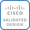
Figure 1 FlashStack System Components
All components are connected and configured according to best practices of both Cisco and Pure Storage and provide the ideal platform for running a variety of enterprise workloads with confidence. FlashStack can scale up for greater performance and capacity (adding compute, network, or storage resources individually as required), or it can scale out for environments that require multiple consistent deployments.
The validated reference architecture leverages the Pure Storage FlashArray//X, Cisco Nexus 9300 series and Cisco MDS 9700 series for the switching element as well as Cisco 6400 Series Fabric Interconnects for System Management. The FlashStack architecture (Figure 1) can maintain consistency at scale. Each of the Cisco or Pure Storage component families shown offer platform and resource options to scale the infrastructure up or down, while supporting the same features and functionality that are required under the configuration and connectivity best practices of FlashStack.
The validation tests confirm the functionality and resilience of the whole solution include the Linux operating systems SUSE Linux Enterprise Server (SLES) for SAP Applications and Red Hat Enterprise Linux (RHEL) for SAP Solutions.
FlashStack Solution Benefits
FlashStack provides a jointly supported solution by Cisco and Pure Storage. Bringing a carefully validated architecture built on superior compute, world class networking, and the leading innovations in all flash storage.
The portfolio of validated offerings from FlashStack includes, but is not limited to the following:
Streamlined operations
· Stateless architecture provides the ability to deploy VDI, Oracle database, exchange environment, SAP HANA or other application instances.
· SAP HANA Tailored Data Center Integration (TDI) certification supports the re-use of components in SAP environments. SAP HANA appliance simplicity with TDI flexibility
· Pure Storage Copy Automation tool (CAT) for SAP quickly and efficiently automates the entire SAP database copy, clone and refresh processes
· ActiveCluster™ and Purity Protect for SAP; seamless management, backup, restore and recovery across dispersed systems with almost zero performance penalty
· Cisco Intersight ready; cloud-based IT operations management simplifies SAP environments
Flexible growth
· Repeatable through Cisco UCS high-density, modular, policy-based computing platform
· Scales seamlessly from 5.5TB to more than 1.5 PB of storage capacity on premise
· Dynamic Tiering for SAP HANA allows for less frequently used data to be moved from the in-memory SAP HANA database into extended storage
· Evergreen Storage Service provides a cloud-like consumption model for on-premise storage
· Support both, Fibre Channel and Small Computer System Interface over IP (iSCSI) block storage protocols
Enterprise Grade Resiliency
· Highly available architecture and redundant components
· Non-disruptive operations
· Native data protection and business continuity : snapshots and replication
· SAP Native Storage Extension (NSE) for SAP HANA with SCM
· AppDynamics SAP Application Performance Monitoring
Cisco and Pure Storage have also built a robust and experienced support team focused on FlashStack solutions, from customer account and technical sales representatives to professional services and technical support engineers. The support alliance between Pure Storage and Cisco gives customers and channel services partners direct access to technical experts who collaborate with cross vendors and have access to shared lab resources to resolve potential issues.
This section provides a technical overview of the compute, network, storage and management components in this solution. For additional information on any of the components in this section refer to Solution References.
Cisco Unified Computing System
Cisco UCS is a data center platform that integrates computing, networking, storage access, and virtualization resources into a cohesive system designed to reduce total cost of ownership and increase business agility. The system integrates a low-latency, lossless Ethernet unified network fabric with enterprise-class, x86-architecture servers. The system is an integrated, scalable, multi-chassis platform with a unified management domain for managing all resources.
Cisco Unified Computing System consists of the following subsystems:
· Compute - The compute piece of the system incorporates servers based on the 2nd Generation Intel® Xeon® Scalable processors. Servers are available in blade and rack form factor, managed by Cisco UCS Manager.
· Network - The system integrates a low-latency, lossless 10/25/40 Gigabit Ethernet unified network fabric. Networks for LAN, SAN and management access are consolidated within the fabric. The unified fabric uses the innovative Single Connect technology to lower costs by reducing the number of network adapters, switches, and cables. This in turn lowers the power and cooling requirements of the system.
· Virtualization - The system unleashes the full potential of virtualization by enhancing the scalability, performance, and operational control of virtual environments. Cisco security, policy enforcement, and diagnostic features are now extended into virtual environments to support evolving business needs. Also, Cisco Intersight Workload Optimizer provides the visibility, real-time analytics and automation needed to optimize the IT infrastructure and deliver application performance.
· Storage access – Cisco UCS servers provide consolidated access to both SAN storage and Network Attached Storage (NAS) over the unified fabric. With storage access unified, Cisco UCS can access storage over Ethernet, Fibre Channel, Fibre Channel over Ethernet (FCoE) and Small Computer System Interface over IP (iSCSI) protocols. This capability provides customers with storage choices and investment protection. Also, the server administrators can pre-assign storage-access policies to storage resources, for simplified storage connectivity and management leading to increased productivity.
· Management: The system uniquely integrates compute, network and storage access subsystems, enabling it to be managed as a single entity through Cisco UCS Manager software. Cisco UCS Manager increases IT staff productivity by enabling storage, network, and server administrators to collaborate on Service Profiles that define the desired physical configurations and infrastructure policies for applications. Service Profiles increase business agility by enabling IT to automate and provision resources in minutes instead of days. In addition, Cisco Intersight provides the benefits of SaaS management and proactive support for Cisco UCS and Pure Storage FlashArray//X.
Cisco UCS Differentiators
Cisco Unified Computing System have revolutionized the way servers are managed in data center and provide several unique differentiators that are outlined below:
· Embedded Management — Servers in Cisco UCS are managed by embedded software in the Fabric Interconnects, eliminating the need for any external physical or virtual devices to manage the servers.
· Unified Fabric — Cisco UCS uses a wire-once architecture, where a single Ethernet cable is used from the FI from the server chassis for LAN, SAN and management traffic. Adding compute capacity does not require additional connections. This converged I/O reduces overall capital and operational expenses.
· Combined Rack and Blade Server Management — The Cisco UCS management portfolio is hardware form factor agnostic and can manage both blade and rack servers under the same management domain.
· Auto Discovery — By simply inserting a blade server into the chassis or a rack server to the fabric interconnect, discovery of the compute resource occurs automatically without any management intervention. The combination of unified fabric and auto-discovery enables the wire-once architecture of Cisco UCS, where compute capability of Cisco UCS can be extended easily while keeping the existing external connectivity to LAN, SAN and management. Once a compute resource is discovered, it can be automatically classified to a resource pool based on policies defined which is particularly useful in cloud computing.
· Model based Management Architecture — Cisco UCS Manager architecture and management database is model based, and data driven. An open XML API is provided to operate on the management model which enables easy and scalable integration of Cisco UCS Manager with other management systems.
· Service Profiles and Stateless Computing — A service profile as logical representation of a server, carries its various identities and policies. This logical server can be assigned to any physical compute resource as far as it meets the resource requirements. Stateless computing enables procurement of a server within minutes, which used to take days in legacy server management systems.
· Built-in Multi-Tenancy Support — The combination of a profiles-based approach using policies, pools and templates and policy resolution with organizational hierarchy to manage compute resources makes Cisco UCS Manager inherently suitable for multi-tenant environments, in both private and public clouds.
· Cisco UCS Manager - Automates and simplifies the management of Cisco UCS and Cisco Hyperflex infrastructure and works seamlessly with Cisco Intersight, a SaaS system management platform.
Cisco UCS Manager
Cisco UCS Manager (UCSM) provides unified, integrated management for all software and hardware components in Cisco UCS. Using Cisco Single Connect technology, it manages, controls, and administers multiple chassis for thousands of virtual machines. Administrators use the software to manage the entire Cisco Unified Computing System as a single logical entity through an intuitive graphical user interface (GUI), a command-line interface (CLI), or through a robust application programming interface (API).
Cisco UCS Manager is embedded into the Cisco UCS Fabric Interconnects using a clustered, active-standby configuration for high availability. The manager gives administrators a single interface for performing server provisioning, device discovery, inventory, configuration, diagnostics, monitoring, fault detection, auditing, and statistics collection.
Cisco UCS management software provides a model-based foundation for streamlining the day-to-day processes of updating, monitoring, and managing computing resources, local storage, storage connections, and network connections. By enabling better automation of processes, Cisco UCS Manager allows IT organizations to achieve greater agility and scale in their infrastructure operations while reducing complexity and risk.
Cisco UCS Manager provides an easier, faster, more flexible, and unified solution for managing firmware across the entire hardware stack than traditional approaches to server firmware provisioning. Using service profiles, administrators can associate any compatible firmware with any component of the hardware stack. After the firmware versions are downloaded from Cisco, they can be provisioned within minutes on components in the server, fabric interconnect, and fabric extender based on the required network, server, and storage policies for each application and operating system. The firmware’s auto-installation capability simplifies the upgrade process by automatically sequencing and applying upgrades to individual system elements.
Some of the key elements managed by Cisco UCS Manager include:
· Cisco UCS Integrated Management Controller (IMC) firmware
· RAID controller firmware and settings
· BIOS firmware and settings, including server universal user ID (UUID) and boot order
· Converged network adapter (CNA) firmware and settings, including MAC addresses and worldwide names (WWNs) and SAN boot settings
· Virtual port groups used by virtual machines, using Cisco Data Center VM-FEX technology
· Interconnect configuration, including uplink and downlink definitions, MAC address and WWN pinning, VLANs, VSANs, quality of service (QoS), bandwidth allocations, Cisco Data Center VM-FEX settings, and Ether Channels to upstream LAN switches
Cisco UCS Manager provides end-to-end management of all the devices in the Cisco UCS domain it manages. Devices that are uplinked from the fabric interconnect must be managed by their respective management applications. Cisco UCS Manager works seamlessly with Cisco Intersight, a SaaS systems management platform. It helps you achieve even greater efficiencies.
Cisco Intersight
Cisco Intersight is Cisco’s new systems management platform that delivers intuitive computing through cloud-powered intelligence. This platform offers a more intelligent management level and enables IT organizations to analyze, simplify and automate their IT environments in ways that were not possible with prior generations of tools. This capability empowers organizations to achieve significant savings in Total Cost of Ownership (TCO) and to deliver applications faster to support new business initiatives.
The Cisco UCS platform uses model-based management to provision servers and fabric automatically, regardless of form factor. Cisco Intersight works in conjunction with Cisco UCS Manager and the Cisco Integrated Management Controller (IMC). By simply associating a model-based configuration with a resource through service profiles, your IT staff can consistently align policy, server personality, and workloads. These policies can be created once and used by IT staff with minimal effort to deploy servers. The result is improved productivity and compliance and lower risk of failures due to inconsistent configuration.
Cisco Intersight will be integrated with data center, hybrid cloud platforms and services to securely deploy and manage infrastructure resources across data center and edge environments. In addition, Cisco and Pure Storage have jointly developed the first third-party integration into Cisco Intersight to give you the ability to manage Pure products from within Cisco Intersight.
Cisco Intersight delivers unique capabilities such as:
· Integration with Cisco TAC for support and case management
· Proactive, actionable intelligence for issues and support based on telemetry data
· Compliance check through integration with Cisco’s Hardware Compatibility List (HCL)
· Enables Pure Storage FlashArray//X management capabilities using Intersight Assist
More information on Cisco Intersight is available here: Cisco Intersight – SaaS Systems Management Platform.
Cisco Intersight Workload Optimizer
Cisco AppDynamics and Cisco Intersight Workload Optimizer provide visibility and insight into application and infrastructure interdependencies and business performance. The real-time decision engine drives continuous health in the IT systems by continuously analyzing workload consumption, costs and compliance constraints and matching them to IT resources in real time to prevent performance bottlenecks.
More information is available here: https://www.cisco.com/c/dam/en/us/products/collateral/servers-unified-computing/workload-optimization-manager/intersight-workload-optimizer-so.pdf.
SAP Application Monitoring with AppDynamics
AppDynamics is an Application Performance Monitoring (APM) Platform that helps you to understand and optimize the performance of your business, from its software to infrastructure to business journeys.
The AppDynamics APM Platform enables you to monitor and manage your entire application-delivery ecosystem, from the mobile app or browser client request through your network, backend databases and application servers and more. AppDynamics APM gives you a single view across your application landscape, letting you quickly navigate from the global perspective of your distributed application right down to the call graphs or exception reports generated on individual hosts.
AppDynamics has an agent-based architecture running on the SAP application server. Once our agents are installed it gives you a dynamic flow map or topography of your application. It uses the concept of traffic lights to indicate the health of your application (green is good, yellow is slow and red indicates potential issues) with dynamics baselining. AppDynamics measures application performance based on business transactions which essentially are the key functionality of the application. When the application deviates from the baseline AppDynamics captures and provides deeper diagnostic information to help be more proactive in troubleshooting and reduce the MTTR (Mean Time To Repair).
More information is available online here: https://docs.appdynamics.com/display/SAP/SAP+Monitoring+Using+AppDynamics
Cisco UCS Service Profile
Service profiles are essential to the automation functions in Cisco UCS Manager. They provision and manage Cisco UCS systems and their I/O properties within a Cisco UCS domain. Infrastructure policies are created by server, network, and storage administrators and are stored in the Cisco UCS Fabric Interconnects. The infrastructure policies required to deploy applications are encapsulated in the service profiles templates, which are collections of policies needed for specific applications. The service profile templates are then used to create one or more service profiles, which provide the complete definition of the server. The policies coordinate and automate element management at every layer of the hardware stack, including RAID levels, BIOS settings, firmware revisions and settings, server identities, adapter settings, VLAN and VSAN network settings, network quality of service (QoS), and data center connectivity.
A server’s identity is made up of many properties such as UUID, boot order, IPMI settings, BIOS firmware, BIOS settings, RAID settings, disk scrub settings, number of NICs, NIC speed, NIC firmware, MAC and IP addresses, number of HBAs, HBA WWNs, HBA firmware, FC fabric assignments, QoS settings, VLAN assignments, remote keyboard/video/monitor etc. This long list of configuration points gives the server its identity and make it unique from every other server within the data center. Some of these parameters are kept in the hardware of the server itself (like BIOS firmware version, BIOS settings, boot order, FC boot settings, etc.) while some settings are kept on your network and storage switches (like VLAN assignments, FC fabric assignments, QoS settings, ACLs, etc.). This results in the following server deployment challenges:
· Every deployment requires coordination among server, storage, and network teams
· Need to ensure correct firmware and settings for hardware components
· Need appropriate LAN and SAN connectivity
The service profile consists of a software definition of a server and the associated LAN and SAN connectivity that the server requires. When a service profile is associated with a server, Cisco UCS Manager automatically configures the server, adapters, fabric extenders, and fabric interconnects to match the configuration specified in the service profile. Service profiles improve IT productivity and business agility because they establish the best practices of your subject-matter experts in software. With service profiles, infrastructure can be provisioned in minutes instead of days, shifting the focus of IT staff from maintenance to strategic initiatives. Service profiles enable pre-provisioning of servers, enabling organizations to configure new servers and associated LAN and SAN access settings even before the servers are physically deployed.
By abstracting these service profile settings from the physical server, the service profile can then be deployed to any physical server hardware within the Cisco UCS domain. Furthermore, service profiles can, at any time, be migrated from one physical server to another. This logical abstraction of the server personality separates the dependency of the hardware type or model and is a result of Cisco’s unified fabric model (rather than overlaying software tools on top).
Service profiles benefit both virtualized and non-virtualized environments. Workloads may need to be moved from one server to another to change the hardware resources assigned to a workload or to take a server offline for maintenance. Service profiles can be used to increase the mobility of non-virtualized servers. They also can be used in conjunction with virtual clusters to bring new resources online easily, complementing existing virtual machine mobility. Service profiles are also used to enable Cisco Data Center Virtual Machine Fabric Extender (VM‑FEX) capabilities for servers that will run hypervisors enabled for VM-FEX.
Cisco UCS has uniquely addressed these challenges with the introduction of service profiles that enables integrated, policy-based infrastructure management. Cisco UCS Service Profiles hold the DNA for nearly all configurable parameters required to set up a physical server. A set of user defined policies (rules) allow quick, consistent, repeatable, and secure deployments of Cisco UCS servers.
Cisco UCS Fabric Interconnect
The Cisco UCS Fabric interconnects (FIs) are a core part of Cisco UCS and provide a single point for connectivity and management for the entire Cisco UCS system. In an active-active pair deployment, the system’s fabric interconnects integrate all components into a single, highly available management domain controlled by Cisco UCS Manager. The fabric interconnects manage all I/O efficiently and securely at a single point, resulting in deterministic I/O latency regardless of a server or virtual machine’s topological location in the system.
The Cisco UCS Fabric Interconnect provides both network connectivity and management capabilities for the Cisco UCS B-Series Blade Servers, Cisco 5100 Series Blade Server Chassis and C-Series Rack Servers. All servers attached to the fabric interconnects become part of a single, highly available management domain.
IO modules in the blade chassis support power supply, along with fan and blade management. They also support port channeling and, thus, better use of bandwidth. The IOMs support virtualization-aware networking in conjunction with the Fabric Interconnects and Cisco Virtual Interface Cards (VIC).
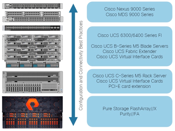
From a networking perspective, the Cisco UCS 6300 Series (Figure 2) uses a cut-through architecture, supporting deterministic, low-latency, line-rate 10 and 40 Gigabit Ethernet ports, native 4-, 8, and 16-Gbps Fibre Channel, switching capacity of 2.56 terabits per second (Tbps), and 320 Gbps of bandwidth per chassis, independent of packet size and enabled services. The product family supports Cisco® low-latency, lossless 10 and 40 Gigabit Ethernet unified network fabric capabilities, which increase the reliability, efficiency, and scalability of Ethernet networks.
Figure 2 Front view Cisco UCS 6332-16UP Fabric Interconnect
Refer to the Cisco UCS 6300 Series Fabric Interconnect Data Sheet for additional information.
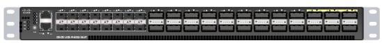
Alternatively, the 4th generation Cisco UCS 6454 Fabric Interconnect (Figure 3) offers line-rate, low-latency, lossless 10/25/40/100 Gigabit Ethernet, Fibre Channel over Ethernet (FCoE), and 32 Gigabit Fibre Channel functions. The one-rack-unit (1RU) Fabric Interconnect can be managed through Cisco Intersight and offers additional 14 physical ports compared to the 3rd generation FI. It provides a switching capacity of 3.82 Tbps and 200 Gbps of bandwidth per chassis, independent of packet size and enabled services.
Figure 3 Front view Cisco UCS 6454 Fabric Interconnect
Refer to the Cisco UCS 6400 Series Fabric Interconnect Data Sheet for additional information.
Both fabric interconnects support multiple traffic classes over a lossless Ethernet fabric from the server through the fabric interconnect. Significant TCO savings can be achieved with an FCoE optimized server design in which network interface cards (NICs), host bus adapters (HBAs), cables, and switches can be consolidated.
Cisco UCS Fabric Extender
The Cisco UCS Fabric extenders (FEX) or I/O Modules (IOMs) connects the I/O fabric between the Cisco UCS Fabric Interconnect and the Cisco UCS 5100 Series Blade Server Chassis, enabling a lossless and deterministic converged fabric to connect all blades and chassis together. Because the fabric extender is like a distributed line card, it does not perform any switching and is managed as an extension of the fabric interconnects. This approach removes switching from the chassis, reducing overall infrastructure complexity and enabling Cisco UCS to scale to up to 20 chassis without multiplying the number of switches and cabling needed, reducing TCO, and allowing all chassis to be managed as a single, highly available management domain.
In discrete mode, each server is pinned to a dedicated FEX link connected to one port of the fabric interconnect. If this link goes down, the server’s connection through this link goes down as well. In port channel mode, the server network traffic is distributed across all available links connected to multiple ports of the fabric interconnect. If one link goes down, network traffic will be re-distributed instead of being disconnected. Therefore, the port channel mode is the preferred deployment option for the FlashStack design.
The design supports two different Fabric Extender with the 6454 Fabric Interconnect and final choice depends on a scaling and bandwidth considerations for single stream network connectivity. If larger single stream network connectivity is required, for example to run backups over Ethernet or when attaching nearline storage the 40G ports of the Cisco UCS 2304XP FEX might be better suited compared to the 10G ports of the Cisco UCS 2408 FEX.
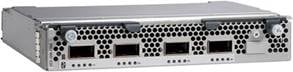
Cisco UCS 2304XP Fabric Extender
The Cisco UCS 2304 FEX has four 40 Gigabit Ethernet, FCoE-capable, Quad Small Form-Factor Pluggable (QSFP+) ports that connect the blade chassis to the Cisco UCS 6332-16UP or Cisco UCS 6454 fabric interconnect. Each Cisco UCS 2304 has four 40 Gigabit Ethernet ports connected through the midplane to each half-width slot in the chassis. Typically configured in pairs for redundancy, two fabric extenders provide up to 320 Gbps of I/O to the chassis.
Cisco UCS 2408 Fabric Extender
The Cisco UCS 2408 FEX has eight 25-Gigabit Ethernet, FCoE-capable, Small Form-Factor Pluggable (SFP28) uplink ports that connect the blade chassis to the Cisco UCS 6454 fabric interconnect. Each Cisco UCS 2408 provides 10-Gigabit Ethernet ports connected through the midplane to each half-width slot in the chassis, giving it a total 32 10G downlink interfaces to UCS blades. Typically configured in pairs for redundancy, two fabric extenders provide up to 400 Gbps of I/O from FI 6454's to 5108 chassis.
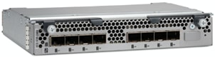
Each FEX connects to one Cisco UCS 6454 FI with multiple 25Gbps links - the number of links, which is 1, 2, 4 or 8, determines the uplink I/O bandwidth through the FEX. These links can be deployed either as independent links (discrete mode) or as group using link aggregation (port channel mode).
![]() The Cisco UCS 2408 Fabric Extender supports both, the Cisco UCS 1300 and 1400 series virtual interface cards.
The Cisco UCS 2408 Fabric Extender supports both, the Cisco UCS 1300 and 1400 series virtual interface cards.
Refer to the Cisco UCS 2408 Fabric Extender Data Sheet for additional information.
Cisco UCS 5100 Series Blade Server Chassis
The Cisco UCS 5100 Series Blade Server Chassis is a fundamental building block of the Cisco Unified Computing System, delivering a scalable and flexible blade server architecture. The Cisco UCS blade server chassis uses an innovative unified fabric with fabric-extender technology to lower TCO by reducing the number of network interface cards (NICs), host bus adapters (HBAs), switches, and cables that need to be managed, cooled, and powered. This simplicity eliminates the need for dedicated chassis management and allows scalability up to 20 chassis per Cisco UCS domain without adding complexity.
The 6-RU chassis can house up to 8 x half-width or 4 x full-width Cisco UCS B-series blade servers. A passive backplane provides support for up to 80Gbps of I/O bandwidth for each half-width blade and up to 160Gbps for each full width-blade. The rear of the chassis contains two I/O bays to house a pair of Cisco UCS 2000 Series Fabric Extenders to enable uplink connectivity to FIs for both redundancy and bandwidth aggregation.
Figure 4 Cisco UCS 5108 Blade Server Chassis Front and Rear View
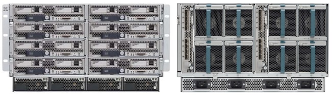
Additional information and references are available from the Cisco UCS 5108 Blade Server Chassis web page.
Cisco UCS B-Series Blade Servers
Cisco UCS B-Series Blade Servers are based on Intel® Xeon® processors. They work with virtualized and non-virtualized applications to increase performance, energy efficiency, flexibility, and administrator productivity. The Cisco UCS B-Series M5 Blade Server support the first and second-generation Intel® Xeon® Scalable processors. The second-generation Intel Cascade Lake processors introduces support for Intel® Optane DC Persistent Memory Modules (DCPMM). The UCS B-Series are workload agnostic and support both, bare-metal and virtualized workloads.
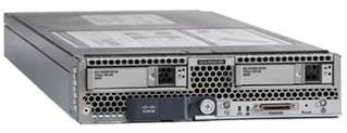
Cisco UCS B200 M5 Servers
The enterprise-class Cisco UCS B200 M5 Blade Server extend the Cisco UCS portfolio in a half-width blade form-factor. The blade server supports up to 3 terabytes (TB) of DDR4 memory. With the second-generation Intel® Xeon® Scalable processors and a mixed memory configuration with Intel® Optane DCPMM and DDR4 memory modules, the non-volatile memory technology can extend the total amount of memory up to a maximum of 7.5 TB using 12x128G DDR4 DIMMs and 12x512G Intel® Optane DCPMM.
Additionally, it offers two drives (SSD, HDD or NVMe), up to two optional NVIDIA GPUs and 80Gbps of total I/O to each server. One Cisco Virtual Interface Card (VIC) 1340 modular LAN on Motherboard (mLOM) adapter provides 40Gb FCoE connectivity to the unified fabric.
Figure 5 Cisco UCS B200 M5 Blade Server
Cisco UCS B480 M5 Servers
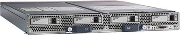
The enterprise-class Cisco UCS B480 M5 Blade Server delivers market-leading performance, versatility, and density without compromise for memory-intensive mission-critical enterprise applications and virtualized workloads, among others. The Cisco UCS B480 M5 is a full-width blade server supported by the Cisco UCS 5108 Blade Server Chassis.
The full-width Cisco UCS B480 M5 Blade Server supports two or four Intel® Xeon® Scalable CPUs. These B480 M5 servers support a maximum of 12 terabytes (TB) of DDR4 memory or 18 TB using 24x256G DDR4 DIMMs and 24x512G Intel® Optane DCPMM nonvolatile memory technology.
Additionally, it supports five mezzanine adapters and up to four optional NVIDIA GPUs, one Cisco UCS Virtual Interface Card (VIC) 1340 modular LAN on Motherboard (mLOM) and a dual-port 40-Gbps Ethernet Cisco UCS Virtual Interface Card (VIC) 1380. It will support the upcoming 4th generation VIC card as well.
Figure 6 Cisco UCS B480 M5 Blade Server
Cisco UCS C-Series Rack Servers
Cisco UCS C-Series Rack Servers are based on Intel® Xeon® processors. They work with virtualized and non-virtualized applications to increase performance, energy efficiency, flexibility, and administrator productivity. The Cisco UCS C-Series M5 Rack Server support the first and second-generation Intel® Xeon® Scalable processors. The second-generation Intel Cascade Lake processors introduces support for Intel® Optane DC Persistent Memory Modules (DCPMM).
These rack servers offers additional capabilities like the extension with PCIe cards which is not available in the Blade form factor. Examples for the usage of PCIe cards can be dedicated backup solutions or a data migration from a previous storage system. Optionally, it is possible to configure the Cisco UCS M5 C-Series in a SAP HANA appliance configuration with separate storage.
Cisco UCS C480 M5 Rack Server
The Cisco UCS C-Series Rack Servers operates either as standalone server or Cisco UCS managed to take advantage of Cisco’s standards-based unified computing innovations, including Cisco SingleConnect technology, that help drastically reduce switching and cabling requirements, reduce customers’ TCO and increase their business agility.
Cisco UCS Manager uses service profiles, templates, and policy-based management to enable rapid deployment and help ensure deployment consistency. It also enables end-to-end server visibility, management, and control in both virtualized and bare-metal environments.
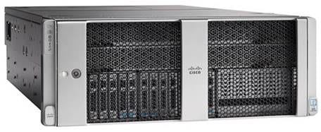
The Cisco UCS C480 M5 Rack Server (Figure 5) is a storage- and I/O-optimized enterprise-class rack server that delivers industry-leading performance for IMDBs, Big Data analytics, Virtualization workloads and bare-metal applications.
It delivers outstanding levels of expandability and performance for standalone or Cisco UCS managed environments in a 4-rack-unit (4RU) form factor, and because of its modular design, you pay for only what you need.
The Cisco UCS C480 M5 offers these capabilities:
· Latest Intel Xeon Scalable processors with up to 28 cores per socket and support for two- or four-processor configurations
· 48 DIMM slots for up to 6 TB 2933-MHz DDR4 memory or up to 18 TB in a mixed DDR4/DCPMM memory configuration
· 12 PCI Express (PCIe) 3.0 slots
· Flexible storage options with support up to 32 small-form-factor (SFF) 2.5-inch, SAS, SATA, and PCIe Non-Volatile Memory Express (NVMe) disk drives
· Cisco 12-Gbps SAS modular RAID controller in a dedicated slot
· Internal Secure Digital (SD) and M.2 boot options
· Dual embedded 10 Gigabit Ethernet LAN-on-motherboard (LOM) ports
Figure 7 Cisco UCS C480 M5 Rack Server
Cisco UCS C240 M5 Rack Server
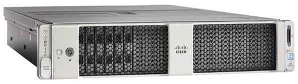
In response to ever increasing computing and data-intensive real-time workloads, the enterprise-class, 2-socket Cisco UCS C240 M5 Server (Figure 6) extends the capabilities of the Cisco UCS portfolio in a 2RU form factor offering industry-leading performance and expandability. It incorporates the Intel Xeon Scalable processors, supporting up to 20 percent more cores per socket, twice the memory capacity, and five times more NVMe PCIe SSDs than the previous generation of servers. These improvements deliver significant performance and efficiency gains that will improve your application performance. The Cisco UCS C240 M5 delivers outstanding storage expandability with exceptional performance, with:
· Latest Intel Xeon Scalable CPUs with up to 28 cores per socket
· 24 DIMMs slots for up to 3 TB 2933-MHz DDR4 memory or up to 9 TB in a mixed DDR4/DCPMM memory configuration
· Up to 26 hot-swappable SFF 2.5-inch drives, including 2 rear hot-swappable SFF drives (up to 10 support NVMe PCIe SSDs on the NVMe-optimized chassis version), or 12 large form factor (LFF) 3.5-inch drives plus 2 rear hot-swappable SFF drives
· Support for a 12-Gbps SAS modular RAID controller in a dedicated slot, leaving the remaining PCIe Generation 3.0 slots available for other expansion cards
· Modular LOM (mLOM) slot that can be used to install a Cisco UCS VIC without consuming a PCIe slot, supporting dual 10- or 40-Gbps network connectivity
· Dual embedded Intel x550 10GBASE-T LOM ports
· Modular M.2 or SD cards that can be used for bootup
· High performance for data-intensive applications
The Cisco UCS C240 M5 Rack Server is well-suited for a wide range of enterprise workloads, including; big data and analytics, collaboration, small and medium-sized business (SMB) databases, virtualization and consolidation, storage servers and high-performance appliances.
The Cisco UCS C-Series Rack Servers operates either as standalone server or Cisco UCS managed to take advantage of Cisco’s standards-based unified computing innovations, including Cisco SingleConnect technology, that help drastically reducing switching and cabling requirements, reduce customers’ TCO and increase their business agility.
Cisco UCS Manager uses service profiles, templates, and policy-based management to enable rapid deployment and help ensure deployment consistency. It also enables end-to-end server visibility, management, and control in both virtualized and bare-metal environments.
Figure 8 Cisco UCS C240 M5 Rack Server
Cisco UCS C220 M5 Rack Server
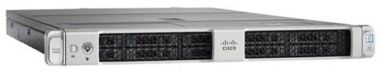
The Cisco UCS C220 M5 Rack Server (Figure 7) is among the most versatile general-purpose enterprise infrastructure and application servers in the industry. It is a high-density 2-socket rack server that delivers industry-leading performance and efficiency for a wide range of workloads, including virtualization, collaboration, and bare-metal applications.
The Cisco UCS C220 M5 server extends the capabilities of the Cisco UCS portfolio in a 1RU form factor. It incorporates the Intel Xeon Scalable processors, supporting up to 20 percent more cores per socket, twice the memory capacity, 20 percent greater storage density, and five times more PCIe NVMe SSDs than the previous generation of servers. These improvements deliver significant performance and efficiency gains that will improve your application performance. The Cisco UCS C220 M5 server delivers outstanding levels of expandability and performance in a compact package, with:
· Latest Intel Xeon Scalable CPUs with up to 28 cores per socket
· Up to 24 DDR4 DIMMs for improved performance
· Built-in support Intel Optane DCPMM nonvolatile memory technology
· Up to 10 SFF 2.5-inch drives or 4 LFF 3.5-inch drives (77 TB of storage capacity with all NVMe PCIe SSDs)
· Support for a 12-Gbps SAS modular RAID controller in a dedicated slot, leaving the remaining PCIe Generation 3.0 slots available for other expansion cards
· mLOM slot that can be used to install a Cisco UCS VIC without consuming a PCIe slot, supporting dual 10- or 40-Gbps network connectivity
· Dual embedded Intel x550 10GBASE-T LOM ports
· High performance for data-intensive applications
The Cisco UCS C220 M5 Rack Server is well-suited for a wide range of enterprise workloads beside SAP HANA, including: Big Data and analytics, Collaboration. SMB databases, Virtualization and consolidation. Storage servers, high-performance appliances.
The Cisco UCS C-Series Rack Servers operates either as standalone server or Cisco UCS managed to take advantage of Cisco’s standards-based unified computing innovations, including Cisco SingleConnect technology, that help drastically reducing switching and cabling requirements, reduce customers’ TCO and increase their business agility.
Cisco UCS Manager uses service profiles, templates, and policy-based management to enable rapid deployment and help ensure deployment consistency. It also enables end-to-end server visibility, management, and control in both virtualized and bare-metal environments.
Figure 9 Cisco UCS C220 M5 Rack Server
Cisco UCS Virtual Interface Cards (VICs)
Cisco UCS servers have various Converged Network Adapters (CNA) options. Cisco Single Connect technology unifies LAN, SAN, and systems management into one simplified link for rack servers and blade servers. This technology reduces the number of required network adapters, cables, and switches and radically simplifies the network, reducing complexity. Cisco VICs can support 256 Express (PCIe) virtual devices, either virtual Network Interface Cards (vNICs) or virtual Host Bus Adapters (vHBAs), with a high rate of I/O Operations Per Second (IOPS) and support for lossless Ethernet.
The Cisco UCS VIC 1400 series is ideally suited for next-generation networks requiring 10/25/40/100 Gigabit Ethernet for Cisco UCS C-Series and 10/40 Gigabit Ethernet connectivity for Cisco UCS B-Series servers. Cisco VICs support NIC teaming with fabric failover for increased reliability and availability. In addition, it provides a policy-based, stateless, agile server infrastructure for your data center managed through Cisco Intersight.
Cisco UCS 1440 Virtual Interface Card
The Cisco UCS VIC 1440 is a single-port 40-Gbps or 4x10-Gbps Ethernet/ Fiber Channel over Ethernet (FCoE) capable modular LAN On Motherboard (mLOM) designed exclusively for the M5 generation of Cisco UCS B-Series Blade Servers. When used in combination with an optional port expander, the Cisco UCS VIC 1440 capabilities are enabled for two 40-Gbps Ethernet ports.
Additionally, the Cisco UCS VIC 1440 supports Cisco Data Center Virtual Machine Fabric Extender (VM-FEX) technology, which extends the Cisco UCS fabric interconnect ports to virtual machines, simplifying server virtualization deployment and management.
Cisco UCS 1480 Virtual Interface Card
The Cisco UCS VIC 1480 is a single-port 40-Gbps or 4x10-Gbps Ethernet/FCoE capable mezzanine card designed exclusively for the M5 generation of Cisco UCS B-Series Blade Servers.
Additionally, the Cisco UCS VIC 1480 supports Cisco Data Center VM-FEX technology, which extends the Cisco UCS fabric interconnect ports to virtual machines, simplifying server virtualization deployment and management.
Cisco UCS 1455 Virtual Interface Card
The Cisco UCS VIC 1455 is a quad-port Small Form-Factor Pluggable (SFP28) half-height PCIe card designed for the M5 generation of Cisco UCS C-Series Rack Servers. The card supports 10/25-Gbps Ethernet or FCoE. It can present PCIe standards-compliant interfaces to the host, and these can be dynamically configured as either NICs or HBAs.
Cisco UCS 1457 Virtual Interface Card
The Cisco UCS VIC 1457 is a quad-port Small Form-Factor Pluggable (SFP28) mLOM card designed for the M5 generation of Cisco UCS C-Series Rack Servers. The card supports 10/25-Gbps Ethernet or FCoE. It can present PCIe standards-compliant interfaces to the host, and these can be dynamically configured as either NICs or HBAs.
Cisco UCS 1495 Virtual Interface Card
The Cisco UCS VIC 1495 is a dual-port Quad Small Form-Factor (QSFP28) PCIe card designed for the M5 generation of Cisco UCS C-Series Rack Servers. The card supports 40/100-Gbps Ethernet or FCoE. It can present PCIe standards-compliant interfaces to the host, and these can be dynamically configured as either NICs or HBAs.
Cisco UCS 1497 Virtual Interface Card
The Cisco UCS VIC 1497 is a dual-port Quad Small Form-Factor (QSFP28) mLOM card designed for the M5 generation of Cisco UCS C-Series Rack Servers. The card supports 40/100-Gbps Ethernet or FCoE. It can present PCIe standards-compliant interfaces to the host, and these can be dynamically configured as either NICs or HBAs.
Table 1 Supported VIC Cards for SAP HANA Certified Servers
|
|
Form Factor |
Speed |
Network Throughput |
Cisco UCS Server Compatibility |
FI Series Compatibility |
| Cisco UCS VIC 1340 |
mLOM |
40/10G |
40-80* Gbps |
Cisco UCS M5 and M4 blade servers |
6300/6400 |
| Cisco UCS VIC 1380 |
Mezz |
40/10G |
80 Gbps |
Cisco UCS M5 and M4 blade servers |
6300/6400 |
| Cisco UCS VIC 1385 |
PCIe |
40/10G |
80 Gbps |
Cisco UCS C220 M4/M5, C240 M4/M5, C460 M4, and C480 M5 rack servers |
6300/6400 |
| Cisco UCS VIC 1387 |
mLOM |
40/10G |
80 Gbps (limited by PCIe BW ~64Gbps) |
Cisco UCS C220 M4/M5 and Cisco UCS C240 M4/M5 rack servers |
6300/6400 |
| Cisco UCS VIC 1440 |
mLOM |
40/10G |
40-80* Gbps |
Cisco UCS M5 blade servers |
6300/6400 |
| Cisco UCS VIC 1480 |
Mezz |
40/10G |
80 Gbps |
Cisco UCS M5 blade servers |
6300/6400 |
| Cisco UCS VIC 1455 |
PCIe |
10/25G |
4x 10 or 25 Gbps |
Cisco UCS M5 rack servers |
6300/6400 |
| Cisco UCS VIC 1457 |
mLOM |
10/25G |
4x 10 or 25 Gbps |
Cisco UCS M5 rack servers |
6300/6400 |
| Cisco UCS VIC 1495 |
PCIe |
40/100G |
2 x 40 or 100 Gbps |
Cisco UCS M5 rack servers |
6400 |
| Cisco UCS VIC 1487 |
mLOM |
40/100G |
2 x 40 or 100 Gbps |
Cisco UCS M5 rack servers |
6400 |
* With use of Port Expander Card for the VIC 1340/1440 in the optional mezzanine slot
Additional information and references are available from the Cisco UCS VIC Data Sheets.
Cisco Nexus 9000 Series Switch
Cisco Nexus series switches provide an Ethernet switching fabric for communications between the Cisco UCS, Pure Storage FlashArray//X and the rest of a customer’s network. There are many factors to consider when choosing the main data switch in this type of architecture to support both the scale and the protocols required for the resulting applications. All Nexus switch models including the Nexus 5000 and Nexus 7000 are supported in this design and may provide additional features such as FCoE or OTV. However, be aware that there may be slightly differences in setup and configuration based on the switch used.
The Cisco Nexus 9000 Series Switches offer both modular and fixed 10/25/40/100 Gigabit Ethernet switch configurations with scalability up to 60 Tbps of non-blocking performance with less than five-microsecond latency, wire speed VXLAN gateway, bridging, and routing support.
Additional information and references are available from the Cisco Nexus 9000 Series Switches web page.
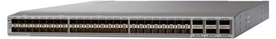
The validation for this reference design leverages the Cisco Nexus 93180YC-FX (Figure 10) in standalone Cisco NX-OS operation mode. Powered by cloud-scale technology, the Cisco Nexus 9336C-FX2 offers flexible downlink port speeds supporting 1/10/25-Gbps Ethernet or 16/32-Gbps Fibre Channel ports in a compact 1 RU form factor. The uplink port can be configured as 40 and 100-Gbps or FCoE ports, offering flexible migration options. Designed to meet the changing needs of data centers, big data applications, and automated cloud environments, this powerful switch supports both Cisco ACI and standard Cisco Nexus switch environments (NX-OS mode). This grants you access to industry-leading programmability (Cisco NX-OS) and the most comprehensive automated, policy-based, systems-management approach (Cisco ACI).
Figure 10 Cisco Nexus 93180YC-FX
Cisco MDS 9000 Series Switch
Multiprotocol storage networking is central to Cisco Unified Fabric technology. The Cisco MDS Multilayer Switches and Multilayer Directors provide a diverse range of storage networking platforms, allowing you to build a highly scalable storage network with multiple layers of network and storage management intelligence. Generally, the Fibre Channel networking devices are categorized into three classes according to the system architecture and embedded redundancy of critical components:
· Fabric switches
· Director-class switches
· Mission-critical directors
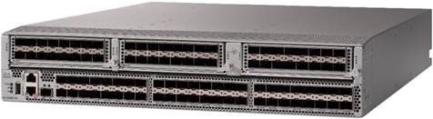
Moving from one class to the next the number of ports will increase, and the entire fabric provide greater scalability and availability. A fabric switch like the Cisco MDS 9396T (Figure 11) address the requirement for a highly scalable, virtualized, intelligent SAN infrastructure. The compact 2 RU switch provides 16/32 Gbps Fibre Channel bandwidth and provides redundancy on all major components such as the power supply and fan. The entry-level 48 ports can be expanded to 96 ports. Beyond that, a modular device is required.
Directors are more resilient and scalable than fixed SAN switches. They are modular platforms whose port count can be scaled through the addition of typically 48 ports connectivity line cards. One important benefit of a modular device is the capability to expand the director by adding specific line cards which offer a variety of interfaces and different generations of Fibre Channel ASICs. Directors offer greater availability than fabric switches because of the architectural design and duplication of components. For complete duplication, directors need to be equipped with at least two line cards.
A mission-critical director is like a director including his redundancy. However, it improves uptime by offering N+1 redundancy for the data plane and provide full operational availability even in the event of a critical failure. Despite pushing the limits toward higher port speeds, MDS 9700 Series mission-critical directors are also compatible with older equipment that customers may be reluctant to discard. In fact, MDS 9700 Series mission-critical directors are the only modular network devices in the industry that can provide port speeds starting from as low as 2-Gbps Fibre Channel and reaching all the way up to 32-Gbps Fibre Channel.
Review the Overview of Cisco Storage Networking Solutions for a quick reference guide of the different MDS Switches and Directors.
Figure 11 Cisco MDS 9396T - 32 Gbps Switch
Pure Storage FlashArray//X
Pure Storage FlashArray//X accelerates, consolidates and simplifies running business critical applications. While lowering storage spend with FlashArray//X, organizations can dramatically reduce the complexity of storage to make IT more agile and efficient.
FlashArray//X R3 provides up to 25 percent better performance than previous generations. This translates to more database transactions, faster queries and an overall improvement in the speed of business processes. If organizations have even higher performance requirements, DirectMemory™ Cache with storage-class memory provides more boost for analytical workloads.
Pure Storage FlashArray™ is a software defined, all flash block storage product catering to multiple business needs and use cases. The FlashArray product line is offered in 2 distinct classes:
· FlashArray//C - Offers exceptional block storage value and density for tier 2 workloads like snapshots, backup and more.
· FlashArray//X - The first all-flash, 100 percent NVMe storage solution designed for a range of solutions deployed on-premises.
Key differentiators of the FlashArray product line are that the storage offers an effortless experience, behaves in an efficient manner by offering deduplication and compression without a reduction in performance and offers an Evergreen™ product model to increase capacity and performance without the need to keep buying new storage products.
The Purity operating environment operates each FlashArray, the software defined solution for flash management, as well as basic and advanced software defined data services and storage API’s. The Purity operating environment offers a range of mechanisms in which effective data protection and business continuity can be implemented without additional licensing.
Some of these mechanisms are as follows:
· Full business continuity with Purity ActiveCluster™
· Multi-site replication
· Space -efficient local and remote snapshots
Pure Storage FlashArray//X is ideal for:
· Accelerating Databases and Applications. Speed transactions with consistent low latency, enable online data analytics across wide datasets, and mix production, analytics, dev/test, and backup workloads without fear.
· Virtualizing and Consolidating Workloads. Easily accommodate the most I/O-hungry Tier 1 workloads, increase consolidation rates (thereby reducing servers), simplify VI administration, and accelerate common administrative tasks.
· Delivering the Ultimate Virtual Desktop Experience. Support demanding users with better performance than physical desktops, scale without disruption from pilot to >1000’s of users, and experience all-flash performance.
· Protecting and Recovering Vital Data Assets. Provide an always-on protection for business-critical data, maintain performance even under failure conditions.
· Consistent Performance. FlashArray delivers consistent <1ms average latency. Performance is optimized for the real-world applications workloads. Full performance is maintained even under failures/updates.
· Lower Cost than Disk. Inline deduplication and compression space savings across a broad set of I/O workloads including Databases, Virtual Machines and Virtual Desktop Infrastructure.
· Mission-Critical Resiliency. FlashArray delivers >99.9999% proven availability, as measured across the Pure Storage installed base and does so with non-disruptive everything without performance impact.
· Disaster Recovery Built-In. FlashArray offers native, fully integrated data reduction-optimized backup and disaster recovery at no additional cost. Setup disaster recovery with policy-based automation within minutes. And, recover instantly from local, space-efficient snapshots or remote replicas.
· Simplicity Built-In. FlashArray offers game-changing management simplicity that makes storage installation, configuration, provisioning and migration a snap. No more managing performance, RAID, tiers or caching. Achieve optimal application performance without any tuning at any layer. Manage the FlashArray the way you like it: Web-based GUI, CLI, VMware® vCenter, Rest API, or OpenStack.
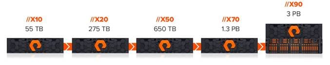
Figure 12 FlashArray//X R3 Specifications
Purity Operating Environment
Purity implements advanced data reduction, storage management and flash management features, and all features of Purity are included in the base cost of the FlashArray//X.
· Storage Software Built for Flash—Purity implements global flash management at the system level, including allocation, I/O optimization, garbage collection, and error correction. This drives 100% NVMe-connected raw flash within DirectFlash Modules and eliminates the performance-density limitations and unpredictable latency of large SSDs. Whether providing latency-optimized performance with FlashArray//X, or capacity-optimization in FlashArray//C, DirectFlash exploits the full potential of flash. It provides predictable, consistent, microsecond latency alongside higher throughput and reliability, better efficiency, and ultra-high density.
· Best Data Reduction Available—Data reduction implements five forms of inline and post-process data reduction to offer the most complete data reduction in the industry. Data reduction operates at a 512-byte aligned variable block size, to enable effective reduction across a wide range of mixed workloads without tuning.
· Highly Available and Resilient—Purity implements high availability, dual-parity RAID-HA, non-disruptive upgrades, and encryption, all of which are designed to deliver full performance to the FlashArray during any failure or maintenance event.
· Backup and Disaster Recovery Built In—Purity combines space-saving snapshots, replication, and protection policies into an end-to-end data protection and recovery solution that protects data against loss locally and globally. All functionality is fully integrated in the FlashArray and leverage native data reduction capabilities.
· SAP HANA Scale-Out deployments require a shared NFS volume across all Cisco UCS servers which are part of the SAP HANA instance. For this purpose, Windows File Services APP (also referred to as WFS APP) run on Purity and extend the FlashArray's capability to provide file services like SMB and NFS. Requirements to enable this service are a FlashArray//X20 or higher, a minimum of two 10G Ethernet ports per controller and a Domain Controller (Active Directory).
Purity//FA Pure1®
![]()
· Pure1 Manage—By combining local web-based management with cloud-based monitoring, Pure1 Manage allows you to manage your FlashArray wherever you are – with just a web browser.
· Pure1 Connect—A rich set of APIs, plugin-is, application connectors, and automation toolkits enable you to connect FlashArray//X R3 to all your data center and cloud monitoring, management, and orchestration tools.
· Pure1 Support—Pure Storage products are constantly cloud- connected, enabling Pure Storage to deliver the most proactive support experience possible. Highly trained staff combined with big data analytics help resolve problems before they start.
· Pure1 Collaborate—Extend your development and support experience online, leveraging the Pure1 Collaborate community to get peer-based support, and to share tips, tricks, and scripts.
Experience Evergreen™ Storage

Get storage that behaves like SaaS and the cloud. Deploy it once and keep expanding and improving performance, capacity, density and/or features for 10 years or more – without downtime, performance impact, or data migrations. Our “Right Size” capacity guarantee ensures you get started knowing you will have the effective capacity you need. And our Capacity Consolidation program keeps your storage modern and dense as you expand. With Evergreen Storage, you will never re-buy a TB you already own.
The section describes the SAP HANA® Tailored Data Center Integration (TDI) system requirements defined by SAP and the FlashStack for SAP HANA architecture.
SAP HANA Tailored Data Center Integration
Cisco provides SAP HANA appliance Scale-Up deployments based on Cisco UCS C-Series Servers and Cisco provided storage. While there is an advantage of having a pre-configured, pre-tested and certified SAP HANA Scale-Up infrastructure this setup doesn’t scale. SAP increases flexibility and provides an alternative to SAP HANA appliances with SAP HANA TDI, including many kinds of virtualization, network and storage technology options.
Instead of having multiple distributed environments with separate storage each it is possible to consolidate the storage requirements for the whole SAP landscape including SAP application servers to a single, central and performant FlashArray//X. Central server management through Cisco UCSM or Cisco Intersight simplifies daily operations, multiprotocol storage networking can be consolidated and network orchestrated.
While it crucial to understand the limits and requirements of an SAP HANA TDI environment, the FlashStack for SAP HANA TDI solution is a Cisco validated and tested setup based on SAP HANA certified hardware which can be viewed like an SAP HANA appliance. Previous Cisco UCS M4/M5 server-based HANA deployments can be migrated to FlashStack re-using the Cisco UCS server.
SAP provides documentation around SAP HANA TDI environments that explain the five phases of SAP HANA TDI as well as the hardware and software requirements for the entire stack in the SAP HANA TDI frequently asked questions document.
The SAP HANA Hardware and Cloud Measurement Tool (HCMT) helps to measure and analyze the hardware design and ensures the SAP HANA deployment meets the desired system and performance requirements defined by SAP. Specific SAP HANA hardware certifications are required for the compute and storage component of the FlashStack solution listed in the SAP portal for the Pure Storage FlashArray//X R3 enterprise storage as well as for the Cisco UCS B- and C-Series Servers.
SAP HANA Design Considerations
Multiple implementation options are available specific to the SAP HANA TDI integration. The focus of this reference architecture are non-virtualized SAP HANA environments.
SAP HANA System on a Single Node (Scale-Up)
The SAP HANA Scale-Up solution is the simplest installation type. In general, this solution provides the best SAP HANA performance. All data and processes are located on the same server and do not require additional network considerations when it comes to internode communication for example. This solution requires a standalone Cisco UCS B- or C-Series Server part of the FlashStack solution.
The network requirements for this option depend on the client and application access and storage connections. If a dedicated system replication or backup network is not required, a 10 GbE (access) network and an 8 Gbps Fibre channel storage connection to access the SAP HANA data, log and shared filesystem are satisfactory to operate a single SAP HANA instance in a Scale-Up configuration.
Within this architecture a single FlashArray//X10 serves up to 14 active SAP HANA nodes. The largest FlashArray//X90 storage can serve up to 44 active SAP HANA nodes per single storage array.
SAP HANA System on Multiple Nodes (Scale-Out)
While an SAP HANA Scale-Up environment is the preferred installation method it will be necessary to distribute the SAP HANA database to multiple nodes if the amount of main memory doesn’t fit to keep the SAP HANA database in memory. Multiple, independent servers are combined to form one SAP HANA system and distribute the load among multiple servers.
In a distributed system, typically each index server is assigned to its own host to achieve maximum performance. It is possible to assign different tables to different hosts (partitioning the database), or a single table can be split across hosts (partitioning of tables). SAP HANA comes with an integrated high availability option, and single servers can be configured as standby hosts.
The Fibre Channel storage LUNs are mapped to the SAP HANA servers with a point-to-point connection. In the event of a failover to the standby host, the remapping of the logical volumes is managed by the SAP HANA Storage Connector API. SAN LUNs appear to the Operating System as disks. For shared SAP HANA binaries NFS storage is required. Redundant connectivity to the corporate network via LAN (Ethernet) and to the storage via the Storage Area network (SAN) must always be configured.
The network requirements for this deployment option are higher than for Scale-Up HANA systems. In addition to the client and application access and Fibre channel SAN, the Scale-Out environment require a node-to-node network as well as an NFS network towards the FlashArray//X20 or higher. Without separate system replication or backup network connection the minimum connectivity requirements are:
· 10GbE (access) network
· 10GbE NFS (HANA shared) network
· 10GbE (node-to-node) network
· 16 Gb Fibre channel storage connection
Within this architecture a single FlashArray//X20 serves up to 22 active SAP HANA worker nodes. The largest FlashArray//X90 R3 storage can serve up to 44 active SAP HANA nodes per single storage array. The maximum amount of active SAP HANA nodes in a Scale-Out SAP HANA configuration is limited by SAP to 16 active SAP HANA servers.
Hardware Requirements for the SAP HANA Database
Hardware and software requirements to run SAP HANA systems are defined by SAP. This Cisco Validated Design uses guidelines provided by SAP.
CPU
The Cisco UCS Manager Release 4.0(4) introduce support for the second-generation Intel® Xeon® Scalable processors (Cascade Lake) CPUs. The Cisco UCS B480 M5 and Cisco UCS C480 M5 servers are capable to be configured with full or half size amount of Intel Xeon scalable family CPUs. The 28 cores per CPU Intel Xeon Platinum 8276 or 8280 CPUs are certified for SAP HANA environments.
Memory
The Cisco Integrated Management Controller (IMC) and Cisco UCS Manager Release 4.0(4) introduce support for Intel® Optane™ Data Center persistent memory modules (DCPMM) on Cisco UCS M5 servers based on the Second-Generation Intel ® Xeon® Scalable processors (Cascade Lake).
The Cisco UCS M5 servers can operate either with DDR4 DIMM memory only or starting with SAP HANA 2.0 SPS03 revision 35+ in various memory capacity ratios in a mixed Intel Optane DCPMM and DRAM DIMMs memory configuration. The Cisco UCS M5 server will not function without any DRAM DIMMs installed.
Intel Optane DCPMM will be used for the column store data of the SAP HANA database only. Appropriate SAP HANA memory sizing must be performed before considering an Intel Optane DCPMM configuration. Detailed information on the configuration and management is available in the whitepaper Cisco UCS: Configuring and Managing Intel Optane Data Center Persistent Memory Modules.
In DDR4 DIMM memory only population the following configuration rules apply:
· Homogenous symmetric assembly of dual in-line memory modules (DIMMs) for example, DIMM size or speed should not be mixed
· Maximum use of all available memory channels
· Maximum supported Memory Configuration
· Cisco UCS B200 M5 servers with 2 CPUs support up to 1.5TB for SAP Business Warehouse (BWoH/BW4HANA) and up to 3TB for SAP Business Suite (SoH/S4HANA)
· Cisco UCS B480 M5 Servers with 4 CPUs support up to 3TB for SAP Business Warehouse (BWoH/BW4HANA) and up to 3TB for SAP Business Suite (SoH/S4HANA)
In Intel Optane DCPPM/DDR4 DIMM mixed memory population the following rules apply:
· The installed DDR4 DIMMs must all be the same size
· The installed DCPMMs must all be the same size
· Balanced memory population and maximum use of all available memory channels
· Maximum supported Memory Configuration
· Cisco UCS B200 M5 Servers with 2 CPUs support up to 7.5 TB for SAP Business Suite (SoH/S4HANA)
· Cisco UCS B480 M5 Servers with 4 CPUs support up to 18 TB for SAP Business Suite (SoH/S4HANA)
Network
An SAP HANA data center deployment can range from a database running on a single host to a complex distributed system. Distributed systems can get complex with multiple hosts located at a primary site having one or more secondary sites; supporting a distributed multi-terabyte database with full fault and disaster recovery.
SAP HANA has different types of network communication channels to support the different SAP HANA scenarios and setups like:
· Client zone: Different clients, such as SQL clients on SAP application servers, browser applications using HTTP/S to the SAP HANA XS server and other data sources (such as BI) need a network communication channel to the SAP HANA database. SAP recommends a 10GbE connection for the client and application server network.
· Internal zone: The internal zone covers the communication between hosts in a distributed SAP HANA system as well as the communication used by SAP HANA system replication between two SAP HANA sites. SAP recommends dedicated 10GbE network connections for the internode and replication network connection.
· Storage zone: Although SAP HANA holds the bulk of its data in memory, the data is also saved in persistent storage locations. In most cases, the preferred storage solution involves separate, externally attached storage subsystem devices capable of providing dynamic mount-points for the different hosts, according to the overall landscape. A storage area network (SAN) is used for storage connectivity. In distributed environments an additional shared NFS network is required as well.
Refer to the document SAP HANA TDI - network requirements for more details and sizing recommendations.
Storage
SAP HANA is an in-memory database which uses storage devices to save a persistent copy of the data for the purpose of startup and fault recovery without data loss. The choice of the specific storage technology is driven by various requirements like size, performance and high availability. All FlashArray//X storage arrays are certified as SAP HANA certified Enterprise Storage.
SAP Landscape Sizing
FlashStack for SAP HANA TDI is capable to run the whole SAP landscape in one solution. Nevertheless, hardware requirements to run the landscape, such as memory, CPU power, disk space, I/O capacity and network bandwidth requirements needs to be determined. The SAP Standard Application Benchmark and its SAP Quick Sizer tool helps to find the appropriate hardware configuration in conjunction with the Sales and Distribution (SD) Benchmark.
SAP HANA database bare metal installations can run along with virtualized SAP application workloads which are common in the datacenter. Virtualization of the SAP HANA database brings additional rules and limitations like a limit of 224 vCPUs or a 2TB memory limit for BW Scale-Out solutions. SAP note 2393917 summarizes the current support status for SAP HANA with vSphere.
The FlashArray//X provides 100% of the required performance with a single data pack of NVME SSDs. Additional data packs are about capacity. The recommended, minimum disk space requirements for SAP HANA TDI installations are for SAP HANA Scale-Up configurations approximately 2,5 times of the main memory and for SAP HANA Scale-Out configurations 1,5 times the main memory + one times main memory for every 4 active SAP HANA nodes. The SAP quick sizer report provides detailed information on the required persistent storage capacity per SAP HANA instance.
To summarize hosting multiple Scale-Up and Scale-Out systems and additional SAP application servers requires proper sizing of the infrastructure with a clear compute node to storage system ratio. The number of compute nodes per FlashArray//X must be determined based on the total number of active SAP HANA nodes in the SAP system landscape and involves corresponding scaling of the associated compute and storage gear as well as the networking components based on port availability and usage.
Operating System
The minimum supported operating system versions for the second-Generation Intel ® Xeon® Scalable processors (Cascade Lake) and the SAP HANA platform are as follows:
· SUSE Linux Enterprise Server for SAP Applications 12 SP4
· Red Hat Enterprise Linux 7.6 for SAP Solutions
The current Linux versions at the point in time when this design guide was published are SLES for SAP 15 SP1 and RHEL 8.1 for SAP Solutions. Please refer to SAP Note 2235581 - SAP HANA: Supported Operating Systems to find the minimum SAP HANA revision supported with the operating system of your choice.
High Availability
The infrastructure for any SAP HANA solution must not have a single point of failure. To support high availability, the hardware and software requirements are:
· External storage: Redundant data paths, dual controllers, and a RAID-based configuration
· Ethernet switches: Two or more independent switches
· Storage network switches: Two or more independent switches
SAP HANA comes with an integrated high-availability function. If the SAP HANA system is configured with an additional standby host, a failed SAP HANA worker node will start on the stand-by node automatically. For automatic host failover the storage connector API must be properly configured during the installation of the SAP HANA platform.
Although not tested and validated in this design additional high-availability solutions like SAP HANA System Replication with Linux Cluster are available as well.
For detailed information from SAP, refer to SAP HANA Administration Guide - High Availability for SAP HANA or SAP HANA Administration Guide – Configuring SAP HANA System Replication.
Physical Topology
FlashStack for SAP HANA TDI provides an end-to-end architecture with Cisco hardware and Pure Storage that demonstrates support for multiple SAP HANA workloads with high availability and secure multi-tenancy. The architecture uses Cisco UCS managed Cisco UCS Servers and Cisco UCS Fabric Interconnects. The uplink from the Cisco UCS Fabric Interconnect connect to Nexus 9000 family switches with high availability and failover functionality. The Ethernet traffic and uplink to customer network is handled by the Cisco Nexus switches. The storage traffic between the servers and the FlashArray//X flows through Cisco UCS Fabric Interconnect and Cisco MDS switching components.
Figure 13 Physical Topology of a FlashStack for SAP HANA TDI solution
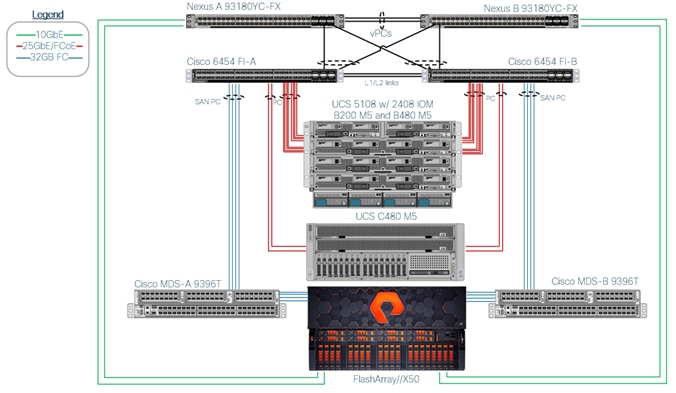
Validated components of this converged architecture are:
· Cisco Nexus 93180YC-FX – 100 Gb capable, LAN connectivity to the Cisco UCS compute resources.
· Cisco UCS 6454 Fabric Interconnect – Unified management of Cisco UCS compute, and the compute’s access to storage and networks.
· Cisco UCS 2408 FEX - 25GB Ethernet, FCoE capable uplink ports from the 5108 chassis to the fabric interconnect.
· Cisco UCS B200 M5 – High powered, versatile blade server with two CPUs for SAP HANA TDI.
· Cisco UCS B480 M5 – High powered, versatile blade server with four CPUs for SAP HANA TDI.
· Cisco UCS B480 M5 - Mixed memory configuration with Intel Optane DCPM and DDR4 modules.
· Cisco MDS 9706 Director - 32 Gbps capable Fibre Channel connectivity within the architecture, as well as interfacing to resources present in an existing data center.
· FlashStack//X50 – Mid-range, high performance all-flash storage system.
· Cisco UCS Manager/Cisco Intersight – Management delivered through the Fabric Interconnect, providing stateless compute, and policy driven implementation of the servers managed by it.
Examples for alternative components of the architecture are:
· Cisco UCS 6332-16UP Fabric Interconnect - Unified management of Cisco UCS compute, and the compute’s access to storage and networks.
· Cisco UCS 2304 FEX - 40GB Ethernet, FCoE capable uplink ports from the 5108 chassis to the fabric interconnect.
· Cisco MDS 9396T – 32 Gbps capable Fiber Channel connectivity within the architecture, as well as interfacing to resources present in an existing data center.
· Cisco UCS C220/C240/C480 M5 Rack Mount Server - Managed through Cisco UCSM with single wire management, using 10/25/40/100G uplinks to the fabric interconnect.
Scale and Performance Consideration
Although this is the base validated design, each of the components can be scaled easily to support specific business requirements. Additional chassis for blade servers or rack mount servers increase compute capacity without additional network components.
Configuration limits with the Cisco 6454 FI are 20 chassis per Cisco UCS domain or 160 combined blade and rack servers. The FI is limited to 8 uplink port channels per fabric interconnect and each host can have up to 24 eNIC and 8 fNIC devices.
In this design, the supported Cisco UCS C-Series servers can be either directly connected to the FIs or connect though supported top-of-rack Cisco Nexus Fabric Extenders which connect to the FIs. The FlashStack design requires all servers are Cisco UCS managed in order to ensure consistent policy-based provisioning, stateless computing and uniform management of the server resources, independent of the form-factor.
Compute Connectivity
Each compute chassis in the design is connected to the managing fabric interconnect with a minimum of two 25GbE ports per IOM. Ethernet traffic from the upstream network and Fiber Channel frames from the FlashArray//X are converged within the fabric interconnect to be both Ethernet and Fiber Channel over Ethernet transmitted to the Cisco UCS servers through the IOM. The converged Ethernet and FCoE traffic are configured as port channels with the specification of a Chassis/FEX Discovery Policy within UCSM.
Network Connectivity
The network coming into each of the fabric interconnects is configured as a Port Channel to the respective fabric interconnects but is implemented as Virtual Port Channels (vPC) from the upstream Nexus switches. In the switching environment, the vPC provides the following benefits:
· Allows a single device to use a Port Channel across two upstream devices
· Eliminates Spanning Tree Protocol blocked ports and use all available uplink bandwidth
· Provides a loop-free topology
· Provides fast convergence if either one of the physical links or a device fails
· Helps ensure high availability of the network
The upstream network connecting to the Cisco UCS 6454 Fabric Interconnects utilize 10/25 Gbps unified ports to talk to the upstream Nexus switch. In this design, 25G ports were used for the construction of the port channels that connect to the vPCs.
Figure 14 Cisco UCS 6454 Fabric Interconnect Uplink Connectivity to Nexus 93180YC-FX
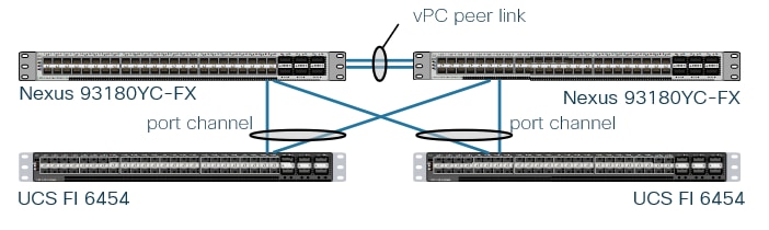
Storage Connectivity
The FlashArray//X comprise of multiple controllers that control connectivity to the fiber channel fabrics. This allows designing multiple layers of redundancy within the storage architecture, increasing availability and maintaining performance during a failure event. Each controller contains up to four individual fiber channel ports and allow redundant connections to each fabric in the Cisco UCS infrastructure.
The FlashArray//X controllers connect to the respective fabric interconnects associated through the Cisco MDS switches. For the fabric interconnects, these are configured as SAN port channels, with N_Port ID Virtualization (NPIV) enabled on the MDS. This configuration allows:
· Increased aggregate bandwidth between the fabric interconnects and the MDS
· Load balancing between the links
· High availability in the result of a failure of one or more of the links
· Resiliency to switch and/or controller failure
FlashArray//X NFS
With Pure's Purity//FA 4.10.9 or higher, it is possible to have VMware (VM) instances of a Windows Server 2016 running in each of the controllers which form a Windows Failover Cluster. Windows File Servers (WFS) are created within the cluster to serve as NFS shares.
Each WFS VM installs on its own separate boot volume and includes a default data volume to store the shared data. For Windows clustering purposes, a default quorum witness volume is exported to both WFS VMs. Subsequent data volumes can be created if additional capacity is required. Data volumes are also exported to both WFS VMs to ensure persistent data across WFS VM failovers.
Requirements for the WFS configuration:
· The FlashArray must have two 10G iSCSI services ports on each controller for cluster and file services client traffic
· Domain Controller: Microsoft Failover Cluster requires a domain controller in the environment; therefore, a working domain controller must exist in order to run WFS.
· Domain Administrator Privileges: Customers must have appropriately elevated Domain Administrator privileges in order to perform many of the required setup steps like the following:
- Configuring WFS VM IP addresses
- Creating Microsoft Failover Clusters
- Creating File Servers
· DNS Server: There must be a functional DNS server in the environment in order to run file services with WFS. The two WFS VMs, Failover Cluster, and File Servers will be given a default hostname. The hostname can be changed optionally.
· IP Addresses: A minimum of six total IP addresses are required to run WFS.
MDS Zoning
Zoning within the MDS is configured for each SAP HANA Scale-Up host with single initiator multiple target zones, leveraging the Smart Zoning feature for greater efficiency. The design implements a simple, single VSAN layout per fabric within the MDS, however configuration of differing VSANs for greater security and tenancy are supported.
For SAP HANA Scale-Out hosts the zoning configuration within the MDS changes to a multiple initiator multiple target zone and each zone includes the initiator of all SAP HANA worker hosts to ensure successful failover of the SAP HANA standby host.
Initiator (Cisco UCS hosts) and targets (FlashArray//X controller ports) are set up with device aliases within the MDS to simplify identification within zoning and flogi connectivity. The whole configuration of the zones and respective zonesets can be managed via the command line interface (CLI). However, the management is also available within the Cisco Data Center Network Manager (DCNM) for a simpler administrative experience and comprehensive network management.
More information about zoning and the Smart Zoning feature is available in section Storage Design Options.
Intersight Connectivity Requirements
All Device Connectors must resolve svc.intersight.com and allow outbound initiated HTTPS connections on port 443. If a proxy is required for an HTTPS connection to svc.intersight.com, it can be configured in the Device Connector user interface.
The Device Connector must be able to send DNS requests to a DNS server and resolve DNS records, especially svc.intersight.com to an IP address. Optionally the same DNS server can be used to run the windows file services on the FlashArray//X to provide NFS shares to the infrastructure.
In addition, all devices times need to be properly synchronized, otherwise the Device Connector may be unable to establish a secure connection to Intersight. Also, this is a requirement for the server operating system configuration to run SAP HANA Scale-Out deployments. Non-working time synchronization can lead to unexpected downtimes for SAP HANA Scale-Out environments.
For the Intersight connectivity you must configure DNS and NTP on the management interface (Cisco UCSM) and not on the Device Connector UI.
The FlashArray integration requires the download and on-premise installation of Cisco Intersight Assist Virtual Appliance in your data center. Intersight Assist acts as a proxy between all your on-premise FlashArray devices and Cisco Intersight via a single 443 SSL connection.
More information is available from the Cisco Intersight Help Center.
Architecture Design Options
Cisco UCS Server Design Options
Supporting up to 7.5 TB of memory in a half width blade format and 18 TB of memory in a full width blade or rack format Cisco UCS servers are ideal for any SAP workloads. The configuration design of these servers includes:
· Diskless SAN boot – Persistent operating system installation, independent of the physical blade for true stateless computing.
· A variety of VIC adapter cards provide different Ethernet/FCoE bandwidth, either 10, 25, 40 or 100G capable cards are available for the different Cisco UCS B- or C-Series Server.
· Cisco UCS C-Series Rack server provide the option to insert PCIe cards which might be required to connect backup environments or temporarily to attach external storage for data migration.
· SAP HANA 2.0 SPS 03 and newer supports various Intel Optane DCPMMs/DDR4 capacity ratios.
Network Design Options
Management Connectivity
Out-of-band management is handled by an independent switch that could be one currently in place in the customer’s environment. Each physical device carries its management interface through this Out-of-band switch. In-band management is carried as a differing VLAN within the solution according to the SAP HANA Network requirements.
Out-of-band configuration for the components configured as in-band can be enabled, however this requires additional uplink ports on the 6454 Fabric Interconnects if the out-of-band management is kept on a separate out-of-band switch. A disjoint layer-2 configuration allows a complete separation of the management and data plane networks. This setup requires additional vNICs on each server, which are then associated with the management uplink ports.
Jumbo Frames
Jumbo frames are a standard recommendation across Cisco designs to help leverage the increased bandwidth availability of modern networks. To take advantage of the bandwidth optimization and reduced consumption of CPU resources gained through jumbo frames, they are configured at each network level to include the virtual switch and virtual NIC.
This optimization is relevant for VLANs that stay within the pod, and do not connect externally. Any VLANs that are extended outside of the pod should be left at the standard 1500 MTU to prevent drops from any connections or devices not configured to support a larger MTU size.
Storage Design Options
Pure Storage FlashArray//X is certified as SAP HANA Enterprise Storage in SAP HANA TDI environments. The Evergreen product model allows to increase capacity and performance without the need to keep buying new storage products.
The Purity operating environment offers a range of mechanisms in which the effective data protection and business continuity can be implemented without additional licensing and allows solution designs with full business continuity with Purity ActiveCluster, multi-site replication and space efficient local and remote snapshots to just name some.
LUN Multiplicity per HBA and Different Pathing Options
This design implements Single Initiator-Multi Target (SI-MT) zoning in conjunction with single vHBAs per fabric on the Cisco UCS infrastructure. This means that each vHBA within Cisco UCS will see multiple paths on their respective fabric to each LUN. Using this design requires the use of Cisco Smart Zoning within the MDS switches.
Different pathing options including Single Initiator-Single Target (SI-ST) are supported, however it may reduce availability and performance especially during a component failure or upgrade scenario within the overall data path.
Zoning and Smart Zoning
For SAP HANA Scale-Up hosts zoning is set for single initiator (Cisco UCS host vHBA) with multiple targets (VSP controller ports) to optimize traffic intended to be specific to the host and the storage controller. Using single initiator/multiple target zoning provides reduced administrative overhead versus configuring single initiator/single target zoning, and results in the same SAN switching efficiency when configured with Smart Zoning.
For SAP HANA Scale-Out hosts zoning is set to multiple initiator with multiple targets to optimize traffic intended to be specific to the host or SAP HANA standby host and the storage controller.
Smart Zoning is configured on the MDS to allow for reduced TCAM (ternary content addressable memory) entries, which are fabric ACL entries of the MDS allowing traffic between targets and initiators. When calculating TCAMs used, two TCAM entries will be created for each connection of devices within the zone. Without Smart Zoning enabled for a zone, targets will have a pair of TCAMs established between each other, and all initiators will additionally have a pair of TCAMs established to other initiators in the zone as illustrated in Figure 15.
Figure 15 Traditional SAN Zoning
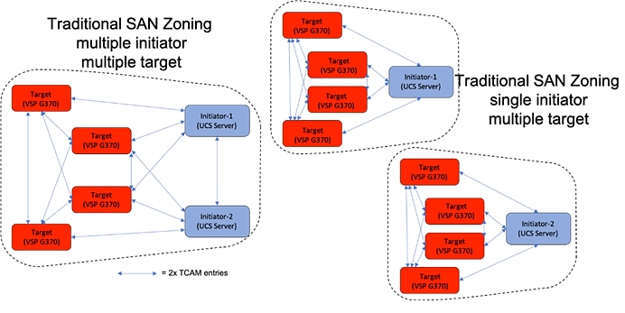
Using Smart Zoning, Targets and Initiators are identified, reducing TCAMs needed to only occur Target to Initiator within the zone as illustrated in Figure 16.
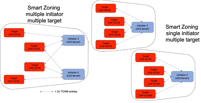
Large multiple initiator to multiple target zones can take on an exponential growth, especially without smart zoning enabled. Single initiator/single target zoning will produce the same amount of TCAM entries with or without Smart Zoning however it will match the TCAM entries used for any multiple target zoning method that is done with Smart Zoning.
Design Considerations
Cisco Nexus 9000 Series vPC Best Practices
The following Cisco Nexus 9000 design best practices and recommendations were used in this design.
· vPC Peer Keepalive Link Considerations
- It is recommended to have a dedicated 1Gbps layer 3 links for vPC peer keepalive, followed by out-of-band management interface (mgmt0) and lastly, routing the peer keepalive link over an existing Layer3 infrastructure between the existing vPC peers.
- vPC peer keepalive link should not be routed over a vPC peer-link.
- The out-of-band management network is used as the vPC peer keepalive link in this design.
· vPC Peer Link Considerations
- Only vPC VLANs are allowed on the vPC peer-links. For deployments that require non-vPC VLAN traffic to be exchanged between vPC peer switches, deploy a separate Layer 2 link for this traffic.
- Only required VLANs are allowed on the vPC peer links and member ports – prune all others to minimize internal resource consumption.
- Ports from different line cards should be used to provide redundancy for vPC peer links if using a modular switch model.
- vPC peer switches deployed using the same bridge-id and spanning tree VLAN priority by configuring the peer-switch command on both vPC peer switches. This feature improves convergence and allows peer switches to appear as a single spanning-tree root in the Layer 2 topology.
- vPC role priority specified on both Cisco Nexus peer switches. vPC role priority determines which switch will be primary and which one will be secondary. The device with the lower value will become the primary. By default, this value is 32677. Cisco recommends that the default be changed on both switches. Primary vPC devices are responsible for BPDU and ARP processing. Secondary vPC devices are responsible for shutting down member ports and VLAN interfaces when peer-links fail.
- vPC convergence time of 30s (default) was used to give routing protocol enough time to converge post-reboot. The default value can be changed using delay-restore <1-3600> and delay-restore interface-VLAN <1-3600> commands. If used, this value should be changed globally on both peer switches to meet the needs of your deployment.
- vPC peer switches enabled as peer-gateways using peer-gateway command on both devices. Peer-gateway allows a vPC switch to act as the active gateway for packets that are addressed to the router MAC address of the vPC peer allowing vPC peers to forward traffic.
- vPC auto-recovery enabled to provide a backup mechanism in the event of a vPC peer-link failure due to vPC primary peer device failure or if both switches reload but only one comes back up. This feature allows one peer to assume the other is not functional and restore the vPC after a default delay of 240s. This needs to be enabled on both switches. The time to wait before a peer restores the vPC can be changed using the command: auto-recovery reload-delay <240-3600>.
- Cisco NX-OS can synchronize ARP tables between vPC peers using the vPC peer links. This is done using a reliable transport mechanism that the Cisco Fabric Services over Ethernet (CFSoE) protocol provides. For faster convergence of address tables between vPC peers, ip arp synchronize command was enabled on both peer devices in this design.
· vPC Member Link Considerations
- LACP used for port channels in the vPC. LACP should be used when possible for graceful failover and protection from misconfigurations
- LACP mode active-active used on both sides of the port channels in the vPC. LACP active-active is recommended, followed by active-passive mode and manual or static bundling if the access device does not support LACP. Port-channel in mode active-active is preferred as it initiates more quickly than port-channel in mode active-passive.
- LACP graceful-convergence disabled on port-channels going to Cisco UCS FI. LACP graceful-convergence is ON by default and should be enabled when the downstream access switch is a Cisco Nexus device and disabled if it is not.
- Only required VLANs are allowed on the vPC peer links and member ports – prune all others to minimize internal resource consumption.
- Source-destination IP, L4 port and VLAN use load-balancing hashing algorithms for port-channels. This improves fair usage of all member ports forming the port-channel. The default hashing algorithm is source-destination IP and L4 port.
· vPC Spanning Tree Considerations
- The spanning tree priority was not modified. Peer-switch (part of vPC configuration) is enabled which allows both switches to act as root for the VLANs.
- Loopguard is disabled by default.
- BPDU guard and filtering are enabled by default.
- Bridge assurance is only enabled on the vPC Peer Link.
Test Scenarios
The following three solution scenarios are validated and tested:
· SAP HANA Scale-Up
· SAP HANA Scale-Up with Intel Optane DCPM/DDR4 memory configuration
· SAP HANA Scale-Out
All scenarios have been tested by Cisco and Pure Storage and the accompanying deployment guide provides an installation procedure for both, SUSE and Red Hat Linux, following best practices from Cisco, Pure Storage, SUSE, Red Hat and SAP. All SAP HANA TDI phase 5 requirements have been tested and passed performance metrics and high availability requirements, including:
· Cisco UCS Setup and Configuration
· FlashArray//X Setup and Configuration
· MDS Setup and Configuration
· Host Based SAN Boot
· Operating System Configuration for SAP HANA
· Installation and Configuration of SAP HANA 2.0 SPS04 Rev. 46
· Performance Tests using SAP’s Hardware Configuration Check Tool (HCMT)
Validated Hardware
Cisco UCSM, Release 4.1 provides unified, embedded management of all software and hardware components of Cisco UCS across multiple chassis and Cisco UCS servers. The unified software release for all supported Cisco UCS hardware platforms enables support for UCS 6454 Fabric Interconnects, VIC 1400 series adapter cards, the Second-Generation Intel® Xeon® Scalable processor (Cascade Lake) and Intel Optane DCPMM on Cisco UCS M5 B-Series or C-Series Servers.
Table 2 describes the hardware and software versions used during the solution validation. It is important to note that Cisco, Pure Storage, and SAP have interoperability matrixes that should be referenced to determine the solution is qualified for support. Links to this documentation are available in the Solution Reference section.
Table 2 Hardware and Software Versions used in this Solution
| Component |
Software |
|
| Network |
Nexus C93180YC-FX |
9.2(1) |
| MDS 9706 (DS-X97-SF1-K9 & DS-X9648-1536K9) |
8.3(1) |
|
| Compute |
Cisco UCS Fabric Interconnect 6454 |
4.1(1b) |
| Cisco UCS 2408 IOM |
4.1(1a) |
|
| Cisco UCS B200 M5 |
4.1(1b) |
|
| Cisco UCS B480 M5 |
4.1(1b) |
|
| Operating System |
SUSE Linux Operating System |
SLES for SAP Applications 15 SP1 |
| Red Hat Operating System |
RHEL for SAP Solutions 8.1 |
|
| Storage |
Purity//FA |
5.3.6 |
Cisco CX Services
Cisco Intersight
Cisco Intersight is a lifecycle management platform for your infrastructure. Cisco Intersight Software as a Service (SaaS) unifies and simplifies your experience of the Cisco Unified Computing System and provides enhanced capabilities including Cisco TAC integration which help you quickly respond to problems before they affect operations.
Solution Support Service
Solution Support includes both Cisco product support and solution-level support, resolving complex issues in multivendor environments, on average, 43% more quickly than product support alone. Solution Support is a critical element in data center administration, to help rapidly resolve any issue encountered, while maintaining performance, reliability, and return on investment. This service centralizes support across your multivendor Cisco environment for both our products and solution partner products you’ve deployed in your ecosystem. Whether there is an issue with a Cisco or solution partner product, just call us. Our experts are the primary point of contact and own the case from first call to resolution. For more information, go to: https://www.cisco.com/c/m/en_us/customer-experience/support/solution-support.html
Cisco and Pure Storage jointly developed FlashStack, which uses best-in-class storage, server and network components to serve as a foundation for a variety of enterprise application workloads. With a FlashStack solution, customers can leverage a secure, integrated, and optimized stack that includes compute, network, and storage resources that are sized, configured and deployed in a flexible manner.
The following factors make the combination of Cisco UCS with Pure Storage FlashArray//X so powerful for SAP environments:
· Cisco UCS stateless computing architecture provided by the Service Profile capability of Cisco UCS allows for fast, non-disruptive workload changes to be executed simply and seamlessly across the integrated Cisco UCS infrastructure and Cisco x86 servers.
· Hardware-level redundancy for all major components using Cisco UCS and Pure Storage availability features.
· Integrated, holistic system and data management across your entire infrastructure
· Pure’s evergreen model means performance, capacity and features improve over time without disruption.
FlashStack is a flexible infrastructure platform composed of pre-sized storage, networking, and server components. It is designed to ease your IT transformation and operational challenges with maximum efficiency and minimal risk.
FlashStack for SAP HANA differs from other solutions by providing:
· Integrated, validated technologies from industry leaders and top-tier software partners.
· A single platform built from unified compute, fabric, and storage technologies, allowing you to scale to large-scale data centers without architectural changes.
· Centralized, simplified management of infrastructure resources, including end-to-end automation.
· Evergreen storage so you will never pay for more storage than you need, but still have ample storage available on demand when you need it.
· A flexible Solution Support model that resolves issues rapidly and spans across infrastructure and software
Cisco Unified Computing System
Cisco Unified Computing System:
http://www.cisco.com/en/US/products/ps10265/index.html
Cisco UCS 6400 Fabric Interconnect Data Sheet:
Cisco UCS 5100 Series Blade Server Chassis:
http://www.cisco.com/en/US/products/ps10279/index.html
Cisco UCS 2400 Series Fabric Extenders:
Cisco UCS 1300 and 1400 Series VIC adapters:
http://www.cisco.com/en/US/products/ps10277/prod_module_series_home.html
Cisco UCS B-Series Blade Server:
Cisco UCS C-Series Rack Server:
Intel Optane DC Persistent Memory and SAP HANA Platform Configuration:
Cisco UCS Manager:
http://www.cisco.com/en/US/products/ps10281/index.html
Cisco Intersight:
https://www.cisco.com/c/en/us/products/servers-unified-computing/intersight/index.html
Network and Management
Cisco Nexus 9000 Series Switches:
http://www.cisco.com/c/en/us/products/switches/nexus-9000-series-switches/index.html
Cisco MDS 9000 Series Multilayer Switches:
Cisco Data Center Network Manager:
Design a Reliable and Highly Available Fibre Channel SAN (Whitepaper):
Pure Storage FlashArray//X
Pure Storage FlashArray//X series:
https://www.purestorage.com/products/flasharray-x.html
Pure Storage FlashArray//X for SAP applications:
https://www.purestorage.com/solutions/applications/sap.html
Pure Storage - SAP HANA Implementation and Best Practices:
SAP HANA
SAP HANA Platform on SAP Help Portal:
https://help.sap.com/viewer/p/SAP_HANA_PLATFORM
SAP HANA Tailored Data Center Integration Overview:
https://www.sap.com/documents/2017/09/e6519450-d47c-0010-82c7-eda71af511fa.html
SAP HANA Tailored Data Center Integration - Storage Requirements:
https://www.sap.com/documents/2015/03/74cdb554-5a7c-0010-82c7-eda71af511fa.html
SAP HANA Network Requirements:
https://www.sap.com/documents/2016/08/1cd2c2fb-807c-0010-82c7-eda71af511fa.html
Interoperability Matrixes
Cisco UCS Hardware Compatibility Matrix:
https://ucshcltool.cloudapps.cisco.com/public/
Cisco Nexus and MDS Interoperability Matrix:
Pure Storage Compatibility Matrix:
https://support.purestorage.com/FlashArray/Getting_Started_with_FlashArray/Compatibility_Matrix
FlashArray Transceiver and Cable Support:
SAP Note 2235581 - SAP HANA: Supported Operating Systems:
https://launchpad.support.sap.com/#/notes/2235581
SAP Certified and Supported SAP HANA Hardware:
https://www.sap.com/dmc/exp/2014-09-02-hana-hardware/enEN/index.html
Joerg Wolters, Technical Marketing Engineer, Cisco Systems, Inc. GmbH
Joerg is a Technical Marketing Engineer and a member of the Cisco UCS Solutions and Performance Group. Joerg has over seven years of experience with SAP HANA on the Cisco UCS platform. Previously, Joerg led the Cisco Solution Support for SAP HANA. Currently, his focus is on developing and validating infrastructure best practices for SAP applications on Cisco UCS Servers, Cisco Nexus products, and Storage technologies.
Acknowledgements
For their support and contribution to the design, validation, and creation of this Cisco Validated Design, the author would like to thank:
· Pramod Ramamurthy, Cisco Systems, Inc. GmbH
· Andrew Sillifant, Pure Storage