FlashStack for Microsoft SQL Server 2019 with RHEL using NVMe/RoCEv2
Available Languages
Bias-Free Language
The documentation set for this product strives to use bias-free language. For the purposes of this documentation set, bias-free is defined as language that does not imply discrimination based on age, disability, gender, racial identity, ethnic identity, sexual orientation, socioeconomic status, and intersectionality. Exceptions may be present in the documentation due to language that is hardcoded in the user interfaces of the product software, language used based on RFP documentation, or language that is used by a referenced third-party product. Learn more about how Cisco is using Inclusive Language.
- US/Canada 800-553-2447
- Worldwide Support Phone Numbers
- All Tools
 Feedback
 Feedback

FlashStack for Microsoft SQL Server 2019 with RHEL using NVMe/RoCEv2
Deployment Guide for RHEL/Bare Metal, Microsoft SQL Server 2019 Databases on Cisco UCS and Pure Storage FlashArray//X50 R3 using NVMe/RoCEv2
Published: January 2021

In partnership with:
![]()
About the Cisco Validated Design Program
The Cisco Validated Design (CVD) program consists of systems and solutions designed, tested, and documented to facilitate faster, more reliable, and more predictable customer deployments. For more information, go to:
http://www.cisco.com/go/designzone.
ALL DESIGNS, SPECIFICATIONS, STATEMENTS, INFORMATION, AND RECOMMENDATIONS (COLLECTIVELY, "DESIGNS") IN THIS MANUAL ARE PRESENTED "AS IS," WITH ALL FAULTS. CISCO AND ITS SUPPLIERS DISCLAIM ALL WARRANTIES, INCLUDING, WITHOUT LIMITATION, THE WARRANTY OF MERCHANTABILITY, FITNESS FOR A PARTICULAR PURPOSE AND NONINFRINGEMENT OR ARISING FROM A COURSE OF DEALING, USAGE, OR TRADE PRACTICE. IN NO EVENT SHALL CISCO OR ITS SUPPLIERS BE LIABLE FOR ANY INDIRECT, SPECIAL, CONSEQUENTIAL, OR INCIDENTAL DAMAGES, INCLUDING, WITHOUT LIMITATION, LOST PROFITS OR LOSS OR DAMAGE TO DATA ARISING OUT OF THE USE OR INABILITY TO USE THE DESIGNS, EVEN IF CISCO OR ITS SUPPLIERS HAVE BEEN ADVISED OF THE POSSIBILITY OF SUCH DAMAGES.
THE DESIGNS ARE SUBJECT TO CHANGE WITHOUT NOTICE. USERS ARE SOLELY RESPONSIBLE FOR THEIR APPLICATION OF THE DESIGNS. THE DESIGNS DO NOT CONSTITUTE THE TECHNICAL OR OTHER PROFESSIONAL ADVICE OF CISCO, ITS SUPPLIERS OR PARTNERS. USERS SHOULD CONSULT THEIR OWN TECHNICAL ADVISORS BEFORE IMPLEMENTING THE DESIGNS. RESULTS MAY VARY DEPENDING ON FACTORS NOT TESTED BY CISCO.
CCDE, CCENT, Cisco Eos, Cisco Lumin, Cisco Nexus, Cisco StadiumVision, Cisco TelePresence, Cisco WebEx, the Cisco logo, DCE, and Welcome to the Human Network are trademarks; Changing the Way We Work, Live, Play, and Learn and Cisco Store are service marks; and Access Registrar, Aironet, AsyncOS, Bringing the Meeting To You, Catalyst, CCDA, CCDP, CCIE, CCIP, CCNA, CCNP, CCSP, CCVP, Cisco, the Cisco Certified Internetwork Expert logo, Cisco IOS, Cisco Press, Cisco Systems, Cisco Systems Capital, the Cisco Systems logo, Cisco Unified Computing System (Cisco UCS), Cisco UCS B-Series Blade Servers, Cisco UCS C-Series Rack Servers, Cisco UCS S-Series Storage Servers, Cisco UCS Manager, Cisco UCS Management Software, Cisco Unified Fabric, Cisco Application Centric Infrastructure, Cisco Nexus 9000 Series, Cisco Nexus 7000 Series. Cisco Prime Data Center Network Manager, Cisco NX-OS Software, Cisco MDS Series, Cisco Unity, Collaboration Without Limitation, EtherFast, EtherSwitch, Event Center, Fast Step, Follow Me Browsing, FormShare, GigaDrive, HomeLink, Internet Quotient, IOS, iPhone, iQuick Study, LightStream, Linksys, MediaTone, MeetingPlace, MeetingPlace Chime Sound, MGX, Networkers, Networking Academy, Network Registrar, PCNow, PIX, PowerPanels, ProConnect, ScriptShare, SenderBase, SMARTnet, Spectrum Expert, StackWise, The Fastest Way to Increase Your Internet Quotient, TransPath, WebEx, and the WebEx logo are registered trademarks of Cisco Systems, Inc. and/or its affiliates in the United States and certain other countries. LDR.
All other trademarks mentioned in this document or website are the property of their respective owners. The use of the word partner does not imply a partnership relationship between Cisco and any other company. (0809R)
© 2021 Cisco Systems, Inc. All rights reserved.
We live in a world of constant change. Our work environment can change rapidly due to unforeseen circumstances. Within IT, business challenges put constant stress on organizations to achieve higher levels of performance within forecasted budgets. One avenue to advance performance is to implement leading Flash storage technologies developed by Pure Storage in a Converged Infrastructure called FlashStack.
FlashStack is an exceptional, high-performance converged infrastructure solution that integrates Cisco UCS® and Pure Storage All-Flash storage, Cisco Nexus® switching, and integrated with cloud-based management. With FlashStack, you can modernize your operational model to stay ahead of business demands driving your SQL Server deployments. This, together with Cisco management software solutions, and Pure’s data replication tools, can help simplify deployments and ongoing operations. Cisco’s management solutions— Cisco Tetration Analytics, Cisco Intersight Workload Optimizer, and Cisco AppDynamics running on FlashStack—deliver powerful capabilities to address your broader IT concerns. With these innovative tools, you can answer your questions and get the most out of your IT resources to improve efficiency, protect data, and reduce costs. Specifically, for SQL Server 2019 deployments this Cisco Validated Design documents the best practices of Cisco, Pure, and Microsoft reducing the time your organization would invest to determine these practices leading to a shorter time to implement for your team.
● Cisco UCS: Cisco Unified Computing System™ (Cisco UCS®) powered by Intel® Xeon® Scalable processors delivers best-in-class performance and reliability, availability, and serviceability (RAS) with exceptional data security for mission-critical applications. Although other servers may also incorporate the latest Intel processors, only Cisco integrates them into a unified system that includes computing, networking, management, and storage access and is built to deliver scalable performance to meet business needs.
● Pure Storage FlashArray: This first all-flash, 100 percent NVMe storage solution can accelerate your SQL Server data accesses while delivering up to 3 petabytes (PB) of capacity in 6 rack units (RU). It has proven 99.9999 percent availability to keep your data available to your business applications.
This document describes a FlashStack reference architecture using the latest hardware and software products and provides deployment recommendations for hosting Microsoft SQL Server 2019 databases in RedHat Enterprise Linux bare metal environments using NVMe/RoCE. This validated solution is built on Cisco Unified Computing System (Cisco UCS) using the latest software release to support the Cisco UCS hardware platforms including Cisco UCS B-Series Blade Servers, Cisco UCS 6400 Fabric Interconnects, Cisco Nexus 9000 Series Switches, Cisco MDS 9000 series switches and Pure Storage FlashArray//X50 R3 storage array.
The current IT industry is experiencing a variety of transformations in datacenter solutions. In recent years, the interest in pre-validated and engineered datacenter solutions have grown tremendously. IT management can no longer have their staff take months trying to test and determine the best practices to set up new infrastructures to support database deployments. Architectures that combine leading server, storage, management software and data replication tools tested and documented to address the IT team’s challenge to implement new solutions quickly and deliver on the promised return on investment (ROI).
Microsoft SQL Server is the most widely installed database management system in the world today and supports many critical applications that impact a company’s bottom line. Performance critical applications such as banking, gaming, forecasting apps etc. demand faster data access and also better data protection for meeting their RTO (Recovery Time Objective) and RPO (Recovery Point Objective) Service Level Agreements (SLAs). Besides meeting these SLAs, lower hardware resource utilization, higher licensing costs, resource scalability and availability are a few other challenges customers are facing today for meeting ever changing business requirements.
NVMe over Fabrics (NVMe-oF) is an emerging technology enabling organizations to create a very high-performance storage network that rival direct attached storage (DAS). As a result, flash devices can be shared among servers. This technology does not need special network fabrics. Instead, it can be used with existing transport fabrics such as Ethernet/TCP, Fibre Channels, and so on. Pure Storage® FlashArray//X is the world’s first 100 percent native NVMe storage solution for Tier 0 and Tier 1 block storage applications. Not only does it fully support NVMe-oF, FlashArray//X has the following benefits unique to Pure Storage:
● DirectFlash® Fabric: The brain behind FlashArray//X, DirectFlash™ technology unlocks the hidden potential of NAND flash memory to yield NVMe-oF performance close to DAS.
● Evergreen™ Storage: Designed from the bottom up to support non-disruptive upgrades, you get modern, agile data storage without migrations, disruptions, and degradations in performance.
● Pure as-a-Service™: This program delivers a single subscription to innovation for Pure products both on-premises and in the cloud.
Due to the Flash storage and the NVMe-oF technologies incorporated into the FlashStack design, this converged infrastructure is uniquely positioned for relational databases such as SQL Server 2019. This solution uses NVMe/RoCE (Remote Direct Memory Access (RDMA) over Converged Ethernet version 2) to extend the NVMe performance to the servers at the same time offering all the traditional enterprise grade storage features such as snapshots, cloning, Quality of Services and so on. FlashStack is pre-tested and pre-validated to ensure a documented performance that is easy to implement. Leveraging the Cisco UCS Manager Service Profile capability that assigns the basic set up or “personality” to each server not only ensures a unified error-free setup, but this setup can be quickly changed to enable a server to run alternate workloads to help business’s adjust to seasonal trends in business such as the Christmas shopping season. Profiles also enable database administrators to perform “rolling” upgrades to ease migration to a new version of the database and to test infrastructure limitations by moving the database to servers that have, for example, more memory or more processor cores. Data obtained can help justify future investments to the finance team. The ability of FlashStack to combine server, storage and networking technologies help enable it to easily support current IT initiatives such as Cisco ACI, cloud-based solutions, or unforeseen future challenges.
By implementing the solutions documented in this CVD, your IT team will save time, money, and realize the benefits of FlashStack ability to rapidly reducing risk and improve the investment’s ROI. Customers who have implemented FlashStack over the years have realized these benefits and enjoyed the “safety net” of having Cisco TAC to call should they run into any issues following the recommendations specified in this document.
The audience for this document includes, but is not limited to; sales engineers, field consultants, database administrators, professional services, IT managers, partner engineers, and customers who want to take advantage of an infrastructure built to deliver IT efficiency and enable IT innovation. It is expected that the reader should have prior knowledge on FlashStack Systems and its components.
This document describes a FlashStack reference architecture and step-by-step implementation guidelines for deploying bare metal Microsoft SQL Server 2019 databases on FlashStack system which is built using Cisco UCS and Pure Storage FlashArray using NVMe/RoCE.
The following software and hardware products distinguish the reference architecture from previous releases:
● Microsoft SQL Server 2019 bare metal database deployment on RHEL 7.6.
● NVMe over Fabric using RoCEv2 validation for Microsoft SQL Server 2019 deployments.
● 100GbE Storage connectivity to Pure Storage FlashArray//X50 R3 using Cisco 6400 series Fabric Interconnects and Cisco Nexus 9000 series Switches.
● Support for the Cisco UCS 4.1(1c) unified software release and Cisco UCS B200 M5 with 2nd Generation Intel Xeon Scalable Processors, and Cisco 1400 Series Virtual Interface Cards (VICs).
● Cisco Intersight Software as a Service (SaaS) for infrastructure monitoring.
This FlashStack solution highlights the Cisco UCS System with Pure Storage FlashArray//X50 R3 running on NVMe-oF, which can provide efficiency and performance of NVMe, and the benefits of shared accelerated storage with advanced data services like redundancy, thin provisioning, snapshots, and replication.
The FlashStack platform, developed by Cisco and Pure Storage, is a flexible, integrated infrastructure solution that delivers pre-validated storage, networking, and server technologies. Composed of a defined set of hardware and software, this FlashStack solution is designed to increase IT responsiveness to organizational needs and reduce the cost of computing with maximum uptime and minimal risk. Cisco and Pure Storage have carefully validated and verified the FlashStack solution architecture and its many use cases while creating a portfolio of detailed documentation, information, and references to assist customers in transforming their data centers to this shared infrastructure model.
This portfolio includes, but is not limited to, the following items:
● Best practice architectural design
● Implementation and deployment instructions and provides application sizing based on results
Figure 1 illustrates the components used in FlashStack solution.
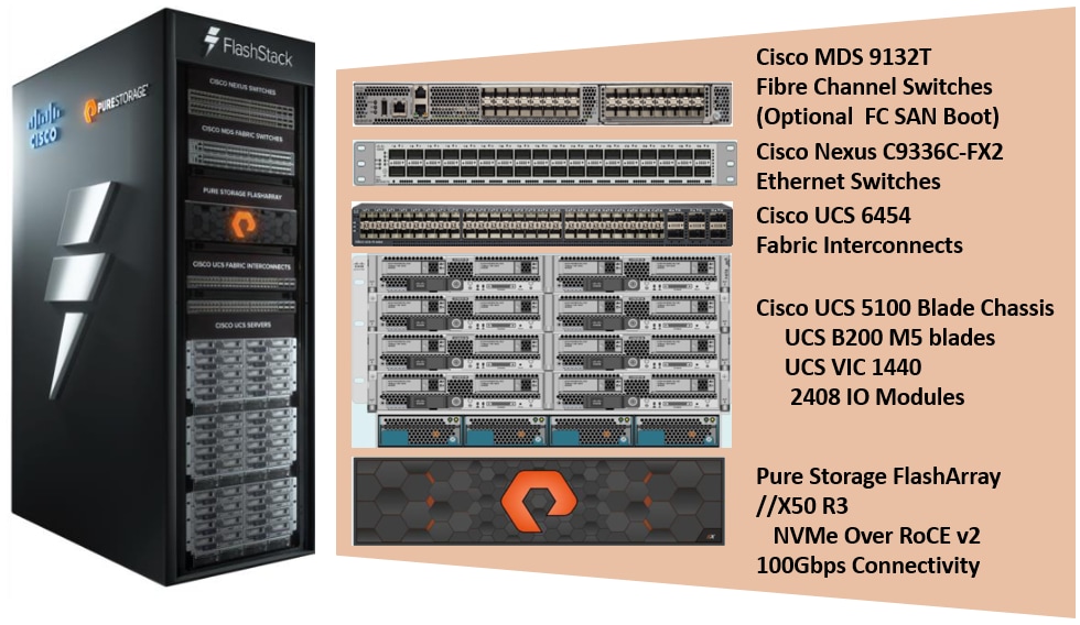
As shown in Figure 1, the reference architecture described in this document leverages the Pure Storage FlashArray//X50 R3 controllers for shared storage, Cisco UCS B200 M5 Blade Server for compute, and Cisco Nexus 9000 Series switches for storage connectivity using NVMe/RoCEv2.
Booting Cisco UCS B200 M5 blade servers from SAN offers true portability of Cisco UCS service profiles from failed node to a new node there by reducing downtime of applications running on the nodes. This solution is validated booting Cisco UCS B200 M5 nodes from Pure Storage using Fibre Channel protocol. Cisco Nexus MDS switches are used to provide required FC connectivity between hosts and Pure Storage.
Other alternative boot options such as SAN boot using iSCSI protocol OR local disk-based booting (this option limits service profile mobility) were not tried in this configuration.
![]() NVMe/RoCE v2 does not support booting from SAN as of this release.
NVMe/RoCE v2 does not support booting from SAN as of this release.
The components of FlashStack architecture are connected and configured according to best practices of both Cisco and Pure Storage and provides the ideal platform for running a variety of enterprise database workloads with confidence. FlashStack can scale up for greater performance and capacity (adding compute, network, or storage resources independently as needed), or it can scale out for environments that require multiple consistent deployments. The architecture brings together a simple, wire once solution that is SAN booted from FC and is highly resilient at each layer of the design.
Cisco and Pure Storage have also built a robust and experienced support team focused on FlashStack solutions, from customer account and technical sales representatives to professional services and technical support engineers. The support alliance between Pure Storage and Cisco gives customers and channel services partners direct access to technical experts who collaborate with cross vendors and have access to shared lab resources to resolve potential issues.
For more details and specifications of individual components, go to the References section where all the necessary links are provided.
FlashStack is a defined set of hardware and software that serves as an integrated foundation for both virtualized and non-virtualized solutions. The solution is built on Cisco Unified Computing System, Cisco Nexus, Pure storage FlashArray, and RedHat Enterprise Linux software in a single package. The design is flexible enough that the networking, computing, and storage can fit in one datacenter rack or be deployed according to a customer's data center design. Port density enables the networking components to accommodate multiple configurations of this kind.
Figure 2 shows the architecture diagram of the components and the network connections used for this solution.
Figure 2. FlashStack With Cisco UCS 6454 Fabric Interconnects and Pure Storage FlashArray
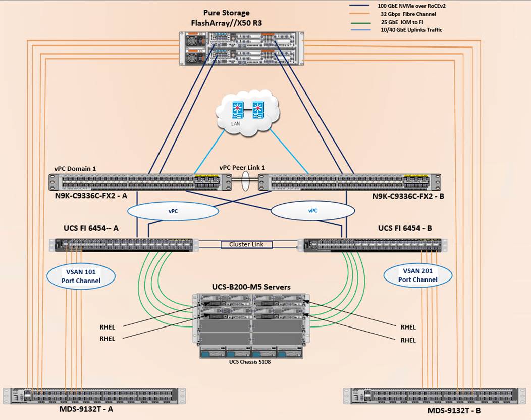
This design supports 100Gbps NVMe/RoCE connectivity between the Fabric Interconnect and Pure Storage FlashArray//X50 R3 via Cisco Nexus C9336C-FX2 Ethernet switches. A pair of Cisco Nexus 9000 series switches are configured in high availability mode using Virtual Port Channel (vPC). These switches are also configured with required Quality of Services (QoS) to enable lossless transmission of NVMe storage traffic. Cisco Nexus switches are also connected to the customer’s network for SQL Server connectivity and infrastructure management. Between Cisco UCS 5108 Blade Chassis and the Cisco UCS Fabric Interconnect, up to 8x 25Gbps uplink cables can be connected using 2408 IO module on each side of Fabric there by supporting up to 200Gbps network bandwidth on each side of the fabric. These 25Gbps cables will carry both storage and network traffic. On each Fabric Interconnect, first four ports (1 to 4) are configured as Fibre Channel (FC) ports and are connected to the Cisco MDS switches as shown in the above diagram. On each side of the fabric, these four ports form a Fibre Channel Port Channel with aggregated bandwidth of 128Gbps (4x 32Gbps). This reference architecture reinforces the "wire-once" strategy, because as additional storage is added to the architecture, no re-cabling is required from the hosts to the Cisco UCS fabric interconnect.
The following components were used to validate and test the solution:
● 1x Cisco 5108 chassis with Cisco UCS 2408 IO Modules
● 2x Cisco UCS B200 M5 Blade Servers with Cisco VIC 1440 for compute
● Pair of Cisco Nexus 9336C-FX2 switches for Storage connectivity using NVMe/RoCEv2
● Pair of Cisco UCS 6454 fabric interconnects for managing the system
● Pair of Cisco MDS 9132T for booting UCS B200 M5 from SAN using Fibre Channel protocol
● Pure Storage FlashArray//X50R3 with NVMe Disks
In this solution, RedHat Enterprise Linux (RHEL) bare metal environment is tested and validated for deploying SQL Server 2019 databases. The RHEL hosts are configured to boot from the Pure Storage FlashArray using Fibre Channel. SQL Server 2019 database files are stored over multiple NVMe devices which are accessed using NVMe protocol over 100Gbps connectivity.
Table 1 lists the hardware and software components along with image versions used in the solution.
Table 1. Hardware and Software Components Specifications
| Layer |
Device |
Image |
Components |
| Compute |
Cisco UCS 4th Generation 6454 Fabric Interconnects |
4.1(1c) UCS-6400-k9-bundle-Infra.4.1.1c.A UCS-6400-k9-bundle-c series.4.1.1c.C UCS-6400-k9-bundle-b-series.4.1.1c.B |
Includes Cisco 5108 blade chassis with Cisco UCS 2408 IO Modules Cisco UCS B200 M5 blades with Cisco UCS VIC 1440 adapter. Each blade is configured with 2x Intel Xeon 6248 Gold processors and 384 GB (12x 32G) Memory |
| Network Switches |
Includes Cisco Nexus 9336C-FX2 |
NX-OS: 9.3(3) |
|
| Fibre Channel Switches |
Cisco MDS 9132T |
8.4(1) |
|
| Storage Controllers |
Pure Storage Purity OS version |
FlashArray//X50 R3 Purity //FA 5.3.5 |
//X50 R3 is equipped with a pair of controllers and each controller has 1x 4-port 32 Gbps FC Adapter and 1x 2-port 100Gbps Adapter 20x 1.92TB NVMe drives with total RAW Capacity of 26.83TB with 20x 1.92TB |
| Operating System |
RedHat Enterprise Linux 7.6 |
Linux kernel 3.10.0-957.27.2.el7.x86_64 |
|
| VIC 1440 drivers |
Cisco VIC Ethernet NIC Driver (nenic) Cisco VIC Ethernet NIC rdma Driver (nenic_rdma) Cisco VIC Ethernet NIC Driver (nfnic) |
4.0.0.8-802.24.rhel7u6.x86_64
1.0.0.8-802.24.rhel7u6.x86_64 2.0.0.60-141.0.rhel7u6.x86_64 |
Cisco VIC 1440 Ethernet Driver for RHEL 7.6 Cisco VIC 1440 Ethernet rdma Driver for RHEL 7.6 Cisco VIC 1440 FC Driver for RHEL 7.6 |
|
|
Microsoft SQL Server |
2019 (15.0.4053.23) |
Relational Database Management |
![]() Release 4.1(1c) is deprecated and firmware files are no longer available. For more information, refer to: Field Notice: FN - 70595. Cisco recommends that you upgrade to release 4.1(1d) or later.
Release 4.1(1c) is deprecated and firmware files are no longer available. For more information, refer to: Field Notice: FN - 70595. Cisco recommends that you upgrade to release 4.1(1d) or later.
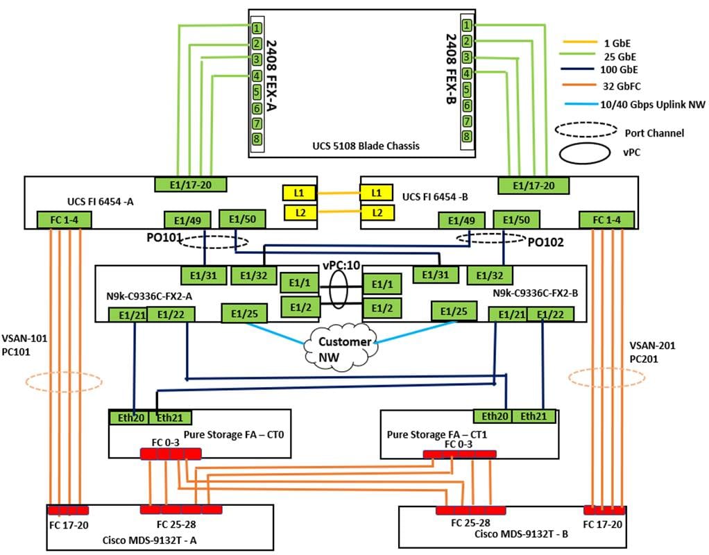
Physical Topology
Figure 3 details the cabling used for this validation. As shown, the Pure Storage FlashArray//X50 R3 array is connected to Cisco Nexus 9000 series switches and then to Cisco UCS Fabric Interconnects over multiple 100Gbps links. Cisco UCS 5108 blade chassis is connected to the Cisco UCS Fabric interconnects through IOM modules using 4x 25Gbps Ethernet connections on each side of the Fabric. The Cisco UCS Fabric Interconnects are also connected to Cisco MDS switches using multiple 32Gbps FC links for SAN boot using Fibre Channel protocol. Finally, the Cisco Nexus switches are connected to the customer network. Each Cisco UCS fabric interconnect and Cisco Nexus switch is connected to the out-of-band network switch, and each Pure Storage FlashArray controller has a connection to the out-of-band network switch.
The following tables detail the cabling connectivity used for this solution.
Table 2. Cisco Nexus 9336C-FX2-A Cabling information
| Local Device |
Local Port |
Connection |
Remote Device |
Remote Port |
| Cisco Nexus 9336C-FX2-A |
Eth 1/1 |
100Gbe |
Cisco Nexus 9336C-FX2-B |
Eth 1/1 |
| Eth 1/2 |
100Gbe |
Cisco Nexus 9336C-FX2-B |
Eth 1/2 |
|
| Eth 1/21 |
100Gbe |
Pure Storage FlashArray//X50 R3 Controller 0 |
CT0.ETH20 |
|
| Eth 1/22 |
100Gbe |
Pure Storage FlashArray//X50 R3 Controller 1 |
CT1.ETH20 |
|
| Eth 1/31 |
100Gbe |
UCS 6454-A |
Eth 1/49 |
|
| Eth 1/32 |
100Gbe |
UCS 6454-B |
Eth 1/49 |
|
| Eth 1/25 |
10/40/100 Gbe |
Upstream Network Switch |
Any |
|
| Mgmt0 |
Gbe |
Gbe Management |
Any |
Table 3. Cisco Nexus 9336C-FX2-B Cabling information
| Local Device |
Local Port |
Connection |
Remote Device |
Remote Port |
| Cisco Nexus 9336C-FX2-B |
Eth 1/1 |
100Gbe |
Cisco Nexus 9336C-FX2-A |
Eth 1/1 |
| Eth 1/2 |
100Gbe |
Cisco Nexus 9336C-FX2-A |
Eth 1/ 2 |
|
| Eth 1/21 |
100Gbe |
Pure Storage FlashArray//X50 R3 Controller 0 |
CT0.ETH21 |
|
| Eth 1/22 |
100Gbe |
Pure Storage FlashArray//X50 R3 Controller 1 |
CT1.ETH21 |
|
| Eth 1/31 |
100Gbe |
UCS 6454-A |
Eth 1/50 |
|
| Eth 1/32 |
100Gbe |
UCS 6454-B |
Eth 1/50 |
|
| Eth 1/25 |
10/40/100 Gbe |
Upstream Network Switch |
Any |
|
| Mgmt0 |
Gbe |
Gbe Management |
Any |
Table 4. Cisco UCS-6454-A Cabling information
| Local Device |
Local Port |
Connection |
Remote Device |
Remote Port |
| Cisco UCS 6454-A |
Eth 1/49 |
100Gbe |
Cisco Nexus 9336C-FX2-A |
Eth 1/31 |
| Eth 1/50 |
100Gbe |
Cisco Nexus 9336C-FX2-B |
Eth 1/31 |
|
| Eth 1/17 |
25Gbe |
Cisco UCS Chassis 1 2408 FEX A |
IOM 1/1 |
|
| Eth 1/18 |
25Gbe |
Cisco UCS Chassis 1 2408 FEX A |
IOM1/ 2 |
|
| Eth 1/19 |
25Gbe |
Cisco UCS Chassis 1 2408 FEX A |
IOM 1/3 |
|
| Eth 1/20 |
25Gbe |
Cisco UCS Chassis 1 2408 FEX A |
IOM 1/ 4 |
|
| FC 1/1 |
32G FC |
Cisco MDS 9132T-A |
FC1/17 |
|
| FC 1/ 2 |
32G FC |
Cisco MDS 9132T-A |
FC1/18 |
|
| FC 1/3 |
32G FC |
Cisco MDS 9132T-A |
FC1/19 |
|
| FC 1/ 4 |
32G FC |
Cisco MDS 9132T-A |
FC1/20 |
|
| L1/L2 |
Gbe |
UCS 6454-B |
L1/L2 |
|
| Mgmt0 |
Gbe |
Gbe Management |
Any |
Table 5. Cisco UCS-6454-B Cabling information
| Local Device |
Local Port |
Connection |
Remote Device |
Remote Port |
| Cisco UCS 6454-B |
Eth 1/49 |
100Gbe |
Cisco Nexus 9336C-FX2-A |
Eth 1/32 |
| Eth 1/50 |
100Gbe |
Cisco Nexus 9336C-FX2-B |
Eth 1/32 |
|
| Eth 1/17 |
25Gbe |
Cisco UCS Chassis 1 2408 FEX B |
IOM 1/1 |
|
| Eth 1/18 |
25Gbe |
Cisco UCS Chassis 1 2408 FEX B |
IOM1/ 2 |
|
| Eth 1/19 |
25Gbe |
Cisco UCS Chassis 1 2408 FEX B |
IOM 1/3 |
|
| Eth 1/20 |
25Gbe |
Cisco UCS Chassis 1 2408 FEX B |
IOM 1/ 4 |
|
| FC 1/1 |
32G FC |
Cisco MDS 9132T-B |
FC1/17 |
|
| FC 1/ 2 |
32G FC |
Cisco MDS 9132T-B |
FC1/18 |
|
| FC 1/3 |
32G FC |
Cisco MDS 9132T-B |
FC1/19 |
|
| FC 1/ 4 |
32G FC |
Cisco MDS 9132T-B |
FC1/20 |
|
| L1/L2 |
Gbe |
UCS 6454-A |
L1/L2 |
|
| Mgmt0 |
Gbe |
Gbe Management |
Any |
Table 6. Cisco MDS-9132T-A Cabling information
| Local Device |
Local Port |
Connection |
Remote Device |
Remote Port |
| Cisco MDS-9132T-A |
FC1/17 |
32G FC |
Cisco UCS 6454-A |
FC 1/1 |
| FC1/18 |
32G FC |
Cisco UCS 6454-A |
FC 1/ 2 |
|
| FC1/19 |
32G FC |
Cisco UCS 6454-A |
FC 1/3 |
|
| FC1/20 |
32G FC |
Cisco UCS 6454-A |
FC 1/ 4 |
|
| FC1/25 |
32G FC |
Pure Storage FlashArray//X50 R3 Controller 0 |
CT0.FC0 |
|
| FC1/26 |
32G FC |
Pure Storage FlashArray//X50 R3 Controller 0 |
CT0.FC1 |
|
| FC1/27 |
32G FC |
Pure Storage FlashArray//X50 R3 Controller 1 |
CT1.FC0 |
|
| FC1/28 |
32G FC |
Pure Storage FlashArray//X50 R3 Controller 1 |
CT1.FC1 |
|
| Mgmt0 |
Gbe |
Gbe Management |
Any |
Table 7. Cisco MDS-9132T-B Cabling information
| Local Device |
Local Port |
Connection |
Remote Device |
Remote Port |
| Cisco MDS-9132T-B |
FC1/17 |
32G FC |
Cisco UCS 6454-B |
FC 1/1 |
| FC1/18 |
32G FC |
Cisco UCS 6454-B |
FC 1/ 2 |
|
| FC1/19 |
32G FC |
Cisco UCS 6454-B |
FC 1/3 |
|
| FC1/20 |
32G FC |
Cisco UCS 6454-B |
FC 1/ 4 |
|
| FC1/25 |
32G FC |
Pure Storage FlashArray//X50 R3 Controller 0 |
CT0.FC2 |
|
| FC1/26 |
32G FC |
Pure Storage FlashArray//X50 R3 Controller 0 |
CT0.FC3 |
|
| FC1/27 |
32G FC |
Pure Storage FlashArray//X50 R3 Controller 1 |
CT1.FC2 |
|
| FC1/28 |
32G FC |
Pure Storage FlashArray//X50 R3 Controller 1 |
CT1.FC3 |
|
| Mgmt0 |
Gbe |
Gbe Management |
Any |
Table 8. Pure Storage FlashArray//50 R3 Controller 0 Cabling information
| Local Device |
Local Port |
Connection |
Remote Device |
Remote Port |
| FlashArray//X50 R3 Conrtroller-0 |
CT0.Eth20 |
100Gbe |
Cisco Nexus 9336C-FX2-A |
Eth1/21 |
| CT0.Eth21 |
100Gbe |
Cisco Nexus 9336C-FX2-B |
Eth1/21 |
|
| CT0.FC0 |
32G FC |
Cisco MDS 9132T-A |
FC 1/25 |
|
| CT0.FC1 |
32G FC |
Cisco MDS 9132T-A |
FC 1/26 |
|
| CT0.FC2 |
32G FC |
Cisco MDS 9132T-B |
FC 1/25 |
|
| CT0.FC3 |
32G FC |
Cisco MDS 9132T-B |
FC 1/26 |
|
| Mgmt0 |
Gbe |
Gbe Management |
Any |
Table 9. Pure Storage FlashArray//50 R3 Controller 1 Cabling information
| Local Device |
Local Port |
Connection |
Remote Device |
Remote Port |
| FlashArray//X50 R3 Conrtroller-1 |
CT1.Eth20 |
100Gbe |
Cisco Nexus 9336C-FX2-A |
Eth1/22 |
| CT1.Eth21 |
100Gbe |
Cisco Nexus 9336C-FX2-B |
Eth1/22 |
|
| CT1.FC0 |
32G FC |
Cisco MDS 9132T-A |
FC 1/27 |
|
| CT1.FC1 |
32G FC |
Cisco MDS 9132T-A |
FC 1/28 |
|
| CT1.FC2 |
32G FC |
Cisco MDS 9132T-B |
FC 1/27 |
|
| CT1.FC3 |
32G FC |
Cisco MDS 9132T-B |
FC 1/28 |
|
| Mgmt0 |
Gbe |
Gbe Management |
Any |
The following table lists the VLAN used for this solution.
Table 10. VLANS
| VLAN NAME |
VLAN ID |
Description |
| Default VLAN |
1 |
Native VLAN |
| IB-MGMT |
137 |
VLAN for Inband management traffic and SQL public traffic |
| Storage RoCE-A |
120 |
VLAN for RoCE Storage traffic |
| Storage RoCE-B |
130 |
VLAN for RoCE Storage traffic |
The following table lists the VSANs used for booting Cisco UCS B200 M5 blades from Pure Storage.
Table 11. VSANs used for SAN Boot
| VLAN NAME |
VLAN ID |
Description |
| FlashStack-VSAN-A |
101 |
VSAN ID for Fabric-A |
| FlashStack-VSAN-B |
201 |
VSAN ID for Fabric-B |
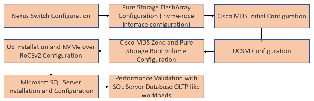
This section provides configuration steps for deploying a FlashStack solution featuring end-to-end NVMe connectivity between compute and storage using RoCEv2 protocol. Figure 4 shows the deployment steps followed for this solution.
Figure 4. Flow of Deployment and Solution Performance Validation Steps
Cisco Nexus Switch Configuration
This section details the high-level steps to configure Cisco Nexus Switches.
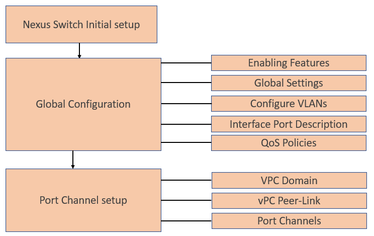
Figure 5. Nexus Switch Configuration Flow
Cisco Nexus Switch Initial Setup
This section provides detailed instructions for the configuration of the Cisco Nexus 9336C-FX2 switches used in this FlashStack solution. Some changes may be appropriate for a customer’s environment, but care should be taken when stepping outside of these instructions as it may lead to an improper configuration.
Cisco Nexus Switch A
Abort Power on Auto Provisioning and continue with normal setup? (yes/no) [n]: yes
Do you want to enforce secure password standard (yes/no) [y]: Enter
Enter the password for "admin": <password>
Confirm the password for "admin": <password>
Would you like to enter the basic configuration dialog (yes/no): yes
Create another login account (yes/no) [n]: Enter
Configure read-only SNMP community string (yes/no) [n]: Enter
Configure read-write SNMP community string (yes/no) [n]: Enter
Enter the switch name: <nexus-A-hostname>
Continue with Out-of-band (mgmt0) management configuration? (yes/no) [y]: Enter
Mgmt0 IPv4 address: <nexus-A-mgmt0-ip>
Mgmt0 IPv4 netmask: <nexus-A-mgmt0-netmask>
Configure the default gateway? (yes/no) [y]: Enter
IPv4 address of the default gateway: <nexus-A-mgmt0-gw>
Configure advanced IP options? (yes/no) [n]: Enter
Enable the telnet service? (yes/no) [n]: Enter
Enable the ssh service? (yes/no) [y]: Enter
Type of ssh key you would like to generate (dsa/rsa) [rsa]: Enter
Number of rsa key bits <1024-2048> [1024]: Enter
Configure the ntp server? (yes/no) [n]: y
NTP server IPv4 address: <global-ntp-server-ip>
Configure default interface layer (L3/L2) [L3]: L2
Configure default switchport interface state (shut/noshut) [noshut]: Enter
Configure CoPP system profile (strict/moderate/lenient/dense/skip) [strict]: Enter
Would you like to edit the configuration? (yes/no) [n]: Enter
Cisco Nexus Switch B
Follow the same steps from Nexus Switch A to setup the initial configuration for the Cisco Nexus B and make sure to change the relevant switch host name and management address.
Global Configuration
The following global configuration to be configured on both the Switches. Login as admin user into Cisco Nexus Switch-A and run the following commands serially. Change the gateway IP and VLAN IDs, Port Channel IDs and so on, as specific to your deployment.
configure terminal
feature interface-vlan
feature hsrp
feature lacp
feature vpc
feature lldp
feature udld
spanning-tree port type edge bpduguard default
spanning-tree port type network default
port-channel load-balance src-dst l4port
vrf context management
ip route 0.0.0.0/0 10.29.137.1
policy-map type network-qos jumbo
class type network-qos class-default
mtu 9216
policy-map type network-qos RoCE-UCS-NQ-Policy
class type network-qos c-8q-nq3
pause pfc-cos 3
mtu 9216
class type network-qos c-8q-nq5
pause pfc-cos 5
mtu 9216
class-map type qos match-all class-pure
match dscp 46
class-map type qos match-all class-platinum
match cos 5
class-map type qos match-all class-best-effort
match cos 0
policy-map type qos policy-pure
description qos policy for pure ports
class class-pure
set qos-group 5
set cos 5
set dscp 46
policy-map type qos system_qos_policy
description qos policy for FI to Nexus ports
class class-platinum
set qos-group 5
set dscp 46
set cos 5
class class-best-effort
set qos-group 0
system qos
service-policy type network-qos RoCE-UCS-NQ-Policy
copy running-config startup-config
Log into the Cisco Nexus Switch B as admin user and repeat the above steps to configure the Global settings.
Configure VLANs
Log into Cisco Nexus Switch A as admin users and run the following commands to create necessary Virtual Local Area Networks (VLANs).
configure terminal
vlan 137
name SQL_Mgmt_Network
no shutdown
vlan 120
name RoCE_A
no shutdown
vlan 130
name RoCE_B
no shutdown
copy running-config startup-config
Log into Cisco Nexus Switch B as admin users and run the above commands to create necessary Virtual Local Area Networks (VLANs).
Interface Port Descriptions
To add individual port descriptions for troubleshooting activity and verification for switch A, enter the following commands from the global configuration mode:
configure terminal
interface Ethernet1/1
description Nexus-B-Eth1/1 Peer Link
interface Ethernet1/2
description Nexus-B-Eth1/2 Peer Link
interface Ethernet1/21
description Pure-CT0-ETH20
interface Ethernet1/22
description Pure-CT1-ETH20
interface Ethernet1/31
description UCS-6454-FI-A-49
interface Ethernet1/32
description UCS-6454-FI-B-49
interface Ethernet1/25
description Network-Uplink-A
copy running-config startup-config
To add individual port descriptions for troubleshooting activity and verification for switch B, enter the following commands from the global configuration mode:
configure terminal
interface Ethernet1/1
description Nexus-A-Eth1/1 Peer Link
interface Ethernet1/2
description Nexus-A-Eth1/2 Peer Link
interface Ethernet1/21
description Pure-CT0-ETH21
interface Ethernet1/22
description Pure-CT1-ETH21
interface Ethernet1/31
description UCS-6454-FI-A-50
interface Ethernet1/32
description UCS-6454-FI-B-50
interface Ethernet1/25
description Network-Uplink-B
copy running-config startup-config
![]() Add the required uplink network configuration on the Cisco Nexus switches as appropriate. For this solution, one uplink is used for the customer Network connectivity from the Cisco Nexus switches.
Add the required uplink network configuration on the Cisco Nexus switches as appropriate. For this solution, one uplink is used for the customer Network connectivity from the Cisco Nexus switches.
Virtual Port Channel (vPC) Configuration
In Cisco Nexus Switch topology, a single vPC feature is enabled to provide high availability, faster convergence in the event of a failure, and greater throughput. A vPC domain will be assigned a unique number from 1-1000 and will handle the vPC settings specified within the switches. To set the vPC domain configuration on Cisco Nexus Switch-A, run the following commands.
configure terminal
vpc domain 10
peer-switch
role priority 10
peer-keepalive destination 10.29.137.7 source 10.29.137.6 vrf management
delay restore 150
peer-gateway
auto-recovery
ip arp synchronize
interface port-channel 10
description vPC peer-link
switchport mode trunk
switchport trunk allowed vlan 137,120,130
spanning-tree port type network
service-policy type qos input system_qos_policy
vpc peer-link
no shutdown
copy running-config startup-config
To set the vPC domain configuration on Cisco Nexus-B, run the following commands:
configure terminal
vpc domain 10
peer-switch
role priority 20
peer-keepalive destination 10.29.137.6 source 10.29.137.7 vrf management
delay restore 150
peer-gateway
auto-recovery
ip arp synchronize
interface port-channel 10
description vPC peer-link
switchport mode trunk
switchport trunk allowed vlan 137,120,130
spanning-tree port type network
service-policy type qos input system_qos_policy
vpc peer-link
no shutdown
copy running-config startup-config
vPC Peer-Link Configuration
On each switch, configure the Port Channel member interfaces that will be part of the vPC Peer Link and configure the vPC Peer Link. Run the following commands on both Cisco Nexus switches.
configure terminal
interface ethernet 1/1-2
switchport mode trunk
switchport trunk allowed vlan 137,120,130
channel-group 10 mode active
no shutdown
copy running-config startup-config
Configure Port Channels
On each switch, configure the Port Channel member interfaces and the vPC Port Channels to the Cisco UCS Fabric Interconnect and the upstream network switches.
Cisco Nexus Connection vPC to UCS Fabric Interconnect A. Run the following commands on both Cisco Nexus Switches (A and B):
configure terminal
int port-channel 101
description vPC-FI-A
switchport mode trunk
switchport trunk allowed vlan 137,120,130
spanning-tree port type edge trunk
mtu 9216
service-policy type qos input system_qos_policy
vpc 101
no shutdown
interface ethernet 1/31
switchport mode trunk
switchport trunk allowed vlan 137,120,130
spanning-tree port type edge trunk
mtu 9216
channel-group 101 mode active
no shutdown
Cisco Nexus Connection vPC to Cisco UCS Fabric Interconnect B. Run the following commands on both Cisco Nexus Switches (A and B):
configure terminal
interface port-channel 102
description vPC-FI-B
switchport mode trunk
switchport trunk allowed vlan 137,120,130
spanning-tree port type edge trunk
mtu 9216
service-policy type qos input system_qos_policy
vpc 102
no shutdown
interface ethernet 1/32
switchport mode trunk
switchport trunk allowed vlan 137,120,130
spanning-tree port type edge trunk
mtu 9216
channel-group 102 mode active
no shutdown
copy running-config startup-config
Cisco Nexus connection to Upstream Network Switches. Run the following commands on both Cisco Nexus Switches (A and B):
interface ethernet 1/25
switchport mode trunk
switchport trunk allowed vlan 137,120,130
no shutdown
copy running-config startup-config
Verify All Port Channels and vPC Domains
To verify all vPC statuses, follow this step:
1. Log into the Cisco Nexus switches as admin users and run the following commands to verify all the vPC and port channel statuses as shown below.
Figure 6. Port Channel Summary
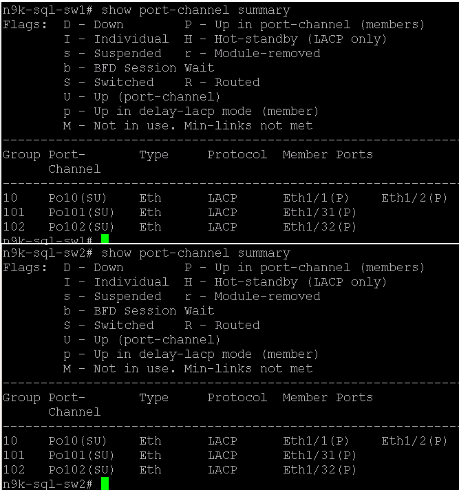
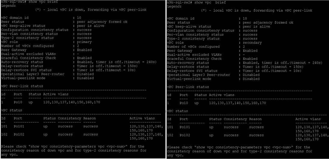
Figure 7. VPC Status
Configure Storage Ports on Cisco Nexus Switches
This section details the steps to configure the Pure storage ports on Cisco Nexus switches. Table 12 lists the port connectivity between the Cisco Nexus Switches and Pure Storage FlashArray//X50 R3.
| Nexus Ports |
Pure Storage Ports |
VLANs Allowed |
IP Configured on Pure Storage Interfaces |
| N9k-A Port 1/21 |
Storage Controller CT0.Eth 20 |
120 |
200.200.120.3 |
| N9k-A Port 1/22 |
Storage Controller CT1.Eth 20 |
130 |
200.200.130.4 |
| N9k-B Port 1/21 |
Storage Controller CT0.Eth 21 |
130 |
200.200.130.3 |
| N9k-B Port 1/22 |
Storage Controller CT1.Eth 21 |
120 |
200.200.120.4 |
To configure Pure Storage ports on the Cisco Nexus Switches, follow these steps:
1. Log into the Nexus Switch-A as admin user and run the following commands.
configure terminal
interface Ethernet1/21
switchport access vlan 120
priority-flow-control mode on
spanning-tree port type edge
mtu 9216
service-policy type qos input policy-pure
no shutdown
interface Ethernet1/22
switchport access vlan 130
priority-flow-control mode on
spanning-tree port type edge
mtu 9216
service-policy type qos input policy-pure
no shutdown
copy running-config startup-config
2. Log into the Nexus Switch-B as admin user and run the following commands.
configure terminal
interface Ethernet1/21
switchport access vlan 130
priority-flow-control mode on
spanning-tree port type edge
mtu 9216
service-policy type qos input policy-pure
no shutdown
interface Ethernet1/22
switchport access vlan 120
priority-flow-control mode on
spanning-tree port type edge
mtu 9216
service-policy type qos input policy-pure
no shutdown
copy running-config startup-config
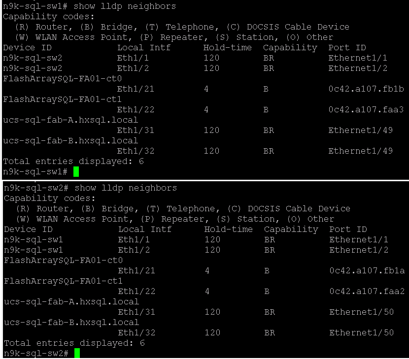
3. Verify the connectivity on all the Nexus switches as shown below.
Figure 8. Verifying Connectivity
Pure Storage FlashArray//X50 R3 Configuration
This section describes the high-level steps to configure Pure Storage FlashArray//X50 R3 network interfaces required for NVMe storage connectivity over RoCE. For this solution, Pure Storage FlashArray was loaded with Purity//FA Version 5.3.5, which supports NVMe/RoCE.
The hosts were redundantly connected to the storage controllers through 4 x 100Gb connections (2 x 100Gb per storage controller module) from the redundant Cisco Nexus switches.
The FlashArray network settings were configured with three subnets across three VLANs. Storage Interfaces CT0.Eth0 and CT1.Eth0 were configured to access management for the storage on VLAN 137. Storage Interfaces (CT0.Eth20, CT0.Eth21, CT1.Eth20, and CT1.Eth21) were configured to run RoCE Storage network traffic on the VLAN 120 and VLAN 130 to access database storage from all the RedHat hosts running on Cisco UCS B200 M5 blade servers.
To configure network settings in Pure Storage FlashArray, follow these steps:
1. Open a web browser and connect to Pure Storage FlashArray//X50 R3 array using its virtual IP.
2. Enter username and password to open Pure storage Dashboard.
3. On the Pure storage Dashboard, go to settings -> Network.
4. Select the nvme-roce cable Interface and click on edit and provide IP Address, Netmask, Gateway and MTU as shown below.
Figure 9. Configuring nvme-roce Capable Network Interface on Pure Storage
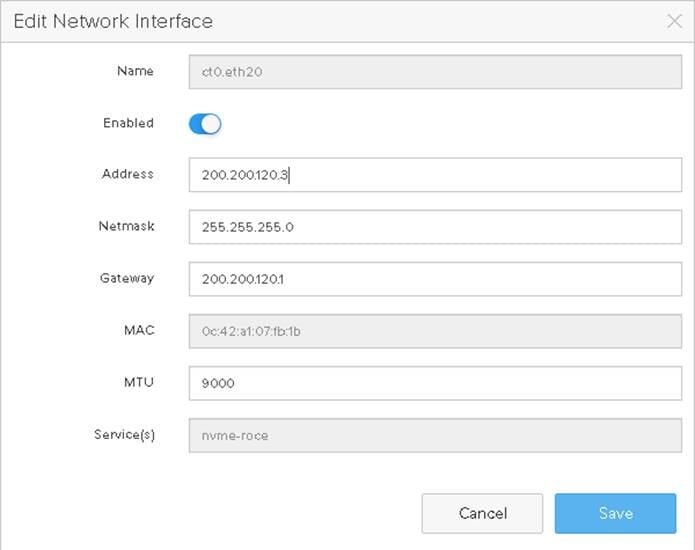
5. Repeat steps 1-4 to configure the remaining interfaces using information provided in Table 13.
Table 13. Pure Storage FlashArray nvme-roce Capable Interface Configuration
| Pure Storage Ports |
IP Address / Gateway |
MTU |
| Storage Controller CT0.Eth 20 |
200.200.120.3 / 200.200.120.1 |
9000 |
| Storage Controller CT0.Eth 21 |
200.200.130.3 / 200.200.130.1 |
9000 |
| Storage Controller CT1.Eth 20 |
200.200.130.4 / 200.200.130.1 |
9000 |
| Storage Controller CT1.Eth 21 |
200.200.120.4 / 200.200.120.1 |
9000 |
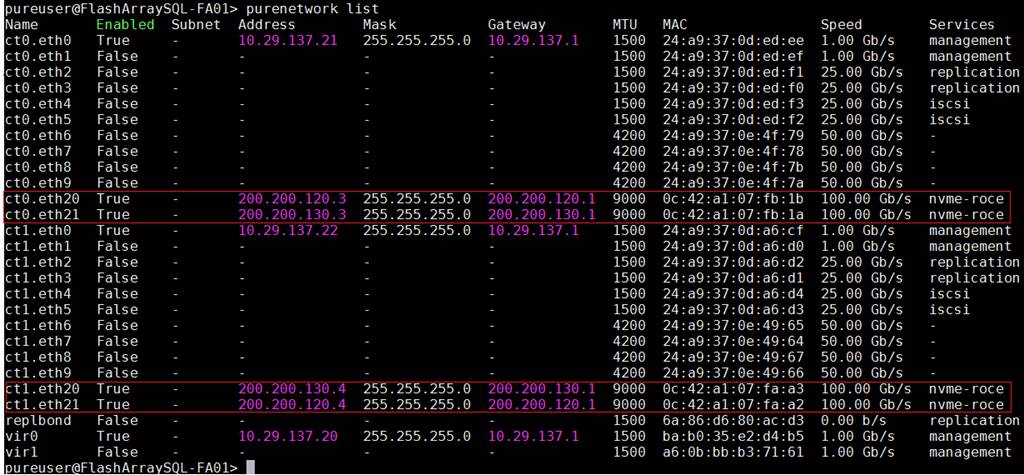
The final configuration can also be viewed and verified using Pure Storage CLI console (SSH into Pure Storage cluster virtual IP Address and connect with its credentials) as shown in Figure 10.
Figure 10. Verifying Pure Storage Network Interface Configuration using CLI
This section provides the steps to configure MDS switches to enable SAN boot for Cisco UCS B200 M5 blade servers using the Fibre Channel protocol.
The Initial setup of Cisco MDS Fibre Channel switches is standard and can be referenced here: https://www.cisco.com/en/US/docs/storage/san_switches/mds9000/sw/rel_3_x/configuration/guides/fm_3_3_1/gs.html
After the initial setup and once both fabric switches are up and running, run the following commands on both switches in the global configuration to enable features and settings. Change the NTP IP and VSAN IDs, port channel IDs, and so on, as specific to your deployment.
configure terminal
feature npiv
feature fport-channel-trunk
feature telnet
ntp server 72.163.32.44
Configure Port Channels, FC Interfaces, and VSAN on MDS Switches
On MDS 9132T A Switch create the VSAN that will be used for connectivity to the Cisco UCS Fabric Interconnect and the Pure Storage FlashArray. Assign this VSAN to the interfaces that will connect to the Pure Storage FlashArray, as well as the interfaces and the Port Channel they create that are connected to the Cisco UCS Fabric Interconnect.
To create a port channel and VSAN on the MDS Switch-A, run the following commands:
configure terminal
interface port-channel 101
switchport rate-mode dedicated
channel mode active
switchport speed auto
no shutdown
To create a port channel and VSAN on the MDS Switch-B, run the following commands:
configure terminal
interface port-channel 201
switchport rate-mode dedicated
channel mode active
switchport speed auto
no shutdown
On MDS Switch-A, the fc interfaces from 17 to 20 are used for connecting unified ports of UCS 6454 Fabric Interconnect-A. To configure the port names on MDS Switch-A switch, run the following commands:
configure terminal
interface fc 1/17
switchport speed auto
switchport description UCS6454-A-1
channel-group 101 force
no shutdown
interface fc 1/18
switchport speed auto
switchport description UCS6454-A-2
channel-group 101 force
no shutdown
interface fc 1/19
switchport speed auto
switchport description UCS6454-A-3
channel-group 101 force
no shutdown
interface fc 1/20
switchport speed auto
switchport description UCS6454-A-4
channel-group 101 force
no shutdown
On MDS Switch-A, the fc interfaces from 25 to 28 are used for connecting Pure Storage Controller ports. To configure the port names on MDS Switch-A switch, run the following commands:
configure terminal
interface fc1/25
switchport speed auto
switchport description Pure.CT0.FC0
switchport trunk mode off
port-license acquire
no shutdown
interface fc1/26
switchport speed auto
switchport description Pure.CT0.FC1
switchport trunk mode off
port-license acquire
no shutdown
interface fc1/27
switchport speed auto
switchport description Pure.CT1.FC0
switchport trunk mode off
port-license acquire
no shutdown
interface fc1/28
switchport speed auto
switchport description Pure.CT1.FC1
switchport trunk mode off
port-license acquire
no shutdown
On MDS Switch-B, the fc interfaces from 17 to 20 are used for connecting unified ports of Cisco UCS 6454 Fabric Interconnect-B. To configure the port names on MDS Switch-B switch, run the following commands:
configure terminal
interface fc 1/17
switchport speed auto
switchport description UCS6454-B-1
channel-group 201 force
no shutdown
interface fc 1/18
switchport speed auto
switchport description UCS6454-B-2
channel-group 201 force
no shutdown
interface fc 1/19
switchport speed auto
switchport description UCS6454-B-3
channel-group 201 force
no shutdown
interface fc 1/20
switchport speed auto
switchport description UCS6454-B-4
channel-group 201 force
no shutdown
On MDS Switch-B, the fc interfaces from 25 to 28 are used for connecting Pure Storage Controller ports. To configure the port names on MDS Switch-B switch, run the following commands:
configure terminal
interface fc1/25
switchport speed auto
switchport description Pure.CT0.FC2
switchport trunk mode off
port-license acquire
no shutdown
interface fc1/26
switchport speed auto
switchport description Pure.CT0.FC3
switchport trunk mode off
port-license acquire
no shutdown
interface fc1/27
switchport speed auto
switchport description Pure.CT1.FC2
switchport trunk mode off
port-license acquire
no shutdown
interface fc1/28
switchport speed auto
switchport description Pure.CT1.FC3
switchport trunk mode off
port-license acquire
no shutdown
On MDS Switch-A, Creating VSAN 101 and then adding the fc interfaces that connected to Pure storage controllers and fc interfaces (port channel 101) that are connected to UCS Fabric-A:
configure terminal
vsan database
vsan 101
vsan 101 name FS-FABRIC-A
exit
zone smart-zoning enable vsan 101
vsan database
vsan 101 interface fc 1/25-28
vsan 101 interface port-channel 101
exit
On MDS Switch-B, Creating VSAN 201 and then adding the fc interfaces that connected to Pure storage controllers and fc interfaces (port channel 201) that are connected to UCS Fabric-B:
configure terminal
vsan database
vsan 201
vsan 201 name FS-FABRIC-B
exit
zone smart-zoning enable vsan 201
vsan database
vsan 201 interface fc 1/25-28
vsan 201 interface port-channel 201
exit
The remaining configurations, such as device alias and zoning, need to be done after the UCSM is configured for Fibre Channel connectivity for SAN boot.
Cisco UCS Manager Configuration
This section discusses Cisco UCS Manager (Cisco UCSM) policies, profiles, templates, and service profiles specific to this FlashStack solution featuring NVMe/RoCE storage connectivity.
For the initial Cisco UCS Cluster setup, Cisco UCS call home, Cisco UCS Reporting, and upgrading Cisco UCSM to version 4.1, refer to the following links:
The following sections provide more details about specific configuration steps required for this solution.
NTP configuration for Time Synchronization
To synchronize the Cisco UCS Manager environment to the NTP server, follow these steps:
1. In Cisco UCS Manager, in the navigation pane, click the Admin tab.
2. Select All > Time zone Management.
3. In the Properties pane, select the appropriate time zone in the Time zone menu.
4. Click Save Changes and then click OK.
5. Click Add NTP Server.
6. Enter the NTP server IP address and click OK.
7. Click OK to finish.
Chassis Discovery policy
Setting the discovery policy simplifies the addition of the Cisco UCS B-Series chassis.
To modify the chassis discovery policy, follow these steps:
1. In Cisco UCS Manager, click the Equipment tab in the navigation pane and select Policies from the drop-down list.
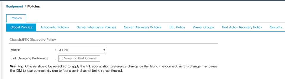
2. Under Global Policies, set the Chassis/FEX Discovery Policy to match the number of uplink ports that are cabled between the chassis or fabric extenders (FEXes) and the fabric interconnects. For this testing and validation, the value “4 Link” is used as there are four uplinks connected from each of Fabric as shown in the figure below.
3. Set the Link Grouping Preference to Port Channel.
4. Leave other settings alone or change if appropriate to your environment.
5. Click Save Changes.
6. Click OK.
Figure 11. Chassis Discovery Policy
Configure Server Ports
To enable server and uplink ports, follow these steps:
1. In Cisco UCS Manager, click the Equipment tab in the navigation pane.
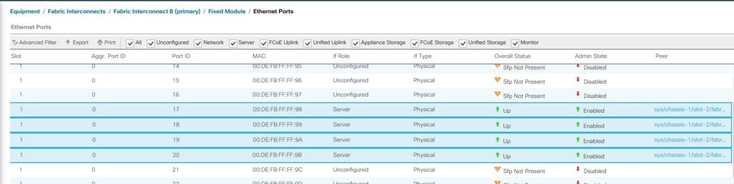
2. Select Equipment > Fabric Interconnects A > Flexible Module. Expand Ethernet Ports
3. Select the ports (for this solution ports are 17 to 20) which are connected to the chassis, right-click them, and select “Configure as Server Port.” Click Yes to confirm server ports and click OK.
4. Verify that the ports connected to the chassis are now configured as server ports.
5. Repeat steps 1 - 4 to configure the Server ports on the Fabric B. The following figure shows the server ports for Fabric B.
Figure 12. Server Port Configuration
6. After configuring Server Ports, acknowledge the Chassis. Go to Equipment > Chassis > Chassis 1 > General > Actions > select Acknowledge Chassis.
7. After acknowledging both the chassis, Re-acknowledge all the servers placed in the chassis. Go to Equipment > Chassis 1 > Servers > Server 1 > General > Actions > select Server Maintenance > select option Re-acknowledge and click OK. Similarly, repeat the process to acknowledge all the Servers installed in the Chassis.
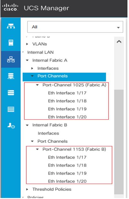
8. Once the acknowledgement of the Servers completed, verify the Port-Channel of Internal LAN. Go to tab LAN > Internal LAN > Internal Fabric A > Port Channels as shown below.
Figure 13. Internal Port-Channel for Server Ports
Configure Network Ports and Port-Channels to Upstream Cisco Nexus Switches
To configure the Network Ports and Port-Channels to the upstream Cisco Nexus Switches, follow these steps:
1. In Cisco UCS Manager, in the navigation pane, click the Equipment tab.
2. Select Equipment > Fabric Interconnects > Fabric Interconnect A > Fixed Module. Expand Ethernet Ports.
3. Select ports (for this solution ports are 49 & 50) that are connected to the Nexus switches, right-click them, and select Configure as Network Port.
4. Click Yes to confirm ports and click OK.
5. Verify the Ports connected to Nexus upstream switches are now configured as network ports.
6. Repeat steps 1-5 for Fabric Interconnect B for configuring Network ports. The figure below shows the network uplink ports for Fabric B.
Figure 14. Network Port Configuration
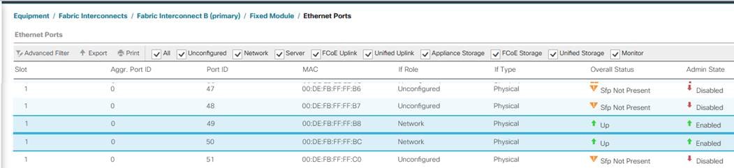
Now you have created four uplink ports on each Fabric Interconnect as shown above. These ports will be used to create Virtual Port Channel in the next section.
In this procedure, two port channels were created: one from Fabric A to both Cisco Nexus switches and one from Fabric B to both Cisco Nexus switches. To configure the necessary port channels in the Cisco UCS environment, follow these steps:
1. In Cisco UCS Manager, click the LAN tab in the navigation pane
2. Under LAN > LAN Cloud, expand node Fabric A tree:
a. Right-click Port Channels.
b. Select Create Port Channel.
c. Enter 101 as the unique ID of the port channel.
d. Enter VPC-Nexus-31 as the name of the port channel
e. Click Next.
f. Select Ethernet ports 49 and 50 for the port channel.
g. Click >> to add the ports to the port channel.
3. Click Finish to create the port channel and then click OK.
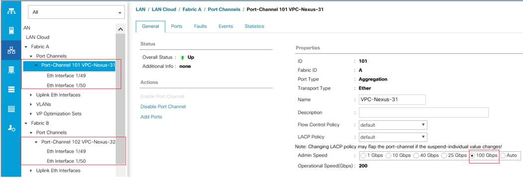
4. Ensure Admin speed on the port-channel is set to 100Gbps and Operational speed is calculated as 200Gbps.
5. Repeat steps 1-3 for Fabric Interconnect B, substituting 102 for the port channel number and VPC-Nexus-32 for the name. The resulting configuration should look like the screenshot shown below.
Figure 15. Port-Channel Configuration
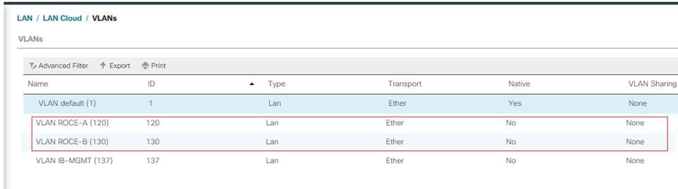
Configure VLANs
In this solution, four VLANs were created: one for public network (VLAN 137) traffic, and two storage network (VLAN 120 and VLAN 130) traffic. These four VLANs will be used in the vNIC templates that are discussed later.
To configure the necessary virtual local area networks (VLANs) for the Cisco UCS environment, follow these steps:
1. Click LAN > LAN Cloud.
2. Right-click VLANs.
3. Click Create VLANs.
4. Enter IB-MGMT as the name of the VLAN to be used for Public Network Traffic.
5. Keep the Common/Global option selected for the scope of the VLAN.
6. Enter 137 as the ID of the VLAN ID.
7. Keep the Sharing Type as None.
8. Click OK and then click OK again.
9. Repeat steps 1-8 to create the remaining VLANs (120 and 130) for Storage Connectivity using RoCE.
Figure 16. Port-Channel Configuration
Configure IP, UUDI, Server, MAC,WWN, WWPN Pools and Sub Organization
IP Pool Creation
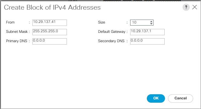
An IP address pool on the out of band management network must be created to facilitate KVM access to each compute node in the UCS domain. To create a block of IP addresses for server KVM access in the Cisco UCS environment, follow these steps:
1. In Cisco UCS Manager, in the navigation pane, click the LAN tab.
2. Click Pools > root > IP Pools >IP Pool ext-mgmt > right-click and select Create Block IP Addresses.
3. Click OK to complete the IP pool creation.
Figure 17. IP Pool Creation
UUID Suffix Pool
To configure the necessary universally unique identifier (UUID) suffix pool for the Cisco UCS environment, follow these steps:
1. Click Pools > root.
2. Right-click UUID Suffix Pools and then select Create UUID Suffix Pool.
3. Enter UUID-Pool as the name of the UUID name.
4. Optional: Enter a description for the UUID pool.
5. Keep the prefix at the derived option and select Sequential in as Assignment Order then click Next.
6. Click Add to add a block of UUIDs.
7. Create a starting point UUID as per your environment.
8. Specify a size for the UUID block that is sufficient to support the available blade or server resources.
Sub Organization (Optional)
It is important to keep all your project/department specific polices and pools in the dedicated organization. To configure the sub organization for this solution, follow the below steps:
1. Click Servers > Service Profiles > root > right-click Create Organization.
2. Enter a name ( For this solution “FlashStack-SQL” ) for organization and provide optional description.
3. Click Ok to complete Organization creation.
![]() In this FlashStack solution, unless specified the policies, pools, templates, service profiles and so on, will be created in the default root organization for this solution.
In this FlashStack solution, unless specified the policies, pools, templates, service profiles and so on, will be created in the default root organization for this solution.
Server Pool
To configure the necessary server pool for the Cisco UCS environment, follow these steps:
1. In Cisco UCS Manager, click the Servers tab in the navigation pane.
2. Click Pools > root > Sub-Organizations > FlashStack-SQL > right-click Server Pools > Select Create Server Pool.
3. Enter Infra-Pool as the name of the server pool.
4. Optional: Enter a description for the server pool then click Next.
5. Select all the servers and click > to add them to the server pool.
6. Click Finish and click OK.
Mac Pools
To configure the necessary server pool for the Cisco UCS environment, follow these steps:
1. In Cisco UCS Manager, click the LAN tab in the navigation pane.
2. Click Pools > root > right-click MAC Pools under the root organization.
3. Click Create MAC Pool to create the MAC address pool.
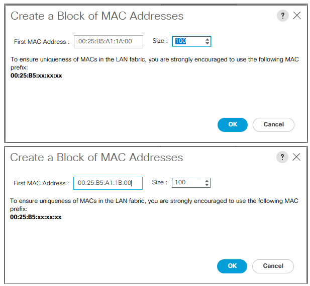
4. Enter MAC-Pool-A as the name for MAC pool.
5. Enter the seed MAC address and provide the number of MAC addresses to be provisioned.
6. Click OK and then click Finish.
7. In the confirmation message, click OK.
8. Create another pool with name MAC-Pool-B and provide the number of MAC addresses to be provisioned.
![]() For Cisco UCS deployments, the recommendation is to place 0A in the next-to-last octet of the starting MAC address to identify all of the MAC addresses as fabric A addresses. Similarly, place 0B for fabric B MAC pools. In this example, we have carried forward the of also embedding the extra building, floor and Cisco UCS domain number information giving us 00:25:B5:91:1A:00 and 00:25:B5:91:1B:00 as our first MAC addresses.
For Cisco UCS deployments, the recommendation is to place 0A in the next-to-last octet of the starting MAC address to identify all of the MAC addresses as fabric A addresses. Similarly, place 0B for fabric B MAC pools. In this example, we have carried forward the of also embedding the extra building, floor and Cisco UCS domain number information giving us 00:25:B5:91:1A:00 and 00:25:B5:91:1B:00 as our first MAC addresses.
The following figure shows the MAC-Pools blocks for fabric A and B.
Figure 18. MAC Pools
Defining WWN and WWPN Pools
To configure the necessary WWNN pool for the Cisco UCS environment, follow these steps on Cisco UCS Manager:
1. Click the SAN tab and then select Pools > root.
2. Right-click WWNN Pools under the root organization.
3. Click Create WWNN Pool to create the WWNN pool.
4. Enter WWNN_Pool_A for the name of the WWNN pool.
5. Optional: Enter a description for the WWNN pool.
6. Select Sequential for Assignment Order and click Next.
7. Click Add to add the Block of WWNN pool.
8. Modify the from filed as necessary for the UCS environment.
Figure 19. WWNN pool for FC Connectivity
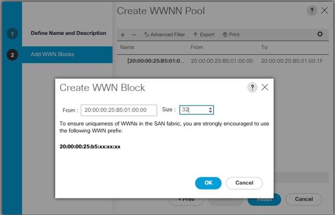
9. Specify a size of the WWNN block sufficient to support the available server resources. Click OK.
10. Click Finish to add the WWNN Pool. Click Ok again to complete the task.
![]() Modifications of the WWN block, as well as the WWPN and MAC Addresses, can convey identifying information for the Cisco UCS domain. Within the From field in our example, the 6th octet was changed from 00 to 01 to represent as identifying information for this being our first Cisco UCS domain.
Modifications of the WWN block, as well as the WWPN and MAC Addresses, can convey identifying information for the Cisco UCS domain. Within the From field in our example, the 6th octet was changed from 00 to 01 to represent as identifying information for this being our first Cisco UCS domain.
![]() Also, when having multiple Cisco UCS domains sitting in adjacency, it is important that these blocks, the WWNN, WWPN, and MAC hold differing values between each set.
Also, when having multiple Cisco UCS domains sitting in adjacency, it is important that these blocks, the WWNN, WWPN, and MAC hold differing values between each set.
To configure the necessary WWPN pools for the Cisco UCS environment, follow these steps:
1. In Cisco UCS Manager, click the SAN tab in the navigation pane.
2. Click Pools > root.
3. In this procedure, two WWPN pools are created, one for each switching fabric.
4. Right-click WWPN Pools under the root organization.
5. Click Create WWPN Pool to create the WWPN pool.
6. Enter WWPN_Pool_A as the name of the WWPN pool. Optionally enter a description for the WWPN pool.
7. Select Sequential for Assignment Order. Click Next and Click Add to add block of WWN names.
8. Specify a starting WWPN.
Figure 20. WWPN pool for FC Connectivity
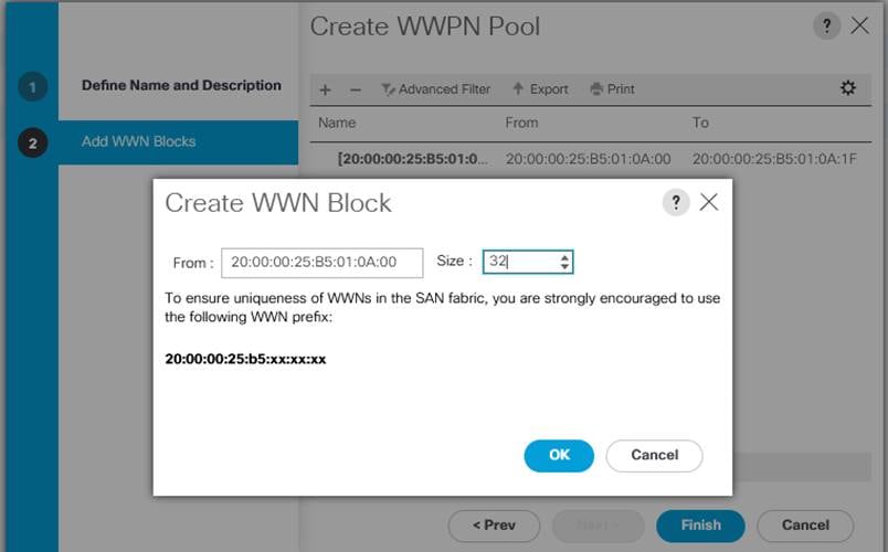
![]() For the FlashStack solution, the recommendation is to place 0A in the next-to-last octet of the starting WWPN to identify all of the WWPNs as fabric A addresses. Merging this with the pattern we used for the WWNN we see a WWPN block starting with 20:00:00:25:B5:01:0A:00.
For the FlashStack solution, the recommendation is to place 0A in the next-to-last octet of the starting WWPN to identify all of the WWPNs as fabric A addresses. Merging this with the pattern we used for the WWNN we see a WWPN block starting with 20:00:00:25:B5:01:0A:00.
9. Click OK and then click Finish.
10. In the confirmation message, click OK to complete WWPN creation for fabric A.
11. Repeat steps 1-10 to create WWPN_Pool_B with the WWPN name starting from 20:00:00:25:B5:01:0B:00.
Quality of Services for RoCE Traffic
To enable Quality of Services and jumbo frames on Cisco UCS Manager, follow these steps:
1. In Cisco UCS Manager, click the LAN tab in the navigation pane.
2. Select LAN > LAN Cloud > QoS System Class.
3. In the right pane, click the General tab.
4. On the Best Effort row, enter 9216 in the box under the MTU column.
5. Enable the Platinum Priority and configure as shown below.
6. Click Save Changes.
Figure 21. MAC Pools
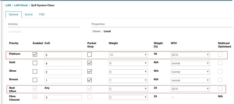
The Platinum QoS System Classes are enabled in this FlashStack implementation. The Cisco UCS and Cisco Nexus switches are intentionally configured this way so that all IP traffic within the FlashStack will be treated as Platinum CoS5. Enabling the other QoS System Classes without having a comprehensive, end-to-end QoS setup in place can cause difficult to troubleshoot issues.
For example, Pure storage controllers by default mark all interfaces nvme-roce protocol packets with a CoS value of 5. With the configuration on the Nexus switches in this implementation, storage packets will pass through the switches and into the UCS Fabric Interconnects with CoS 5 set in the packet header.
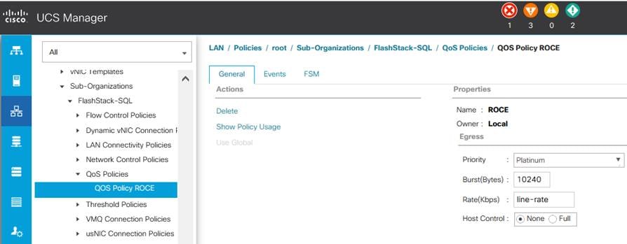
QoS policy for RoCE Traffic
To configure QoS Policy for RoCE Network traffic, follow these steps:
1. Go to LAN > Policies > root > sub-Organization > FlashStack-SQL QoS Policies and right-click for Create QoS Policy.
2. Name the policy as ROCE and select priority as Platinum as shown below:
Figure 22. QoS Policy for RoCE Traffic
BIOS Policy
It is recommended to use appropriate BIOS settings on the servers based on the workload they run. The default bios settings work towards power savings by reducing the operating speeds of processors and move the cores to the deeper sleeping states. These states need to be disabled for sustained high performance of database queries. The following BIOS settings are used in our performance tests for obtaining optimal system performance for SQL Server OLTP workloads on Cisco UCS B200 M5 server. The following figure shows some of the settings that are important to consider for optimal performance.
Figure 23. BIOS Policy
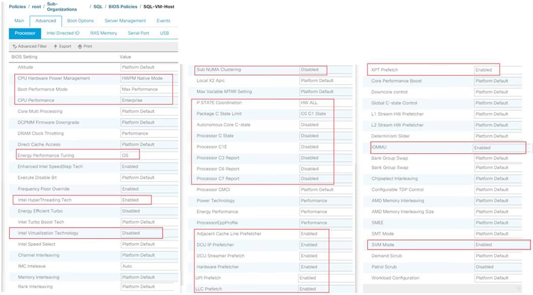
In addition to the above described processor settings, make sure the following BIOS options have been configured as follows:
Click the RAS Memory tab and set LV DDR mode -> Performance mode and Memory RAS Configuration -> Platform Default.
![]() Based on your environment and requirements, set the remaining BIOS settings. The BIOS settings shown above were used for the validation and testing conducted in our labs.
Based on your environment and requirements, set the remaining BIOS settings. The BIOS settings shown above were used for the validation and testing conducted in our labs.
For more details on BIOS settings for Cisco UCS M5 server, see: https://www.cisco.com/c/dam/en/us/products/collateral/servers-unified-computing/ucs-b-series-blade-servers/whitepaper_c11-740098.pdf
Adapter Policy
In this solution, two adapter policies are required as there are different types of traffics each with different priories. One traffic is the public traffic for managing servers and other traffic is the Storage traffic using NVMe protocol Over RoCE which needs be classified as high priority traffic. For this reason, two different adapter policies are required. One Adapter policy for Public traffic and second adapter policy for Storage RoCE traffic as explained in the following sections.
For the public traffic, the default Linux policy is used. The default Linux adapter policy is shown below.
Figure 24. Default Linux Adapter Policy
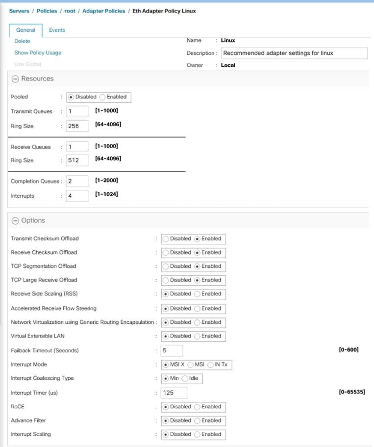
![]() Changes to Transmit and Receive queues are thoroughly tested and validated before using them in the production deployments. Refer to the following link on how to change these values: https://www.cisco.com/c/en/us/td/docs/unified_computing/ucs/ucs-manager/GUI-User-Guides/Network-Mgmt/4-0/b_UCSM_Network_Mgmt_Guide_4_0/b_UCSM_Network_Mgmt_Guide_4_0_chapter_01010.html
Changes to Transmit and Receive queues are thoroughly tested and validated before using them in the production deployments. Refer to the following link on how to change these values: https://www.cisco.com/c/en/us/td/docs/unified_computing/ucs/ucs-manager/GUI-User-Guides/Network-Mgmt/4-0/b_UCSM_Network_Mgmt_Guide_4_0/b_UCSM_Network_Mgmt_Guide_4_0_chapter_01010.html
To create a new adapter policy for Storage RoCE traffic, follow these steps:
1. In Cisco UCS Manager, click the Servers tab in the navigation pane.
2. Select Policies > root > right-click Adapter Policies.
3. Select Create Ethernet Adapter Policy.
4. Provide a name for the Ethernet adapter policy as RoCE_Adapter. Change the fields as shown below and click Save Changes:
Figure 25. New Adapter Policy for Storage Traffic
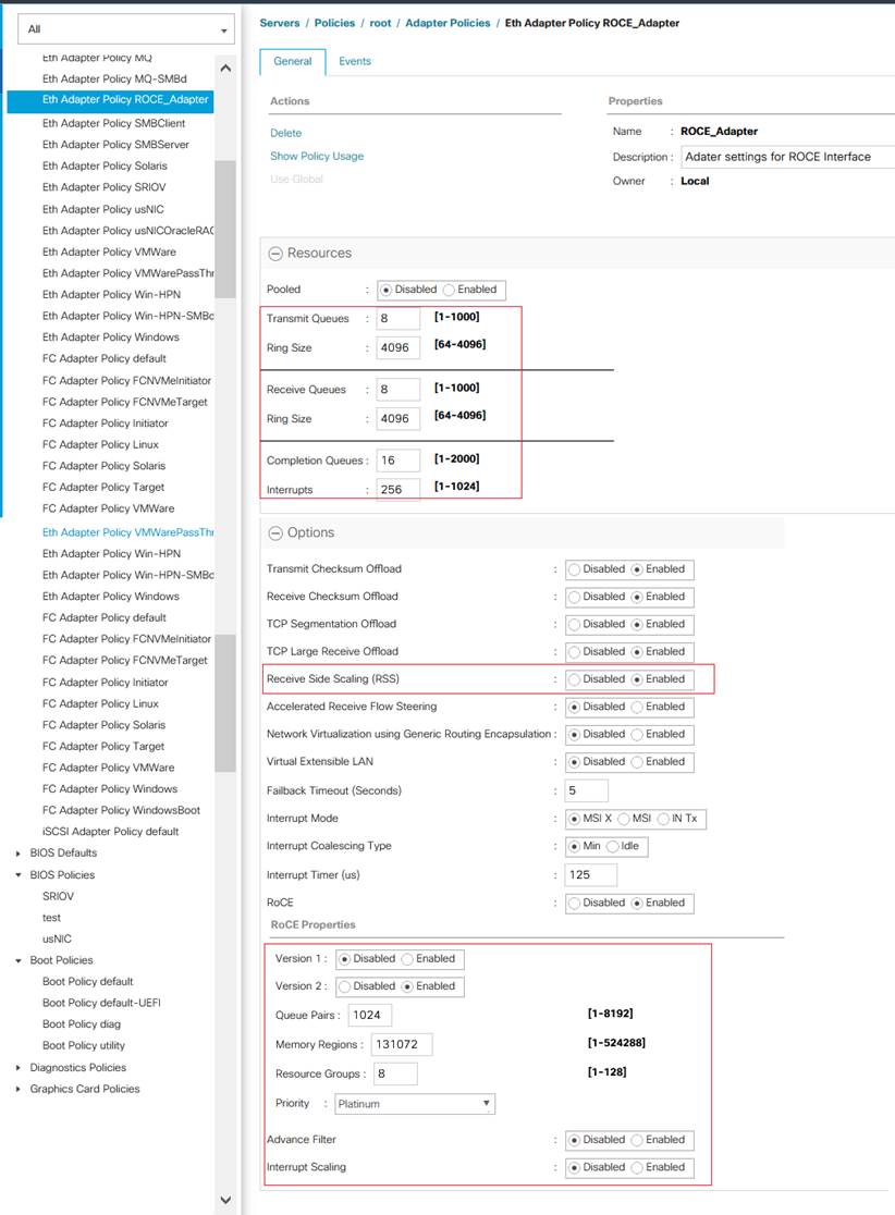
![]() It is not recommended to change values of Queue Pairs, Memory Regions, Resource Groups, and Priority settings other than to Cisco provided default values. You can refer the default Adapter policy “Linux-NVMe-RoCE” under the root organization for the default values for the above settings.
It is not recommended to change values of Queue Pairs, Memory Regions, Resource Groups, and Priority settings other than to Cisco provided default values. You can refer the default Adapter policy “Linux-NVMe-RoCE” under the root organization for the default values for the above settings.
Maintenance Policy Configuration
To update the default Maintenance Policy, follow these steps:
1. In Cisco UCS Manager, click the Servers tab in the navigation pane.
2. Click Policies > root > Maintenance Policies > Default.
3. Change the Reboot Policy to User Ack.
4. Click Save Changes.
5. Click OK to accept the changes.
Create Power Control Policy
To create a power control policy for the Cisco UCS environment, follow these steps:
1. In Cisco UCS Manager, click the Servers tab in the navigation pane.
2. Select Policies > root > Sub Organizations > FlashStack-SQL.
3. Right-click Power Control Policies
4. Select Create Power Control Policy.
5. Enter No-Power-Cap as the power control policy name.
6. Change the power capping setting to No Cap
7. Click OK to create the power control policy.
8. Click OK.
vNIC Templates
Table 14 lists configuration details of the vNICs templates used for this solution for public and storage traffics.
| vNIC Template Name |
Linux-Pub |
Linux_RoCE-A |
Linux_RoCE-B |
| Purpose |
For RHEL Host Management traffic via Fabric-A |
For Storage traffic over RoCE via Fabric-A |
For Storage traffic over RoCE via Fabric-B |
| Setting |
Value |
Value |
Value |
| Fabric ID |
A |
A |
B |
| Fabric Failover |
Enabled |
Disabled |
Disabled |
| Redundancy Type |
No Redundancy |
No Redundancy |
No Redundancy |
| Target |
Adapter |
Adapter |
Adapter |
| Type |
Updating Template |
Updating Template |
Updating Template |
| MTU |
1500 |
9000 |
9000 |
| MAC Pool |
MAC-Pool-A |
MAC-Pool-A |
MAC-Pool-B |
| QoS Policy |
Not-set |
Platinum (Policy ROCE) |
Platinum (Policy ROCE) |
| Network Control Policy |
Not-set |
Not-set |
Not-set |
| Connection Policy: VMQ |
Not-set |
Not-set |
Not-set |
| VLANs |
IB-Mgmt (137) |
ROCE-A (120) |
ROCE-B(130) |
| Native VLAN |
Not-Set |
ROCE-A (120) |
ROCE-B(130) |
| vNIC created |
00-Public |
01-ROCE-A |
02-ROCE-B |
Using the information provided in Table 14, create three network templates: Linux-Public, Linux-ROCE-A and Linux-ROCE-B.
To create network templates, follow these steps:
1. In Cisco UCS Manager, click the LAN tab in the navigation pane.
2. Click Policies > root > Sub Organizations > FlashStack-SQL > vNIC Templates > right-click vNIC Template and select Create vNIC Template.
3. Enter Linux-Public as the vNIC template name and fill up the remaining setting as detailed in the table above. Click Ok to complete the template creation.
4. Create the remaining two templates ( Linux-ROCE-A and Linux-ROCE-B) using the information provided in Table 14.
![]() Fabric failover is not supported on RoCE based vNICs with this release of Cisco UCS Manager and the recommendation is to use the OS level multipathing to reroute and balance the storage network traffic.
Fabric failover is not supported on RoCE based vNICs with this release of Cisco UCS Manager and the recommendation is to use the OS level multipathing to reroute and balance the storage network traffic.
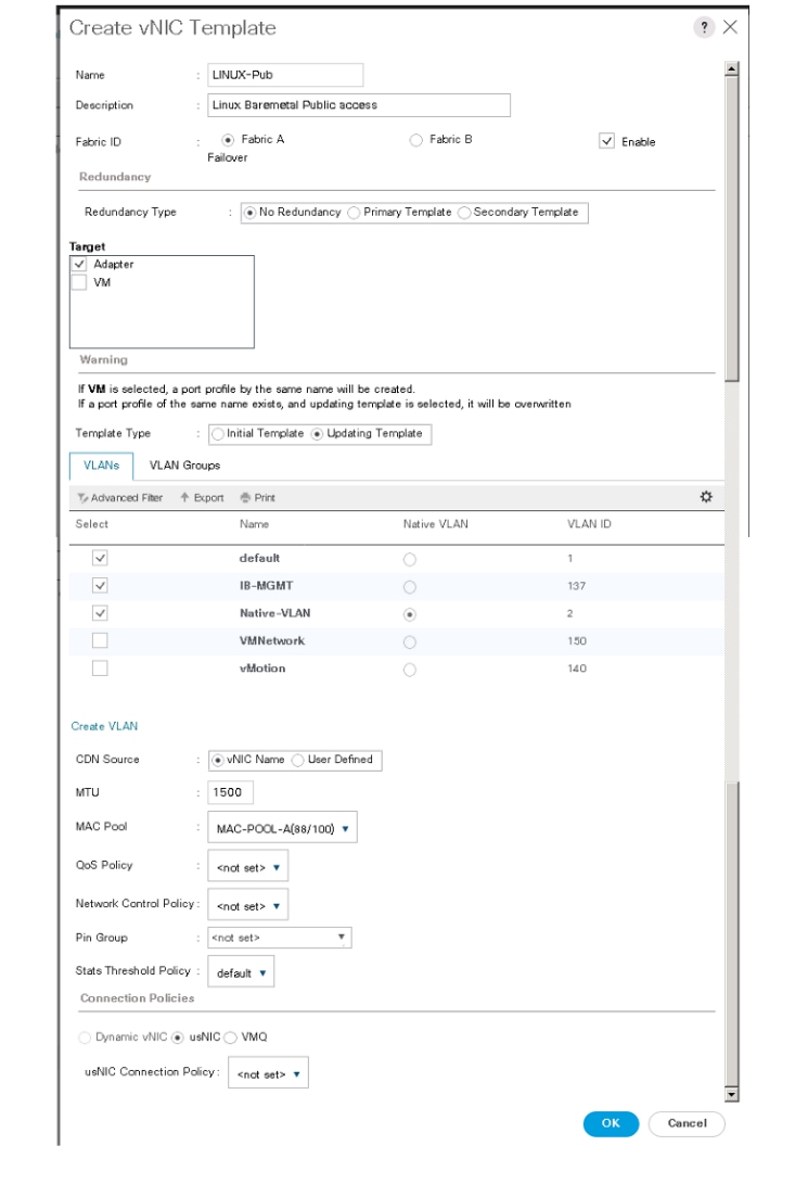
The following figure shows Linux-Public network template created for public traffic.
Figure 26. vNIC Template for Public Traffic
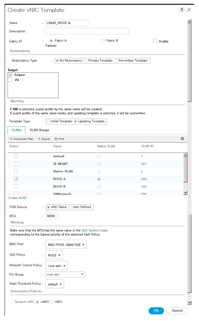
The following figure shows Linux-ROCE-A network template created for storage traffic flows through Fabric Interconnect A.
Figure 27. vNIC Template for Storage Traffic via Fabric A
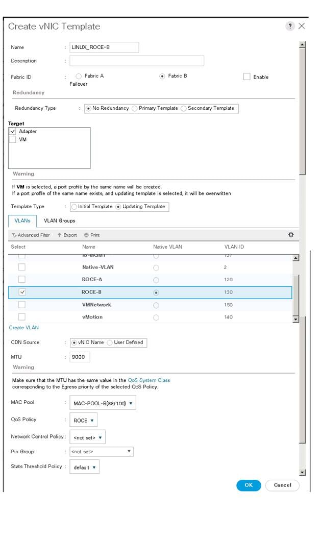
The following figure shows Linux-ROCE-B network template created for storage traffic flows through Fabric Interconnect B.
Figure 28. vNIC Template for Storage Traffic via Fabric B
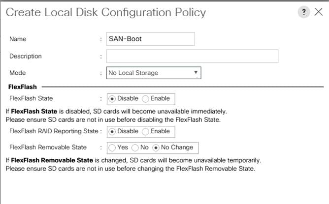
Local Disk Policy (optional)
Since RHEL hosts are configured to boot from SAN, no local disks will be used for any purpose. Create a Local disk policy with the “No Local Storage” option. To create a local disk policy, follow these steps:
1. In Cisco UCS Manager, click the Server tab in the navigation pane.
2. Click Policies > root > Sub Organizations > FlashStack-SQL > right-click Local Disk Config Policies > select Create Local Disk Configuration Policy.
3. Enter SAN-Boot as policy name.
4. Change the mode to No Local Storage as shown below.
5. Click OK to create local disk configuration policy.
Figure 29. Local Disk Configuration Policy for SAN Boot
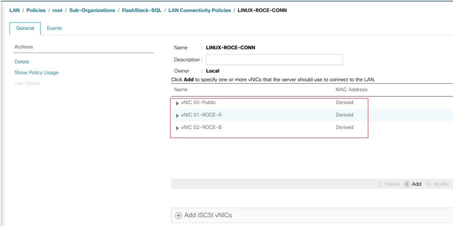
LAN Connectivity Policy
By leveraging the vNIC templates and Ethernet Adapter policies previously discussed, a LAN connectivity policy is created with three vNIC. Every RHEL server will detect the network interfaces in the same order, and they will always be connected to the same VLANs via the same network fabrics.
To create a LAN Connectivity policy, follow these steps:
1. In Cisco UCS Manager, click the LAN tab in the navigation pane.
2. Click Policies > root > Sub Organizations > FlashStack-SQL > right click LAN Connectivity Policy > and select Create LAN Connectivity Policy.
3. Enter Linux-ROCE-Conn as the LAN connectivity policy name
4. Click Add to add vNIC. Enter 00-Public as vNIC name and check the box for Use vNIC Template.
5. Click Linux-Pub for vNIC template and select Linux for Adapter Policy. Click OK to complete adding vNIC for public traffic.
6. Click Add to add second vNIC. Enter 01-ROCE-A as vNIC name and check the box for Use vNIC Template.
7. Click LINUX_ROCE-A for vNIC template and select ROCE_Adapter for Adapter Policy.
8. Click Add to add third vNIC. Enter 02-ROCE-B as vNIC name and check the box for Use vNIC Template.
9. Click LINUX_ROCE-B for vNIC template and select ROCE_Adapter for Adapter Policy.
The final LAN Connectivity policy is shown below.
This LAN Connectivity Policy will be used in the service profile template.
Figure 30. vNICs Derived Using LAN Connectivity Policy
Configure UCS 6454 Fabric Interconnects for FC Connectivity
Cisco UCS 6454 Fabric Interconnects will have a slider mechanism within the Cisco UCS Manager GUI interface that will control the first 8 ports starting from the first port and configured in increments of the first 4 or 8 of the unified ports. In this solution, all 8 ports are enabled but only 4 ports are used for Pure Storage access using the Fibre Channel protocol. The other four ports (5 to 8) are unused, and they can be used for future use.
To enable the fiber channel ports, follow these steps:
1. In Cisco UCS Manager, click the Equipment tab in the navigation pane.
2. Click Equipment > Fabric Interconnects > Fabric Interconnect A (primary).
3. Click Configure Unified Ports.
4. Click Yes on the pop-up window warning that changes to the fixed module will require a reboot of the fabric interconnect and changes to the expansion module will require a reboot of that module.
5. Within the Configured Fixed Ports pop-up window move the gray slider bar from the left to the right to select 5 with either 4 or 8 ports to be set as FC Uplinks.
6. Click OK to continue.
7. Repeat steps 1-6 to configure unified ports on the Fabric Interconnect B.
The following figure shows enabling unified ports on a Fabric Interconnect.
Figure 31. Cisco UCS Unified Port Configuration
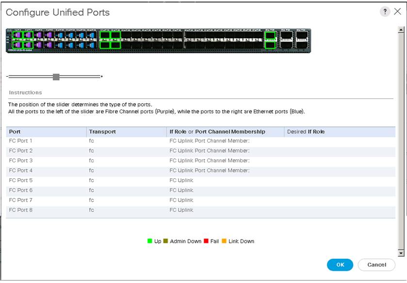
Configure VSANs and Fibre Channel Port Channels
For this solution, two VSANS are used, one for each SAN switching fabric. Table 15 lists the VSANs used for this solution.
| VSAN Name |
VSAN ID |
Fabric |
| FlashStack-VSAN-A |
101 |
A |
| FlashStack-VSAN-B |
201 |
B |
To configure the necessary virtual storage area networks (VSANs) for the Cisco UCS environment, follow these steps:
1. In Cisco UCS Manager, click the SAN tab in the navigation pane.
2. Click SAN > SAN Cloud. Right-click VSANs.
3. Click Create VSAN.
4. Enter VSAN_A as the name of the VSAN to be used for Fabric A
5. Leave Disabled selected for FC Zoning.
6. Click Fabric A.
7. Enter a unique VSAN ID (101) and a corresponding FCoE VLAN ID (101).
8. Click OK and then click OK again to complete the VSAN creation for Fabric-A.
9. Repeat steps 1-8 for creating VSAN_B ( VSAN_ID= 201) for Fabric-B.
The following figure shows the VSAN_B created for Fabric-B.
Figure 32. VSAN Creation on UCS
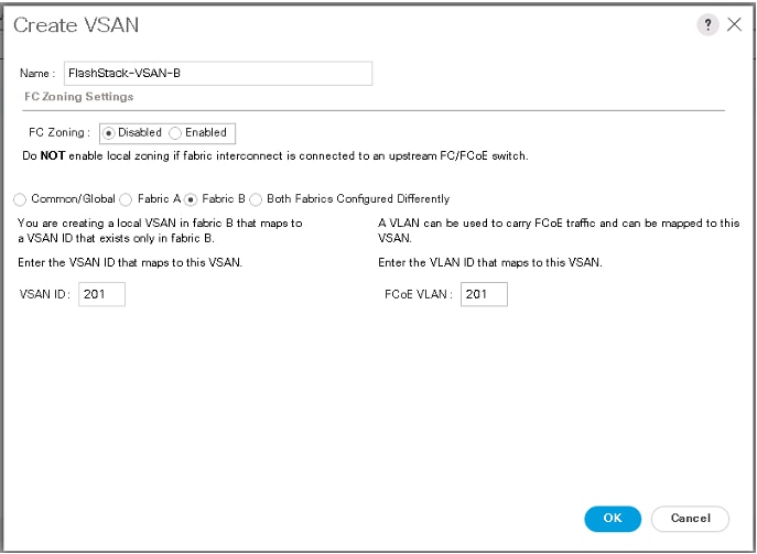
The Fibre Channel Port Channel needs to be configured on each Fabric Interconnect with the Unified Ports that were configured previously. Table 16 lists the FC Port Channels configured for this solution.
Table 16. Fibre Channel Port Channel
| FC Port Channel Name |
Fabric |
FC Interface Members |
VSAN Name/ID |
Aggregated Bandwidth (Gbps) |
| SAN-PO1 |
A |
1/1, 1/2, 1/3 and 1/4 |
FlashStack-VSAN-A/101 |
128 |
| SAN-PO2 |
B |
1/1, 1/2, 1/3 and 1/4 |
FlashStack-VSAN-B/201 |
128 |
To create two Fibre Channel Port Channels, one for each fabric, use the information provided in Table 15 and Table 16, and follow these steps:
1. Go to SAN > SAN Cloud expand the Fabric A tree.
2. Right-click FC Port Channels.
3. Fibre Channel Port Channels Create FC Port Channel.
4. Enter 1 for the ID and SAN-Po1 for the Port Channel name.
5. Click Next then choose appropriate ports and click >> to add the ports to the port channel
6. Click Finish.
7. Click OK.
8. Select the newly created Port-Channel
9. Under the VSAN drop-down list for Port-Channel SAN-Po1, choose FlashStack_VSAN_A/101
10. Click Save Changes and then click OK.
The figure below shows the Fibre Channel Port Channel created on Fabric A.
Figure 33. Fibre Channel Port Channel on Fabric-A
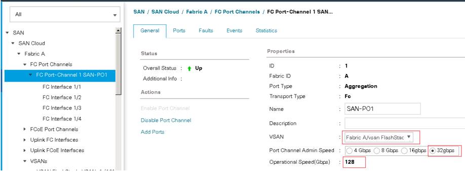
Similarly, create another port-channel for Fabric-B using information provided in the table above. Ensure that the appropriate Port Channel Admin speed is selected, and the aggregated bandwidth is correctly calculated based on the number FC ports that were configured members of the Port Channel.
vHBA Templates
The required virtual Host Bus Adapters (vHBAs) templates are created using the details provided in Table 17.
Table 17. Fibre Channel vHBA Templates
| vHBA Template Name |
vHBA-Template-A |
vHBA-Template-B |
| Purpose |
FC storage access using Fabric - A |
FC storage access using Fabric – B |
| Settings |
Value |
Value |
| Fabric |
A |
B |
| Redundancy Type |
No Redundancy |
No Redundancy |
| VSAN |
FlashStack-VSAN-A/101 |
FlashStack-VSAN-B/201 |
| Template Type |
Initial Template |
Initial Template |
| Max Data Field Size |
2048 |
2048 |
| WWPN Pool |
WWPN-Pool-A |
WWPN-Pool-B |
| QoS Policy |
Not Set |
Not Set |
A sample HBA template for Fabric-A is shown below. Similarly, another HBA template needs to be created using the details provided in Table 17.
Figure 34. HBA-Template for Fabric A
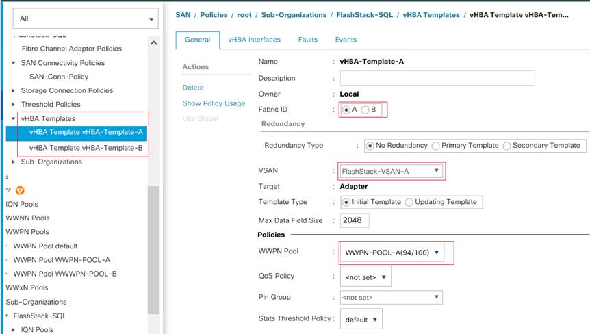
SAN Connectivity Policy
To configure the necessary Infrastructure SAN Connectivity Policy, follow these steps:
1. In Cisco UCS Manager, click the SAN tab in the navigation pane.
2. Click SAN > Policies > root >Sub Organizations > FlashStack-SQL.
3. Right-click SAN Connectivity Policies.
4. Click Create SAN Connectivity Policy.
5. Enter SAN-Conn-Policy as the name of the policy.
6. Select the previously created WWNN_Pool for the WWNN Assignment.
7. Click Add to add a vHBA.
8. In the Create vHBA dialog box, enter Fabric-A as the name of the vHBA.
9. Select the Use vHBA Template checkbox.
10. Leave Redundancy Pair unselected.
11. In the vHBA Template list, select vHBA_Template_A.
12. In the Adapter Policy list, choose Linux. The default Linux FC Adapter policy is sufficient since the Fiber Channel volumes are used only for OS boot; they are not used for storing database files.
13. Click Ok.
The figure below shows how to derive a vHBA from vHBA-Template-A using the SAN Connectivity Policy.
Figure 35. Deriving vHBA from vHBA-Template Using SAN Connectivity Policy
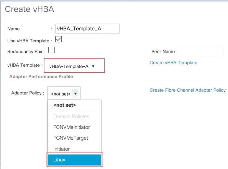
14. Click Add button at the bottom to add a second vHBA
15. In the Create vHBA dialog box, enter vHBA_Template_B for the name of the vHBA.
16. Select the Use vHBA Template checkbox
17. Leave Redundancy Pair unselected.
18. In the vHBA Template list, select vHBA_Template_B.
19. In the Adapter Policy list, select Linux.
20. Click OK.
Two vHBA are derived using the SAN connectivity policy as shown below.
Figure 36. SAN Connectivity Policy with Two vHBAs
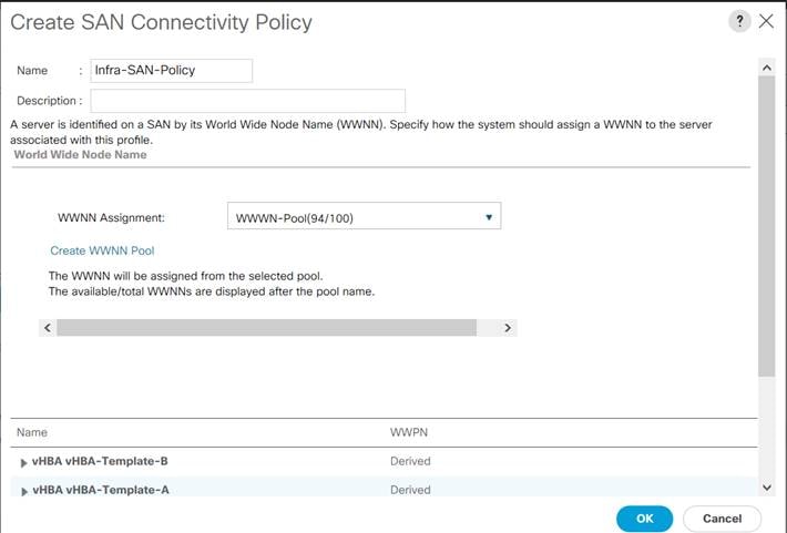
Boot Policy for SAN Boot
For the RHEL hosts to establish connections to the Pure Storage over Fibre Channel, required WWN names of the Pure Storage FlashArray need to be configured in the Boot policy. To gather Primary and Secondary target WWN names (Pure Storage FlashArray//X50 R3 array) and use them to configure the boot policy, follow these steps:
1. To collect the WWN names of Pure Storage FlashArray, log into the Pure storage CLI and run the command to list the ports details of the array as shown below.
Figure 37. Listing Pure Storage Array FC Ports details
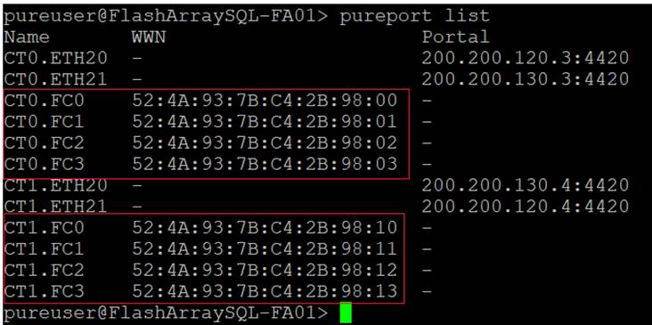
2. An alternative way to collect this information is to logon to the FlashArray’s IP address using a browser and navigate to Health > Connections > Array Ports.
Table 18 lists the information gathered from Pure Storage FlashArray for configuring the Boot Policy. Two target ports are used from each side of Fibre Channel switching fabric.
Table 18. WWNs Names of Pure Storage FlashArray for Boot Policy
| Controller |
Port Name |
Fabric |
Target Role |
WWN Name |
| FlashArray//X50 R3 Controller 0 |
CT0.FC0 |
Fabric-A |
Primary |
52:4A:93:7B:C4:2B:98:00 |
| FlashArray//X50 R3 Controller 1 |
CT1.FC0 |
Fabric-A |
Secondary |
52:4A:93:7B:C4:2B:98:10 |
| FlashArray//X50 R3 Controller 0 |
CT0.FC2 |
Fabric-B |
Primary |
52:4A:93:7B:C4:2B:98:02 |
| FlashArray//X50 R3 Controller 1 |
CT1.FC2 |
Fabric-B |
Secondary |
52:4A:93:7B:C4:2B:98:12 |
To create boot policies for the Cisco UCS environment, follow these steps
1. In Cisco UCS Manager, click the Servers tab in the navigation pane.
2. Click Policies > root >Sub Organizations > FlashStack-SQL.
3. Right-click Boot Policies.
4. Click Create Boot Policy.
5. Enter FC-SAN-Boot as the name of the boot policy. Optionally provide a description for the boot policy.
6. Do not select the Reboot on Boot Order Change checkbox
7. Expand the CIMC Mounted vMedia menu and select Add CIMC Mounted CD/DVD.
8. Expand the vHBAs drop-down list and select Add SAN Boot.
9. In the Add SAN Boot dialog box, enter Fabric-A in the vHBA field.
10. Confirm that Primary is selected for the Type option.
11. Click OK to add the SAN boot initiator.
12. From the vHBA drop-down list, select Add SAN Boot Target.
13. Enter 1 as the value for Boot Target LUN.
14. Enter the WWPN for CT0.FC0 recorded in Table 18.
15. Select Primary for the SAN boot target type.
16. From the vHBA drop-down list, select Add SAN Boot Target.
17. Enter 1 as the value for Boot Target LUN.
18. Enter the WWPN for CT1.FC0 recorded in Table 18
19. Select Secondary for the SAN boot target type.
The following figure shows the target WWNs being added for SAN Boot Fabric-A.
Figure 38. Fabric-A Target WWNs
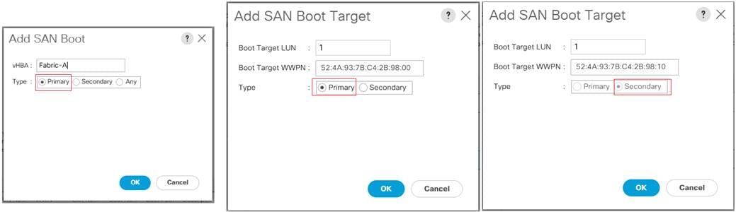
20. From the vHBA drop-down list, select Add SAN Boot.
21. In the Add SAN Boot dialog box, enter Fabric-B in the vHBA box
22. From the vHBA drop-down list, select Add SAN Boot Target.
23. Enter 1 as the value for Boot Target LUN.
24. Enter the WWPN for CT0.FC2 recorded in Table 18.
25. Select Primary for the SAN boot target type.
26. Click OK to add the SAN boot target.
27. From the vHBA drop-down list, select Add SAN Boot Target.
28. Enter 1 as the value for Boot Target LUN.
29. Enter the WWPN for CT1.FC2 recorded in Table 18.
30. Click OK to add the SAN boot target.
The following figure shows the target WWNs being added for SAN Boot Fabric-B.
Figure 39. Fabric-B Target WWNs
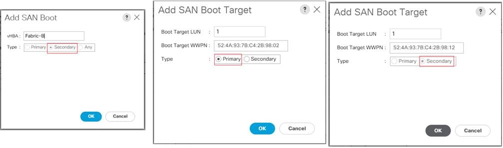
31. Click OK, then click OK again to create the boot policy.
The final Boot Policy is shown below.
Figure 40. Boot Policy for FC SAN Boot
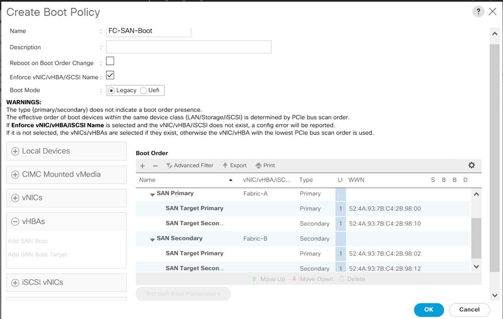
This boot policy will be used by the Service profile templates as discussed in the following sections.
Service Profile Templates Configuration
Service profile templates enable policy-based server management that helps ensure consistent server resource provisioning suitable to meet predefined workload needs.
The Cisco UCS service profile provides the following benefits:
● Scalability - Rapid deployment of new servers to the environment in a very few steps.
● Manageability - Enables seamless hardware maintenance and upgrades without any restrictions.
● Flexibility - Easy to repurpose physical servers for different applications and services as needed.
● Availability - Hardware failures are not impactful and critical. In rare case of a server failure, it is easier to associate the logical service profile to another healthy physical server to reduce the impact.
To create a service profile template, follow these steps:
1. In the Cisco UCS Manager, go to Servers > Service Profile Templates > root > Sub Organizations > FlashStack-SQL > right-click to Create Service Profile Template.
2. Enter the Service Profile Template name as Linux-ROCE-FCBoot, select Updating Template for Type and select the UUID Pool (UUID-POOL) that was created earlier, and click Next.
3. Set Local Disk Configuration Policy to SAN-Boot.
4. In the networking window, select Use Connectivity Policy and select LINUX-ROCE-CONN LAN connectivity which was created earlier. Click Next.
5. In the SAN Connectivity window, select Use Connectivity policy and select SAN-Conn-Policy and click Next.
6. In the Zoning window click Next.
7. From the Select Placement list, leave the placement policy as Let System Perform Placement. Click Next.
Figure 41. vNICs/vHBA Placement
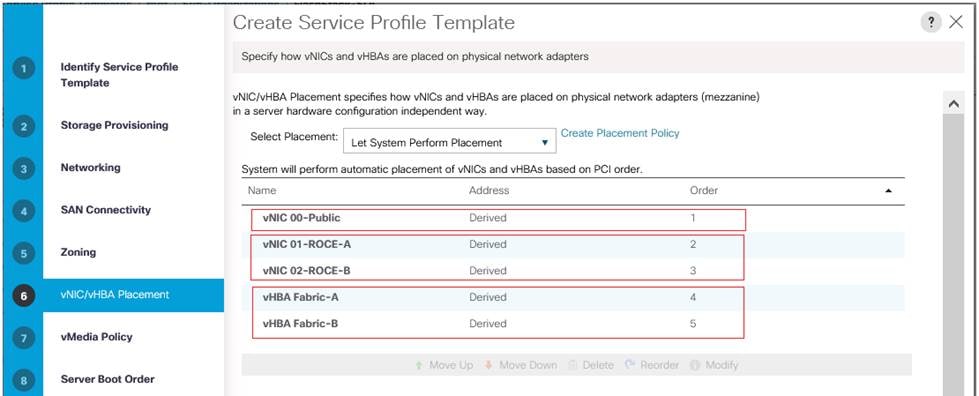
8. Do not select vMedia Policy and click Next.
9. In the Server Boot Order window, select Boot-FC-X-A which was created earlier for SAN boot using Fibre Channel protocol.
Figure 42. Boot Order for FC SAN Boot
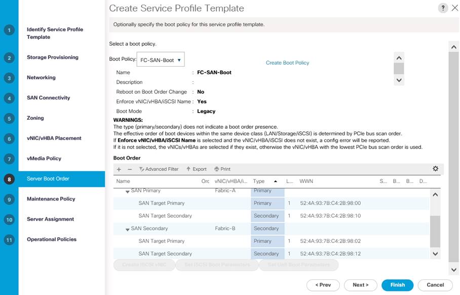
10. In the Maintenance Policy window, select default policy and click Next.
11. In the Server Assignment windows, select infra-Pool for Pool Assignment. Select Down as the power state to be applied when the profile is associated with the server. Click Next.
12. In the Operation Policies window, select BIOS_ROCE for BIOS Policy and No-Power-Cap for Power Control Policy Configuration as shown below.
Figure 43. BIOS and Power Policies
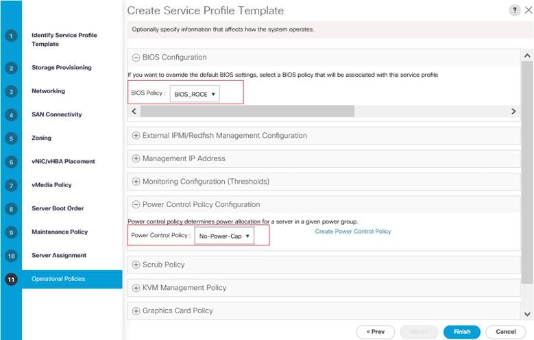
13. Click Finish to complete the Server Profile template creation.
Now you have a service profile template that has three vNICs and two vHBAs as shown below.
Figure 44. vNICs in Service Profile Template
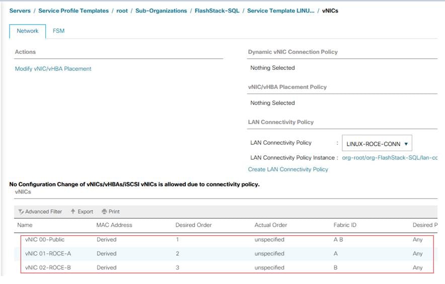
Figure 45. vHBAs in Service Profile Template
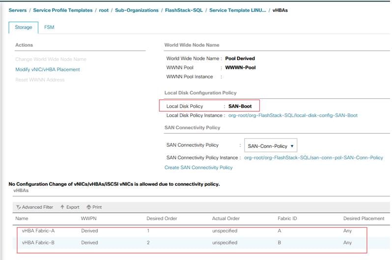
Service profiles Creation and Association
To create two service profiles as LINUX-ROCE-SQL-1 and LINUX-ROCE-SQL-2, follow these steps:
1. Go to tab Servers > Service Profiles > root > Sub Organizations > FlashStack-SQL > right-click Create Service Profiles from Template.
2. Select the Service profile template LINUX-ROCE-FCBoot as previously created and name the service profile LINUX-ROCE-SQL-.
3. To create two service profiles, enter Number of Instances as 2 as shown below. This process will create service profiles as LINUX-ROCE-SQL-1 and LINUX-ROCE-SQL-2.
Figure 46. Service Profile Creation
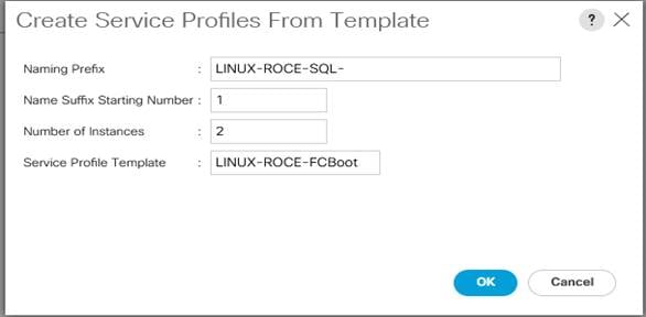
Once the service profiles are created as detailed above, the service profiles will be associated to the available blades automatically as defined in the server pool policy. The service profiles will upgrade the firmware and bios versions of all the components and apply all the server settings as defined in the policies in the service profiles. Once this process completes, make sure all server nodes have no major or critical fault and all are in operable state.
This completes the configuration required for Cisco UCS Manager Setup.
Cisco MDS Switch Zoning Configuration
At this stage, two Cisco UCS B200 M5 blades are configured with required vHBAs and should be ready to establish connections to storage targets to boot from SAN. This section continues the configuration of the Cisco MDS 9132T Multilayer Fabric Switches as resources are attached, to provide zoning for supported devices.
Create Device Alias for better management and Troubleshooting
To create device aliases, follow these steps:
1. Gather the WWPN of the FlashArray adapters using the show flogi database command on each switch and create a spreadsheet to reference when creating device aliases on each MDS. MDS 9132T-A is shown below.
Figure 47. Storage Controller WWNs from Flogi Database on MDS Switch
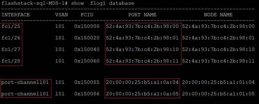
2. Match the values from the individual interfaces to the Purity command line output gained from a ssh connection to the FlashArray using the pureuser account.
Figure 48. Storage Controller WWNs from Pure Array
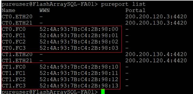
3. Match the values from the port-channel to the UCS Service Profile vHBA listing for each host found within Servers -> Service Profiles -> <Service Profile of Source Host> -> Storage -> vHBAs.
Figure 49. Host WWN Names from Service Profiles
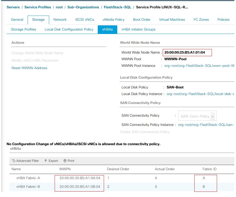
4. Create device alias database entries for each of the PWWNs mapping them to their human readable source names: The following device aliases are created on MDS Switch-A:
configure terminal
device-alias mode enhanced
device-alias database
device-alias name Pure-CT0-FC0 pwwn 52:4a:93:7b:c4:2b:98:00
device-alias name Pure-CT0-FC1 pwwn 52:4a:93:7b:c4:2b:98:01
device-alias name Pure-CT1-FC0 pwwn 52:4a:93:7b:c4:2b:98:10
device-alias name Pure-CT1-FC1 pwwn 52:4a:93:7b:c4:2b:98:11
device-alias name LINUX-ROCE-01-A pwwn 20:00:00:25:b5:a1:0a:04
device-alias name LINUX-ROCE-02-A pwwn 20:00:00:25:b5:a1:0a:05
5. Repeat steps 1-4 on MDS Switch B, starting with gathering the flogi database information.
MDS Zoning
Create zones for each host using the device aliases created in the previous step, specifying initiator and target roles to optimize zone traffic.
To create zoning on the Switch-A the run the following commands:
1. Create zone UCS host: LINUX-ROCE-01-A on MDS Switch A:
configure terminal
zone name LINUX-ROCE-PURE-A vsan 101
member device-alias LINUX-ROCE-01-A initiator
member device-alias Pure-CT0-FC0 target
member device-alias Pure-CT1-FC0 target
member device-alias Pure-CT0-FC1 target
member device-alias Pure-CT1-FC1 target
2. Create zone UCS host: LINUX-ROCE-02-A on MDS Switch A:
configure terminal
zone name LINUX-ROCE-PURE-A vsan 101
member device-alias LINUX-ROCE-02-A initiator
member device-alias Pure-CT0-FC0 target
member device-alias Pure-CT1-FC0 target
member device-alias Pure-CT0-FC1 target
member device-alias Pure-CT1-FC1 target
To create zoning on the Switch-B the run the following commands:
1. Create zone UCS host: LINUX-ROCE-01-B on MDS Switch B:
configure terminal
zone name LINUX-ROCE-PURE-B vsan 201
member device-alias LINUX-ROCE-01-B initiator
member device-alias Pure-CT0-FC2 target
member device-alias Pure-CT0-FC3 target
member device-alias Pure-CT1-FC2 target
member device-alias Pure-CT1-FC3 target
2. Create zone UCS host: LINUX-ROCE-02-B on MDS Switch B:
configure terminal
zone name LINUX-ROCE-PURE-B vsan 201
member device-alias LINUX-ROCE-02-B initiator
member device-alias Pure-CT0-FC2 target
member device-alias Pure-CT0-FC3 target
member device-alias Pure-CT1-FC2 target
member device-alias Pure-CT1-FC3 target
Configuring Zoneset
Add the zones previously created to a zoneset on each MDS switch and activate the zoneset.
To create Zoneset, add zone and active zoneset on MSD Switch-A, run the following commands:
configure terminal
zoneset name Pure-Fabric-A vsan 101
member LINUX-ROCE-PURE-A
zoneset activate name Pure-Fabric-A vsan 101
copy running-config startup-config
To create Zoneset, add zone and active Zoneset on MSD Switch-B, run the following commands:
configure terminal
zoneset name Pure-Fabric-B vsan 201
member LINUX-ROCE-PURE-B
zoneset activate name Pure-Fabric-B vsan 201
copy running-config startup-config
After zones are created and activated on the MDS switches, the next step is to add the Hosts, create boot volumes and map them to the hosts in the Pure Storage FlashArray.
Configure Hosts and Boot Volumes in Pure Storage FlashArray
The Pure Storage FlashArray//X50 R3 is accessible to the FlashStack, but no storage has been deployed at this point. This section provides the steps for Host registration, boot volume creation, and mapping the boot volume to each individual host.
To register each host in the Pure Storage FlashArray, follow these steps after logging into the Pure Storage Purity GUI:
1. Click Storage > Hosts and click the + icon in the Hosts Panel. After clicking the Create Host (+) option, a pop-up will appear to create an individual host entry on the FlashArray
2. To create more than one host entry, click the Create Multiple… option, filling in the Name, Start Number, Count, and Number of Digits, with a “#” appearing in the name where an iterating number will appear.
Figure 50. Creating Host(s) in Pure Storage FlashArray
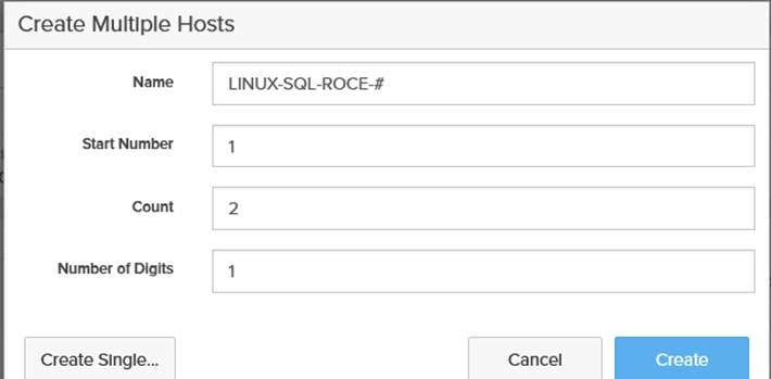
3. Click Create to add the hosts.
4. For each host created, select the host.
5. In the Host view, select Configure WWNs… from the Host Ports menu.
A pop-up will appear for Configure Fibre Channel WWNs <host being configured>. Within this pop-up, select the appropriate existing WWNs from the list. Or you may enter the WWN manually by selecting the +.
Figure 51. Configuring WWNs to Host
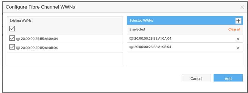
6. After entering the PWWN/WWPN, click Add to add the Host Ports.
7. Repeat steps 1-6 for each host created.
To create private boot volumes for each RHEL Host, follow these steps in the Pure Storage Web Portal:
1. Select Storage > Volumes.
2. Select the + icon in the Volumes Panel.
3. A pop-up will appear to create a volume on the FlashArray. Enter a name and size for the boot volume.
Figure 52. Creating Boot Volume for RHEL
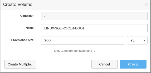
4. To create more than one volume, click the Create Multiple… option, filling in the Name, Provisioned Size, Staring Number, Count, and Number of Digits, with a “#” appearing in the name where an iterating number will appear.
To map the boot volumes to the Hosts, follow these steps in the Pure Storage Web Portal:
1. Select Storage > Hosts.
2. Click one of the hosts and select the gear icon drop-down list and select the required boot volume within the Connected Volumes window as shown below.
Figure 53. Mapping Boot volume to a Host
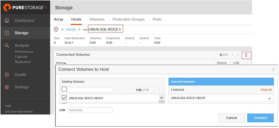
Once the above tasks are done, power on the UCS B200 M5 blades. They will be able to connect to FlashArray boot volumes using the vHBAs configured in the service profiles and should be ready for OS installation.
RHEL Operating System Installation and NVMe/RoCE Configuration
This section explains the steps required for RedHat Enterprise Linux 7.6 Operating System installation. It also explains the configuration steps required for the proper functioning of NVMe storage access over RoCE.
At this stage each Cisco UCS B200 M5 blade server is expected to have successfully discovered and established connections to boot volumes and ready for Operating System installation using bootable ISO media. Figure 54 shows that the Cisco UCS B200 M5 blade server is successfully connected to the boot volumes as previously configured.
RHEL 7.6 Operating System Installation
To install the operating system, follow these steps:
1. Launch KVM console on desired server by going to tab Equipment > Chassis > Chassis 1 > Servers > Server 1 > from right side windows General > and select KVM Console to open KVM.
2. Click Accept security and open KVM. Enable virtual media, map the Red Hat Linux 7.6 ISO image, as shown below, and reset the server.
Figure 54. Boot Volume connectivity and ISO mounting
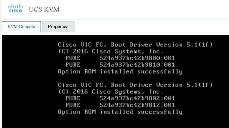
3. When the server starts booting, it will detect the virtual media connected as Red Hat Linux CD. The server should launch the Red Hat Linux installer and we should be able to install the RHEL on the Pure Storage volumes.
4. Select a language and ensure to select the Pure Storage volume for the OS installation. Apply hostname and click Configure Network to configure all network interfaces. Alternatively, you can only configure Public Network in this step. You can configure additional interfaces as part of post install steps.
5. After the OS install, reboot the server, complete the appropriate RHEL subscription registration steps. You can choose to synchronize the time with the ntp server.
For detailed steps for installing RHEL 7.6 Operating Systems, see: https://access.redhat.com/documentation/en-us/red_hat_enterprise_linux/7/html-single/installation_guide/index#chap-simple-install
Configure Public, Private, and Storage Interfaces
If you have not configured the network settings during OS installation, then configure it now. Each node must have a minimum of three network interface cards (NIC), or network adapters. One network interface is for the public network traffic, and the two interfaces for storage network RoCE traffic.
Login as a root user into each node and go to /etc/sysconfig/network-scripts and configure Public network, Storage Network IP Address. Configure the public and storage NICs with the appropriate IP addresses across all the servers. The following figure shows network IP addresses for public (10.29.137.81) and storage (200.200.120.13 and 200.200.130.13) interfaces and MTU set to 9000 for storage interfaces.
Figure 55. IP Address and MTU Configuration
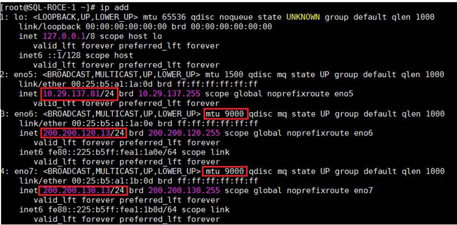
It is important to ensure that Pure Storage FlashArray’s nvme-roce IP addresses are reachable with jumbo frames.
Figure 56. Verifying MTU On the Storage Traffic
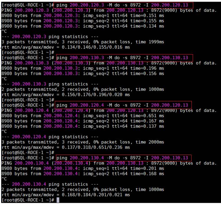
RHEL Host Configuration for NVMeoF with RoCEv2
To configure Linux host and enable RoCE interfaces for storage access over NVMeoF with RoCE, follow these steps:
1. Cisco UCS Manager release 4.1.x and later releases support RoCEv2 on RedHat Enterprise Linux 7.6 with Linux Z-kernel 3.10.0-957.27.2. Upgrade the Linux Kernel to the required version 3.10.0-957.27.2 version by running the following command:
yum update kernel-3.10.0-957.27.2.el7.x86_64
2. Once kernel is successfully upgraded, run the following command to query the kernels that are available to boot from. Ensure that the blade always boots from the updated/latest kernel by setting the default kernel and rebuild the grub file. Finally, reboot the server so the server will boot with the latest kernel.
awk -F\' '$1=="menuentry " {print $2}' /etc/grub2.cfg
grub2-set-default 0
grub2-mkconfig -o /boot/grub2/grub.cfg
3. intel_idle.max_cstate=0 and processor.max_cstate=0 entries are added /etc/default/grub file to disable the CPU c-states and intel_iommu=on is required to enable SRIOV in the kernel. Once the changes are made, rebuild the grub file using grub2-mkconfig -o /boot/grub2/grub.cfg command and reboot the server.
cat /etc/default/grub
GRUB_TIMEOUT=5
GRUB_DISTRIBUTOR="$(sed 's, release .*$,,g' /etc/system-release)"
GRUB_DEFAULT=saved
GRUB_DISABLE_SUBMENU=true
GRUB_TERMINAL_OUTPUT="console"
GRUB_CMDLINE_LINUX="crashkernel=auto rd.lvm.lv=rhel/root rd.lvm.lv=rhel/swap rhgb quiet intel_iommu=on biosdevname=0 intel_idle.max_cstate=0 processor.max_cstate=0 net.ifnames=1"
GRUB_DISABLE_RECOVERY="true"
4. Check the Cisco Hardware Compatibility and ensure that the Cisco UCS VIC1440s enic and enic_rdma drivers are updated to the latest supported versions. When installing enic and enic_rdma drivers, download and use the matched set of enic and enic_rdma drivers on Cisco.com. Attempting to use the binary enic_rdma driver downloaded from Cisco.com with an inbox enic driver, will not work. Run the following command to install/upgrade the enic drivers. Reboot the server after upgrading and verify the correct drivers are loaded by running the commands shown in the following figure.
rpm -ivh kmod-enic-<version>.x86_64.rpm kmod-enic_rdma-<version>.x86_64.rpm
Figure 57. Enic and enic_rdma drivers for Cisco UCS VIC 1440
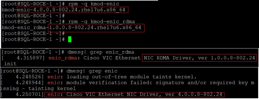
![]() Make sure to use a matching enic and enic_rdma pair. Review the Cisco UCS supported driver release for more information about the supported kernel versions. For Cisco HCL matrix, see: https://ucshcltool.cloudapps.cisco.com/public/
Make sure to use a matching enic and enic_rdma pair. Review the Cisco UCS supported driver release for more information about the supported kernel versions. For Cisco HCL matrix, see: https://ucshcltool.cloudapps.cisco.com/public/
5. Optionally, since the Cisco UCS B200 M5 uses Fibre Channel SAN for booting, it is recommended to update the VIC1440s fnic to the latest and supported version. The same ISO file which was download for upgrading enic and enic_rdma drivers, will also have the matching fnic driver. To Install and verify the fnic driver version in the RHEL OS, run the following commands:
rpm -ivh kmod-fnic-<version>.x86_64.rpm
cat /sys/module/fnic/version
6. Load the nvme-rdma kernel module and in order to load this kernel module on every server reboot, create nvme_rdma.conf file by running the following commands:
modprobe nvme-rdma
echo nvme_rdma > /etc/modules-load.d/nvme_rdma.conf
7. Install nvme-cli version 1.6 or later. Generate host nqn using this tool and store it /etc/nvme/hostnqn file as shown below.
Figure 58. Generating Host nqn

![]() The NVMe Qualified Name (NQN) is used to identify the remote NVMe storage target. It is similar to an iSCSI Qualified Name (IQN). If the file /etc/nvme/hostnqn doesn’t exist, then create the new one and update it as shown above.
The NVMe Qualified Name (NQN) is used to identify the remote NVMe storage target. It is similar to an iSCSI Qualified Name (IQN). If the file /etc/nvme/hostnqn doesn’t exist, then create the new one and update it as shown above.
8. Add this Linux host into Pure Storage FlashArray by logging into the storage array and then navigating to Storage > Hosts > and then click + sign to add host into Pure Storage FlashArray.
9. After creating the host name into storage array, select the created host name. Then go to option Host Ports and then select Configure NQNs. Enter the NQN details from the above Host NQN entry and add the host as shown below for a host RHEL-SQL-ROCE-1.
Figure 59. Creating Host using NQN in Pure Storage FlashArray
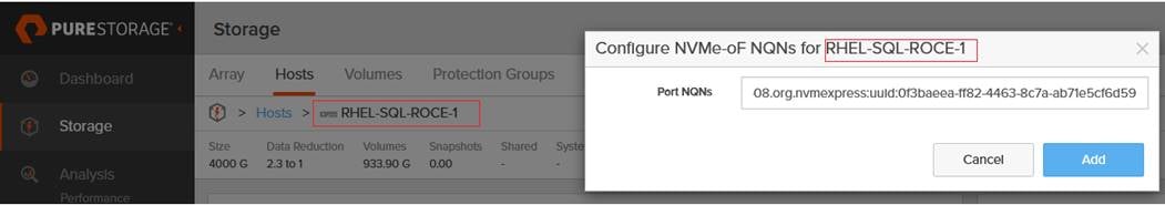
10. Set the Types Of Service (TOS) bits in the IB frames by running the following commands:
for f in `ls /sys/class/infiniband`;
do
echo "setting TOS for IB interface:" $f
mkdir -p /sys/kernel/config/rdma_cm/$f/ports/1
echo 186 > /sys/kernel/config/rdma_cm/$f/ports/1/default_roce_tos
done
11. To make the previous TOS changes permanent and effective even after server reboots, create a /opt/nvme_tos.sh file with the commands as shown below. This file needs to be executed on every server boot. Grant execute permission to this file using chmod command:
cat /opt/nvme_tos.sh
#!/bin/bash
for f in `ls /sys/class/infiniband`;
do
echo "setting TOS for IB interface:" $f
mkdir -p /sys/kernel/config/rdma_cm/$f/ports/1
echo 186 > /sys/kernel/config/rdma_cm/$f/ports/1/default_roce_tos
done
chmod +x /opt/nvme_tos.sh
12. Discover and connect the NVMe devices. After discovering the target NQN ID (using nvme discover command) of the Pure Storage FlashArray, connect to the individual target RoCE interfaces. In order to make the NVMe connections to these storage devices persistent across the server reboots, create a file and add the nvme connect commands for each storage interface as shown below. Grant execute permission to this file in order to execute the file after server reboot:
nvme discover --transport=rdma --traddr=200.200.120.3 ##< IP addresses of transport target port>
Figure 60. Discovering Pure Storage FlashArray NVMe Device
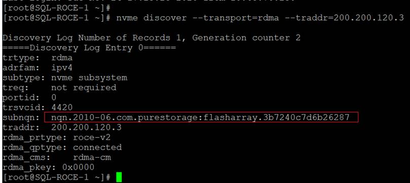
cat /opt/nvme_discover_connect.sh
#!/bin/bash
modprobe nvme-rdma
nvme connect -t rdma -a 200.200.120.3 -n nqn.2010-06.com.purestorage:flasharray.3b7240c7d6b26287
nvme connect -t rdma -a 200.200.120.4 -n nqn.2010-06.com.purestorage:flasharray.3b7240c7d6b26287
nvme connect -t rdma -a 200.200.130.3 -n nqn.2010-06.com.purestorage:flasharray.3b7240c7d6b26287
nvme connect -t rdma -a 200.200.130.4 -n nqn.2010-06.com.purestorage:flasharray.3b7240c7d6b26287
chmod +x /opt/nvme_discover_connect.sh
13. To run the scripts (explained in steps 11 and 12) automatically on each server reboot, create a systemd service and enable it. Use the following commands to create nvme_tos.service service and enable it. Reboot the server once complete:
cat /etc/systemd/system/nvme_tos.service
[Unit]
Description=RDMA TOS persistence
Requires=network.services
After=systemd-modules-load.service network.target
[Service]
Type=oneshot
ExecStart=/opt/nvme_tos.sh
ExecStart=/opt/nvme_discover_connect.sh
StandardOutput=journal
[Install]
WantedBy=default.target
chmod +x /etc/systemd/system/nvme_tos.service
systemctl start nvme_tos.service
systemctl enable nvme_tos.service
Figure 61. Creating Service for Automatic NVMe Device Connectivity
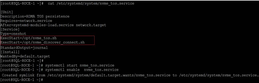
14. Create one or more volumes by logging into the Pure Storage FlashArray, and then navigate to Storage > Volumes > and then click + sign and enter the volume name and size. Click Create to complete the volume creation as shown below.
Figure 62. Creating Pure Storage FlashArray Volume
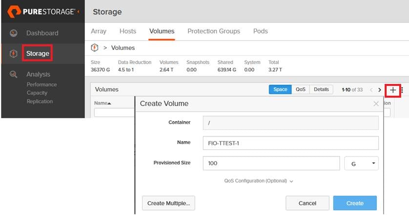
15. Map the volume(s) to the host that was created earlier in steps 8 and 9. Create as many volumes as you need and map them to the host. The figure below shows mapping FIO-TEST-1 volume to the host RHEL-SQL-ROCE-1. Alternatively, you can group the volumes in to a Volume Group, and it can be mapped to the host.
Figure 63. Mapping volume to Host
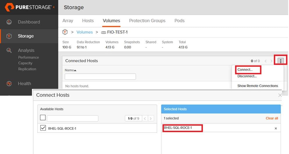
16. Check the nvme list command to check if the NVMe devices from Pure Storage are connected to the host. The figure below shows the two nvme devices with multiple paths to the storage devices.
Figure 64. Listing Pure Storage FlashArray nvme Devices on the Host
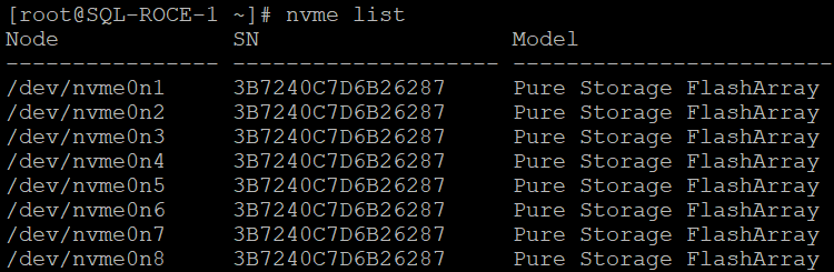
17. To configure the multipath on the host, install device-mapper-multipath package on the host if it is not installed already. Start the multipath service and enable it as shown below. Note the nvme device id by running the multipath -ll command:
mpathconf --enable
systemctl start multipathd.service
systemctl enable multipathd.service
multipath -ll
Figure 65. Retrieving wwid of nvme Device
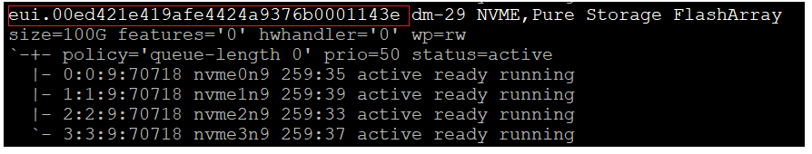
18. The figure below shows the multipath settings used for this solution. Add or edit the /etc/multipath.conf file to include the multipath settings shown below. The figure also shows how to add volume alias names with corresponding wwids for easy identification of volumes. BootVol is connected to the host through Fibre Channel and is used OS boot and rest of the volumes are connected to the host with NVMe/RoCE and used for application testing.
Figure 66. Multipath Configuration
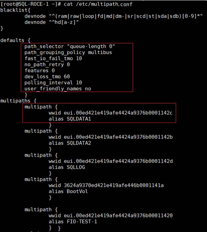
19. The volumes can be partitioned using standard linux tools like fdisk or parted and can be formatted with XFS file system by running the following commands:
Figure 67. Partitioning and Formatting nvme Devices
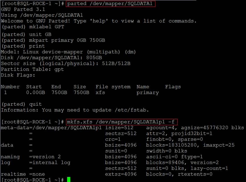
20. In order to mount these volumes automatically on server reboots, the mount commands need be added to a shell script file and it can be invoked from nvme_tos.service file created in step 13. Add the mount commands in /opt/mount_nvme_volume.sh, grant execute permission to the file, and then add an additional entry in nvme_tos.service file as shown below. It is recommended to used -noatime flag for the volumes that are used for storing SQL Server databases.
Figure 68. Partitioning and Formatting nvme Device
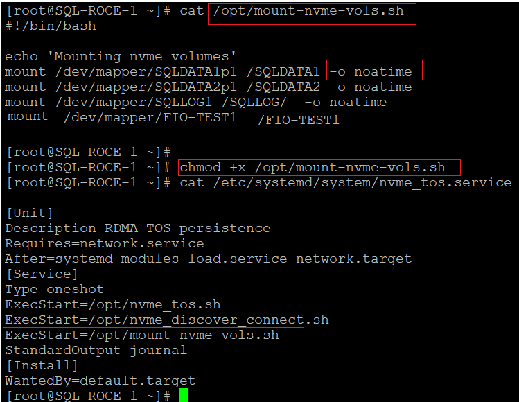
![]() For Pure Storage’s recommendations to configure multipath, see: https://support.purestorage.com/Solutions/Linux/Linux_Reference/Linux_Recommended_Settings
For Pure Storage’s recommendations to configure multipath, see: https://support.purestorage.com/Solutions/Linux/Linux_Reference/Linux_Recommended_Settings
This completes the RHEL host configuration for accessing Pure Storage FlashArray NVMe/RoCE volumes.
Microsoft SQL Server installation and Configuration
This section provides installation and configuration recommendations for Microsoft SQL Server 2019 on a RHEL 7.6 host. For detailed steps to install SQL Server on RHEL, see: https://docs.microsoft.com/en-us/sql/linux/quickstart-install-connect-red-hat?view=sql-server-ver15
To install and configure Microsoft SQL Server, follow these steps:
1. Log into RHLE host as root user to install SQL Server 2019.
2. Install the required Microsoft repo files for installing SQL Server 2019:
sudo curl -o /etc/yum.repos.d/mssql-server.repo https://packages.microsoft.com/config/rhel/7/mssql-server-2019.repo
3. Run the following command to install SQL Server 2019:
yum install -y mssql-server
4. After installation completes, run mssql-conf to select required edition and set the password for SA login. For this documentation, Evaluation Edition (1) is chosen.
/opt/mssql/bin/mssql-conf setup
5. When the setup is complete, enable SQL Server service and verify that SQL service is running by running the following commands:
systemctl enable mssql-server
systemctl status mssql-server
6. Allow the remote connections to SQL Server instance by opening SQL Server ports on the firewall. Run the following commands to open SQL Server default port 1433 permanently:
firewall-cmd --zone=public --add-port=1433/tcp –permanent
firewall-cmd –reload
7. Install SQL Server command-line tools by running the following commands:
sudo curl -o /etc/yum.repos.d/msprod.repo https://packages.microsoft.com/config/rhel/8/prod.repo
yum install -y mssql-tools unixODBC-devel
8. Set the path to SQL Server sqlcmd tool so that you do not have to specify the full path when using sqlcmd tool:
echo 'export PATH="$PATH:/opt/mssql-tools/bin"' >> ~/.bash_profile
echo 'export PATH="$PATH:/opt/mssql-tools/bin"' >> ~/.bashrc
source ~/.bashrc
9. Verify that you are able to connect to SQL Server locally using sqlcmd tool:
sqlcmd -S localhost -U sa -P <sa login Password>
Change Maximum Memory Setting
It is recommended to manually configure memory that SQL Server can consume. If SQL Server process is not restricted, it can consume all the available memory in the system and the system will get in Out Of Memory state. In such cases, SQL Server process will be killed by Operating System. To avoid such scenarios, it is recommended to set maximum memory setting mssql-conf utility. It also important to ensure to leave enough memory for Linux OS and other applications running on the same host for better performance. Typical recommendation is to allocate 80 percent of available memory to the SQL Server process. In large systems with more memory, at least 4GB should be left for OS and adjust the maximum memory setting based on the memory pressure in the system.
Figure 69. Changing SQL Server Maximum Memory Setting
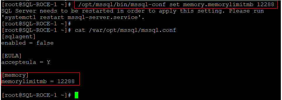
Create Pure Storage FlashArray Volumes for Storing SQL Server Database Files
For storing SQL Server database files on the Pure Storage FlashArray NVMe devices, create one or more volumes with required size in the Pure Storage FlashArray and expose them to the RHEL host that was added using NQN id as explained in the earlier sections. The following figure shows two volumes are created for storing database data files and one volume for storing database log files and mapped to the host RHEL-SQL-ROCE-1.
Figure 70. Attaching Volumes to SQL Host for Storing SQL Server Database Files
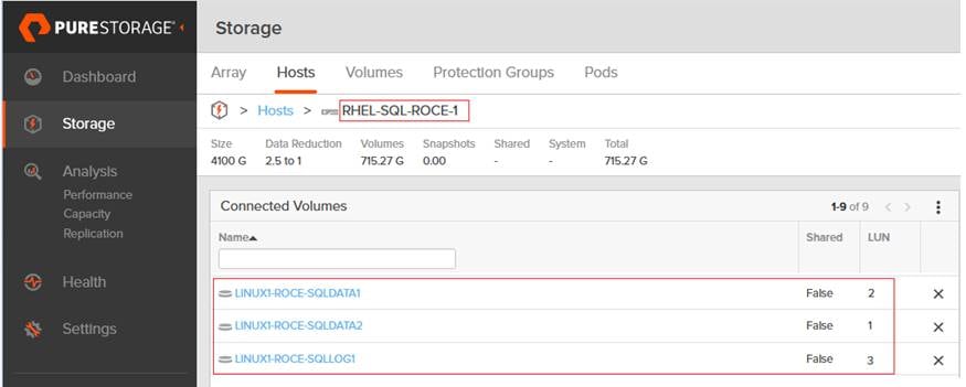
When these volumes are discovered and connected to the host, partition and format the volumes as explained in the previous section. While mounting SQL Server database volume using mount command, use -noatime flag as shown below. For automatic mounting of these SQL volumes on server reboot, add these mount commands into the mount-nvme-vols.sh file as shown in Figure 67 and Figure 68.
mount /dev/mapper/SQLDATA1p1 /SQLDATA1 -o noatime
mount /dev/mapper/SQLDATA2p1 /SQLDATA2 -o noatime
mount /dev/mapper/SQLLOG1p1 /SQLLOG -o noatime
Grant the required permissions on these volumes for SQL Server process to read and write data on these volumes.
chown -hR mssql:mssql /SQLDATA1/
chown -hR mssql:mssql /SQLDATA2/
chown -hR mssql:mssql /SQLLOG/
chgrp -hR mssql /SQLDATA1
chgrp -hR mssql /SQLDATA2
chgrp -hR mssql /SQLLOG
Change Default Database File Locations and Altering tempdb Files
Change the default data and log directory of SQL Server databases to the Pure Storage nvme volumes by running the following commands:
/opt/mssql/bin/mssql-conf set filelocation.defaultdatadir /SQLDATA1
/opt/mssql/bin/mssql-conf set filelocation.defaultlogdir /SQLLOG/
Alter and move the tempdb database data and log files to Pure storage NVMe volumes using Alter database command. The following T-SQL commands configures tempdb with eight data files and one log and stores them on Pure Storage NVMe volumes.
Figure 71. Altering TempDB Files
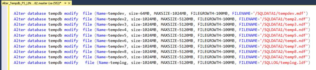
Restart the SQL Server instance for the changes to be effective and verify the status:
systemctl stop mssql-server
systemctl start mssql-server
systemctl status mssql-server
Linux OS configuration for SQL Server
To configure the Operating System with the recommendations for Microsoft SQL Server workloads running on Linux OS, refer to the following links:
Microsoft SQL Server AlwaysOn Availability Groups(AGs)
Microsoft SQL Server supports features such as Failover Cluster Instances (FCI), AlwaysOn Availability Groups (AGs), Log Shipping and Replication and so on, to provide additional availability and data protection to the databases to overcome hardware and software failures. This section details the AlwaysOn Availability Group implementation and testing on FlashStack System.
High Availability and Disaster Recovery solution that customer choose is driven by two end goals: RTO ( Recovery Time Objective) and RPO (Recovery Point Objective). RTO is the duration of acceptable application downtime, whether from unplanned outage or from scheduled maintenance/upgrades. The primary goal is to restore full service to the point that new transactions can take place. RPO defines the ability to accept potential data loss from an outage. It is the time gap or latency between the last committed data transaction before the failure and the most recent data recovered after the failure. For meeting these goals, SQL Server Availability Group is one of the most commonly used approach in many critical production deployments.
The following diagram represents a typical SQL Server Availability Group deployed on a Linux based pacemaker cluster with three replicas.
Figure 72. Typical SQL Server Availability Group Deployment
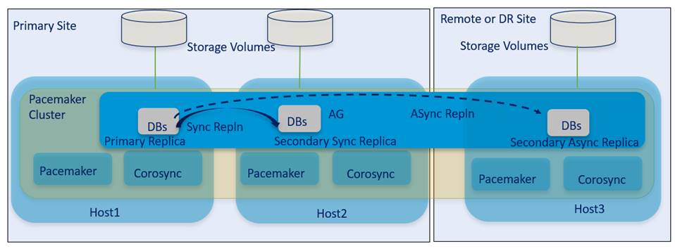
Availability Group does not require shared disk storage and each replica can leverage its local or remote storage independently. The replicas deployed in a primary site are typically aimed to provide high availability to a discrete set of databases from local hardware or protect from software failures. In the primary site, the replicas are configured with synchronous replication in which an acknowledge is sent to a user or application only when the transaction is committed on all the synchronously replicating replicas (log records are hardened). The primary replica is responsible for serving read-write database requests. The remaining synchronous replicas can be configured either in non-readable or read-only mode. Read-Only secondary replicas are used to offload some of the read-only operations (such as reports) and maintenance tasks (such as backup/DB consistency checks) from the primary replica there by reducing the load on the primary replica. In case of unavailability of primary replica due to hardware or software failure, one of the synchronous replicas will be automatically or manually switch over to the primary role quickly and start servicing read-write requests of the users or applications. This synchronous replication mode emphasizes high availability and data protection over performance, at the cost of slight increase in transaction latency as each transaction needs to be committed on all the synchronous replicas. SQL Server 2019 supports up to five (including primary) synchronous replicas.
The replicas deployed in a remote site are typically aimed to provide disaster-recovery to the primary databases in case of complete unavailability of primary datacenter. These replicas are configured with asynchronous replication in which data modifications from primary replica located primary site are asynchronously replicated to the replicas located in remote site. Which means, the data modifications are simply sent to the asynchronous replicas and it is the asynchronous replica’s responsibility to catch up with primary. Hence transaction commit acknowledge does not wait for the confirmation from the asynchronous secondary replica. If the primary site is completely unavailable, the administrator will manually failover the Availability Group to the remote site and recover the customer data.
![]() It is recommended to deploy the synchronous replicas on completely different set of hardware in order to sustain various failures that can occur at different levels such as the blade chassis, Power Strips, and Storage array and so on. It is also important to use similar hardware configurations for secondary synchronous replicas for achieving similar performance when Availability Groups fail over among secondary replicas.
It is recommended to deploy the synchronous replicas on completely different set of hardware in order to sustain various failures that can occur at different levels such as the blade chassis, Power Strips, and Storage array and so on. It is also important to use similar hardware configurations for secondary synchronous replicas for achieving similar performance when Availability Groups fail over among secondary replicas.
For a selection of architecture topologies and the steps to deploy AlwaysOn availability Groups on Linux pacemaker cluster, refer to the following links:
In this solution, AlwaysOn Availability Group is validated using a three-node Linux pacemaker cluster. Two nodes are configured with synchronous replication and one node is configured with asynchronous replication.
Solution Performance Testing and Validation
This section provides a high level summary of the various test results conducted on FlashStack system featuring end-to-end NVMe connectivity between Compute (UCS B200 M5 ) and Storage (Pure Storage FlashArray//X50 R3) via Cisco Nexus 9000 series switches using RoCE.
Table 19 lists the complete details of the testbed setup used for conducting performance tests discussed in the following sections.
Table 19. Hardware and Software Details of Testbed Configuration
| Component |
Device Details |
| Compute |
1x Cisco UCS 5108 blade chassis with 2x Cisco UCS 2408 IO Modules 2x Cisco UCS B200 M5 blades each with 1x UCS 1440 VIC adapter |
| Processor Cores per Cisco UCS B200 M5 blade |
2x Intel® Xeon® Gold 6248 CPUs, 2.5GHz, 27.5MB L3 cache, 20 Cores per CPU |
| Memory per Cisco UCS B200 M5 blade |
384GB (12x 32GB DIMMS operating at 2933MHz) |
| Fabric Interconnects |
2x Cisco UCS 4th Gen 6454 Cisco UCS Manager Firmware: 4.1(1c) |
| Network Switches |
2x Cisco Nexus 9336C-FX2 switches |
| Storage Fabric Switches (optional) |
2x Cisco MDS 9132T Switches (used for booting RHEL hosts from Pure storage using Fibre Channel Protocol) |
| Storage Controllers |
2x Pure Storage FlashArray//X50 R3 with 20 x 1.92 TB NVMe SSDs |
| Storage protocol |
End-to-End NVMe protocol over RoCE (RDMA over Converged Ethernet) |
| Host Operating System |
RedHat Enterprise Linux 7.6 (3.10.0-957.27.2.el7.x86_64) |
| RDBMS Database software |
Microsoft SQL Server 2019 Evaluation Edition CU 6 |
Synthetic IO test with Flexible IO (FIO) Tool
The goal of this test is to demonstrate the calibrated IO capabilities of the FlashStack system for a OLTP like database deployments using FIO tool. FIO tool is a versatile IO workload generator that will spawn several threads or processes doing a particular type of I/O action as specified by the user. For the FIO Tests, we created two volumes on two Cisco UCS B200 M5 blade servers, one volume on each blade. Each blade hosts RedHat Enterprise Linux 7.6 running FIO tool on the volume mounted with NVMe/RoCE protocol. Various FIO tests were executed with 8K block size with different read write ratios for measuring IOPS and Latency which would represent typical OLTP like database deployments.
Figure 73 shows the FIO test results for 8K random IOs with different read-write ratios.
Figure 73. FIO Test Results for 8K Random IOs
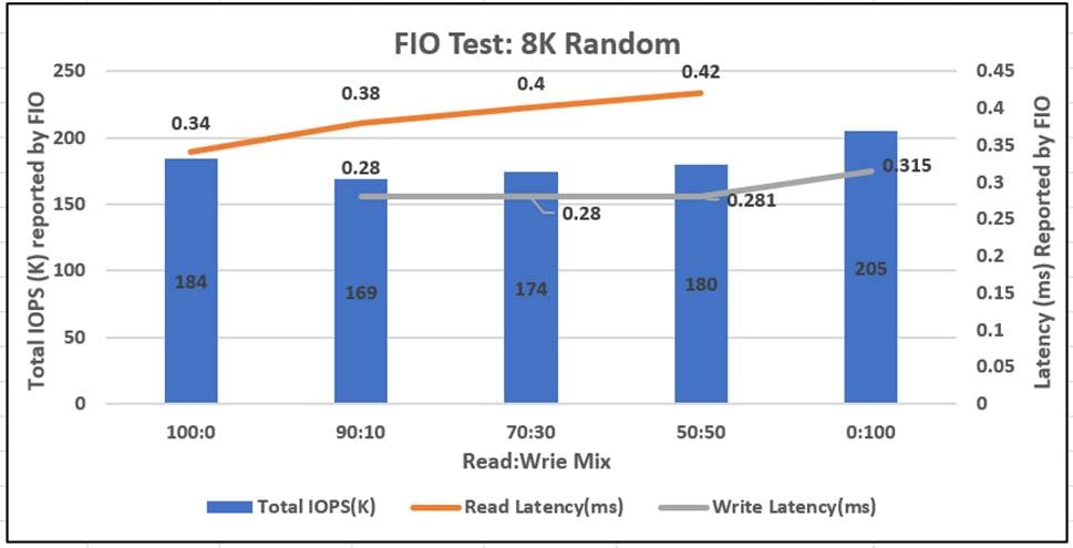
Microsoft SQL Server Database Performance Scalability
This section details the tests conducted on FlashStack system for Microsoft SQL Server OLTP, such as database workloads running on Linux bare metal servers. The goal of this performance validation is to verify if the FlashStack system can deliver required compute and IO performance as demanded by performance critical Microsoft SQL Server database environments. Typically, OLTP workloads are both compute and IO intensive and characterized by a large number of random read and write operations.
Table 20 lists the SQL Server test configuration used for this test.
Table 20. Test configuration for SQL Server Database Performance Scalability Tests
| Component |
Device Details |
| RDBMS |
Microsoft SQL Server 2019 Evaluation Edition CU 6 |
| Database Size |
1x 500GB for 5 to 60 users tests 2x 500GB DBs for 120 user tests (60 users per Database) |
| Database Storage Volumes |
2 x 500GB disk for user database and TempDB data files 1 x 200GB disk for user database and TempDB T-LOG file |
| SQL Server specific tunings |
Maximum Memory=12GB and Maximum Degree of Parallelism (MAXDOP)=6 |
| Testing tool used for SQL Database performance validation |
HammerDB v3.2 |
SQL Server instance is installed on Cisco UCS B200 M5 blade and configured to use all the compute resources available on the blade. SQL Server Max memory setting was purposely set to 12GB so that all the database IO operations will land on Pure Storage FlashArray due to limited SQL buffer cache. Typically, OLTP transactions are small in nature, accessing few database pages quickly and lasting for a very small span of time. Max Degree of Parallelism option allows us to limit the number of processors to use in parallel plan execution. For this performance testing, the MAXDOP set to 6.
![]() MAXDOP value has to be tested thoroughly with your workloads before changing it from the default value (default value is 0). For more detail on MAXDOP, refer to https://docs.microsoft.com/en-us/sql/database-engine/configure-windows/configure-the-max-degree-of-parallelism-server-configuration-option?view=sql-server-ver15#Guidelines.
MAXDOP value has to be tested thoroughly with your workloads before changing it from the default value (default value is 0). For more detail on MAXDOP, refer to https://docs.microsoft.com/en-us/sql/database-engine/configure-windows/configure-the-max-degree-of-parallelism-server-configuration-option?view=sql-server-ver15#Guidelines.
HammerDB tool is used to simulate an OLTP-like database workload for Microsoft SQL Server instances running on the FlashStack system. Various performance metrics were collected during the test execution. Some of the metrics include Transactions Per Second (TPS) from HammerDB, CPU and IO metrics from Linux IOSTATS tool and IO metrics from Pure storage console.
Figure 74 shows test results scalability test conducted on a single Database created within a single SQL Server instance. As shown, as database users scaled up from 5 to 60 on a single database, Transactions Per Minute (TPM) scaled near linearly as the underlying infrastructure was able to provide required performance seamlessly. The CPU utilization of the host also increased gradually as database users scaled.
Figure 74. Performance Scalability within Single Database
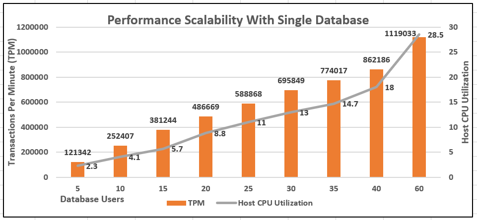
It is a common practice to create more than one database within a single SQL Server instance particularly when there are enough cpu and memory resources freely available within the server hardware. To mimic the real customer scenarios and in order to exercise more stress on the single Cisco UCS B200 M5 blade, two different database sets were created within the same SQL Server instance and each database stressed with 60 users using two different HammerDB instances (one per database). As shown in the figure below, the aggregated TPM of two databases is two times that of single database performance and corresponding increase in host CPU utilization.
Figure 75. Performance Scalability with Two Databases
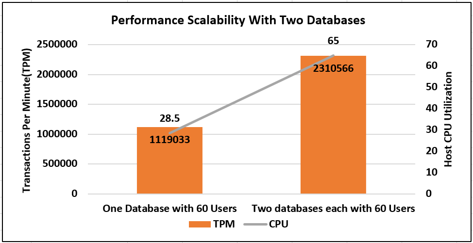
Figure 76 shows the IOPS and latency details for the single database test discussed above captured using IOSTATS Linux utility. As shown, as database users scaled from 5 to 60, IOPS are scaled near linearly with latency under 0.5 milli second.
Figure 76. IOPS Scalability with Single Database
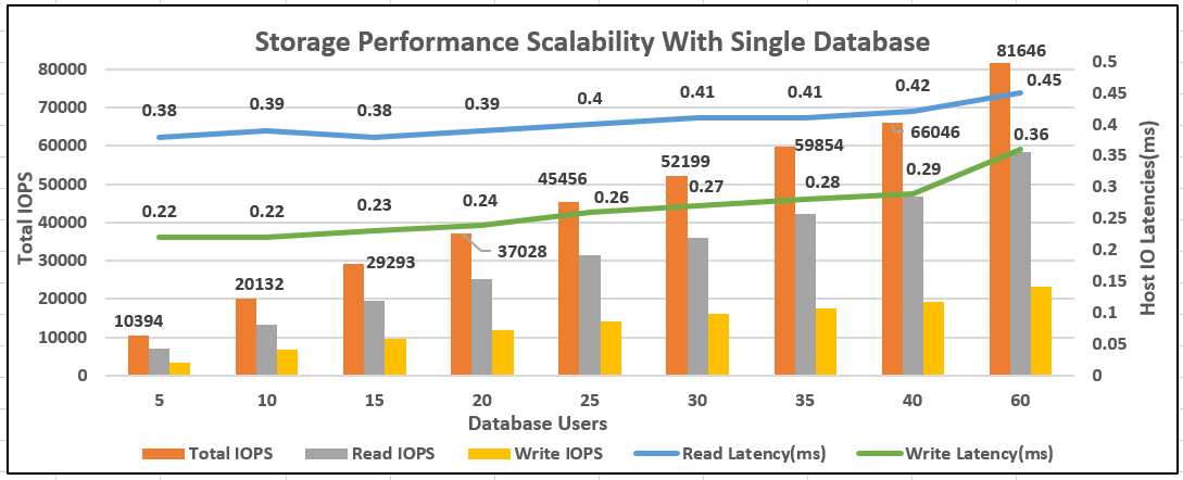
For the two database test, the aggregated IOPS from two databases is 160K which is nearly twice the IOPS of single database test (~81K).
Figure 77. IOPS Scalability with Two Databases
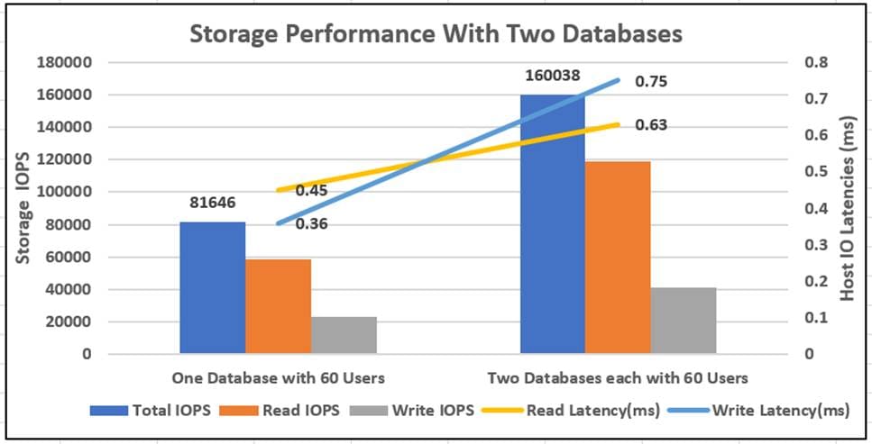
The above test results showed that the FlashStack system featuring end-to-end NVMe connectivity over RoCE was able to deliver consistent compute and high IO operations at sub milli-second latency as demanded by Microsoft SQL Server databases running on bare metal RedHat Linux environments.
Availability Group Validation
This section describes a simplified Availability Groups (AG) deployment to demonstrate the performance of the underlying FlashStack for hosting high performance demanding databases participating in Availability Group. The goal of this test is to provide an estimate of a simplified Availability Group deployment on FlashStack system.
Customers may choose to deploy depending on their business requirement and DR site options available for them. For more information, please refer to Microsoft documentation at: https://docs.microsoft.com/en-us/sql/linux/sql-server-linux-availability-group-overview?view=sql-server-ver15
For this simplified AG deployment, two Cisco UCS B200 M5 blades are used which are located within a single blade chassis each running RHEL operating system with standalone SQL Server instance. Both hosts are connected to the same Pure storage using NVMe/RoCEv2 for storing the databases. These two SQL instances are configured with synchronous replication for providing HA to the databases and act as primary replica. Another standalone SQL Server instance is remotely deployed on a ESXi virtual machine configured with asynchronous replication to receive updates from primary replica. This secondary asynchronous replica is also connected the same Pure storage using Fibre Channel protocol. The following figure illustrates the high-level details of the deployment used for this validation.
Figure 78. High-Level AG Deployment on FlashStack
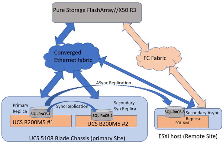
Figure 79 shows a snapshot taken from the SQL Server management studio after configuring the Availability Group in Figure 78.
Figure 79. AG deployment on FlashStack
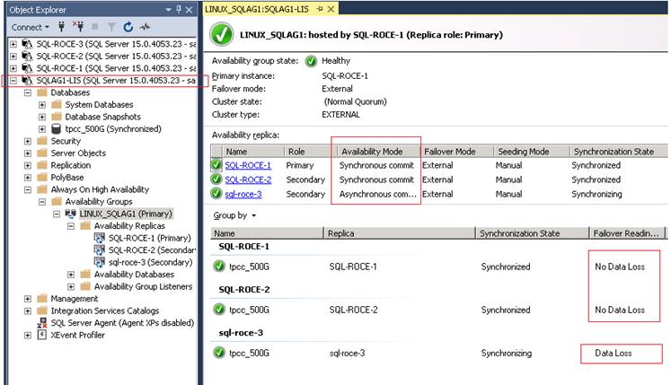
As shown in Figure 79, an Availability Group is configured with two hosts (SQL-RoCE-1 and 2), with synchronous replication and a third replica (SQL-RoCE-3) is configured with asynchronous replication. A 500GB test database is configured to be part of the availability group which can now failover from one replica to another replica if the primary replica is unavailable.
HammerDB tool is used to exercise OLTP-like database workload with 60 users. The following Pure Storage management console shows the IOPS details captured during the test. Since all the three replicas have their databases stored on the Pure storage, the below figure shows consolidated IOPS from all the three replicas. As shown below, the Pure Storage was able to deliver close to 130K IOPS at sub milli second (ms) latency (<0.4ms).
Figure 80. Pure Storage Performance for AG with three-Replicas
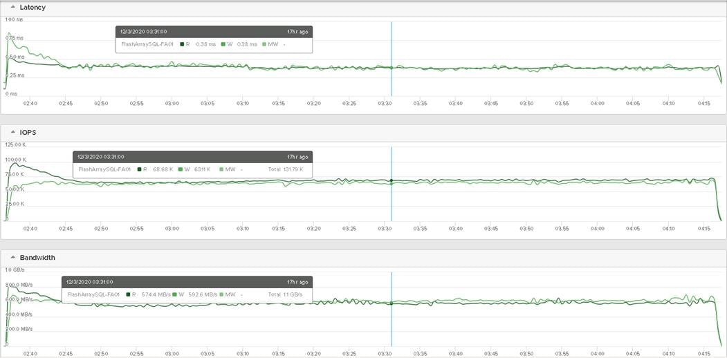
Table 21 lists the IOPS and latency details of three replicas captured using IOSTAT tool for the 60-user test.
Table 21. IO Performance Details of Three Replicas
| Replica and role |
Total IOPS (Read Write ratio) |
Host Read Write Latencies (ms) |
| SQL-RoCE-1 / Primary |
67K at 70:30 RW ratio |
0.45 & 0.48 |
| SQL-RoCE-2 / Secondary (Synchronous replication) |
33.5K at 32:68 RW ratio |
0.71 & 0.65 |
| SQL-RoCE-3 / Secondary (Asynchronous replication) |
33K at 32:68 RW ratio |
0.54 & 0.55 |
Infrastructure Management with Cisco Intersight
Cisco Intersight™ is a cloud-based infrastructure management platform delivered as a service with embedded analytics for your Cisco and third-party IT infrastructure. This platform offers an intelligent level of management that enables IT organizations to analyze, simplify, and automate their environments which are geographical dispersed across the world through a single pane of management interface.
For more information about Cisco Intersight, refer to:
https://intersight.com/help/features
Pure Storage Integration with Cisco Intersight
Cisco Intersight supports management and monitoring of non-Cisco infrastructures such Pure Storage FlashArray. These devices are integrated into Cisco Intersight using a virtual appliance called “Intersight Assist.” Refer to the following links to deploy Intersight Assist Virtual Appliance and integrate the Pure Storage FlashArray and vCenter:
https://www.youtube.com/watch?v=_HSUNCZ2HmY
Pure Storage is the first non-Cisco storage infrastructure integrated into Cisco Intersight. One can add or remove the required storage widgets which provides high level information and insights for the storage arrays being managed by the Cisco Intersight. Figure 81 shows three different storage widgets providing high level information of the Pure Storage FlashArray.
Figure 81. Storage Widgets in Cisco Intersight
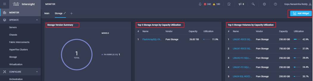
The software and hardware components of Pure Storage FlashArray are presented to Cisco Intersight as objects. Figure 82 shows the details of various objects of Pure Storage FlashArray that are being managed by Cisco Intersight. The General tab shows the high-level details of Pure FlashArray: model, Purity software version, storage capacity utilization reports and the data optimization ratios and so on.
Figure 82. General View of Pure Storage in Cisco Intersight
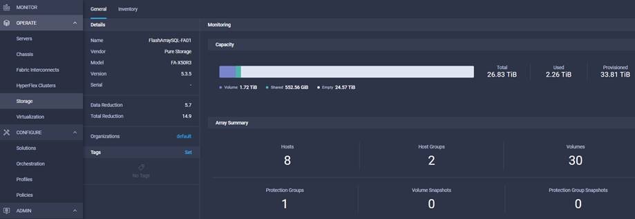
Figure 83 shows the Pure Storage Flash Array software and hardware inventory objects such as Hosts, Host Groups, Volumes, Controllers, Disks, Ports, and so on.
Figure 83. Pure Storage FlashArray Inventory Details in Cisco Intersight
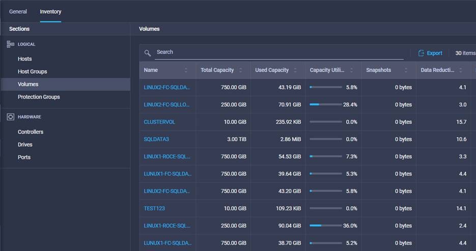
FlashStack is the optimal shared infrastructure foundation to deploy a variety of IT workloads. The solution discussed in this document is built on the latest hardware and software components to take maximum advantage of both Cisco UCS compute and Pure Storage for deploying performance sensitive workloads such as Microsoft SQL Server databases. In addition to the traditional enterprise grade offerings such as snapshots, clones, backups, Quality of Service, by adapting NVMe-oF technologies, this solution extends both Flash and NVMe performance to the multiple servers over traditional ethernet fabrics. This CVD provides a detailed guide for deploying Microsoft SQL Server 2019 databases on RedHat Enterprise Linux 7.6 bare metal environments that uses Pure Storage FlashArray NVMe volumes over RoCEv2. The performance tests detailed in this document validates the FlashStack solution delivering a consistent high throughput at sub millisecond latency required for high performance, mission critical databases.
Cisco UCS hardware and software Compatibility tool:
https://ucshcltool.cloudapps.cisco.com/public/
Pure Storage FlashArray Interoperability (requires a support login form Pure):
https://support.purestorage.com/FlashArray/Getting_Started/Compatibility_Matrix
Cisco Guide for configuring RDMA over Converged Ethernet (RoCE) Version 2:
Cisco Nexus 9000 Series NX-OS Quality of Service Configuration Guide:
Cisco UCS Virtual Interface Card (VIC) Drivers for Linux Installation Guide:
Cisco UCS Manager and Cisco UCS Fabric Interconnects 6454:
https://www.cisco.com/c/en/us/products/servers-unified-computing/ucs-manager/index.html
Cisco UCS 2408 Fabric Extender:
Cisco UCS B200 M5 Blade Server and Cisco VIC 1440:
Cisco Nexus 9336C-FX2 Switch:
https://www.cisco.com/c/en/us/support/switches/nexus-9336c-fx2-switch/model.html
Cisco MDS 9132T Fibre Channel Switch:
Pure Storage FlashArray //X:
https://www.purestorage.com/content/dam/pdf/en/datasheets/ds-flasharray-x.pdf
Pure Storage NVMe Over Fabric Introduction:
https://www.purestorage.com/knowledge/what-is-nvme-over-fabrics-nvme-of.html
Gopu Narasimha Reddy, Technical Marketing Engineer, Compute Systems Product Group, Cisco Systems, Inc.
Gopu Narasimha Reddy is a Technical Marketing Engineer in the Cisco UCS Datacenter Solutions group. Currently, he is focusing on developing, testing, and validating solutions on the Cisco UCS platform for Microsoft SQL Server databases on Microsoft Windows and VMware platforms. He is also involved in publishing TPC-H database benchmarks on Cisco UCS servers. His areas of interest include building and validating reference architectures, development of sizing tools in addition to assisting customers in SQL deployments.
Sanjeev Naldurgkar, Technical Marketing Engineer, Compute Systems Product Group, Cisco Systems, Inc.
Sanjeev has been with Cisco for eight years focusing on delivering customer-driven solutions on Microsoft Hyper-V and VMware vSphere. He has over 18 years of experience in the IT Infrastructure, server virtualization, and cloud computing. He holds a bachelor’s degree in Electronics and Communications Engineering and leading industry certifications from Microsoft and VMware.
For their support and contribution to the design, validation, and creation of this Cisco Validated Design, the authors would like to thank:
● Babu Mahadevan, Cisco Systems, Inc
● John McAbel, Cisco Systems, Inc.
● Vijay Durairaj, Cisco Systems, Inc.
● Hardik Kumar Vyas, Cisco Systems, Inc.
● Craig Walters, Pure Storage, Inc.
● Argenis Fernandez, Pure Storage, Inc.
● Mike Nelson, Pure Storage, Inc.
● Lori Brooks, Pure Storage, Inc.
For comments and suggestions about this guide and related guides, join the discussion on Cisco Community at https://cs.co/en-cvds.