
Cisco TelePresence IX5000 Best Practices: Fit & Finish
June 2015
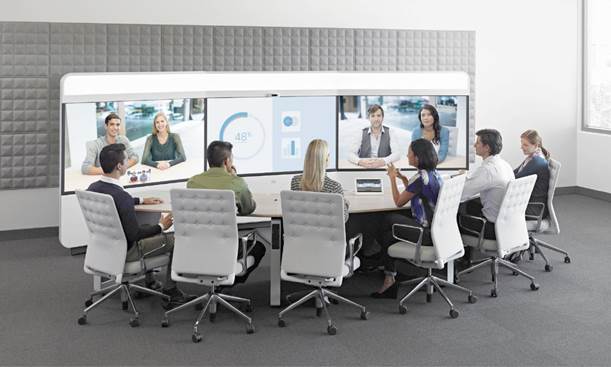
This document was created to outline the best practices for the Cisco TelePresence IX5000 fit and finish considerations. The Cisco TelePresence portfolio has a consistent look and feel throughout, including the latest addition, the IX5000. Attention to detail is of the highest consideration by the Cisco design team. In order for the vision and design details to be recognized at the various partner and customer IX5000 locations, a meticulous and precise effort is required by the installation engineers. The content herein describes the best practices and considerations to produce a superior installation and experience for the end user.
Installation engineers must be equipped with all necessary tools noted in the assembly guide. The list of required tools can be found at the below link, see page 1-4:
http://www.cisco.com/c/dam/en/us/td/docs/telepresence/ix5000/assembly_guide/ix5000_install_guide.pdf
Having access to all required tools is essential. It enables the engineers to perform various mechanical tasks during the IX5000 installation. A good example of this requirement is the laser level with tri-pod. A leveled frame structure is imperative for the cosmetic panels to attach together, seamlessly. See pages 2-1 to 2-16 of the assembly guide for frame structure levelling.
Areas of focus during the IX5000 installation are noted below:
· Top Fascia
· Bottom Fascia
· Horizontal Bezel
· Table Alignment
· Mute Buttons
· Thermoform Panels
· LED Lighting
· Fabric Panels
· General Fit & Finish
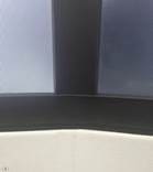
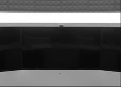
Top Fascia
The top fascia is opaque but optically transparent, extending the full width of the system structure. The top fascia diffuses LED lighting from within the frame structure and also omits from view the inner mechanics of the frame, lights and speakers. Handling of the top fascia must be always performed with gloves, provided by Cisco in the accessory kit. The top fascia should be applied to the frame structure keeping in mind that all outer gaps are even between the fascia edge and the thermoform panels.
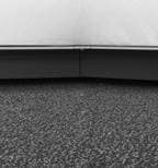
Bottom Fascia
The bottom fascia is a large metal-framed fabric panel protecting the system electronic components and covering the inner frame mechanics. The panel extends the full width of the system structure. Handling of the bottom fascia must always beperformed with gloves. Attach the bottom fascia to the frame so there is an even gap along the top edge and uniform edge on the bottom and sides. Attach the fascia in such a way that the status LED lights on the 70” displays are not visible. Also ensure that all magnet and hook features on the fascia are engaged to the frame structure. This is necessary for a smooth and clean finish.
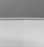
Horizontal Bezel
The horizontal bezel is the rubber trim underneath the displays extending the full width of the system structure. A semi-adhesive film is applied to this part during the manufacturing process to protect it from dust or grease stains. This protective film should remain in place until the end of the install. Do not handle the trim with gloves after the protective film has been removed as the rubber material can attract lint and dust particles. Using the left and right display spool, adjust the spool accordingly so the gap is tight between the display screen and horizontal trim. The trim is a fragile component and must be handled in such a way that the hinge mechanisms are not stressed past the natural installation position for a long period of time. See chapter 15 of the installation guide.

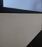
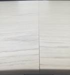
Table Alignment
Careful handling of the table tops is required during delivery and unpacking. To achieve a level surface and uniform table seams, the table legs must be aligned horizontally and vertically with a laser level, prior to the assembly of the table tops. Also ensure the table legs are leveled against the diamond markers on the main endpoint frame. The level markers on both the frame and table legs should be in plane. In some cases, table tops may shrink or expand incrementally due to humid or frigid temperatures during transportation. This could cause minor alignment defects. Some light shimming underneath the table can be an effective resolution in such cases. Under no circumstances should any attempt be made to re-fabricate the table tops by sanding down or cutting. See chapter 7-7 of the intallation guide.
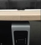
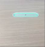
Mute Buttons
There is one mute button per table segment. The mute button is attached to the table top using two M4 screws. The intent is for the mute button to be flush-mounted with the table top surface. Under-tightening the two screws will leave the mute button above the table surface. Over-tightening the two screws will leave the mute button below the table surface. Visually and with your hand, the engineer should verify the correct mounting position of each mute button, looking for a smooth transistion from the table surface to the mute button surface.

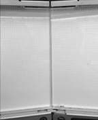
Fabric Panels
There are several types of fabric panels on the system structure and system table area. Please use the gloves provided when handling fabric panels at all times. The various panels are attached using magnet or hook features. It is important that all panels attached are level and seamless. Careful consideration must be taken to ensure that all outer edge gaps are uniform.
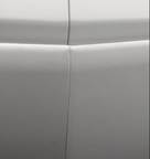

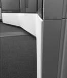
Thermoform Panels
Thermofrom panels require minimal screw attachment; however, they do rely on precise placement from the installation engineer. All gaps along the aluminum extrusion must be tight and uniform. Correct installation of the mechanical structure and related hardware is necessary to achieve this.
LED Lighting
Three LED light panels are installed behind the Top Fascia. The Top Fascia diffuses this light to create an even and seamless lighting effect. If the LED panels are installed in such a way where there is a gap between each panel, this will create a visible shadow seam on the Top Fascia when illuminated. Installation engineers should ensure that all three LED panels are pushed together to prevent this.
Fit & Finish
Use of excessive force is not necessary to join together any mechanical component during installation of IX Series systems. In some cases, there will be tight fitting components, but this is likely an indication of a possible installation error or a fabrication defect. Above all, it is essential to double check the installation process to confirm a root cause for any suspected issues.

![]()