Deployment Details
Two DRaaS service offerings need to considered: SP to Enterprise and vPC to vPC. Each DRaaS service offering will support partial failovers through a L2 extension technology such as OTV. In the vPC-to-vPC use case, we add LISP to provide support for VM mobility between vPC data centers.
Using OTV or LISP in DRaaS
In addition to DRaaS partial failover, OTV can be used for server-to-server communication when an application requires non-IP (L2) communication such as link-local multicast or non-IP unicast communication between servers. Today, most applications in this category are clustered applications. For such applications, a LAN must be extended between the various locations in which the application member servers reside. OTV provides the tools to extend a LAN in a secure manner to support this non-IP traffic.
•![]() LISP is required to provide optimal routing while supporting mobility and location independence in the virtual data center.
LISP is required to provide optimal routing while supporting mobility and location independence in the virtual data center.
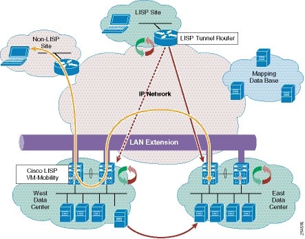
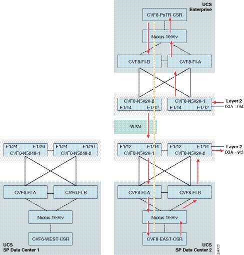
•![]() Use OTV and LISP together to offer live virtual machine mobility and distributed clusters. Applications requiring link-local multicast communication among servers are usually clustered applications that use simple link-local multicast mechanisms for peer discovery as well as for the exchange of hello messages and heartbeat signals. Note that the dispersion of the cluster members could be the result of virtual machine movement across sites with virtual machine mobility tools such as VMware vMotion or simply a static distribution of the servers. Regardless of how the cluster members are distributed, the link-local multicast traffic is required by the clustered application independent of any use of virtualization, as shown in Figure 5-1.
Use OTV and LISP together to offer live virtual machine mobility and distributed clusters. Applications requiring link-local multicast communication among servers are usually clustered applications that use simple link-local multicast mechanisms for peer discovery as well as for the exchange of hello messages and heartbeat signals. Note that the dispersion of the cluster members could be the result of virtual machine movement across sites with virtual machine mobility tools such as VMware vMotion or simply a static distribution of the servers. Regardless of how the cluster members are distributed, the link-local multicast traffic is required by the clustered application independent of any use of virtualization, as shown in Figure 5-1.
Figure 5-1 Inter-Datacenter Traffic in a DRaaS Partial Failover

A DRaaS partial failover would result in some members of clusters being dispersed across multiple locations, so the LAN needs to be extended across these locations to support the forwarding of the non-IP traffic used for peer-discovery and heartbeats. OTV provides the necessary functions to extend a LAN across multiple sites and to support this non-IP communication between servers in the cluster.
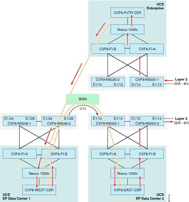
In a vPC-to-vPC partial or complete failover, the mobility of VMs between data centers may need to communicate with clients external to the data center. Since the LAN has been extended across multiple locations, the IP subnet associated with this LAN is also extended across these locations. In this case, the subnet no longer retains its location semantics because a subnet traditionally indicates a single location, but this one is extended across many locations. Traditional routing would not know at which of all the locations in the extended subnet a server may be located, resulting in many cases of suboptimal routing to the servers, as shown in Figure 5-2.
Figure 5-2 Optimal Routing with LISP
When subnets are extended, LISP is instrumental in handling location information at many levels of detail to provide the shortest-path routing to the appropriate locations within the extended subnet and avoid sub-optimal traffic patterns such as the one illustrated above. Thus, LISP adds location semantics to an extended subnet that otherwise would not have any location semantics.
The combination of LISP and OTV provide a complementary approach to distribution of applications across multiple locations while preserving optimal routing to every member of the application. Live VMware vMotion is also supported by this combination of LISP and OTV, which not only supports the application requirements, but helps ensure optimal reachability of the roaming virtual machine wherever it moves.
OTV Implementation
This section describes various features, traffic flows, and configuration options with OTV in the DRaaS System architecture.
OTV Control Plane—The OTV can be implemented in unicast or multicast mode. The OTV control plane works generally the same way in both. The only difference is that in unicast mode each OTV device creates multiple copies of each control plane packet and unicast them to each remote OTV device part of the same logical overlay. The operational simplification brought by the unicast-only model is preferred in scenarios where LAN extension connectivity is required only between few (2-3) DC sites. See Appendix for unicast mode OTV configuration.
Interface Configuration—The interfaces can be configured in multiple ways on the CSR1000v. Use separate L3 interfaces for each VLAN. This limits the number of VLANs that can be used on CSR as version 3.10S supports ten vNICs (VMXNET3) per VM instance.
interface GigabitEthernet3
description VLAN 2121 Layer 3 Interface
ip address 86.21.21.2 255.255.255.0
standby 0 ip 86.21.21.1
load-interval 30
negotiation auto
lisp mobility vlan2121
lisp extended-subnet-mode
arp timeout 1500
Single interface with L3 sub-interfaces for each VLAN. This option scales better with VLANs.
interface GigabitEthernet4
mtu 9000
no ip address
negotiation auto
!
interface GigabitEthernet4.161
encapsulation dot1Q 161
ip address 192.168.11.4 255.255.255.0
no ip proxy-arp
ip pim sparse-dense-mode
standby version 2
standby 11 ip 192.168.11.1
lisp mobility lisp_esm11
lisp extended-subnet-mode
Use single L2 interface with BDI interfaces. This option is not currently supported on 3.10S.
The routed packets loop twice on CSR in first two options. The packets ingress on L3 interfaces, egress on routed L3 interface, ingress on L2 interface and then egress over the OTV. It didn't seem to have any impact on throughput. For more details, see Inter and Intra VLAN traffic flow sections.
Intra-VLAN Flows—These are LAN extension flows between two data centers over OTV. Packets ingress on the L2 interface of CSR in one data center and then are forwarded to these other data center over OTV. The packets egress on L2 interface of CSR in the other data center. The traffic flow path will be as shown in Figure 5-3.
Figure 5-3 Intra-VLAN Flows
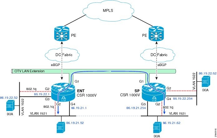
The bridge table and mac entries for the given IP addressing in Figure 5-3 on two CSR would be as follows:
Enterprise CSR
ENT-t19-csr1#sh otv arp-nd-cache
Overlay19 ARP/ND L3->L2 Address Mapping Cache
BD MAC Layer-3 Address Age (HH:MM:SS) Local/Remote
1921 0000.0261.2433 86.19.21.62 00:00:46 Remote
1921 0050.568f.6324 86.19.21.254 00:00:43 Remote
ENT-t19-csr1#sh bridge-domain
Bridge-domain 936 (1 ports in all)
State: UP Mac learning: Enabled
Aging-Timer: 300 second(s)
GigabitEthernet2 service instance 936
MAC address Policy Tag Age Pseudoport
FFFF.FFFF.FFFF flood static 0 OLIST_PTR:0xe8ece400
Bridge-domain 1921 (2 ports in all)
State: UP Mac learning: Enabled
Aging-Timer: 1800 second(s)
GigabitEthernet2 service instance 1921
Overlay19 service instance 1921
MAC address Policy Tag Age Pseudoport
001B.24E0.5F4E forward static_r 0 OCE_PTR:0xea32dc00
0050.5687.1FB2 forward dynamic_c 1681 GigabitEthernet2.EFP1921
0050.568F.6324 forward static_r 0 OCE_PTR:0xea32dc00
0000.0260.D8D1 forward dynamic_c 1800 GigabitEthernet2.EFP1921
0000.0261.2433 forward static_r 0 OCE_PTR:0xea32dc00
FFFF.FFFF.FFFF flood static 0 OLIST_PTR:0xe8ece450
Bridge-domain 1922 (2 ports in all)
State: UP Mac learning: Enabled
Aging-Timer: 1800 second(s)
GigabitEthernet2 service instance 1922
Overlay19 service instance 1922
MAC address Policy Tag Age Pseudoport
FFFF.FFFF.FFFF flood static 0 OLIST_PTR:0xe8ece460
0050.5687.35F7 forward dynamic_c 1684 GigabitEthernet2.EFP1922
ENT-t19-csr1#sh ip arp
Protocol Address Age (min) Hardware Addr Type Interface
Internet 86.19.21.1 - 0050.5687.1fb2 ARPA GigabitEthernet7
Internet 86.19.22.1 - 0050.5687.35f7 ARPA GigabitEthernet8
Internet 86.19.23.1 - 0050.5687.438b ARPA GigabitEthernet9
ENT-t19-csr1#sh otv route
Codes: BD - Bridge-Domain, AD - Admin-Distance,
SI - Service Instance, * - Backup Route
OTV Unicast MAC Routing Table for Overlay19
Inst VLAN BD MAC Address AD Owner Next Hops(s)
----------------------------------------------------------
0 1921 1921 0000.0260.d8d1 40 BD Eng Gi2:SI1921
0 1921 1921 0000.0261.2433 50 ISIS SP-t19-csr1
0 1921 1921 001b.24e0.5f4e 50 ISIS SP-t19-csr1
0 1921 1921 0023.8b03.759f 50 ISIS SP-t19-csr1
0 1921 1921 0050.5687.1fb2 40 BD Eng Gi2:SI1921
0 1921 1921 0050.568f.6324 50 ISIS SP-t19-csr1
0 1922 1922 0050.5687.35f7 40 BD Eng Gi2:SI1922
7 unicast routes displayed in Overlay19
----------------------------------------------------------
7 Total Unicast Routes Displayed
Service Provider CSR
SP-t19-csr1#sh otv arp-nd-cache
Overlay19 ARP/ND L3->L2 Address Mapping Cache
BD MAC Layer-3 Address Age (HH:MM:SS) Local/Remote
1921 0000.0260.d8d1 86.19.21.52 00:00:55 Remote
SP-t19-csr1#sh bridge-domain
Bridge-domain 936 (1 ports in all)
State: UP Mac learning: Enabled
Aging-Timer: 300 second(s)
GigabitEthernet2 service instance 936
MAC address Policy Tag Age Pseudoport
FFFF.FFFF.FFFF flood static 0 OLIST_PTR:0xe8f20c00
Bridge-domain 1921 (2 ports in all)
State: UP Mac learning: Enabled
Aging-Timer: 1800 second(s)
GigabitEthernet2 service instance 1921
Overlay19 service instance 1921
MAC address Policy Tag Age Pseudoport
001B.24E0.5F4E forward dynamic_c 1708 GigabitEthernet2.EFP1921
0050.5687.1FB2 forward static_r 0 OCE_PTR:0xea175800
0023.8B03.759F forward dynamic_c 1708 GigabitEthernet2.EFP1921
0050.568F.6324 forward dynamic_c 1725 GigabitEthernet2.EFP1921
0000.0260.D8D1 forward static_r 0 OCE_PTR:0xea175800
0000.0261.2433 forward dynamic_c 1721 GigabitEthernet2.EFP1921
FFFF.FFFF.FFFF flood static 0 OLIST_PTR:0xe8f20c50
Bridge-domain 1922 (2 ports in all)
State: UP Mac learning: Enabled
Aging-Timer: 1800 second(s)
GigabitEthernet2 service instance 1922
Overlay19 service instance 1922
MAC address Policy Tag Age Pseudoport
FFFF.FFFF.FFFF flood static 0 OLIST_PTR:0xe8f20c60
0050.5687.35F7 forward static_r 0 OCE_PTR:0xea175820
SP-t19-csr1#sh ip arp
Protocol Address Age (min) Hardware Addr Type Interface
Internet 86.19.21.52 1 0000.0260.d8d1 ARPA GigabitEthernet9
Internet 86.19.21.62 1 0000.0261.2433 ARPA GigabitEthernet9
Internet 86.19.21.254 - 0050.568f.6324 ARPA GigabitEthernet9
Internet 86.19.22.254 - 0050.568f.193c ARPA GigabitEthernet10
Internet 86.19.23.254 - 0050.568f.2b13 ARPA GigabitEthernet11
SP-t19-csr1#sh otv route
Codes: BD - Bridge-Domain, AD - Admin-Distance,
SI - Service Instance, * - Backup Route
OTV Unicast MAC Routing Table for Overlay19
Inst VLAN BD MAC Address AD Owner Next Hops(s)
----------------------------------------------------------
0 1921 1921 0000.0260.d8d1 50 ISIS ENT-t19-csr1
0 1921 1921 0000.0261.2433 40 BD Eng Gi2:SI1921
0 1921 1921 001b.24e0.5f4e 40 BD Eng Gi2:SI1921
0 1921 1921 0023.8b03.759f 40 BD Eng Gi2:SI1921
0 1921 1921 0050.5687.1fb2 50 ISIS ENT-t19-csr1
0 1921 1921 0050.568f.6324 40 BD Eng Gi2:SI1921
0 1922 1922 0050.5687.35f7 50 ISIS ENT-t19-csr1
7 unicast routes displayed in Overlay19
----------------------------------------------------------
7 Total Unicast Routes Displayed
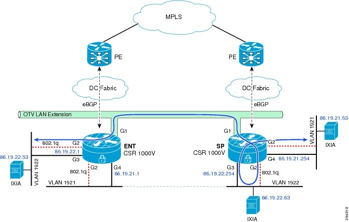
Inter-VLAN Flow with Gateway in Enterprise—These flows are routed flows over OTV. Two different traffic flow paths can exist depending on where the gateway is configured. If the gateway is Local CSR (Enterprise), then the packet will ingress on the L2 interface, egress on the routed L3 interface, ingress on the L2 interface and over OTV to the other data center and egress on the L2 interface. The traffic flow path will be as shown in Figure 5-4.
Figure 5-4 Inter-VLAN Flow with Gateway in Enterprise

The bridge table and mac entries for the given IP addressing in Figure 5-4 on two CSR would be as follows:
Enterprise CSR
ENT-t19-csr1#sh otv arp-nd-cache
Overlay19 ARP/ND L3->L2 Address Mapping Cache
BD MAC Layer-3 Address Age (HH:MM:SS) Local/Remote
1921 0000.0261.2437 86.19.21.64 00:00:59 Remote
ENT-t19-csr1#sh bridge-domain
Bridge-domain 936 (1 ports in all)
State: UP Mac learning: Enabled
Aging-Timer: 300 second(s)
GigabitEthernet2 service instance 936
MAC address Policy Tag Age Pseudoport
FFFF.FFFF.FFFF flood static 0 OLIST_PTR:0xe8e89400
Bridge-domain 1921 (2 ports in all)
State: UP Mac learning: Enabled
Aging-Timer: 1800 second(s)
GigabitEthernet2 service instance 1921
Overlay19 service instance 1921
MAC address Policy Tag Age Pseudoport
0050.5687.1FB2 forward dynamic_c 1800 GigabitEthernet2.EFP1921
0000.0261.2437 forward static_r 0 OCE_PTR:0xea2e8c00
FFFF.FFFF.FFFF flood static 0 OLIST_PTR:0xe8e89450
Bridge-domain 1922 (2 ports in all)
State: UP Mac learning: Enabled
Aging-Timer: 1800 second(s)
GigabitEthernet2 service instance 1922
Overlay19 service instance 1922
MAC address Policy Tag Age Pseudoport
FFFF.FFFF.FFFF flood static 0 OLIST_PTR:0xe8e89460
0000.0159.79B0 forward dynamic_c 1722 GigabitEthernet2.EFP1922
0050.5687.35F7 forward dynamic_c 1636 GigabitEthernet2.EFP1922
ENT-t19-csr1#sh ip arp
Protocol Address Age (min) Hardware Addr Type Interface
Internet 86.19.21.1 - 0050.5687.1fb2 ARPA GigabitEthernet7
Internet 86.19.21.64 1 0000.0261.2437 ARPA GigabitEthernet7
Internet 86.19.22.1 - 0050.5687.35f7 ARPA GigabitEthernet8
Internet 86.19.22.54 1 0000.0159.79b0 ARPA GigabitEthernet8
Internet 86.19.23.1 - 0050.5687.438b ARPA GigabitEthernet9
ENT-t19-csr1#sh otv route
Codes: BD - Bridge-Domain, AD - Admin-Distance,
SI - Service Instance, * - Backup Route
OTV Unicast MAC Routing Table for Overlay19
Inst VLAN BD MAC Address AD Owner Next Hops(s)
----------------------------------------------------------
0 1921 1921 0000.0261.2437 50 ISIS SP-t19-csr1
0 1921 1921 0050.5687.1fb2 40 BD Eng Gi2:SI1921
0 1922 1922 0000.0159.79b0 40 BD Eng Gi2:SI1922
0 1922 1922 0050.5687.35f7 40 BD Eng Gi2:SI1922
4 unicast routes displayed in Overlay19
----------------------------------------------------------
4 Total Unicast Routes Displayed
Service Provider CSR
SP-t19-csr1#sh otv arp-nd-cache
Overlay19 ARP/ND L3->L2 Address Mapping Cache
BD MAC Layer-3 Address Age (HH:MM:SS) Local/Remote
1921 0050.5687.1fb2 86.19.21.1 00:00:30 Remote
1922 0000.0159.79b0 86.19.22.54 00:00:33 Remote
SP-t19-csr1#sh bridge-dom
SP-t19-csr1#sh bridge-domain
Bridge-domain 936 (1 ports in all)
State: UP Mac learning: Enabled
Aging-Timer: 300 second(s)
GigabitEthernet2 service instance 936
MAC address Policy Tag Age Pseudoport
FFFF.FFFF.FFFF flood static 0 OLIST_PTR:0xe8f0f400
Bridge-domain 1921 (2 ports in all)
State: UP Mac learning: Enabled
Aging-Timer: 1800 second(s)
GigabitEthernet2 service instance 1921
Overlay19 service instance 1921
MAC address Policy Tag Age Pseudoport
0050.5687.1FB2 forward static_r 0 OCE_PTR:0xea36ec00
0000.0261.2437 forward dynamic_c 1756 GigabitEthernet2.EFP1921
FFFF.FFFF.FFFF flood static 0 OLIST_PTR:0xe8f0f450
Bridge-domain 1922 (2 ports in all)
State: UP Mac learning: Enabled
Aging-Timer: 1800 second(s)
GigabitEthernet2 service instance 1922
Overlay19 service instance 1922
MAC address Policy Tag Age Pseudoport
FFFF.FFFF.FFFF flood static 0 OLIST_PTR:0xe8f0f460
0000.0159.79B0 forward static_r 0 OCE_PTR:0xea36ec20
0050.5687.35F7 forward static_r 0 OCE_PTR:0xea36ec20
SP-t19-csr1# sh ip arp
Protocol Address Age (min) Hardware Addr Type Interface
Internet 86.19.21.254 - 0050.568f.6324 ARPA GigabitEthernet9
Internet 86.19.22.254 - 0050.568f.193c ARPA GigabitEthernet10
Internet 86.19.23.254 - 0050.568f.2b13 ARPA GigabitEthernet11
SP-t19-csr1#sh otv route
Codes: BD - Bridge-Domain, AD - Admin-Distance,
SI - Service Instance, * - Backup Route
OTV Unicast MAC Routing Table for Overlay19
Inst VLAN BD MAC Address AD Owner Next Hops(s)
----------------------------------------------------------
0 1921 1921 0000.0261.2437 40 BD Eng Gi2:SI1921
0 1921 1921 0050.5687.1fb2 50 ISIS ENT-t19-csr1
0 1922 1922 0000.0159.79b0 50 ISIS ENT-t19-csr1
0 1922 1922 0050.5687.35f7 50 ISIS ENT-t19-csr1
0 1923 1923 0050.5687.438b 50 ISIS ENT-t19-csr1
5 unicast routes displayed in Overlay19
----------------------------------------------------------
5 Total Unicast Routes Displayed
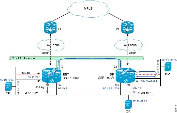
Inter-VLAN Flow with Gateway in Service Provider—The flow changes slightly if the gateway is on the remote CSR (Service Provider). In that case, the packet ingress on the L2 interface goes over OTV to the other data center, egresses on L2 interface on CSR, ingresses on L3 interface, and egresses on routed L3 interface. The traffic flow path will be as shown in Figure 5-5.
Figure 5-5 Inter-VLAN Flow with Gateway in Service Provider
The bridge table and mac entries for the given IP addressing in Figure 5-5 on two CSR would be as follows:
Enterprise CSR
ENT-t19-csr1#sh otv arp-nd-cache
Overlay19 ARP/ND L3->L2 Address Mapping Cache
BD MAC Layer-3 Address Age (HH:MM:SS) Local/Remote
1921 0000.0261.2435 86.19.21.63 00:01:07 Remote
1922 0050.568f.193c 86.19.22.254 00:01:04 Remote
ENT-t19-csr1#sh bridge-domain
Bridge-domain 936 (1 ports in all)
State: UP Mac learning: Enabled
Aging-Timer: 300 second(s)
GigabitEthernet2 service instance 936
MAC address Policy Tag Age Pseudoport
FFFF.FFFF.FFFF flood static 0 OLIST_PTR:0xe8f4d400
Bridge-domain 1921 (2 ports in all)
State: UP Mac learning: Enabled
Aging-Timer: 1800 second(s)
GigabitEthernet2 service instance 1921
Overlay19 service instance 1921
MAC address Policy Tag Age Pseudoport
0050.5687.1FB2 forward dynamic_c 1665 GigabitEthernet2.EFP1921
0000.0261.2435 forward static_r 0 OCE_PTR:0xea3acc00
FFFF.FFFF.FFFF flood static 0 OLIST_PTR:0xe8f4d450
Bridge-domain 1922 (2 ports in all)
State: UP Mac learning: Enabled
Aging-Timer: 1800 second(s)
GigabitEthernet2 service instance 1922
Overlay19 service instance 1922
MAC address Policy Tag Age Pseudoport
FFFF.FFFF.FFFF flood static 0 OLIST_PTR:0xe8f4d460
0000.0159.79AE forward dynamic_c 1800 GigabitEthernet2.EFP1922
0050.5687.35F7 forward dynamic_c 1668 GigabitEthernet2.EFP1922
0050.568F.193C forward static_r 0 OCE_PTR:0xea3acc20
ENT-t19-csr1#sh ip arp
Protocol Address Age (min) Hardware Addr Type Interface
Internet 86.19.21.1 - 0050.5687.1fb2 ARPA GigabitEthernet7
Internet 86.19.22.1 - 0050.5687.35f7 ARPA GigabitEthernet8
Internet 86.19.23.1 - 0050.5687.438b ARPA GigabitEthernet9
ENT-t19-csr1#sh otv route
Codes: BD - Bridge-Domain, AD - Admin-Distance,
SI - Service Instance, * - Backup Route
OTV Unicast MAC Routing Table for Overlay19
Inst VLAN BD MAC Address AD Owner Next Hops(s)
----------------------------------------------------------
0 1921 1921 0000.0261.2435 50 ISIS SP-t19-csr1
0 1921 1921 0050.5687.1fb2 40 BD Eng Gi2:SI1921
0 1922 1922 0000.0159.79ae 40 BD Eng Gi2:SI1922
0 1922 1922 0050.5687.35f7 40 BD Eng Gi2:SI1922
0 1922 1922 0050.568f.193c 50 ISIS SP-t19-csr1
5 unicast routes displayed in Overlay19
----------------------------------------------------------
5 Total Unicast Routes Displayed
Service Provider CSR
SP-t19-csr1#sh otv arp-nd-cache
Overlay19 ARP/ND L3->L2 Address Mapping Cache
BD MAC Layer-3 Address Age (HH:MM:SS) Local/Remote
1922 0000.0159.79ae 86.19.22.53 00:01:46 Remote
SP-t19-csr1#sh bridge-domain
Bridge-domain 936 (1 ports in all)
State: UP Mac learning: Enabled
Aging-Timer: 300 second(s)
GigabitEthernet2 service instance 936
MAC address Policy Tag Age Pseudoport
FFFF.FFFF.FFFF flood static 0 OLIST_PTR:0xe8e87000
Bridge-domain 1921 (2 ports in all)
State: UP Mac learning: Enabled
Aging-Timer: 1800 second(s)
GigabitEthernet2 service instance 1921
Overlay19 service instance 1921
MAC address Policy Tag Age Pseudoport
0050.5687.1FB2 forward static_r 0 OCE_PTR:0xea32c000
0000.0261.2435 forward dynamic_c 1681 GigabitEthernet2.EFP1921
FFFF.FFFF.FFFF flood static 0 OLIST_PTR:0xe8e87050
Bridge-domain 1922 (2 ports in all)
State: UP Mac learning: Enabled
Aging-Timer: 1800 second(s)
GigabitEthernet2 service instance 1922
Overlay19 service instance 1922
MAC address Policy Tag Age Pseudoport
FFFF.FFFF.FFFF flood static 0 OLIST_PTR:0xe8e87060
0000.0159.79AE forward static_r 0 OCE_PTR:0xea32c020
0050.5687.35F7 forward static_r 0 OCE_PTR:0xea32c020
0050.568F.193C forward dynamic_c 1683 GigabitEthernet2.EFP1922
SP-t19-csr1#sh ip arp
Protocol Address Age (min) Hardware Addr Type Interface
Internet 86.19.21.63 2 0000.0261.2435 ARPA GigabitEthernet9
Internet 86.19.21.254 - 0050.568f.6324 ARPA GigabitEthernet9
Internet 86.19.22.53 2 0000.0159.79ae ARPA GigabitEthernet10
Internet 86.19.22.254 - 0050.568f.193c ARPA GigabitEthernet10
Internet 86.19.23.254 - 0050.568f.2b13 ARPA GigabitEthernet11
SP-t19-csr1#sh otv route
Codes: BD - Bridge-Domain, AD - Admin-Distance,
SI - Service Instance, * - Backup Route
OTV Unicast MAC Routing Table for Overlay19
Inst VLAN BD MAC Address AD Owner Next Hops(s)
----------------------------------------------------------
0 1921 1921 0000.0261.2435 40 BD Eng Gi2:SI1921
0 1921 1921 0050.5687.1fb2 50 ISIS ENT-t19-csr1
0 1922 1922 0000.0159.79ae 50 ISIS ENT-t19-csr1
0 1922 1922 0050.5687.35f7 50 ISIS ENT-t19-csr1
0 1922 1922 0050.568f.193c 40 BD Eng Gi2:SI1922
5 unicast routes displayed in Overlay19
----------------------------------------------------------
5 Total Unicast Routes Displayed
ARP Suppression over OTV— CSR handles ARP over OTV differently. Instead of broadcasting all ARPs over OTV, an ARP suppression forwards only one ARP request per destination IP. In other words, if multiple host ARP for same gateway on remote site, it will forward only one ARP over OTV. It will then snoop the ARP reply and populates its ARP cache. The subsequent ARP request are suppressed at the Edge device and replied locally. The ARP request flow to remote end is as shown in Figure 5-6.
Figure 5-6 Flow with ARP Suppression
This is configured on OTV overlay interface using command otv suppress arp-nd.
ENT-t19-csr1#sh otv arp-nd-cache
Overlay19 ARP/ND L3->L2 Address Mapping Cache
BD MAC Layer-3 Address Age (HH:MM:SS) Local/Remote
1922 0000.0261.2435 86.19.22.63 00:01:07 Remote
1922 0050.568f.193c 86.19.22.254 00:01:04 Remote
Since flooding is not supported on UCS fabric interconnect, the MAC learning in compute happens with ARP only. To ensure the MAC entries do not time out in compute, it is recommended to configure ARP time-out lower than MAC age time-out. This can be configured on CSR L3 interfaces using command arp timeout <xx>.
IPsec over OTV—Packets traverse WAN over OTV. Tenant data traffic is secured by enabling IPsec encryption of any interesting traffic with source and destination IP address of OTV join interface. IPsec ACL is not classified based on host IP address as packets traverse with OTV header.
crypto map myvpn 10 ipsec-isakmp
set peer 86.68.32.62
set transform-set myset
match address 186
access-list 186 permit ip host 86.86.32.82 host 86.68.32.62

Note ![]() 86.86.32.82 and 86.68.32.62 are the IP addresses of CSR join interface.
86.86.32.82 and 86.68.32.62 are the IP addresses of CSR join interface.
Since CSR 1000v is software-based architecture, AES is the recommended IPsec encryption for the DRaaS System architecture. Triple DES encryption is supported on CSR, but was designed and developed to work better in hardware than software. 3DES encryption is CPU intensive and lowers throughput significantly.
AES Configuration
crypto ipsec transform-set myset esp-aes esp-md5-hmac
3DES Configuration
crypto ipsec transform-set myset esp-3des esp-md5-hmac
MAC Move across OTV—OTV supports VM mobility and is a critical feature for the DRaaS System architecture. OTV supports the move of servers from one data center to the other data center using IS-IS protocol. Generally, IS-IS advertises the MAC of the VM with a metric of one, but when the move happens, the new site learns the same MAC on a local port, and it then advertises the same MAC with the metric of zero. The new update updates the new route on all end devices in the OTV domain. Once the old end device stops advertising, the new end device advertises with metric of one instead of zero.
OTV Fragmentation—OTV fragmentation depends on the OTV path MTU. Since it has to account for OTV header and IPsec header, if encryption is enabled, the received packet size needs to be 1472 or 1372 bytes, respectively. See more details in the Best Practices/Caveats section. CSR can set DF bit in the IP header to 0, using the otv fragmentation join-interface <interface> command. By default, DF bit will be set to 1.
LISP Implementation
The Cisco LISP Virtual Machine Mobility (LISP VM-Mobility) solution allows any host to move anywhere in the network while preserving its IP address. The capability allows members of a subnet to be dispersed across many locations without requiring any changes on the hosts and while maintaining optimal routing and scalability in the network. LISP is a simple, incremental, network-based implementation that can be deployed on the CSR 1000V. It requires no changes to host stacks, DNS, or local network infrastructure, and little to no major changes to existing network infrastructures. In this section, we will look at how LISP could be deployed in a DRaaS System.
LISP Infrastructure Components
The LISP architecture defines seven new network infrastructure components. The components include an Ingress Tunnel Router (ITR), Egress Tunnel Router (ETR), Map Server, Map Resolver, ALT Router, Proxy Ingress Tunnel Router (PITR), and Proxy Ingress Egress Router (PETR). In some cases, a single physical device can implement more than one of these logical components.
xTR—ITR / ETR
The network design and performance requirements of the DRaaS System permit us to implement multiple logical LISP components onto a single CSR1000v. The CSR1000v can provide the ITR, ETR, Map Server, and Map Resolver LISP functions.
Configuring LISP xTR Router
The procedure below demonstrates how to configure the xTR router to support these LISP functions.
Step 1 ![]() Define the RLOC associated with the EID prefixes.
Define the RLOC associated with the EID prefixes.
hostname West-DC
!
router lisp
locator-set West-DC
11.1.5.1 priority 1 weight 100
Exit
Step 2 ![]() Create a dynamic EID policy to define which VLANs in the data center will support LISP VM Mobility. The database command defines the EID to RLOC mapping relationship, so when an EID is discovered the dynamic EID will be registered to the Map Server with the locator-set (RLOC) defined in Step 1. In this example, two VLANs support LISP VM Mobility.
Create a dynamic EID policy to define which VLANs in the data center will support LISP VM Mobility. The database command defines the EID to RLOC mapping relationship, so when an EID is discovered the dynamic EID will be registered to the Map Server with the locator-set (RLOC) defined in Step 1. In this example, two VLANs support LISP VM Mobility.
eid-table default instance-id 0
database-mapping 8.24.0.0/16 locator-set West-DC
dynamic-eid vlan2481
database-mapping 8.24.81.0/24 locator-set West-DC
exit
!
dynamic-eid vlan2482
database-mapping 8.24.82.0/24 locator-set West-DC
exit
!
Exit
Note ![]() All database-mapping dynamic-EID commands must be consistent on all LISP VM Mobility routers supporting the same roaming dynamic EID.
All database-mapping dynamic-EID commands must be consistent on all LISP VM Mobility routers supporting the same roaming dynamic EID.
Step 3 ![]() Use the following commands on the CSR 1000v to make the data center router an xTR, which will provide both ITR and ETR LISP functions.
Use the following commands on the CSR 1000v to make the data center router an xTR, which will provide both ITR and ETR LISP functions.
ipv4 itr
ipv4 etr
Step 4 ![]() Enable the Map Server and Map Resolver LISP functions on the xTR and configure the site details for LISP VM Mobility. Site attributes must be configured before an ETR can register with a Map Server. At a minimum, the EID prefixes to be registered by the ETR and a shared authentication key are required before an ETR is permitted to register EID prefixes with the Map Server. In this example, we use the accept-more-specifics attribute in the eid-prefix command to allow registration of any more specific eid-prefix that falls within the EID prefix 8.24.0.0/16.
Enable the Map Server and Map Resolver LISP functions on the xTR and configure the site details for LISP VM Mobility. Site attributes must be configured before an ETR can register with a Map Server. At a minimum, the EID prefixes to be registered by the ETR and a shared authentication key are required before an ETR is permitted to register EID prefixes with the Map Server. In this example, we use the accept-more-specifics attribute in the eid-prefix command to allow registration of any more specific eid-prefix that falls within the EID prefix 8.24.0.0/16.
site EastWestDC
authentication-key cisco
eid-prefix 8.24.0.0/16 accept-more-specifics
exit
!
ipv4 map-server
ipv4 map-resolver
Step 5 ![]() The xTR in each data center will perform Map Server (MS) and Map Resolver (MR) functions allowing for MS/MR redundancy. Configure the locations of each MS and MR.
The xTR in each data center will perform Map Server (MS) and Map Resolver (MR) functions allowing for MS/MR redundancy. Configure the locations of each MS and MR.
ipv4 itr map-resolver 11.1.5.1
ipv4 itr map-resolver 8.34.82.10
!
ipv4 etr map-server 11.1.5.1 key cisco
ipv4 etr map-server 8.34.82.10 key cisco
Step 6 ![]() Configure the location of the PxTR that we will use for routing LISP packets to non-LISP sites. When a packet arrives from inside the data center, the xTR performs a destination lookup in the routing table. If the lookup results in a match, the packet is forwarded natively. If there is no matching route in the routing table, the IP source of the packet will determine if the packet is dropped or LISP encapsulated. A packet whose source IP is a dynamic EID then packet is LISP encapsulated, if it is not the packet is dropped.
Configure the location of the PxTR that we will use for routing LISP packets to non-LISP sites. When a packet arrives from inside the data center, the xTR performs a destination lookup in the routing table. If the lookup results in a match, the packet is forwarded natively. If there is no matching route in the routing table, the IP source of the packet will determine if the packet is dropped or LISP encapsulated. A packet whose source IP is a dynamic EID then packet is LISP encapsulated, if it is not the packet is dropped.
ipv4 use-petr 6.126.104.130
Step 7 ![]() Enable LISP VM Mobility on the CSR 1000v server facing interfaces. The lisp mobility name must match one of the dynamic EID policies defined in Step 2. The lisp extended-subnet-mode command is used when a subnet is extended across a L3 cloud using an L2 extension technology such as OTV.
Enable LISP VM Mobility on the CSR 1000v server facing interfaces. The lisp mobility name must match one of the dynamic EID policies defined in Step 2. The lisp extended-subnet-mode command is used when a subnet is extended across a L3 cloud using an L2 extension technology such as OTV.
interface GigabitEthernet3
description VLAN 2481 Layer 3 Interface
ip address 8.24.81.2 255.255.255.0
standby 0 ip 8.24.81.1
lisp mobility vlan2481
lisp extended-subnet-mode
Step 8 ![]() Repeat the LISP VM Mobility configuration for the xTR router located in the East-DC.
Repeat the LISP VM Mobility configuration for the xTR router located in the East-DC.
hostname East-DC
!
router lisp
locator-set East-DC
8.34.82.10 priority 1 weight 100
exit
!
eid-table default instance-id 0
database-mapping 8.24.0.0/16 locator-set East-DC
dynamic-eid vlan2481
database-mapping 8.24.81.0/24 locator-set East-DC
exit
!
dynamic-eid vlan2482
database-mapping 8.24.82.0/24 locator-set East-DC
exit
!
exit
!
site EastWestDC
authentication-key cisco
eid-prefix 8.24.0.0/16 accept-more-specifics
exit
!
ipv4 map-server
ipv4 map-resolver
ipv4 map-request-source 8.34.82.10
ipv4 use-petr 6.126.104.130
ipv4 itr map-resolver 11.1.5.1
ipv4 itr map-resolver 8.34.82.10
ipv4 itr
ipv4 etr map-server 11.1.5.1 key cisco
ipv4 etr map-server 8.34.82.10 key cisco
ipv4 etr
!
interface GigabitEthernet3
description VLAN 2481 Layer 3 Interface
ip address 8.24.81.3 255.255.255.0
standby 0 ip 8.24.81.1
lisp mobility vlan2481
lisp extended-subnet-mode
PxTR—PITR / PETR
The LISP proxy router (PxTR) can reside in the enterprise and provide both PITR and PETR functions. The map-cache command is used to force the PxTR to send a map-request for a map-cache miss when the packet destination matches the coarse-aggregate EID prefix 8.24.0.0/16.
router lisp
eid-table default instance-id 0
map-cache 8.24.0.0/16 map-request
exit
!
ipv4 map-request-source 6.126.104.130
ipv4 map-cache-limit 100000
ipv4 proxy-etr
ipv4 proxy-itr 6.126.104.130
ipv4 itr map-resolver 11.1.5.3
General Routing Policy
The forwarding rules for LISP determine how a packet is forwarded by an xTR. The xTR does a destination lookup in the routing table, if the route is found the packet is forwarded natively. If the route is not found, the packet is either LISP encapsulated or dropped depending on if the packet is sourced from an EID. If a packet whose source IP is a dynamic EID, then the packet is LISP encapsulated, if it is not the packet is dropped.
Note ![]() EID prefixes should never be injected into the routing table and advertised to the PE via BGP.
EID prefixes should never be injected into the routing table and advertised to the PE via BGP.
Figure 5-7 General Routing Policy when using LISP
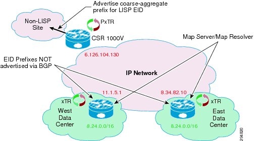
The PxTR functions as both PITR and PETR, and provides LISP to non-LISP inter-networking. The PITR attracts non-LISP packets by advertising a coarse-aggregate prefix for LISP EIDs into the non-LISP domain, and then performs LISP encapsulation to provide access to LISP EIDs. The PETR receives LISP-encapsulated packets from LISP sites, removes the encapsulation and forwards them into the non-LISP domain.
Firewall Policy
The CSR1000V provides firewall services through the use of zoned-based firewall. The DRaaS System implements a three-zone implementation:
•![]() The inside zone applies to any server-facing interface and will provide a security policy for inter-VLAN native IP traffic that is confined to the data center.
The inside zone applies to any server-facing interface and will provide a security policy for inter-VLAN native IP traffic that is confined to the data center.
•![]() The outside zone applies to the northbound interface and will provide a security policy for northbound native IP traffic.
The outside zone applies to the northbound interface and will provide a security policy for northbound native IP traffic.
•![]() The LISP0 interface is where LISP encapsulation and decapsulation occurs. The LISP zone is applied to the logical LISP0 interface which defines the security policy for LISP encapsulated packets. Two traffic flows need to be considered when applying a zone-based firewall for LISP encapsulated packets:
The LISP0 interface is where LISP encapsulation and decapsulation occurs. The LISP zone is applied to the logical LISP0 interface which defines the security policy for LISP encapsulated packets. Two traffic flows need to be considered when applying a zone-based firewall for LISP encapsulated packets:
–![]() LISP-to-NON-LISP traffic flows to/from the PxTR, and LISP to LISP traffic flows to/from a remote LISP site.
LISP-to-NON-LISP traffic flows to/from the PxTR, and LISP to LISP traffic flows to/from a remote LISP site.
–![]() LISP-to-LISP inter-VLAN traffics flows between EIDs located in different data centers.
LISP-to-LISP inter-VLAN traffics flows between EIDs located in different data centers.
Figure 5-8 CSR1000V Configured Zones
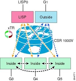
The zone-pair is used to define the security policy between zones. The example below demonstrates how an inter-zone security policy might be applied to support the requirements shown in Figure 5-8. First, create the zones and define the security policies between zones.
zone security outside
zone security inside
zone security lisp
zone-pair security inside-to-inside source inside destination inside
service-policy type inspect inside-to-inside
zone-pair security inside-to-lisp source inside destination lisp
service-policy type inspect inside-to-lisp
zone-pair security inside-to-outside source inside destination outside
service-policy type inspect inside-to-outside
zone-pair security lisp-to-inside source lisp destination inside
service-policy type inspect lisp-to-inside
zone-pair security outside-to-inside source outside destination inside
service-policy type inspect outside-to-inside
The appropriate security zone is then applied to the physical interface. The security zone for LISP traffic is applied to the virtual interface LISP0. The virtual interface is where LISP encapsulation and decapsulation occurs, allowing the firewall to inspect egress packets before LISP encapsulation and ingress packets after LISP decapsulation. With the virtual interface we can now have different security policies for LISP and native IP traffic applied to a single physical interface.
int lisp0
description LISP Encap/Decap
zone-member security lisp
interface GigabitEthernet1
description Uplink to DC Fabric
zone-member security outside
interface GigabitEthernet3
description L3 Interface VLAN 2481 - LISP Dynamic EID
zone-member security inside
interface GigabitEthernet4
description L3 Interface VLAN 2482 - LISP Dynamic EID
zone-member security inside
interface GigabitEthernet5
description L3 Interface VLAN 2483 - LISP Dynamic EID
zone-member security inside
LISP Control Plane
LISP control plane packets are UDP-based messages. The IANA registry has allocated UDP port numbers 4341 LISP data packets and 4342 for LISP control packets. The LISP control message packet format is shown in Figure 5-9. The five LISP control plane message types are currently:
•![]() Map-Request
Map-Request
•![]() Map-Reply
Map-Reply
•![]() Map-Register
Map-Register
•![]() Map-Notify
Map-Notify
•![]() Encapsulated Control Message
Encapsulated Control Message
Figure 5-9 LISP Control Plane Packet Format

Map-Request
This message is sent by an ITR to the mapping database when it needs to send a packet to a destination EID for which is has no cached RLOC.
Map-Reply
This message is returned to an ITR by an ETR or map server in response to a Map-Request message. A Map-Reply message contains the EID prefix that matches the requested destination EID along with a set of RLOCs that can be used as the destination IP addresses for encapsulating user data.
Map-Register
This message is sent by an ETR to a map server to specify an EID prefix that it owns as well as the RLOCs that should be used for exchanging Map-Request and Map-Reply messages. Registration request includes the EID prefix, prefix length, RLOCs associated with the prefix, and priorities and traffic sharing weights of each RLOC. Map-Register messages are sent periodically to maintain the registration state between an ETR and its map servers.
Map-Notify
A LISP message sent by a Map-Server to an ETR to confirm that a Map-Register has been received and processed. The Map-Notify message uses UDP port number 4342 for both source and destination.
Encapsulated Control Message
This message is a Map-Request message that is encapsulated within an Encapsulated Control Message. It is sent from an ITR to a Map-Resolver and by a Map-Server when forwarding a Map-Request to an ETR.
The RLOC or Record Locator is the IP address of the ETR. The RLOC is the output of an EID to RLOC mapping lookup on the ITR. The resulting lookup produces an EID mapping to one or more RLOCs. When a packet arrives at an ITR, a route lookup occurs and a forwarding decision is made. If the route is found or a default route exists, the packet is forwarded natively. Otherwise, the packet is either LISP encapsulated or dropped. When a packet meets the criteria for LISP forwarding, the steps to locate the EID to RLOC binding or mapping is shown in Figure 5-10.
Figure 5-10 LISP Control Plane during a LISP VM Mobility Event
The following steps are required for an ITR to retrieve valid mapping information from the mapping database:
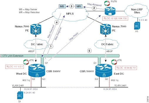
1. ![]() The ETRs first register their EID prefixes with the Map-Server. In this instance, West-DC would register both 8.24.81.0/24 and 8.24.81.40/32 EID prefixes, while East-DC would only register EID prefix 8.24.81.0/24. Each ETR will send Map-Registration messages every 60 seconds.
The ETRs first register their EID prefixes with the Map-Server. In this instance, West-DC would register both 8.24.81.0/24 and 8.24.81.40/32 EID prefixes, while East-DC would only register EID prefix 8.24.81.0/24. Each ETR will send Map-Registration messages every 60 seconds.
2. ![]() H1 sends a packet to S1, and no entry for S1 exists in the local map-cache of the PXTR. The PITR sends a Map-Request message to the Map-Resolver.
H1 sends a packet to S1, and no entry for S1 exists in the local map-cache of the PXTR. The PITR sends a Map-Request message to the Map-Resolver.
3. ![]() The Map-Resolver forwards the Map-Request message to the Map-Server.
The Map-Resolver forwards the Map-Request message to the Map-Server.
4. ![]() The Map-Server forwards the Map-Request to the ETR that last registered the EID prefix.
The Map-Server forwards the Map-Request to the ETR that last registered the EID prefix.
5. ![]() The ETR sends a Map-Reply to the PITR containing the requested mapping information.
The ETR sends a Map-Reply to the PITR containing the requested mapping information.
Note ![]() In the DRaaS System, the Map-Resolver and Map-Server function can both be installed on the LISP data center router for redundancy. In addition, both Map-Resolver and Map-Server functions can be enabled on each data center LISP router.
In the DRaaS System, the Map-Resolver and Map-Server function can both be installed on the LISP data center router for redundancy. In addition, both Map-Resolver and Map-Server functions can be enabled on each data center LISP router.
LISP VM Mobility
LISP VM Mobility supports both Across Subnet Mode (ASM) and Extended Subnet Mode (ESM). For the DRaaS use case, LISP VM Mobility using ESM is required to enable support for partial failover. This would enable servers that send non-routable heartbeat messages to operate during a partial failover.
LISP VM Mobility ESM Prerequisites
Enabling LISP VM Mobility with an extended subnet has some prerequisites.
The default gateway (FHR) for each server VLAN should use the same IP and MAC in both data centers. This can be accomplished by enabling HSRP on the CSR 1000V server-facing L3 interfaces. It's important to maintain FHRP isolation when using OTV. HSRP routers should never peer with other HSRP routers over OTV. The CSR 1000v OTV implementation by default filters FHRP control packets on the Overlay interface, which prevents HSRP peering across OTV (Figure 5-11).
Figure 5-11 OTV and First Hop Redundancy Protocol (FHRP) Isolation
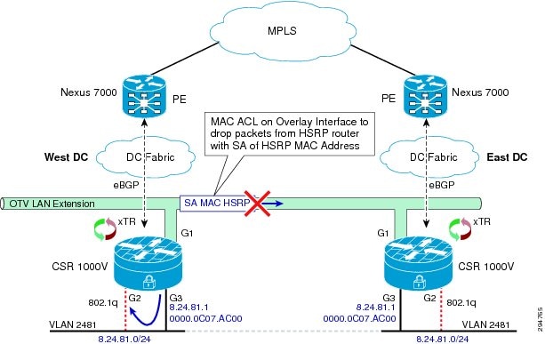
In addition to HSRP hello packets, which are dropped by default, control packets like ARP and Gratuitous ARP that are sourced from the HSRP MAC address must also be isolated to the data center. An L2 MAC ACL should be used on the Overlay interface to prevent these packets from being forwarded across OTV. The ACL shown below prevents any packet with a source MAC address of the HSRP MAC address to any destination MAC address from being sent over OTV. Apply the L2 MAC ACL to each EFP instance under the Overlay interface.
mac access-list extended drop-hsrp-mac
deny 0000.0c07.ac00 0000.0000.00ff host 0000.0000.0000
permit host 0000.0000.0000 host 0000.0000.0000
!
interface Overlay1
mtu 1350
no ip address
otv join-interface GigabitEthernet1
otv use-adjacency-server 8.34.82.10 unicast-only
service instance 2481 ethernet
encapsulation dot1q 2481
mac access-group drop-hsrp-mac out
bridge-domain 2481
!
service instance 2482 ethernet
encapsulation dot1q 2482
mac access-group drop-hsrp-mac out
bridge-domain 2482
LISP Dynamic EID Detection
A DRaaS recovery operation results in a VM or dynamic EID move across data centers. The xTR in the target data center must first detect that the VM has moved. In the Cisco IOS-XE 3.10S release, the mechanism for dynamic EID detection is data plane only. Control plane dynamic EID detection may be supported in a future release.
A dynamic EID move is detected when the xTR receives a unicast IP packet from the VM. The xTR registers the dynamic EID with the Map-Server causing LISP to direct traffic to the VMs new location. LISP control plane debugs can be used to show when a dynamic EID has been detected. The debug output below shows two instances where a dynamic EID is detected. The first PD detect is a multicast packet that is ignored by the xTR, and the second packet results in dynamic EID being detected.
Nov  9 02:48:31.021: LISPdyn-EID: PD detected IPv4:Default:86.21.21.40 on
GigabitEthernet3
Nov  9 02:48:31.021: LISPdyn-EID: Ignoring detection from multicast packet
IPv4:Default:86.21.21.40 to 224.0.0.252 on GigabitEthernet3
Nov  9 02:48:34.944: LISPdyn-EID: PD detected IPv4:Default:86.21.21.40 on
GigabitEthernet3
In a Windows environment where NetBIOS over IP is enabled on servers residing in the data center, an inbound L3 ACL should be applied to the CSR server-facing L3 interfaces to drop NetBIOS over IP packets. Adding an L3 ACL to drop NetBIOS over IP packets will help speed up the time it takes LISP to converge after a VM mobility event.
A DRaaS recovery is effectively a VM Mobility event, where the target VM is powered up in the remote data center. The LISP router in the remote DC must first detect that the VM has moved. If the VM is running Windows OS with NetBIOS over IP enabled, the VM will send multiple NetBIOS over IP packets on the wire during the boot up process. These packets are sent to the subnet broadcast address, see packet format below, which will be forwarded to both the local DC LISP router and the remote DC LISP router via OTV. NetBIOS over IP packets will trigger a dynamic EID detection, so each time the VM sends out a NetBIOS over IP packet the dynamic EID is detected by LISP routers in both DCs. This constant relearning of the dynamic EID between local and remote data centers will cause packet loss until the Windows PC stops sending NetBIOS over IP packets.
NetBIOS over IP Packet Format
Frame 17: 110 bytes on wire (880 bits), 110 bytes captured (880 bits)
Ethernet II, Src: Olicom_81:00:40 (00:00:24:81:00:40), Dst: Broadcast
(ff:ff:ff:ff:ff:ff)
Internet Protocol Version 4, Src: 8.24.81.40 (8.24.81.40), Dst: 8.24.81.255
(8.24.81.255)
User Datagram Protocol, Src Port: netbios-ns (137), Dst Port: netbios-ns (137)
Source port: netbios-ns (137)
Destination port: netbios-ns (137)
Length: 76
Checksum: 0xb3b4 [validation disabled]
NetBIOS Name Service
Transaction ID: 0xedfe
Flags: 0x2910 (Registration)
Questions: 1
Answer RRs: 0
Authority RRs: 0
Additional RRs: 1
Queries
Additional records
One can avoid this problem in different ways. One method is to disable NetBIOS over IP on all Windows PCs in the data center. Figure 5-12 shows how to configure NetBIOS over IP.
Figure 5-12 Configure Windows PC NetBIOS Settings
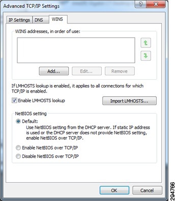
An easier approach is to apply an inbound L3 ACL that drops NetBIOS over IP packets on the CSR 1000V server-facing L3 interfaces. The sample configuration below shows how to drop NetBIOS over IP packets using a L3 ACL on all CSR 1000V server-facing L3 interfaces.
interface GigabitEthernet3
description VLAN 2481 Layer 3 Interface
ip address 8.24.81.2 255.255.255.0
ip access-group 2000 in
standby 0 ip 8.24.81.1
lisp mobility vlan2481
lisp extended-subnet-mode
!
access-list 2000 deny udp any eq netbios-ns any eq netbios-ns
access-list 2000 deny udp any eq netbios-ss any eq netbios-ss
access-list 2000 deny udp any eq netbios-dgm any eq netbios-dgm
access-list 2000 permit ip any any
LISP Mobility Events
In a DRaaS recovery operation, a protected VM located in the primary data center is recovered to a target VM in the secondary data center. LISP VM Mobility is ideal for this use case. The following examples show how different traffic flows are affected by a LISP mobility event. The three traffic flows covered in this section are:
•![]() NON-LISP to EID Traffic Flow after a Mobility Event
NON-LISP to EID Traffic Flow after a Mobility Event
•![]() EID to EID Intra-VLAN Traffic Flow after a Mobility Event
EID to EID Intra-VLAN Traffic Flow after a Mobility Event
•![]() EID to EID Inter-VLAN Traffic Flow after a Mobility Event
EID to EID Inter-VLAN Traffic Flow after a Mobility Event
Note ![]() The Map Server and Map Resolver functions were offloaded to a separate device in these examples to help describe the LISP control plane. In a real deployment the MS/MR function would be installed on the xTR in each data center.
The Map Server and Map Resolver functions were offloaded to a separate device in these examples to help describe the LISP control plane. In a real deployment the MS/MR function would be installed on the xTR in each data center.
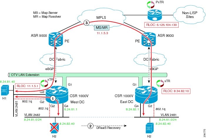
NON-LISP to EID Traffic Flow after a Mobility Event
Figure 5-13 describes communication to the EID from NON-LISP sites.
1. ![]() The original traffic flow from the PxTR to the DC is through the xTR in the West-DC.
The original traffic flow from the PxTR to the DC is through the xTR in the West-DC.
2. ![]() User performs a DRaaS recovery operation resulting in the VM being moved to the East-DC.
User performs a DRaaS recovery operation resulting in the VM being moved to the East-DC.
3. ![]() Temporary sub-optimal routing through the xTR in the West-DC will occur before LISP converges.
Temporary sub-optimal routing through the xTR in the West-DC will occur before LISP converges.
4. ![]() LISP detects the VM move and routes NON-LISP to EID traffic from the PxTR to the xTR in the East-DC.
LISP detects the VM move and routes NON-LISP to EID traffic from the PxTR to the xTR in the East-DC.
Figure 5-13 Non-LISP to EID Traffic Flow

The state of each LISP components prior to performing the DRaaS recovery operation is shown below. The Map Server shows xTR in the West-DC has registered the EID prefix 8.24.81.40/32 with the Map Server.
MS-MR#show lisp site
LISP Site Registration Information
Site Name Last Up Who Last Inst EID Prefix
Register Registered ID
EastWestDC 00:00:46 yes 11.1.5.1 8.24.0.0/16
00:00:46 yes 11.1.5.1 8.24.81.40/32
The PxTR local map-cache shows the current RLOC for the EID Prefix 8.24.81.40/32 is the West-DC xTR whose RLOC is 11.1.5.1. Traffic from H1 destined to H2 enters the data center through the xTR in the West-DC.
pxtr#show ip lisp map-cache
LISP IPv4 Mapping Cache for EID-table default (IID 0), 2 entries
8.24.0.0/16, uptime: 2d17h, expires: never, via static send map-request
Negative cache entry, action: send-map-request
8.24.81.40/32, uptime: 00:03:13, expires: 23:56:46, via map-reply, complete
Locator Uptime State Pri/Wgt
11.1.5.1 00:03:13 up 1/100
The xTRs in both East and West-DCs show that H2 resides in the West-DC and traffic to H2 from H1 will enter through the xTR in the West-DC.
West-DC#show ip lisp database
LISP ETR IPv4 Mapping Database for EID-table default (IID 0), LSBs: 0x1, 2 entries
8.24.0.0/16, locator-set West-DC
Locator Pri/Wgt Source State
11.1.5.1 1/100 cfg-addr site-self, reachable
8.24.81.40/32, dynamic-eid vlan2481, locator-set West-DC
Locator Pri/Wgt Source State
11.1.5.1 1/100 cfg-addr site-self, reachable
East-DC#show ip lisp database
LISP ETR IPv4 Mapping Database for EID-table default (IID 0), LSBs: 0x1, 1 entries
8.24.0.0/16, locator-set East-DC
Locator Pri/Wgt Source State
8.34.82.10 1/100 cfg-addr site-self, reachable
Figure 5-14 LISP Control Plane during a VM Mobility Event
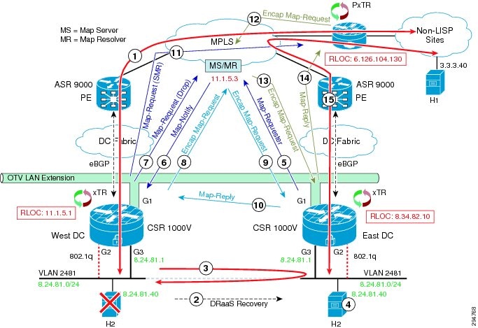
The following control plane packet flows occur after a VM Mobility event.
1. ![]() The traffic from H1 to H2 enters the virtual data center through the xTR in the West-DC.
The traffic from H1 to H2 enters the virtual data center through the xTR in the West-DC.
2. ![]() A DRaaS recovery operation is performed on H2 causing H2 to move to the East-DC.
A DRaaS recovery operation is performed on H2 causing H2 to move to the East-DC.
3. ![]() A small number of packets are received form H1 at the xTR in the West-DC. These packets will trombone across OTV until LISP converges. In our topology, only one data packet was sent across OTV.
A small number of packets are received form H1 at the xTR in the West-DC. These packets will trombone across OTV until LISP converges. In our topology, only one data packet was sent across OTV.
4. ![]() The xTR in the East-DC detects that H2 has moved.
The xTR in the East-DC detects that H2 has moved.
5. ![]() Once a dynamic EID event is detected, the xTR in the East-DC sends a Map-Register message to Map Server for EID prefix 8.24.81.40/32 with a new status of Reachable.
Once a dynamic EID event is detected, the xTR in the East-DC sends a Map-Register message to Map Server for EID prefix 8.24.81.40/32 with a new status of Reachable.
Frame 106: 130 bytes on wire (1040 bits), 130 bytes captured (1040 bits)
Ethernet II, Src: Vmware_8f:65:7e (00:50:56:8f:65:7e), Dst: Cisco_9f:fd:9a
Internet Protocol Version 4, Src: 8.34.82.10 (8.34.82.10), Dst: 11.1.5.3
(11.1.5.3)
User Datagram Protocol, Src Port: lisp-control (4342), Dst Port: lisp-control
(4342)
Locator/ID Separation Protocol
0011 .... .... .... .... .... = Type: Map-Register (3)
.... 0... .... .... .... .... = P bit (Proxy-Map-Reply): Not set
.... .010 0000 0000 0000 000. = Reserved bits: 0x010000
.... .... .... .... .... ...1 = M bit (Want-Map-Notify): Set
Record Count: 1
Nonce: 0x2bd3b44885169623
Key ID: 0x0001
Authentication Data Length: 20
Authentication Data: 74f764febdfcde820127ffa96d11e7082a5a5a21
EID prefix: 8.24.81.40/32, TTL: 1440, Authoritative, No-Action
0000 .... .... .... = Reserved: 0x0000
.... 0000 0000 0000 = Mapping Version: 0
    Local RLOC: 8.34.82.10, Reachable, Priority/Weight: 1/100, Mcast
Priority/Weight: 255/0
Data (24 bytes)
6. ![]() The xTR in the West-DC receives a Map-Notify message from the Map Server for EID prefix 8.24.81.40/32. The information in the message specifies the new RLOC for this prefix as the xTR in the East-DC (8.34.82.10). The xTR in West-DC now knows that H2 has moved.
The xTR in the West-DC receives a Map-Notify message from the Map Server for EID prefix 8.24.81.40/32. The information in the message specifies the new RLOC for this prefix as the xTR in the East-DC (8.34.82.10). The xTR in West-DC now knows that H2 has moved.
Frame 101: 130 bytes on wire (1040 bits), 130 bytes captured (1040 bits)
Ethernet II, Src: Vmware_8c:34:83 (00:50:56:8c:34:83), Dst: Vmware_8c:03:27
Internet Protocol Version 4, Src: 11.1.5.3 (11.1.5.3), Dst: 11.1.5.1 (11.1.5.1)
User Datagram Protocol, Src Port: lisp-control (4342), Dst Port: lisp-control
(4342)
Locator/ID Separation Protocol
0100 .... .... .... .... .... = Type: Map-Notify (4)
.... 1000 0000 0000 0000 0000 = Reserved bits: 0x080000
Record Count: 1
Nonce: 0x9b3acb6883ca9060
Key ID: 0x0001
Authentication Data Length: 20
Authentication Data: 0a0bbb6378fe8a8bf7a72aec107751b9e039d021
EID prefix: 8.24.81.40/32, TTL: 1440, Not Authoritative, No-Action
0000 .... .... .... = Reserved: 0x0000
.... 0000 0000 0000 = Mapping Version: 0
        RLOC: 8.34.82.10, Reachable, Priority/Weight: 1/100, Multicast
Priority/Weight: 255/0
Data (24 bytes)
7. ![]() The xTR in the West-DC sends a Map-Register message for EID prefix 8.24.81.40/32 to the Map Server with the status set to Drop.
The xTR in the West-DC sends a Map-Register message for EID prefix 8.24.81.40/32 to the Map Server with the status set to Drop.
Frame 102: 118 bytes on wire (944 bits), 118 bytes captured (944 bits)
Ethernet II, Src: Vmware_8c:03:27 (00:50:56:8c:03:27), Dst: Vmware_8c:34:83
(00:50:56:8c:34:83)
Internet Protocol Version 4, Src: 11.1.5.1 (11.1.5.1), Dst: 11.1.5.3 (11.1.5.3)
User Datagram Protocol, Src Port: lisp-control (4342), Dst Port: lisp-control
(4342)
Locator/ID Separation Protocol
0011 .... .... .... .... .... = Type: Map-Register (3)
.... 0... .... .... .... .... = P bit (Proxy-Map-Reply): Not set
.... .010 0000 0000 0000 000. = Reserved bits: 0x010000
.... .... .... .... .... ...1 = M bit (Want-Map-Notify): Set
Record Count: 1
Nonce: 0xa7cbb5b0fc7a656d
Key ID: 0x0001
Authentication Data Length: 20
Authentication Data: 29ff66e37996b5389e154c463cddff4b8323b782
EID prefix: 8.24.81.40/32, TTL: 0, Authoritative, Drop
0000 .... .... .... = Reserved: 0x0000
.... 0000 0000 0000 = Mapping Version: 0
Data (24 bytes)
8. ![]() The xTR in the West-DC sends an Encapsulated Map-Request for 8.24.81.40/32 to the Map Resolver.
The xTR in the West-DC sends an Encapsulated Map-Request for 8.24.81.40/32 to the Map Resolver.
Frame 109: 106 bytes on wire (848 bits), 106 bytes captured (848 bits)
Ethernet II, Src: Vmware_8c:03:27 (00:50:56:8c:03:27), Dst: Vmware_8c:34:83
(00:50:56:8c:34:83)
Internet Protocol Version 4, Src: 11.1.5.1 (11.1.5.1), Dst: 11.1.5.3 (11.1.5.3)
User Datagram Protocol, Src Port: lisp-control (4342), Dst Port: lisp-control
(4342)
Locator/ID Separation Protocol
Internet Protocol Version 4, Src: 11.1.5.1 (11.1.5.1), Dst: 8.24.81.40
(8.24.81.40)
User Datagram Protocol, Src Port: lisp-control (4342), Dst Port: lisp-control
(4342)
Locator/ID Separation Protocol
0001 .... .... .... .... .... = Type: Map-Request (1)
.... 0... .... .... .... .... = A bit (Authoritative): Not set
.... .0.. .... .... .... .... = M bit (Map-Reply present): Not set
.... ..0. .... .... .... .... = P bit (Probe): Not set
.... ...0 .... .... .... .... = S bit (Solicit-Map-Request): Not set
.... .... 0... .... .... .... = p bit (Proxy ITR): Not set
.... .... .0.. .... .... .... = s bit (SMR-invoked): Not set
.... .... ..00 0000 000. .... = Reserved bits: 0x000000
.... .... .... .... ...0 0000 = ITR-RLOC Count: 0
Record Count: 1
Nonce: 0x01924e32da36ff28
Source EID AFI: 1
Source EID: 3.3.3.40 (3.3.3.40)
ITR-RLOC 1: 11.1.5.1
ITR-RLOC-AFI: 1
ITR-RLOC Address: 11.1.5.1 (11.1.5.1)
Record 1: 8.24.81.40/32
Reserved bits: 0x00
Prefix length: 32
Prefix AFI: 1
Prefix: 8.24.81.40
9. ![]() The Map Server forwards the Encapsulated Map-Request for 8.24.81.40/32 from Step 8 to the xTR in the East-DC. Notice that only the outer LISP header IP source and destination addresses have changed. The new source IP is the Map Server and the destination is the target xTR.
The Map Server forwards the Encapsulated Map-Request for 8.24.81.40/32 from Step 8 to the xTR in the East-DC. Notice that only the outer LISP header IP source and destination addresses have changed. The new source IP is the Map Server and the destination is the target xTR.
Frame 112: 106 bytes on wire (848 bits), 106 bytes captured (848 bits)
Ethernet II, Src: Cisco_79:0f:41 (00:22:55:79:0f:41), Dst: Vmware_8f:65:7e
(00:50:56:8f:65:7e)
Internet Protocol Version 4, Src: 11.1.5.3 (11.1.5.3), Dst: 8.34.82.10
(8.34.82.10)
User Datagram Protocol, Src Port: lisp-control (4342), Dst Port: lisp-control
(4342)
Locator/ID Separation Protocol
1000 .... .... .... .... .... = Type: Encapsulated Control Message (8)
.... 0000 0000 0000 0000 0000 0000 0000 = Reserved bits: 0x00000000
Internet Protocol Version 4, Src: 11.1.5.1 (11.1.5.1), Dst: 8.24.81.40
(8.24.81.40)
User Datagram Protocol, Src Port: lisp-control (4342), Dst Port: lisp-control
(4342)
Locator/ID Separation Protocol
0001 .... .... .... .... .... = Type: Map-Request (1)
.... 0... .... .... .... .... = A bit (Authoritative): Not set
.... .0.. .... .... .... .... = M bit (Map-Reply present): Not set
.... ..0. .... .... .... .... = P bit (Probe): Not set
.... ...0 .... .... .... .... = S bit (Solicit-Map-Request): Not set
.... .... 0... .... .... .... = p bit (Proxy ITR): Not set
.... .... .0.. .... .... .... = s bit (SMR-invoked): Not set
.... .... ..00 0000 000. .... = Reserved bits: 0x000000
.... .... .... .... ...0 0000 = ITR-RLOC Count: 0
Record Count: 1
Nonce: 0x01924e32da36ff28
Source EID AFI: 1
Source EID: 3.3.3.40 (3.3.3.40)
ITR-RLOC 1: 11.1.5.1
ITR-RLOC-AFI: 1
ITR-RLOC Address: 11.1.5.1 (11.1.5.1)
Record 1: 8.24.81.40/32
Reserved bits: 0x00
Prefix length: 32
Prefix AFI: 1
Prefix: 8.24.81.40
10. ![]() The xTR in the East-DC sends a Map-Reply message to the West-DC xTR for the EID prefix 8.24.81.40/32.
The xTR in the East-DC sends a Map-Reply message to the West-DC xTR for the EID prefix 8.24.81.40/32.
11. ![]() The xTR in the West-DC sends a Map-Request message to the PxTR with the Solicit-Map-Request (SMR) bit set.
The xTR in the West-DC sends a Map-Request message to the PxTR with the Solicit-Map-Request (SMR) bit set.
Frame 110: 74 bytes on wire (592 bits), 74 bytes captured (592 bits)
Ethernet II, Src: Vmware_8c:03:27 (00:50:56:8c:03:27), Dst: 84:78:ac:6b:98:63
(84:78:ac:6b:98:63)
Internet Protocol Version 4, Src: 11.1.5.1 (11.1.5.1), Dst: 6.126.104.130
(6.126.104.130)
User Datagram Protocol, Src Port: lisp-control (4342), Dst Port: lisp-control
(4342)
Locator/ID Separation Protocol
0001 .... .... .... .... .... = Type: Map-Request (1)
.... 0... .... .... .... .... = A bit (Authoritative): Not set
.... .0.. .... .... .... .... = M bit (Map-Reply present): Not set
.... ..1. .... .... .... .... = P bit (Probe): Set
.... ...1 .... .... .... .... = S bit (Solicit-Map-Request): Set
.... .... 0... .... .... .... = p bit (Proxy ITR): Not set
.... .... .0.. .... .... .... = s bit (SMR-invoked): Not set
.... .... ..00 0000 001. .... = Reserved bits: 0x000001
.... .... .... .... ...0 0000 = ITR-RLOC Count: 0
Record Count: 1
Nonce: 0xde45c1c4ff5549c4
Source EID AFI: 1
Source EID: 8.24.81.40 (8.24.81.40)
ITR-RLOC 1: 11.1.5.1
ITR-RLOC-AFI: 1
ITR-RLOC Address: 11.1.5.1 (11.1.5.1)
Record 1: 3.3.3.40/32
Reserved bits: 0x00
Prefix length: 32
Prefix AFI: 1
Prefix: 3.3.3.40
12. ![]() The PxTR sends an Encapsulated Map-Request message to the Map Resolver for 8.24.84.40/32.
The PxTR sends an Encapsulated Map-Request message to the Map Resolver for 8.24.84.40/32.
Frame 102: 106 bytes on wire (848 bits), 106 bytes captured (848 bits)
Ethernet II, Src: Vmware_a6:c4:ec (00:50:56:a6:c4:ec), Dst: Cisco_9f:f9:98
(00:00:0c:9f:f9:98)
Internet Protocol Version 4, Src: 6.126.104.130 (6.126.104.130), Dst: 11.1.5.3
(11.1.5.3)
User Datagram Protocol, Src Port: lisp-control (4342), Dst Port: lisp-control
(4342)
Locator/ID Separation Protocol
1000 .... .... .... .... .... = Type: Encapsulated Control Message (8)
.... 0000 0000 0000 0000 0000 0000 0000 = Reserved bits: 0x00000000
Internet Protocol Version 4, Src: 6.126.104.130 (6.126.104.130), Dst: 8.24.81.40
(8.24.81.40)
User Datagram Protocol, Src Port: lisp-control (4342), Dst Port: lisp-control
(4342)
Locator/ID Separation Protocol
0001 .... .... .... .... .... = Type: Map-Request (1)
.... 0... .... .... .... .... = A bit (Authoritative): Not set
.... .0.. .... .... .... .... = M bit (Map-Reply present): Not set
.... ..0. .... .... .... .... = P bit (Probe): Not set
.... ...0 .... .... .... .... = S bit (Solicit-Map-Request): Not set
.... .... 1... .... .... .... = p bit (Proxy ITR): Set
.... .... .1.. .... .... .... = s bit (SMR-invoked): Set
.... .... ..00 0000 000. .... = Reserved bits: 0x000000
.... .... .... .... ...0 0000 = ITR-RLOC Count: 0
Record Count: 1
Nonce: 0xfa9011f926fe962b
Source EID AFI: 1
Source EID: 3.3.3.40 (3.3.3.40)
ITR-RLOC 1: 6.126.104.130
ITR-RLOC-AFI: 1
ITR-RLOC Address: 6.126.104.130 (6.126.104.130)
Record 1: 8.24.81.40/32
Reserved bits: 0x00
Prefix length: 32
Prefix AFI: 1
Prefix: 8.24.81.40
13. ![]() The Map Server forwards the Encapsulated Map-Request message from the PxTR to the xTR in the East-DC.
The Map Server forwards the Encapsulated Map-Request message from the PxTR to the xTR in the East-DC.
14. ![]() The xTR in the East-DC sends a Map-Reply message to the PxTR.
The xTR in the East-DC sends a Map-Reply message to the PxTR.
15. ![]() At this point LISP has converged and traffic from H1 to H2 begin to flow through the East-DC xTR.
At this point LISP has converged and traffic from H1 to H2 begin to flow through the East-DC xTR.
The state of each LISP components following the DRaaS recovery operation is shown below. The Map Server shows the xTR located in the East-DC has registered the EID prefix 8.24.81.40/32 with the Map Server.
MS-MR#sh lisp site
LISP Site Registration Information
Site Name Last Up Who Last Inst EID Prefix
Register Registered ID
EastWestDC 00:00:27 yes 11.1.5.1 8.24.0.0/16
00:00:33 yes 8.34.82.10 8.24.81.40/32
The PxTR local map-cache shows the RLOC for the EID Prefix 8.24.81.40/32 has moved to West-DC xTR at RLOC address 8.34.82.10.
pxtr#show ip lisp map-cache
LISP IPv4 Mapping Cache for EID-table default (IID 0), 2 entries
8.24.0.0/16, uptime: 2d17h, expires: never, via static send map-request
Negative cache entry, action: send-map-request
8.24.81.40/32, uptime: 00:08:09, expires: 23:57:46, via map-reply, complete
Locator Uptime State Pri/Wgt
8.34.82.10 00:02:13 up 1/100
The xTRs in both East and West-DCs show that H2 resides in the East-DC and traffic to H2 from H1 will enter through the xTR in the East-DC.
West-DC#show ip lisp database
LISP ETR IPv4 Mapping Database for EID-table default (IID 0), LSBs: 0x1, 1 entries
8.24.0.0/16, locator-set West-DC
Locator Pri/Wgt Source State
11.1.5.1 1/100 cfg-addr site-self, reachable
East-DC#show ip lisp database
LISP ETR IPv4 Mapping Database for EID-table default (IID 0), LSBs: 0x1, 2 entries
8.24.0.0/16, locator-set East-DC
Locator Pri/Wgt Source State
8.34.82.10 1/100 cfg-addr site-self, reachable
8.24.81.40/32, dynamic-eid vlan2481, locator-set East-DC
Locator Pri/Wgt Source State
8.34.82.10 1/100 cfg-addr site-self, reachable
EID to EID Intra-VLAN Traffic Flow after a Mobility Event
Figure 5-15 describes intra-VLAN communication between EIDs.
1. ![]() The original L2 traffic flow between EIDs within the West-DC.
The original L2 traffic flow between EIDs within the West-DC.
2. ![]() User performs a DRaaS recovery operation.
User performs a DRaaS recovery operation.
3. ![]() EID to EID L2 intra-VLAN traffic flows go over the OTV tunnel.
EID to EID L2 intra-VLAN traffic flows go over the OTV tunnel.
Figure 5-15 EID to EID Intra-VLAN Traffic Flow

LISP is not involved in the EID to EID L2 use case. After a DRaaS recovery operation, EID to EID L2 traffic flowing between different data centers will be bridged via OTV.
EID to EID Inter-VLAN Traffic Flow after a Mobility Event
Figure 5-16 describes inter-VLAN communication between EIDs.
1. ![]() The original L3 traffic flow between EIDs within the West-DC.
The original L3 traffic flow between EIDs within the West-DC.
2. ![]() User performs a DRaaS recovery operation.
User performs a DRaaS recovery operation.
3. ![]() EID to EID L3 inter-VLAN traffic flows rerouted over LISP.
EID to EID L3 inter-VLAN traffic flows rerouted over LISP.
Figure 5-16 EID to EID Inter-VLAN Traffic Flow
This example shows the East to West EID to EID use case that covers inter-VLAN traffic flows across data centers. Inter-VLAN traffic flows within the DC are forwarded natively, but flows between EIDs in different data centers will be LISP encapsulated.
CSR Performance Summary Throughput
IxNetwork was used to simulate bi-directional flows between client and server. Throughput numbers were determined with a different set of features on CSR using a layered approach, showing performance with each feature. All CSRs were configured with unlimited throughput license.
OTV Only
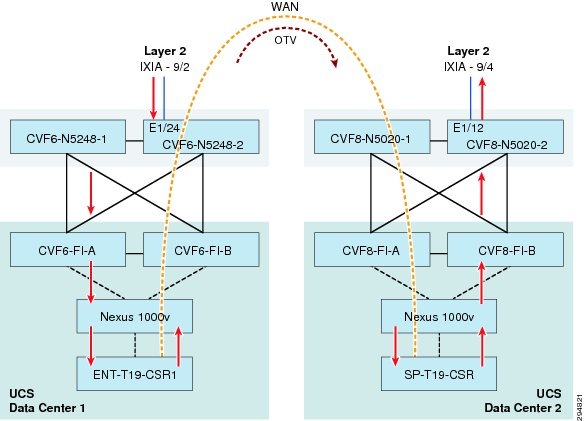
Figure 5-17 shows setup where Ixia ports were used to simulate client-server traffic over OTV. Five bidirectional streams were configured in each of the three tenant server VLANs. In all 15, bi-directional streams were configured. SP-T19-CSR was configured as the gateway for all streams and OTV adjacency server. This resulted in higher CPU on SP-T19-CSR compared to ENT-T19-CSR.
Figure 5-17 OTV Throughput Flow Setup
Testing was done with fixed size and IMIX packets. Fixed size packets were 1024 bytes and IMIX were 7 - 74 byte packet, 4 - 596 byte packet and one 1024 byte packet. Packets per second were increased in each stream to determine the maximum throughput CSR can sustain with negligible loss over more than 30 minutes. CPU performance was monitored for each throughput result below. Results were documented for CSR with 1vCPU and 2.5G and 4vCPU and 4G RAM.
1vCPU, 2.5G RAM
Same VLAN
|
|
|
|
|
|
OTV & BGP |
18000 |
147.4 |
100% |
100% |
OTV, BGP & IPSec (3DES) |
3000 |
24.51 |
77-90% |
74-82% |
OTV, BGP & IPSec (AES) |
13800 |
113 |
100% |
100% |
1 3DES is packet processing intensive. Recommended IPSec encryption is AES |
Packet processing drops compared to fixed size packets, but overall throughput drops considerably with IMIX.
Inter VLAN
4 vCPU, 4G RAM
Same VLAN
Inter VLAN
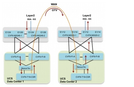
OTV & LISP
Figure 5-18 shows setup where Ixia ports were used to simulate client-server traffic over OTV. Five bidirectional streams were configured in each of the two tenant server VLANs. In all 10, bi-directional streams were configured. East-DC was configured as the OTV adjacency server. For BGP and LISP feature only, MAC filter was enabled on overlay interface to prevent HSRP virtual MACs from being exchanged over OTV bridge-domain. Traffic flow is shown in Figure 5-18.
Figure 5-18 Flow with OTV and LISP
For features with OTV, MAC filter was removed from overlay interface. L3 interface on East-DC was shutdown. Since HSRP virtual MACs were exchanged in OTV bridge-domain, the incoming traffic on East-DC was forced to go over OTV to West-DC. Traffic flow is shown as follows for Figure 5-19.
Figure 5-19 Flow with LISP and OTV
1 vCPU, 2.5G RAM
4 vCPU, 4G RAM
MAC & ARP Scale
MAC Scale—CSR 1000v with 1vCPU and 2.5G RAM was scaled up to 12K MAC addresses.
ARP Scale—CSR with 1vCPU and 2.5G RAM could handle 435 ARPs in one blast. It could successfully populate 3K ARP entries on CSR at rate of 270 ARPs/sec.
Setup—Ixia ports were used to simulate client-server traffic over OTV. 2K bi-directional streams were configured in each of the three tenant server VLANs. In all, 6K bi-directional streams were configured. SP-T19-CSR was configured as the gateway for all streams and OTV adjacency server. All streams ARPed gateway and bi-directional flows were successfully established. 6K Mac addresses on each CSR were exchanged successfully over the OTV bridge-domain.
Figure 5-20 MAC & ARP Flow Setup
 Feedback