Cisco CSR 1000V DRaaS Deployment
Bias-Free Language
The documentation set for this product strives to use bias-free language. For the purposes of this documentation set, bias-free is defined as language that does not imply discrimination based on age, disability, gender, racial identity, ethnic identity, sexual orientation, socioeconomic status, and intersectionality. Exceptions may be present in the documentation due to language that is hardcoded in the user interfaces of the product software, language used based on RFP documentation, or language that is used by a referenced third-party product. Learn more about how Cisco is using Inclusive Language.
- Updated:
- January 28, 2014
Chapter: IP Mobility Design Considerations
IP Mobility Design Considerations
The Cisco Locator/ID Separation Protocol Technology in extended subnet mode with OTV L2 extension on the Cloud Services Router (CSR1000V) will be utilized in this DRaaS 2.0 System. This provides IP Mobility between data centers within SP Cloud for the (VPC to VPC) In-Cloud replication use case.
The Cisco LISP Virtual Machine Mobility (LISP VM-Mobility) solution allows any host to move anywhere in the network while preserving its IP address. The capability allows members of a subnet to be dispersed across many locations without requiring any changes on the hosts and while maintaining optimal routing and scalability in the network. LISP is a network architecture and a set of protocols that implements a new semantic for IP addressing. LISP creates two namespaces and uses two IP addresses: Endpoint Identifiers (EIDs), which are assigned to end-hosts, and Routing Locators (RLOCs), which are assigned to devices (primarily routers) that make up the global routing system. Performing this separation offers several advantages, including:
•![]() Improved routing system scalability by using topologically-aggregated RLOCs
Improved routing system scalability by using topologically-aggregated RLOCs
•![]() Provider-independence for devices numbered out of the EID space (IP portability)
Provider-independence for devices numbered out of the EID space (IP portability)
•![]() Low-OPEX multi-homing of end-sites with improved traffic engineering
Low-OPEX multi-homing of end-sites with improved traffic engineering
•![]() IPv6 transition functionality
IPv6 transition functionality
•![]() IP mobility (EIDs can move without changing - only the RLOC changes!)
IP mobility (EIDs can move without changing - only the RLOC changes!)
LISP is a simple, incremental, network-based implementation that is deployed primarily in network edge devices. It requires no changes to host stacks, DNS, or local network infrastructure, and little to no major changes to existing network infrastructures.
LISP Overview
To understand LISP, it is important to understand the concept of "Location to Identity Separation."
Figure 4-1 Mobility with Location/ID Protocol Technology
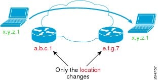
In traditional IP, the IP edge routing subnets are advertised all over the network using either an IGP or an EGP. Advertising any host address (subnet mask /32) occurs rarely; most of the time subnet larger or equal to /24 is used. Because all routes are advertised everywhere and installed in the forwarding plane in IP, limiting the amount of entries is important. By doing so, IP subnets are strictly limited to a geographical area and a subnet is only managed by one pair of router, which is the default gateway. This implies that if a node moves location, then its IP address must be updated accordingly to the local default gateway. This constraint is very strong and cumbersome; in order to escape from it, we see across sites more and more VLAN extension with all the drawbacks this approach can raise.
With LISP, such a constraint disappears; LISP splits the edge ID (EID) from the Routing Location (RLOC), allowing any host to move from location to location while keeping its identity.
LISP architecture is composed of several elements:
•![]() ETR (Egress Tunnel Router)
ETR (Egress Tunnel Router)
–![]() Registers the EID address space for which it has authority
Registers the EID address space for which it has authority
–![]() Identified by one (or more) RLOCs
Identified by one (or more) RLOCs
–![]() Receives and de-encapsulates the LISP frames
Receives and de-encapsulates the LISP frames
•![]() Map Server
Map Server
–![]() The database where all EID/RLOC association are stored
The database where all EID/RLOC association are stored
–![]() Can simply be deployed on a pair of devices for low scale implementation
Can simply be deployed on a pair of devices for low scale implementation
–![]() Or it can be a hierarchy of devices, organized like a DNS system for large scale implementation (LISP-DDT)
Or it can be a hierarchy of devices, organized like a DNS system for large scale implementation (LISP-DDT)
•![]() ITR (Ingress Tunnel Router)
ITR (Ingress Tunnel Router)
–![]() Sends request toward the Map resolver
Sends request toward the Map resolver
–![]() Populates its local map-cache with the learned association
Populates its local map-cache with the learned association
–![]() Responsible for performing the LISP encapsulation
Responsible for performing the LISP encapsulation
•![]() Map Resolver
Map Resolver
–![]() Receives the request and selects the appropriate map server
Receives the request and selects the appropriate map server
•![]() Proxy xTR
Proxy xTR
–![]() The point of interconnection between an IP network and a LISP network, playing the role of ITR and ETR at this peering point.
The point of interconnection between an IP network and a LISP network, playing the role of ITR and ETR at this peering point.
An ETR is authoritative for a subnet, and registers it using a `map-register' message to the map server. When triggered on the data-plane by a packet destined to a remote EID, the ITR performs a "map-request" toward the map-resolver, which forwards it to the right map-server, which then forwards it to the authoritative ETR. The ETR replies to the requesting ITR using a "map-reply" message. The map-reply message contains a list of the RLOCs having the capability to reach the requested EID along with their characteristic in terms of priority of usage and weighted load repartition.
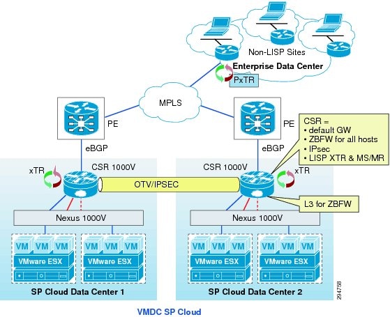
Figure 4-2 shows LISP-ESM deployment using CSR 1000V with in VMDC VSA 1.0 architecture.
Figure 4-2 LISP within VMDC VSA 1.0 Architecture
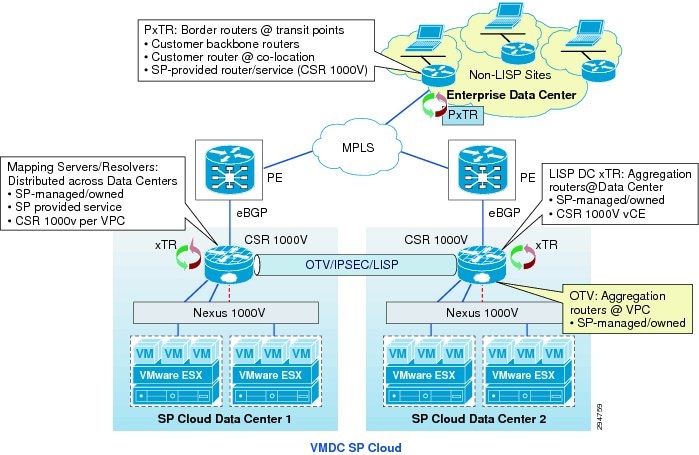
LISP and OTV roles can be deployed in the network as shown in Figure 4-3. CSR 1000V within the VPC on source and destination data centers will be used as the OTV Edge device and LISP xTR. Mapping Server and Resolver will also reside on the CSR 1000V within the VPC at both the data centers in order to eliminate the use of additional devices and to reduce cost. This also improves scalability, as the MS/MR database will be per tenant. Figure 4-2 shows the options for PxTR deployment; the recommendation for PxTR deployment is on CSR1000V at the customer premise. Traffic to server VLANs, which are part of LISP domain, can be directed to the PxTR within the Enterprise.
Figure 4-3 LISP & OTV Roles and Deployment in Network
LISP Deployment Considerations
As an over-the-top technology, LISP has ingress (ITR) and egress (ETR) points. Everything that is in the core between these tunnel end points is overlaid transparently. The only strong requirement about this core is the ability to support greater PDU that includes the LISP header (Figure 4-4). The transport MTU should be 1536 to ensure transparency for 1500 bytes PDU. In case the core is not able to accommodate a larger frame than the basic ones, then LISP ITR is able to support the Path MTU Discovery (PMTUD) approach, sending the ICMP Destination Unreachable message (type 3, code 4) with a code meaning "fragmentation needed and DF set" back to the source of the packet as specified in the original IP header leading the source to adjust packet size to 1444. 1444 is the IP MTU of the original IP packet, but LISP also encapsulates the original IP header, so the payload of a LISP packet (before adding the external IP header) is: 1444 (original payload) + 20 (original Inner IP header) + 8 (LISP header) + 8 (UDP header) + 20 (Outer IP header) = 1500 bytes.
Figure 4-4 LISP Header Format
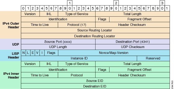
No other strict considerations are mandatory for the core transport. Other aspects like QoS may definitely be needed; in that aspect, LISP is copying the original DSCP towards its tunnel encapsulation header, allowing an end-to-end DiffServ behavior.
The two main LISP benefits to consider are multi-tenancy and mobility. LISP is a pervasive solution, and the placement of the xTR (ITR or ETR) can be seen in multiple places. The most ideal placement for an xTR would be on the CSR 1000V within the VMDC VSA 1.0 data centers. The default gateway resides in the data center and a dedicated CSR 1000V per tenant within the Cloud provides sufficient scalability. With this model, the Cloud would be fully virtualized in multiple instances and mobility across all data center sites. Some factors may add complexity to this simple model and must be taken in consideration.
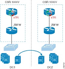
One of them, and probably the most complex, is the insertion of a firewalling service (Figure 4-5). No firewall currently on the market is able to read a LISP-encapsulated frame. This means that to be efficient the firewall must be placed "south" of the xTR in order to apply rules to a clear text traffic outside of any encapsulation. If the firewall is a virtual appliance or is a VSG running in the VM context, then there is no concern as the firewall service is south. If the firewall is running in transparent mode at the access layer, then again there is no concern as the firewall service is south. Within the VMDC VSA 1.0 architecture, as the CSR 1000v provides zone-based firewall capabilities and is also being proposed to be the xTR. Firewall and LISP can coexist, improving the classical VMDC design with virtualization and mobility. For this reason, multi-hop LISP is not required to support the DRaaS use case for failing over workloads from one VPC to another within the Cloud data centers.
Figure 4-5 LISP with Localized Firewall Services
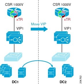
The other consideration is the LISP and SLB integration (Figure 4-6). Within the DRaaS System, the SLB Virtual IP (VIP) is active at one location at a time and represents the LISP EID. The failover of workloads belonging to the load-balanced server farm does not necessarily trigger a VIP move. For this reason, in the case of some servers within a server farm being failed over to the secondary site, they will still have the VIP located at the original site and the traffic flows from that site. In the case of all the servers within a server farm being failed over to a secondary site, the SLB VIP also has to be failed over to the secondary site to provide load-balancing services from the new site.
The failover of the VIP can be performed manually by touching the load-balancers deployed on both sites or to have the load-balancer as part of the virtual protection group along with the servers, which are part of the server farm. The idea is to failover all the servers along with the load balancer that are all contained within a protection group, from one site to another.
The recommendation in this document is to not run the servers that are part of a load-balanced server farm from both primary and secondary sites in a split fashion. The VIP location will get updated in LISP only when moved between the sites along with the servers that are load balanced.
Figure 4-6 LISP and SLB Integration
 Feedback