Cisco CSR 1000V DRaaS Deployment
Bias-Free Language
The documentation set for this product strives to use bias-free language. For the purposes of this documentation set, bias-free is defined as language that does not imply discrimination based on age, disability, gender, racial identity, ethnic identity, sexual orientation, socioeconomic status, and intersectionality. Exceptions may be present in the documentation due to language that is hardcoded in the user interfaces of the product software, language used based on RFP documentation, or language that is used by a referenced third-party product. Learn more about how Cisco is using Inclusive Language.
- Updated:
- January 28, 2014
Chapter: OTV Deployment Considerations
OTV Deployment Considerations
The following OTV deployment topics are considered:
•![]() Virtual Extensible LAN (VXLAN)
Virtual Extensible LAN (VXLAN)
•![]() Use of BDI as Default Gateway on CSR 1000V
Use of BDI as Default Gateway on CSR 1000V
High Availability (HA)
Recommended OTV Deployment should use a single CSR 1000V router at each site, utilizing the VMware HA mechanism for high availability. This will be acceptable for most customers and will prove more cost effective (half as many licenses required).
Virtual Extensible LAN (VXLAN)
The DRaaS System will use traditional dot1q VLANs within the SP VPC instead of the VXLANs because of limitations with VXLAN unicast mode and MAC distribution (CSCuf60643). Dynamic MAC distribution is required for OTV and is not supported with VXLAN.
A VXLAN supports two different modes for flood traffic:
•![]() Multicast Mode—A VXLAN uses an IP multicast network to send broadcast, multicast, and unknown unicast flood frames. Each multicast mode VXLAN has an assigned multicast group IP address. When a new VM joins a host in a multicast mode VXLAN, a Virtual Ethernet Module (VEM) joins the assigned multicast group IP address by sending IGMP join messages. Flood traffic, broadcast, multicast and unknown unicast from the VM is encapsulated and is sent using the assigned multicast group IP address as the destination IP address. Packets sent to known unicast MAC addresses are encapsulated and sent directly to the destination server VTEP IP addresses.
Multicast Mode—A VXLAN uses an IP multicast network to send broadcast, multicast, and unknown unicast flood frames. Each multicast mode VXLAN has an assigned multicast group IP address. When a new VM joins a host in a multicast mode VXLAN, a Virtual Ethernet Module (VEM) joins the assigned multicast group IP address by sending IGMP join messages. Flood traffic, broadcast, multicast and unknown unicast from the VM is encapsulated and is sent using the assigned multicast group IP address as the destination IP address. Packets sent to known unicast MAC addresses are encapsulated and sent directly to the destination server VTEP IP addresses.
•![]() Unicast-Only Mode—A VXLAN uses each VEM's single unicast IP address as the destination IP address to send broadcast, multicast, and unknown unicast flood frames of the designated VTEP on each VEM that has at least one VM in the corresponding VXLAN. When a new VM joins the host in a unicast-mode VXLAN, a designated VTEP is selected for receiving flood traffic on that host. This designated VTEP is communicated to all other hosts through the Virtual Supervisor Module (VSM). Flood traffic (broadcast, multicast, and unknown unicast) is replicated on each VEM's designated VTEP in that VXLAN by encapsulating it with a VXLAN header. Packets are sent only to VEMs with a VM in that VXLAN. Packets that have a unicast MAC address are encapsulated and sent directly to the destination server's VTEP IP address.
Unicast-Only Mode—A VXLAN uses each VEM's single unicast IP address as the destination IP address to send broadcast, multicast, and unknown unicast flood frames of the designated VTEP on each VEM that has at least one VM in the corresponding VXLAN. When a new VM joins the host in a unicast-mode VXLAN, a designated VTEP is selected for receiving flood traffic on that host. This designated VTEP is communicated to all other hosts through the Virtual Supervisor Module (VSM). Flood traffic (broadcast, multicast, and unknown unicast) is replicated on each VEM's designated VTEP in that VXLAN by encapsulating it with a VXLAN header. Packets are sent only to VEMs with a VM in that VXLAN. Packets that have a unicast MAC address are encapsulated and sent directly to the destination server's VTEP IP address.
•![]() MAC Distribution Mode (supported only in unicast mode)—In this mode, unknown unicast flooding in the network is eliminated. The VSM learns all the MAC addresses from the VEMs in all the VXLANs and distributes those MAC addresses with VTEP IP mappings to other VEMs. Therefore, no unknown unicast MAC address exists in the network when the VMs on the VEMs are communicating and controlled by the same VSM.
MAC Distribution Mode (supported only in unicast mode)—In this mode, unknown unicast flooding in the network is eliminated. The VSM learns all the MAC addresses from the VEMs in all the VXLANs and distributes those MAC addresses with VTEP IP mappings to other VEMs. Therefore, no unknown unicast MAC address exists in the network when the VMs on the VEMs are communicating and controlled by the same VSM.

Note ![]() MAC distribution works only for static MAC addresses. If dynamic MAC addresses are found on ports that use VXLANs that operate in MAC distribution mode, syslogs are generated to indicate that MAC distribution does not work with dynamic MAC addresses.
MAC distribution works only for static MAC addresses. If dynamic MAC addresses are found on ports that use VXLANs that operate in MAC distribution mode, syslogs are generated to indicate that MAC distribution does not work with dynamic MAC addresses.
Overlapping VLANs
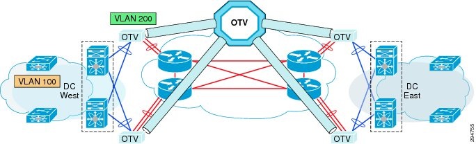
As Enterprises and SPs extend their data centers for Business Continuity or Workload Mobility, it is likely that there will be overlapping VLAN allocations across data centers. Therefore, we could implement a VLAN translation mechanism to overcome this issue, as described in Figure 3-1. This function will translate a local VLAN to remote VLAN in a different site (VLAN in the West Site corresponds to a different VLAN in the East Site).
Figure 3-1 OTV VLAN Translation between Sites
Use of BDI as Default Gateway on CSR 1000V
Currently, Bridge Domain Interface (BDI) is not supported through OTV. In other words, you cannot ping to the BDI interface in a remote OTV site. IS-IS does not advertise BDI MAC address, so OTV does not know how to reach the BDI interface in the remote site. You can only ping to the BDI interface within the same site.
Though it's advisable to use BDI as the default gateway on CSR 1000V, the DRaaS 2.0 System will use the L3 interfaces as default gateways since BDI is not supported for OTV.
OTV and MTUs
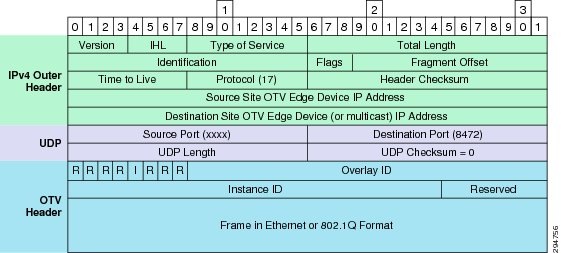
OTV adds 42 bytes in the IP header packets, thus requiring a larger maximum transmission unit (MTU) for traffic to pass (Figure 3-2). Configure the join interface and all L3 interfaces that face the IP core between the OTV edge devices with the highest MTU size supported by the IP core. OTV sets the Don't Fragment (DF) bit in the IP header for all OTV control and data packets so that the core cannot fragment these packets.
Figure 3-2 OTV UDP IPv4 Encapsulation
There are two ways to solve this problem:
1. ![]() Configure a larger MTU on all interfaces where traffic will be encapsulated, including the join interface and any links between the data centers that are in an OTV transport.
Configure a larger MTU on all interfaces where traffic will be encapsulated, including the join interface and any links between the data centers that are in an OTV transport.
2. ![]() Lower the MTU on all servers so that the total packet size does not exceed the MTU of the interfaces where traffic is encapsulated.
Lower the MTU on all servers so that the total packet size does not exceed the MTU of the interfaces where traffic is encapsulated.
 Feedback