Cisco SD-WAN Cloud onRamp for IAAS using Azure Deployment Guide
Available Languages
Bias-Free Language
The documentation set for this product strives to use bias-free language. For the purposes of this documentation set, bias-free is defined as language that does not imply discrimination based on age, disability, gender, racial identity, ethnic identity, sexual orientation, socioeconomic status, and intersectionality. Exceptions may be present in the documentation due to language that is hardcoded in the user interfaces of the product software, language used based on RFP documentation, or language that is used by a referenced third-party product. Learn more about how Cisco is using Inclusive Language.
- US/Canada 800-553-2447
- Worldwide Support Phone Numbers
- All Tools
 Feedback
 Feedback
This document discusses the design and deployment of Cisco SD-WAN Cloud onRamp for IaaS using Azure. The guide focuses on the deployment of secure network connectivity from private network data center and branch locations to one or more Azure VNets using Cisco Cloud onRamp for IaaS. The guide explains at length the platforms deployed within the transit VNet and in the on-premise branches/ datacenter, it highlights the best practices and assists with the successful configuration and deployment of the Cisco Cloud onRamp for IaaS feature. However, the document is not meant to exhaustively cover all options.
This document assumes that the Cisco SD-WAN controllers are already deployed and integrated into vManage NMS, the WAN Edge devices are deployed, and the Cisco SD-WAN overlay network is successfully established. For the device models and software versions used for this deployment, refer to Appendix B and for the device/feature templates, refer to Appendix C.
This document contains four major sections:
● The Define section introduces the Cisco Cloud onRamp for IaaS feature and explains the overall solution, along with the benefits of deploying it.
● The Design section includes the two use cases covered in the guide, along with the design components and considerations for successful SD-WAN Azure integration.
● The Deploy section is divided into two parts. The first part includes the Azure cloud and vManage prerequisites to deploy the Cisco Cloud onRamp for IaaS feature. The second part discusses the automated deployment of the Azure transit VNet to support the two use cases presented within the design section.
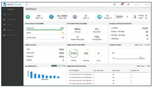
● The Operate section explains some of the common monitoring and troubleshooting capabilities available within the Cisco vManage for the Cloud onRamp for IaaS feature.

The audience for this document includes network design engineers, network operations personnel, and security operations personnel who wish to implement Cisco SD-WAN secure virtual private network (VPN) connectivity from their private networks to one or more Azure virtual networks (VNets).
Define – Cisco Cloud onRamp for IaaS Introduction
Challenges
Network engineers in today’s multicloud world are beginning to understand the benefits of cloud computing services such as Infrastructure as a Service (IaaS), a set of computing resources such as storage and networking components that can be used to host and deliver enterprise applications over the Internet. With IaaS, the on-premise physical data center infrastructure is moved off-premise or extended to a virtualized environment where computing resources are hosted by a public cloud provider such as Amazon Web Services (AWS) or Microsoft Azure. This enables organizations to instantly provision and manage compute infrastructure over the Internet, eliminating the need to procure, install and manage physical hardware appliances.
However, connecting an enterprise network to a cloud provider infrastructure can be challenging since each cloud provider has different models for connectivity. Within the cloud infrastructure, instances or virtual machines are deployed within Azure Virtual Networks (VNets) or Amazon Virtual Private Clouds (VPCs), and connectivity is established via various cloud connectivity models.
The rest of this guide explains the some of the possible design options for Cisco SD-WAN Azure interconnection, with focus on Cisco Cloud onRamp for IaaS design. For details regarding Cisco SD-WAN AWS interconnection refer to the Cisco Cloud OnRamp for IaaS using AWS guide.
Cisco SD-WAN Interconnection with Azure
Within the Azure public cloud, virtual machines or containers are hosted in the cloud infrastructure to extend and interconnect cloud services with the enterprise WAN architecture.
Within the Azure Cloud the following Azure services are used to interconnect with the on-premise Cisco SD-WAN network.
| Azure Terminology |
Definition |
| Azure Resource Groups |
Azure resource groups are a logical collection of resources that include virtual machines, storage accounts, virtual networks, web apps, databases, and/or database servers. |
| Azure Virtual Network (VNet) |
Azure Virtual Networks (VNets) are the fundamental building block for a private network in Azure that contain Azure resources such as Azure Virtual Machines (VM), to securely communicate with each other, the Internet, and to on-premises networks. Note, a VNet is similar to a traditional network that you operate in your own data center, but it brings along it’s additional benefits of Azure's cloud infrastructure such as scale, availability, and isolation. |
| Azure Instances |
Virtual Machines (VMs) or Azure Instances are used to host applications within Azure VNets, they also allow you to deploy Cisco SD-WAN virtual instances within VNets. |
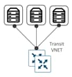
| Transit VNet |
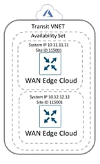
A transit VNet is an Azure VNet used as a transit point for data flows between Azure host VNets as well as between Cisco SD-WAN campus and branch sites and Azure host VNets. The transit VNet is built using a configuration wizard in the vManage NMS. The wizard automates the bring-up of the transit VNet within the Azure public cloud account and the connections between public-cloud applications and the users of those applications in the branches in the overlay network. This VNet contains a pair of WAN Edge virtual devices placed in an availability set for isolating the VMs from each other. These availability sets run across multiple physical servers, compute racks, storage units and network switches. Therefore, when a software or hardware failure occurs only a subset of VM’s fail. Each WAN Edge device is automatically provisioned with the necessary public and private IP addresses, and Network Security Groups. Within the NSGs, rules can be manually configured to block or allow IP traffic flow. The bring up and deployment of transit VNet is explained in depth in the design and deployment section of this guide. |
| Host VNet |
A host VNet is a customer owned virtual network in the Azure cloud, that is manually deployed prior to provisioning the transit VNet. When a transit VNet connects to an application or application provider, it is simply connecting to a host VNet. Each host VNet mapped to the transit VNet, contains a Virtual Network Gateway (VNG) associated to the host VNet’s gateway subnet. Note, while host VNet itself is manually deployed by the user, its associated VNG is automatically provisioned during the cloud onRamp workflow. |
| Virtual Hub |
A virtual hub is a Microsoft-managed virtual network. The hub contains various service endpoints to enable connectivity. |
| Virtual WAN (vWAN) |
The Virtual WAN resource represents a virtual overlay of the customer’s Azure network and is a collection of multiple resources. It contains links to all your virtual hubs that you would like to have within the virtual WAN. |
| Azure Subscription |
Azure Subscription lists out all the subscriptions for which you have role-based access control (RBAC) permissions to manage Azure resources. Each subscription is associated with a subscription ID, a unique alphanumeric string. |
| Azure Active Directory (Azure AD) |
Azure Active Directory (Azure AD) is Microsoft's cloud-based identity and access management service, which helps employees sign in and access resources such as applications within the corporate network and Intranet, along with access to any cloud-based applications developed by the organization. However, remember Azure AD is not similar to an AD on-premise that provides authentication directory policies and other services. Azure AD has only two major services which are identity and access management. |
| Azure AD Application and Service Principal |
Within the Azure AD new applications and service principals are created, that are used with the role-based access control. When you have applications, hosted services, or automated tools that needs to access or modify resources, you can create an identity for the application. This identity is known as a service principal. Roles are assigned to the service principal to maintain control over access to resources. |
| Application ID |
When an application is registered through the Azure portal, an application object, along with the service principal are automatically created in your Azure home directory or tenant. For programmatic sign in access from vManage to your Azure subscription, you pass the directory ID or tenant ID with your authentication request, along with the application ID and secret key. The Application ID or client ID is an identity of the application that Azure AD recognizes. |
| Tenant ID |
The Tenant ID or Directory ID is the identity of the Azure AD in which you have created the Cloud onRamp applications. |
| Client Secret Key |
A client secret key is the secret string that the application uses to prove its identity when requesting a token. |
| Subscription ID |
The subscription ID uniquely identifies the subscription to use Azure services. The Subscription ID, along with the application ID, tenant ID and secret key are required for programmatic sign-in access during the cloud onramp workflow. |
Note, all the Azure ID’s needed for the programmatic sign-in access are explained in depth in the prerequisites section, along with the steps to retrieve these values.
Using the services available in Azure, the following are some of the common Cisco SD-WAN Azure integration.
Cisco SD-WAN Interconnection: Using Azure Virtual WAN (vWAN/ vHub)
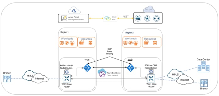
In this design, Azure Virtual WAN and virtual WAN hub(s) serve as a central connection point for host VNets and SD-WAN routers.
There are two possible scenarios for connecting SD-WAN to Azure Virtual WAN:
Born-on-Prem SD-WAN to Azure Virtual WAN: In the first scenario, on-prem physical WAN Edge devices located in branch or data center locations establish IKE-based IPsec tunnel to Azure Virtual Hub (vHub), run BGP and exchange routing information between the cloud infrastructure and the SD-WAN network using BGP-OMP redistribution.
Born-in-Cloud SD-WAN to Azure Virtual WAN: In the second scenario, virtual WAN Edge device hosted in Azure VNets establishes IKE-based IPsec tunnels to Azure Virtual Hub (vHub), run BGP and exchange routing information between the cloud infrastructure and the SD-WAN network using BGP-OMP redistribution.
For the steps to deploy this design option, refer to the following guide:
● Interconnection Cisco SD-WAN and Azure Virtual WAN Guide (vWAN)
Currently, automation within the Cloud onRamp for IaaS feature is only available for connecting Azure host VNets to the Cisco SD-WAN through a transit VNet, and not for Azure Virtual WAN.
Cisco SD-WAN Interconnection: using Cloud onRamp for IaaS
One of the most popular and widely used options is the Cisco Cloud onRamp for IaaS feature. The key differentiator for Cloud onRamp for IaaS is automation. The entire solution is completely automated – the end user simply needs to enter his Azure subscription ID, along with the tenant ID, application ID and secret key in the related vManage section, discover Azure hosted virtual networks and workloads, and define two routers for interconnection. Cisco Cloud onRamp for IaaS brings up a fully deployed Azure hosted transit VNet containing a pair of Cisco WAN Edge routers, extends the fabric of the Cisco SD-WAN overlay network into the public cloud via the transit VNet, and allows Cisco SD-WAN branches to connect directly to public-cloud application providers.
The rest of this solution focuses on the SD-WAN Azure Integration using Cloud onRamp for IaaS.
About the Cloud onRamp for IaaS using Azure Solution
Using Cisco SD-WAN Cloud onRamp for IaaS, you can automatically spin up virtual WAN Edge router instances via Cisco vManage in a specific region of the public cloud. These virtual instances become part of the SD-WAN overlay and establish data plane connectivity to the WAN Edge routers located in the branch and/or the datacenter. As a result, secure end-to-end connectivity is established between the workloads in the cloud, physical branches and data centers.
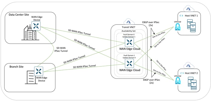
In this design, cloud hosted virtual networks connect via IPsec VPN connections to a redundant pair of virtual WAN Edge devices within a transit VNet. The transit VNet is in turn part of the SD-WAN Secure Extensible Network (SEN), which provides direct VPN connectivity to branch and Data Center (DC) sites within the private network.
Benefits of deploying Cisco Cloud onRamp for IaaS transit VNet Design
Some of the key benefits of deploying the Cloud onRamp feature includes the following,
| Automated Infrastructure in Public Cloud (Extend SD-WAN)
|
The entire solution is automated. The deployment of the transit VNet, bring-up procedure of WAN Edge virtual routers, and interconnection with Host VNets is done automatically by entering Azure IDs (Tenant ID, Subscription ID, Application ID) and the client secret key into the vManage GUI for programmatic sign-in access. Note, the same tasks can also be done manually, wherein the network administrator can log in to the appropriate public cloud management console, create the transit VNet, spin up redundant virtual routers, and interconnect the host VNets. However, it could take several hours and requires multiple tasks to be completed in at least two different GUIs: vManage and the public cloud management console. With Cisco Cloud onRamp for IaaS, the same task can be completed in approximately 15 minutes with less chance of human error. |
| Policy Control (Policy Framework)
|
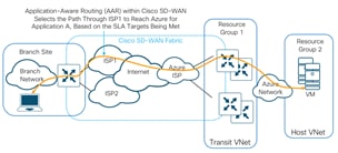
Users can fully utilize Cisco SD-WAN capabilities in the cloud. This allows all on-premise data center and branch locations which are part of the Cisco SD-WAN fabric to leverage features available both on Cisco vManage and within the cloud provider. Some of the features that can be leveraged on Cisco SD-WAN fabric include: Application Aware Routing (AAR) to choose the best transport network to reach the IaaS public cloud provider. Embedded security features such as IPS/IDS, Stateful Firewall, AMP, URL Filtering to protect and filter data traffic before leaving the on-premise network to the Internet cloud. |
| Management Plane (Unified Control)
|
Configure and manage Cloud onRamp for IaaS using the Cisco vManage NMS server. A configuration wizard in the vManage NMS automates the bring-up of the transit VNet to the customers Azure public cloud account and automates the connections between the public-cloud applications and the users of those applications at branches in the Cisco SD-WAN overlay network. |
| Reduce OPEX (Cost Effective)
|
Expenses shift from fixed costs for hardware, software, and data center infrastructure to variable costs based on the usage of compute resources available on Azure public cloud. |
Design – Cisco Cloud onRamp for IaaS Use Case and Feature Overview
The design section is organized in the following order:
● Use Case #1 – Full Connectivity
● Use Case #2 – Segmentation to the Cloud Provider
● Design Components and Consideration
◦ Supported Platform and Software
◦ Azure Design Considerations
◦ Mapping of a Host VNet to Transit VNet
◦ Firewall Port Considerations
◦ Cisco Cloud onRamp for IaaS Workflow
Use Case #1 - Full Connectivity
In this use case, all entities within an organization have full connectivity to the public cloud resources deployed by the organization.
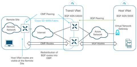
This design has the host VNets mapped to a single VRF or service-side VPN. In the example figure, all traffic from service-side VPN 1 of the WAN Edge devices deployed in both the datacenter and branch are routed over to the applications (virtual machines) in the Azure host VNets, along with communication between the VMs in the Host VNets.
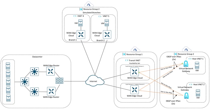
Note: Cisco SD-WAN branches are deployed within the Azure cloud only for testing purposes. If you plan on deploying virtual SD-WAN branch networks within the Azure platform, these WAN Edge devices can run any Cisco SD-WAN image available in the Azure Marketplace. You can alternatively also download a Cisco SD-WAN image from CCO and upload this to Storage Service within Azure and use this image to deploy WAN Edge devices within the Host VNets.
Regarding size of the Virtual images that can be hosted within Azure branch VNets, refer to products page in Microsoft Azure and select the Cisco WAN Edge.
Use Case #2 - Segmentation to the Cloud Provider
In this use case, different entities within an organization have connectivity to specific public cloud resources deployed by the organization.
This design leverages Cisco SD-WAN segmentation, therefore isolating traffic between different host VNets. In this example design, one of the host VNet is mapped to VRF 1 or service-side VPN 1; and the other host VNet is mapped to VRF 2 or service-side VPN 2. As traffic across the SD-WAN overlay carries the VRF or VPN label, LAN traffic from the datacenter can be configured to communicate only with VRF 1, while branch traffic communicates with VRF 2.
This use case helps provide traffic isolation.
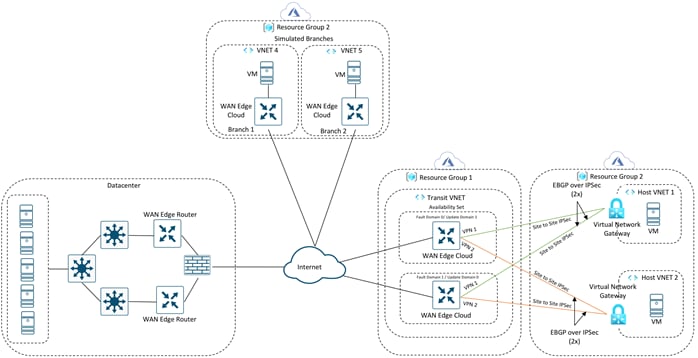
Note: The Azure branches are there only for testing purposes.
Design Components and Consideration
The rest of the design section focuses on the platforms, software, and features to be considered while deploying the SD-WAN Azure cloud integration using Cisco SD-WAN Cloud onRamp for IaaS feature.
Supported Platforms and Software
Cloud onRamp for IaaS using Azure is supported on vManage from version 18.2 onwards. Refer to the table below to understand the platforms that support the feature. Note, this list does not account for any product development changes made since the release of code version 20.1.
Table 1. Supported Platforms
| Platform |
Azure Transit VNet |
On-premise DC/Branch |
| Cisco – ISR4k |
N |
Y |
| Cisco – ISR1k |
N |
Y |
| Cisco – ASR1k |
N |
Y |
| Cisco – ENCS (ISRv) |
N |
Y |
| Cisco – CSR1k |
N |
Y |
| Cisco – vEdge Cloud |
Y |
Y |
Azure Design Considerations
Before extending the on-premise network to Azure using the Cloud onRamp for IaaS feature ensure to configure, setup and gather details required to complete the onRamp process from the Azure public cloud. The rest of this section shares all necessary details associated with the Azure cloud account.
Design a Transit VNet
Using the Cloud OnRamp for IaaS feature available in vManage, a transit VNet is automatically provisioned in the Azure public cloud containing pair of WAN Edge virtual devices.
The transit VNet design can be split into two parts:
● Preparation of WAN Edge Devices: To use the Cloud onRamp feature you must have at least two unused WAN Edge cloud devices available in the vManage devices list, with device templates attached to them. When the transit VNet is deployed these two devices will be hosted within it.
● Automated bring up of Transit VNet: The second part includes the automated creation of the transit VNet, along with the provisioning of a pair of WAN Edge cloud devices to this new VNet.
Preparation of WAN Edge Devices
Design device templates comprising of all the required feature templates to be associated with the WAN Edge cloud devices in the transit VNet. These templates are attached to the two valid unused WAN Edge cloud devices.
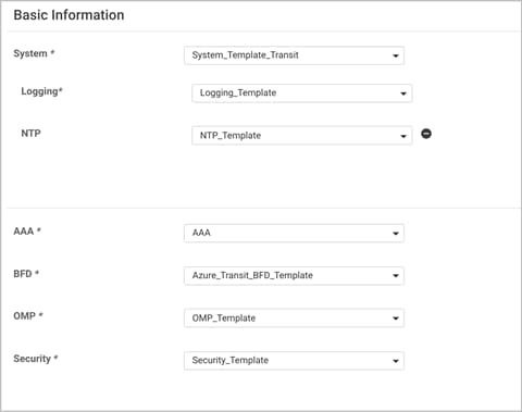
The following are the feature templates attached to the WAN Edge cloud devices:
● System Template: This feature template includes configurations like system-IP, site-id, hostname, IP addresses, and so on, defined as editable variables in the template. It is important to note that, while designing the system template for a pair of WAN Edge devices in a transit VNet, the system-IPs are different but the site-IDs are configured the same.
For instance, a transit VNet containing two devices - WAN Edge device 1 and WAN Edge device 2 are configured with the same site, such as 115001.
Also, within the system template, by default, gateway tracking is enabled to determine whether the next hop for the static route is reachable before adding that route to the device's route table. It is recommended to disable "track-default-gateway" in the system template. Keeping this feature enabled may not affect the provisioning process, but the overall configuration of the routers may be incorrect.
● NTP Template: The NTP server used in this deployment is time.nist.gov. With Cisco Cloud onRamp, the Cisco WAN Edge Cloud routers within the Azure transit VNet are automatically configured such that interface ge0/0 is part of VPN 0 and gets its IP address via DHCP (ip dhcp-client). The Azure DHCP server which allocates the IP address to ge0/0 will also provide the DNS server IP address. Therefore, a hostname can be configured and translated to an IP address by the Azure DNS server. For this deployment guide the NTP server time.nist.gov was used.
● AAA Template: This feature template is crucial and must be configured within the WAN Edge routers, in order to understand the username/password required to access the devices via SSH once the WAN Edge cloud routers are built and configured within the Transit VNet.
● BFD Template: This template is used to specify the BFD app-route multiplier and poll interval and specify the hello and BFD multiplier for each transport. In this deployment, the only color used is of Biz-Internet, since Cisco Cloud onRamp only provisions physical Internet connections to the transit VNet (VPN 0, interface ge0/0). The BFD hello interval has been made a variable. For this deployment guide, the BFD hello interval was set to 10,000 milliseconds with a multiplier of 3. You should select the appropriate BFD hello interval to balance the requirement for fast convergence against the cost of additional data transfer charges in your deployment.
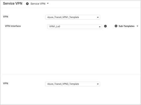
● VPN Template: This feature template is created to separate VPN feature templates for each VPN. For the WAN Edge devices in transit VNet, a separate feature template is created for VPN 0, VPN 512 and service side-VPN (For ex. VPN 1 and VPN 2). To enable Cloud onRamp for IaaS feature only a minimum of one service VPN template is required. If you like to segment traffic to service-side VPN 1 and service-side VPN 2, attach separate service-VPN templates for each service side VPN within the device template. Within this template, enable IPv4 routing, ECMP keying etc. Within OMP, both BGP and connected routes are advertised within OMP so that the IP addresses of the Loopback interfaces, which are a part of VPN 1/ VPN 2, are also visible across the network.
| Technical Tip |
| The cloud onRamp workflow configures a default static route to null 0 on the WAN Edge cloud router to be advertised by BGP. Advertising the null0 route via OMP to other WAN Edge devices in your network can be disruptive. However, if for any reason you have additional static routes defined within the Cisco SD-WAN Edge routers, requiring the redistribution of static routes into OMP within the transit VNet, then you may need to look at filtering out the static default route through policies applied to the SD-WAN network. |
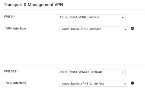
● VPN Interface Template: This feature template is created to configure interface parameters for the WAN Edge cloud routers. Separate VPN Interface templates are configured for interfaces under VPN 0, VPN 512 and service-side VPNs (VPN 1, VPN 2 among others).
With Cisco Cloud onRamp for IaaS, the Cisco WAN Edge cloud routers within the Azure transit VNet are automatically configured such that interface ge0/0 is in VPN 0 and interface eth0 is in VPN 512 and both of them get their IP addresses via DHCP (ip dhcp-client).
Although, no physical interfaces are attached to a service-side VPN, within the service side VPN template, BGP routes are advertised within OMP.
| Technical Tip |
| The templates associated within vManage NMS attached to the Cisco SD-WAN Edge devices are not updated with the additional configuration resulting from the loopback, IPsec connections and BGP routing to the host VNets. Instead, the configurations of the Cisco SD-WAN Edge devices within the transit VNet are dynamically modified by Cisco Cloud onRamp for IaaS. Because of this, you must exercise some caution if you wish to modify the configuration of the Cisco SD-WAN Edge routers within a transit VNet after you have mapped host VNets to it. For example, if you add a BGP feature template to a service interface within the device template for the Cisco SD-WAN Edge router, you have to use BGP ASN 64600 in the feature template. This is the BGP ASN that Cisco Cloud onRamp for IaaS uses for the transit VNet when mapping host VNet to the transit VNet. Network devices can only be part of a single BGP ASN at one time. |
Automated Bring-up of Transit VNet
At the time of configuring the cloud onRamp feature via the vManage GUI you must the region, choose the image, VM size and the appropriate chassis UUID to be associated with the virtual WAN Edge device to be provisioned within the new transit VNet.
● Software Image: In a vManage NMS running Cisco SD-WAN code 19.2/ 20.1, a virtual device within transit VNet can be automatically deployed running either of these Cisco SD-WAN code versions - 19.1, 18.4, 18.3, 18.2.
| Technical Tip |
| Cloud onRamp for IaaS with Azure does not support the CSR1k. As of 19.2/20.1 vManage only vEdge Cloud devices can be successfully provisioned within the transit VNet. |
● Size of WAN Edge Device: The size of a Virtual Machine (VM) within your transit VNet is selected at the time of deploying Cloud onRamp for IaaS feature. Choose the size based on the overall workload that you want to support. The size that you choose then determines factors such as processing power, memory, and storage capacity. Azure offers a wide variety of sizes to support many types of uses. Azure charges an hourly price based on the VM's size and operating system.
vManage NMS running version 19.2.2, lets you choose between either of the following sizes for your WAN Edge device pairs hosted in your transit VNet. Both the sizes provide a high memory-to-core ratio.
Table 2. WAN Edge Virtual Device Sizes
| Size |
RAM |
Core |
| Standard F8 (8 vCPU) |
16GiB |
8 |
| Standard F4 (4 vCPU) |
8GiB |
4 |
For per size pricing details, refer to the Azure pricing chart.
Note: For this guide throughput has not been tested.
● Transit VNet CIDR: Within the Cisco Cloud onRamp workflow, specify an IPv4 CIDR block range for the transit VNet. The IPv4 CIDR range you configure is automatically sub-netted to create the necessary subnets within the transit VNet. Cisco Cloud onRamp automatically creates the Azure logical components such as the transit VNet, its associated subnets, network interfaces and publicly routable IP addresses.
By default, Azure proposes the CIDR - 10.0.0.0/16 to be used for the new transit VNet. It is best to avoid using such a large address block and rather divide this network into smaller chucks for each VNet. For this deployment, the CIDR for transit VNet is set to 10.0.1.0/24.
Mapping of a Host VNet to Transit VNet
For successful mapping of host VNet to the transit VNet, make sure to choose the appropriate service-side VPN label, a valid IPsec CIDR address, Azure acceptable BGP AS Numbers and host VNet gateway subnet.
● Choosing the Service-Side VPN: Mapping of a host VNet to a transit VNet is done per service-side VPN. You can either place all host VNets in the same VPN or leverage segmentation by placing host VNets in separate VPNs. As traffic across the SD-WAN overlay carries the VRF or VPN label details, LAN traffic from Data Centers (DCs) and branches can be configured to either communication only all VPNs or to a single VPN.
| Technical Tip |
| When a host VNet is selected to be mapped to a transit VNet, it is mapped to only one service-side VPN within the Cisco SD-WAN WAN Edge device. However, a single service-side VPN can be mapped to multiple host VNets. The number of Host VNets supported per Cisco SD-WAN Edge virtual device pair depends on the overall throughput requirements. |
● IPsec Tunnel CIDR: Each Cisco WAN Edge virtual router in the transit VNet builds two site-to-site IPsec tunnels for redundancy to the Azure virtual network gateway (VNG) in the host VNet. Since there are two Cisco WAN Edge routers in the transit VNet, the total number of IPsec tunnels in the transit VNet is four. The IPsec tunnels that connect the WAN Edge routers in the transit VNet to the host VNet run IKE for secure connection. For Azure, the IPsec tunnels run IKE version 2.
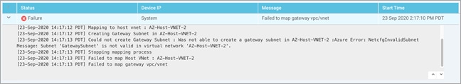
The IPsec IP addresses must be network addresses in the /30 subnet, unique across the overlay network, and not a part of the host VNet CIDR. If they are part of the host VNet CIDR, Azure will return an error while attempting to create VPN connections to the transit VNet.
At this stage, you must also enter a /32 loopback address, which is used later during BGP peering. Ensure this IP address is unique.
● BGP ASN: Over secure IPsec tunnels, Cisco SD-WAN Edge routers establish BGP connectivity to the Host VNets Virtual Network Gateway (VNG) and exchanges BGP (Border Gateway Protocol) routes. WAN Edge virtual routers learn host VNet networks over BGP and redistribute routes into Overlay Management Protocol (OMP).
By default, the BGP ASN number configured within the WAN Edge virtual devices is 64600. The BGP ASN you enter within the Cloud onRamp for IaaS workflow is the BGP ASN assigned to the Virtual Network Gateway (VNG) associated with the host VNet. This ASN number can be any number acceptable within Azure cloud. To note the acceptable Azure BGP ASN number refer to the document - https://docs.microsoft.com/en-us/azure/vpn-gateway/vpn-gateway-bgp-overview.
● Host VNet Gateway: The Host VNet Gateway Subnet is defined based on the overall subnet associated with the Azure host VNet. For example, if the host VNet subnet is defined as 10.25.2.0/24, then, the Host VNet Gateway Subnet is a subset of that such as 10.25.2.128/25. If the configured gateway subnet is invalid, Azure will return an error.
Once all the details are entered, the mapping process is initiated. A new gateway subnet is created in the host VNet, followed by a new Local Network Gateway (LNG) in Azure. Note, the LNG simply represents the WAN Edge virtual device in the network. A new Virtual Network Gateway (VNG) is created within the host VNet and this VNG is associated with the Host VNet’s gateway subnet. Therefore, each VNG (associated with the host VNet) contains two public IP addresses for site-to-site VPN connection, private IP addresses, and a BGP ASN number for BGP peering.
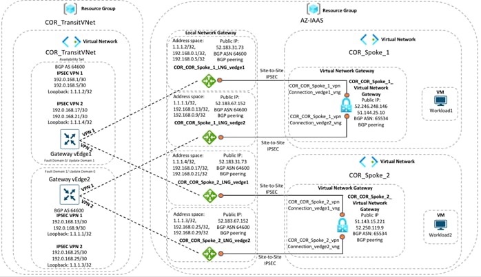
In the transit VNets WAN Edge devices, logical IPsec tunnel interfaces are built within the chosen service-side VPN (E.g. VPN 1). The IPsec tunnel source is set to the VPN 0 Ge0/0 private IP address and the tunnel destination is set to the Virtual Network Gateway’s (VNG’s) public IP address. Within these devices two static routes are configured within the service-side VPN (For. E.g. VPN 1/ VPN 2), to route traffic to the Virtual Network Gateway (VNG) (10.25.2.133 and10.25.2.132) via the IPsec interfaces and establish BGP peering over the IPsec tunnel using the source of the WAN Edge device’s loopback addresses.
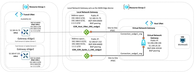
In the example figure, segmentation is leveraged and the IPsec tunnel CIDR is configured in the range 192.168.x.x/30. For each of the WAN Edge device, tunnels sourced from the VPN0 Ge0/0 IP address (10.0.1.36) and VPN0 Ge0/0 IP address (10.0.1.37), with the destination set as VNG’s public IP addresses (52.246.248.146 and 51.144.25.10).
Static routes are configured in both the WAN Edge device’s service-side VPN, for reachability to the VNG’s IP addresses (10.25.2.132 and 10.25.2.133), via the IPsec tunnel interfaces. Each WAN Edge device forms BGP neighbors with these VNG IP addresses (10.25.2.132 and 10.25.2.133) via loopback interface (1.1.1.1 and 2.2.2.2) configured during the mapping process.
Therefore, each WAN Edge router, neighbors with both the IP addresses of the Virtual Network Gateway.
● One BGP peering between the WAN Edge devices loopback IP and the IP address 1 (10.25.2.132) of Virtual Network Gateway.
● Another BGP peering between the WAN Edge devices loopback IP and the IP address 2 (10.25.2.133) of Virtual Network Gateway.
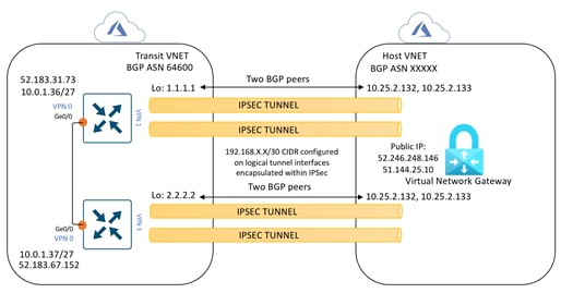
So, each mapped host VNet has a total of four BGP peers – two BGP peers configured on one Cisco SD-WAN Edge router, and two BGP peers configured on the other Cisco SD-WAN Edge router. Hence, there are four potential paths from the transit VNet to the host VNet.
These BGP routes are then re-distributed into OMP within the WAN Edge devices, which then advertises the OMP routes to the vSmart controllers in the domain. vSmart controllers act as a route reflector and sends the OMP routes as route updates to other WAN Edge devices part of the Cisco SD-WAN overlay. Therefore, establishing data plane communication between them and connectivity between the branch/ Datacenter to the Host VNet in Azure cloud.
Note, redistribution of OMP routes into BGP is not necessarily needed, as the WAN Edge devices advertise network 0.0.0.0/0 to the Virtual Network Gateway (VNG) within the host VNet.
| Technical Tip |
| Cloud onRamp for IaaS does not cover scenarios where the customer wants to include Security NVAs in their Cloud environment, and consequently, for such deployment’s customers will need to build all IaaS components and SD-WAN Edge routers manually (or via scripting using AWS CLI or Azure PowerShell). |
Once the mapping process completes successfully, you still need to open all necessary ports within the Azure Network Security Groups (NSGs) associated with the WAN Edge virtual devices NIC modules hosted in the Azure transit VNet.
Firewall Port Considerations
Firewall ports are opened within the on-premise gateway firewall and within the Network Security Group (NSG) associated with the Azure WAN Edge devices to allow for the formation of secure sessions between the WAN Edge routers and the controllers.
Within the cloud onRamp workflow Azure Network Security Groups (NSGs) are automatically created and associated with the transit VNets network interface and they contain security rules that filter the network traffic to and from the device. These rules are classified as inbound security rules and outbound security rules. The inbound security rule allows or denies inbound network traffic to other resources, while the outbound security rule allows or denies outbound network traffic from other resources. For each rule, you can specify source and destination, port, and protocol.
Note, all NSGs have a set of default rules. These default rules cannot be deleted, but since they have the lowest possible priority, they can be overridden by the rules that you create. Note, by default no incoming or outgoing ports are open, you need to manually open these ports.
At a minimum the following UDP ports must be opened to establish control plane and data plane connections.
Table 3. UDP ports for SD-WAN device connections
| Source Device |
Security Rules |
| WAN Edge (DTLS) |
UDP 12346+n, 12366+n, 12386+n, 12406+n, and 12426+n, where n=0-19 and represents the configured offset |
For more details regarding firewall port considerations, please refer to the Cisco SD-WAN Design Guide.
Cisco Cloud onRamp for IaaS Workflow
The order of workflow for the Cloud onRamp for IaaS feature is explained below, along with concurrent real time audit logs collected from the vManage GUI.
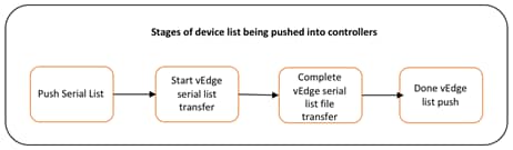
Template Built: Within the Cloud onRamp for IaaS workflow, feature and device templates are built and the WAN Edge serial numbers are validated.
When WAN Edge serial numbers are validated the device serial list is pushed and processed into vBond, vManage, vSmart.
Template Push: The device template is attached to the WAN Edge virtual devices and the device template is pushed into the devices. During this step the following occurs,
● Device Validation: During device validation, the vManage checks if the WAN Edge device scheduled for template push is active. In the following example, the WAN Edge devices are validated.
WAN Edge Device 1: Chassis-ID - bc6827c6-041a-4afa-806d-433efcd2ed7f
WAN Edge Device 2: Chassis-ID - e6bad40d-afec-4ce7-87d2-c23a08bafcd4
Starting Checks.
Validating if device scheduled for template push are active
DeviceIP: -, uuid: bc6827c6-041a-4afa-806d-433efcd2ed7f is not connected to vManage
DeviceIP: -, uuid: e6bad40d-afec-4ce7-87d2-c23a08bafcd4 is not connected to vManage
Sending message to vmanage:172.27.0.14
Published messages to vmanage(s)
Checks completed.
● The device template is attached to the device. Since the WAN Edge devices are yet to be configured and deployed using the Cloud onRamp for IaaS workflow, the devices are currently offline and unreachable.
Configuring device with feature template: OnRamp_Transit_WAN_edge_Template
Generating configuration from template
Checking and creating device in vManage
Device is offline
Updating device configuration in vManage
Configuration template OnRamp_Transit_WAN_edge_Template scheduled to be attached when device comes online. To check the synced state, click Configuration > Devices > Device Options
Bootstrap Configuration File: At this stage a minimum cloud-INIT bootstrap configuration file is also generated from the vManage for the WAN Edge virtual devices. This bootstrap configuration file consists of a one-time password (OTP) token needed for the WAN Edge device authentication and validation. In the following example, bootstrap configuration files are generated for the vEdge cloud devices with Chassis-ID - bc6827c6-041a-4afa-806d-433efcd2ed7f and Chassis-ID - e6bad40d-afec-4ce7-87d2-c23a08bafcd4.
Bootstrap config generated for vEdge cloud-ead1954a-087e-4571-b747-0665fb330406
Bootstrap config generated for vEdge cloud-0d777876-18a4-4e1f-ba0d-2297ba6d5185
Note, at this stage the devices are still not up and running, with the required configuration and certificates.
vManage Azure API Access: For programmatic access from the vManage NMS to the Azure account, the Tenant ID, Client ID, Secret Key and Subscription ID associated with your Azure account are entered.
Note, these credentials are saved for API access into the Azure account.
Successfully saved credentials for accountId:5f70cd2b-baee-4c43-889a-71bb1e8a0efc
Creation of Gateway VNet Process: vManage NMS builds Azure constructs through API calls:
● At first a new resource group is provisioned. Within the resource group, the transit VNet is deployed in the selected Azure location and associated to the same account ID/ subscription ID entered for access from vManage to Azure.
Creating transit VPC/VNet: COR_TransitVNet
Creating Transit Vnet in westus2 under subscription 5f70cd2b-baee-4c43-889a-71bb1e8a0efc
Resource Group Name: COR_TransitVNet
● Resources deployed within the resource group include,
◦ An availability set in which the WAN Edge virtual devices are to be provisioned
Creating Resources - This can take up to 10 minutes
Created resource : COR_TransitVNet AvailabilitySet
◦ Network Security Groups (NSG) where ports and IP addresses are either allowed or denied access
Created resource : COR_TransitVNet NSG
◦ Subnet, IP addresses and virtual network modules for VPN 512 and VPN 0 network interfacesare deployed.
Within transport VPN 0, an interface is configured with both public and private IPs
Within management VPN 512, an interface is configured with both public and private IPs.
At this point no logical IPsec interfaces are configured within the service-side VPN.
Created resource : GatewayVedge1_management_ip
Created resource : GatewayVedge1_transport_ip
Created resource : GatewayVedge2_management_ip
Created resource : GatewayVedge2_transport_ip
Created resource : COR_TransitVNet
Created resource : GatewayVedge1
Created resource : GatewayVedge2
Created resource : GatewayVedge1_management_nic
Created resource : GatewayVedge1_service_nic
Created resource : GatewayVedge1_transport2_nic
Created resource : GatewayVedge1_transport_nic
Created resource : GatewayVedge2_management_nic
Created resource : GatewayVedge2_service_nic
Created resource : GatewayVedge2_transport2_nic
Created resource : GatewayVedge2_transport_nic
Created resource : GatewayVedge2_osdisk
Created resource : GatewayVedge1_osdisk
Gateway VNet creation process finished successfully : COR_TransitVNet
Mapping Host VNet to Transit VNet: Within the Cloud onRamp for IaaS workflow, at first you map a single host VNet to the transit VNet.
Cisco Cloud onRamp for IaaS uses Azure APIs to automatically create a gateway subnet within the Azure host VNet, followed by the creation of Local Network Gateway (LNG). Note, each LNG in the functions as a WAN Edge virtual router.
A Virtual Network Gateway (VNG) is deployed in the host VNet and a redundant pair of site-to-site VPN connections are established between the Local Network Gateway (LNG) and the Virtual Network Gateway (VNG). Each Azure Site-to-Site VPN connection consists of a pair of IPsec tunnels established to the same Local Network Gateway (LNG). Therefore, a total of four IPsec tunnels is established from each host VNet to the transit VNet.
The Azure Site-to-Site VPN Connections are mapped to the WAN Edge routers in the transit VNet, through the service-side VPN of the WAN Edge routers.
IPsec protected logical tunnel interfaces are automatically configured in the service VPN between the Cisco SD-WAN Edge routers and the IPsec endpoints of the Azure Site-to-Site VPN Connections associated with the Azure Virtual Network Gateway (VNG) at the host VNet.
Static routes and BGP AS number 64600 are configured in the service-side VPN in the WAN Edge virtual routers placed in the transit VNet, along with network 0.0.0.0/0 (static null 0) advertised to the BGP neighbor definitions corresponding to the endpoints of the Azure Site-to-Site VPN Connections in the Azure Virtual Network Gateway (VPN GW) at the host VNet. These BGP routes are redistributed into OMP.
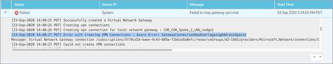
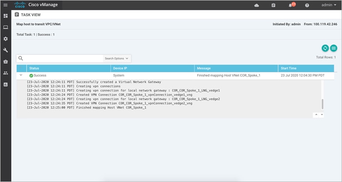
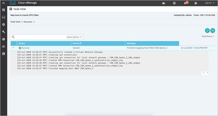
The Audit Logs that correspond to this workflow is as given below. Here the transit VNet is mapped to the host VNet COR_Spoke_1.
Mapping Host VNet in 5f70cd2b-baee-4c43-889a-71bb1e8a0efc to Transit VNet in 5f70cd2b-baee-4c43-889a-71bb1e8a0efc
Location : westus2
Mapping to host vnet : COR_Spoke_1
Creating Gateway Subnet in COR_Spoke_1
Creating local network gateways
Creating COR_COR_Spoke_1_LNG_vedge1
Created local network gateway : COR_COR_Spoke_1_LNG_vedge1
Creating COR_ COR_Spoke_1_LNG_vedge2
Created local network gateway : COR_ COR_Spoke_1_LNG_vedge2
Creating Virtual Network Gateway. This could take up to 45 minutes
Successfully created a Virtual Network Gateway
Creating vpn connections
Creating vpn connection for local network gateway : COR_COR_Spoke_1_LNG_vedge1
Created VPN Connection COR_COR_Spoke_1_vpnConnection_vedge1_vng
Creating vpn connection for local network gateway : COR_COR_Spoke_1_LNG_vedge2
Created VPN Connection COR_COR_Spoke_1_vpnConnection_vedge2_vng
Finished mapping Host VNet COR_Spoke_1
Device Validation: Device validation occurs again and vManage checks if the WAN Edge devices scheduled for template push is active.
WAN Edge Device 1: Chassis-ID - bc6827c6-041a-4afa-806d-433efcd2ed7f
WAN Edge Device 2: Chassis-ID - e6bad40d-afec-4ce7-87d2-c23a08bafcd4
Starting Checks.
Validating if device scheduled for template push are active
DeviceIP: -, uuid: bc6827c6-041a-4afa-806d-433efcd2ed7f is not connected to vmanage
DeviceIP: -, uuid: e6bad40d-afec-4ce7-87d2-c23a08bafcd4 is not connected to vmanage
Sending message to vmanage:172.27.0.14
Published messages to vmanage(s)
Checks completed.
Note, the logs show that the devices are not connected to vManage yet, as all the necessary UDP/ TCP ports must be opened within the,
● Azure Network Security Group (NSG) associated to the NIC of each WAN Edge device
● On-premise gateway firewall for device authentication.
vManage as CA: Once the firewall ports are open and return routes are configured, the WAN Edge devices use the cloud-init file generated by the vManage during the bootstrap process to authenticate itself to vBond and form control connections with vManage and vSmart. During this process, the following processes occur.
● Cisco vManage acts as a certificate authority (CA), handing the Cisco SD-WAN Edge device a certificate. vManage generates CSR for both the WAN Edge devices.
CSR generated for WAN edge
UUID: e6bad40d-afec-4ce7-87d2-c23a08bafcd4
Device IP: 10.1.0.137
● The generated CSR is signed by vManage for the WAN Edge devices.
CSR Signed by vManage-b8a4fa09-bf86-4b1a-bb9e-9eb80f365226for vEdge cloud-e6bad40d-afec-4ce7-87d2-c23a08bafcd4
● Then root cert chain file is transferred and installed into both the vEdge cloud devices from vManage NMS.
Transferred root cert chain file to vEdge
UUID: e6bad40d-afec-4ce7-87d2-c23a08bafcd4
Device IP: 10.1.0.137
Installed root cert chain on vEdge
UUID: e6bad40d-afec-4ce7-87d2-c23a08bafcd4
Device IP: 10.1.0.137
● Certificate installation is completed on the WAN Edge device.
Certificate Installation successful for vEdge cloud by vManage-b8a4fa09-bf86-4b1a-bb9e-9eb80f365226
UUID: e6bad40d-afec-4ce7-87d2-c23a08bafcd4
Device IP: 10.1.0.137
Certificate signed by vManage: b8a4fa09-bf86-4b1a-bb9e-9eb80f365226
● The Cisco SD-WAN Edge device then uses this certificate to re-authenticate to vBond and establish permanent control connections to vManage and vSmart. Once the control connections are established, vSmart updates the Cisco SD-WAN Edge device with policy information, OMP routing information and IPsec keys for establishing connections to other Cisco SD-WAN Edge devices, etc. This ends the cloud onRamp for IaaS workflow.
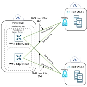
Mapping Additional Host VNets to Transit VNet
Once the Cloud onRamp for IaaS workflow is complete, you can optionally map additional host VNets to the transit VNet. This provides connectivity between the host VNets. Alternatively, individual host VNets can be mapped to separate SD-WAN service VPNs at the transit VNet - if network segmentation is required.
Here’s the overall illustration of a scenario in which two host VNets are mapped to the same transit VNet.
Prerequisites - Cisco Cloud onRamp for IaaS using Azure
The processes explained in the prerequisites section are as given below:
Process 1: Azure Prerequisites
Process 2: vManage NMS and Transit VNet Prerequisites
Process 1: Azure Prerequisites
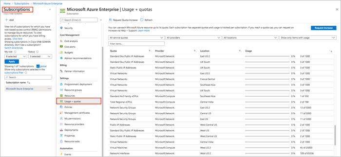
Procedure 1: Check Resource Usage limits
Check the Azure limits associated with your account (by going to your subscription in the portal to ensure that the following resources can be created in your account:
● 1 VNet, which is required for creating the transit VNet
● 1 Availability set, required for Virtual Machine distribution in the transit VNet
● 6 Static Public IP addresses associated with the transit vEdge Cloud routers
● 1 Azure Virtual Network Transit and 2 Static Public IP Addresses for each host VNet
● 4 VPN connections for mapping each host VNet
Step 1. Log into the Azure portal.
Step 2. Navigate to Subscriptions and select Usage + quotas.
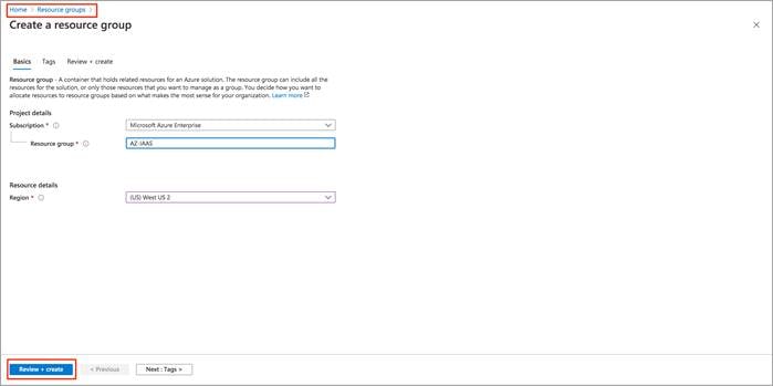
Procedure 2: Deploy Resource Groups on Azure
The resource group is a container that includes all the resources for the solution, or only those resources that you want to manage as a group. This resource group contains the Host VNet, any associated Network Security Groups (NSGs), subnets among others.
In this deployment Resource Group AZ-IAAS is deployed in West US 2.
Step 1. Navigate to Home > Resource groups.
Step 2. Within the resource group, create a new resource group. Here, set the Subscription type, enter a name for the new Resource Group and enter the Region under resource details. Click on Review + Create.
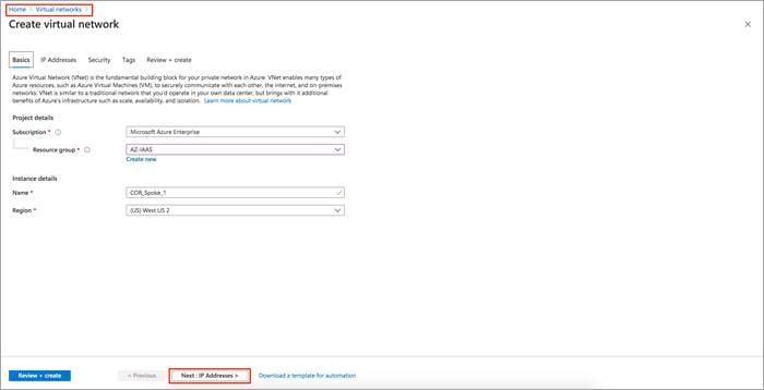
Procedure 3: Deploy Host VNets within the Resource Group
A host VNet is a customer-owned virtual network in the cloud. It is a logical isolation of the Azure cloud dedicated to your subscription. Each host VNet you create has its own CIDR block and can be linked to other VNets and on-premises networks as long as the CIDR blocks do not overlap.
Step 1. Navigate to Home > Virtual Networks.
Step 2. Under the section Basics, choose your Azure Subscription and the newly created Resource Group. Next, Enter Instance details, such as the instance Name and choose the location/ Region in which the instance will be deployed. The new VNet COR_Spoke_1 is deployed within this Resource Group
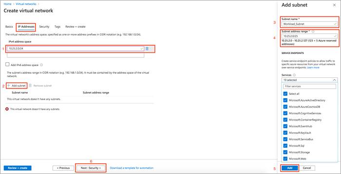
Step 3. Select Next: IP Addresses > to specify the virtual networks address space.
Generally, Azure proposes use 10.0.0.0/16 as the CIDR. Try to avoid using this and divide the subnet into smaller chucks. In this guide, host VNet CIDR address space is set as 10.25.2.0/24 and subnet within this CIDR is defined as 10.25.2.0/25.
Step 4. Under the IP Addresses section, enter your host VNet CIDR address space under IPv4 address space.
Step 5. Click on the + Add subnet to add the new Subnet name and Subnet address range. Then, click Add.
Step 6. Review all the changes made and click Next: Security >.
You can also enable Security features such as DDoS Protection, Firewall etc. and associate Tags to the VNet based on your network. In this deployment, these features were kept default.
Step 7. Review all the changes made and click Create.
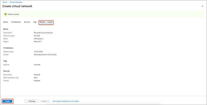
Note: The Virtual Network Gateways are automatically added once Cisco Cloud onRamp for IaaS feature is enabled. You need not deploy it using Azure services.
Procedure 4: Deploy Virtual Machines hosted within the host VNets on Azure
Any Azure Instance (s) can be deployed within the Host VNet.
Step 1. Launch the Microsoft Azure portal.
Step 2. Navigate to Home > Virtual Machine and create a VM in the host VNet COR_Spoke_1.
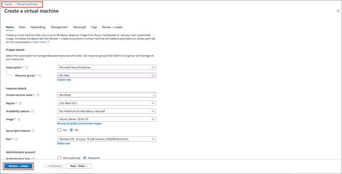
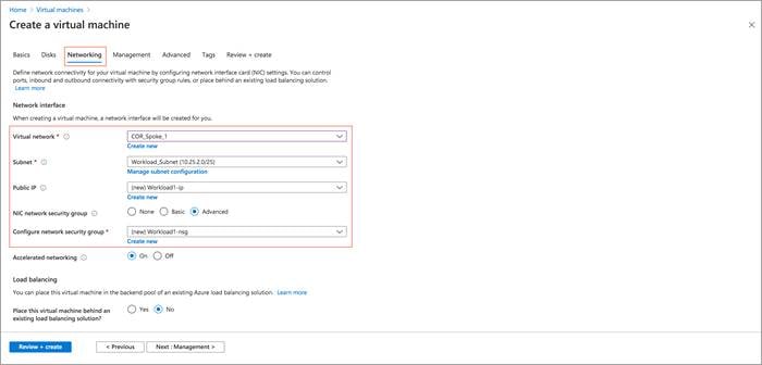
During this process you can create a new subnet or choose the subnet created earlier, also create new public IPs and associate new Network Security Groups (NSG) to the devices virtual Network Interface Cards (NIC) within the Networking tab.
Procedure 5: Gather Subscription ID
One of the four IDs needed to provide the vManage with programmatic access to your Azure Subscription is the Subscription ID.
Note, the Subscription ID is a GUID that uniquely identifies your subscription to use Azure services.
Step 1. Navigate to Subscriptions service and click on the three dots located on the right side of the page (...)
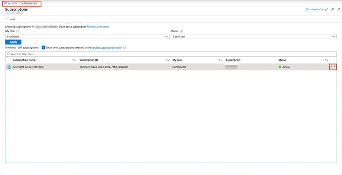
Step 2. Copy the Subscription ID to a notepad.
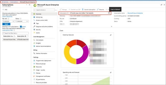
Table 4. Gathered 1 out of 4 values needed during the Cloud onRamp Workflow
| Section |
Value |
| Tenant ID |
|
| Subscription ID |
5f70cd2b-XXXX- XXXX - XXXX - XXXX XXXX XXXX |
| Client ID |
|
| Secret Key |
|
Procedure 6: Application Registration
In Azure, application objects describe the application to the Azure AD, allowing the service to know how to issue tokens to the application based on its settings. These objects can be created in multiple ways, the chosen method here is that of Application Registrations in Azure portal.
Sub-Procedure 1: Check Azure AD Permissions
You must have sufficient permissions to register an application with your Azure AD tenant, and to assign the application a role in your Azure subscription.
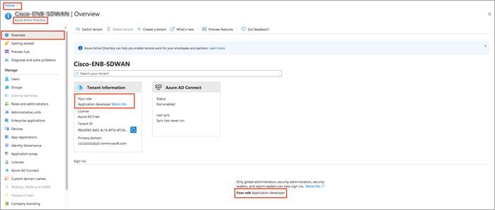
Step 1. Select Azure Active Directory, and note your role. Only roles with admin privileges can register applications in your Azure AD tenant.
For details on Azure roles refer to the Azure roles and privileges guide.
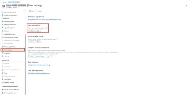
| Technical Tip |
| If you assigned User role, you must make sure that non-administrators can register applications. If it is set to User role, then select User settings and check the App registrations setting. This value can only be set by an administrator. If set to Yes, any user in the Azure AD tenant can register an app. If the app registrations setting is set to No, only users with an administrator role may register these types of applications. See available roles and role permissions to learn about available administrator roles and the specific permissions in Azure AD that are given to each role. Also, If your account is assigned the User role, but the app registration setting is limited to admin users, ask your administrator to either assign you one of the administrator roles that can create and manage all aspects of app registrations, or to enable users to register apps.
|
Sub-Procedure 2: Check Subscription Permissions
As explained previously, when you have applications that needs to access or modify resources, you create an identity for the application. This identity is known as a service principal. Access to resources are restricted by the roles assigned to your service principal, giving you control over which resources can be accessed.
Therefore, after having verified your role and privileges associated with the Azure AD, also make sure your Azure subscription account has Microsoft.Authorization/*/Write access to assign a role to an Azure AD application. This action is associated only with the Owner role or User Access Administrator role. If your account is assigned the Contributor role, you do not have adequate permission. You will receive an error when attempting to assign the service principal a role.
Step 1. Select the subscription you want to create the service principal in and select My permissions. Then, select Click here to view complete access details for this subscription.
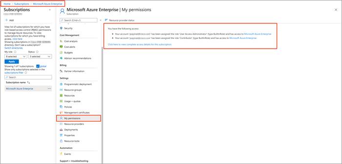
Step 2. Select View my access to view your assigned roles, and determine if you have adequate permissions to assign a role to an AD app. If not, ask your subscription administrator to add you to User Access Administrator role. In the following image, the user is assigned the User Access Assignment role, which means that user has adequate permissions.
Sub-Procedure 3: Register an Application with Azure AD and Create a Service Principal
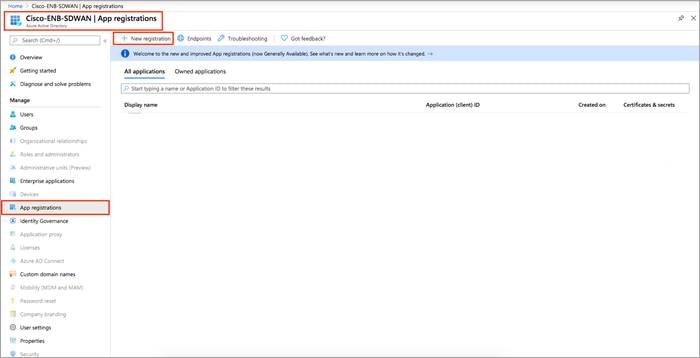
Step 1. To create an application ID, select Azure Active Directory and in the sub-menu, click App registrations.
Step 2. Click New registration.
Step 3. In the Name field, enter a descriptive name such as CloudonRampIAASGuide. The rest of the tabs can be left as default. After setting the values, select Register.
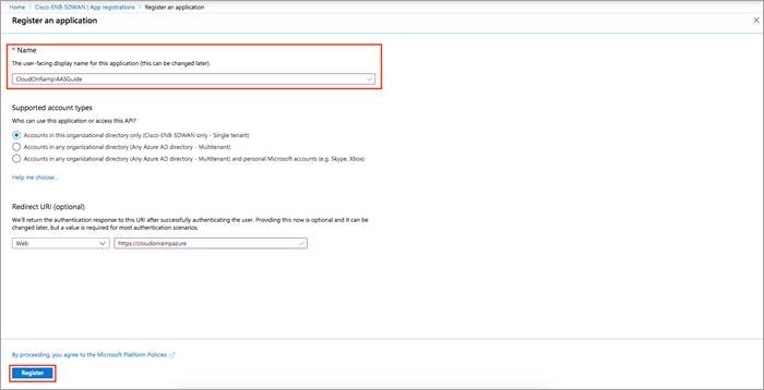
You've created your Azure AD application and service principal.
Sub-Procedure 4: Assign Contributor role to the Application
To access resources in your subscription, you must assign a role to the application. You can set the scope at the level of the subscription, resource group, or resource. Permissions are inherited to lower levels of scope.
vManage NMS uses the values gathered to access Azure via REST API, and to enable this we need to set up appropriate permissions or access privileges. The Owner, Contributor, Reader and User Access Administrator are the four fundamental built-in roles. For example, adding an application to the Contributor role means granting it full access to manage all resources, but this does not allow you to assign roles in Azure RBAC.
The built-in role Contributor is used here that lets you access and manage everything except granting access to resources.
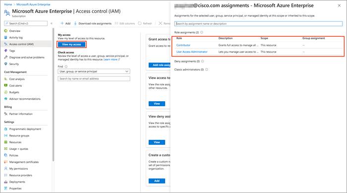
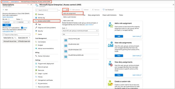
Step 1. In the Azure portal, select the level of scope you wish to assign the application to. Therefore, navigate to All services > Subscriptions > Microsoft Azure Enterprise | Access Control (IAM)
Step 2. To retrieve Azure credentials, you must create an App Registration in Azure with Contributor privileges. To do so, click on Access control (IAM) from the left side and click on the + Add to select Add role assignment.
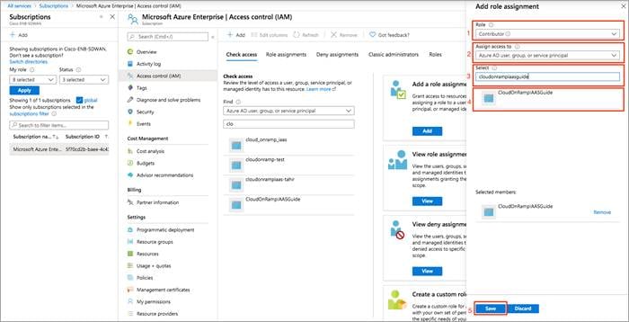
Step 3. From the Role drop-down menu, select Contributor.
Step 4. From the Assign access to drop-down, select the default value Azure AD user, group, or service principle.
Step 5. In the Select tab, enter the name of the Application you had initially created. Your application will populate below.
Step 6. Select the application and click Save.
Access to service principal is set up.
Cisco Cloud onRamp uses API calls to create the Azure transit VNet with two Cisco vEdge Cloud router instances, and to map existing Azure host VNets to the transit VNet. The next section shows how to get the values needed to sign in programmatically from vManage.
Procedure 7: Get Tenant ID and Application ID for Signing In
For the programmatic sign in access from vManage NMS, you need to pass both the tenant ID with your authentication request and the application ID. You also need either a certificate or an authentication key. In this example, an authentication (secret) key is created. To get these values, follow the steps below:
Step 7. When a user signs up for a Microsoft cloud service subscription such as Microsoft Azure, a dedicated instance of Azure AD (Active Directory) is created for the user’s organization. This Azure AD instance is partitioned into separate tenants. Each tenant is a dedicated, isolated instance of the Azure Active Directory service, owned and managed by an organization.
From the Azure AD service, you can get the Tenant ID or Directory ID, which is the identity of the Azure AD in which you have created the Cloud onRamp applications and the Application ID or Client ID which is an identity of the application that Azure AD recognizes.
Copy the Directory (tenant) ID and Application (client) ID to a notepad. You will use those IDs later in your vManage to connect to your Azure Application.
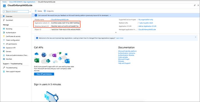
Table 5. Gathered 3 out of 4 values needed for the Cloud onRamp Workflow
| Section |
Value |
| Tenant ID |
f95d3f42-fe02-4c16-8f7d-4f126df87754 |
| Subscription ID |
5f70cd2b-XXXX- XXXX - XXXX - XXXX XXXX XXXX |
| Client ID |
0c33f63d-ebde-4d2f-915e-69871bbf00ae |
| Secret Key |
|
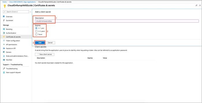
Procedure 8: Authentication - Create a new Secret key for the Cisco Cloud onRamp Application
Gather the Cloud onRamp secret key that the ‘CloudonRampIaaSGuide’ application can use to authenticate itself to AD.
Step 1. In the summary screen of App registrations, click Certificates & Secret.
Step 2. In the screen, click on + New client secret.
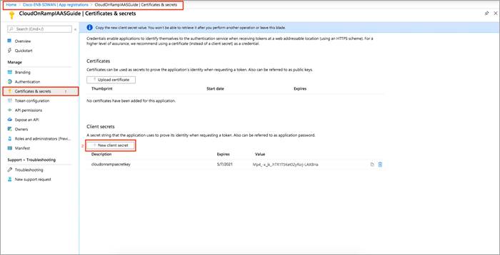
Step 3. Enter a Description and Expiry time period. Click, Add.
Step 4. Click on the copy button [] to copy the value of secret key to a notepad. This value is used later in vManage.
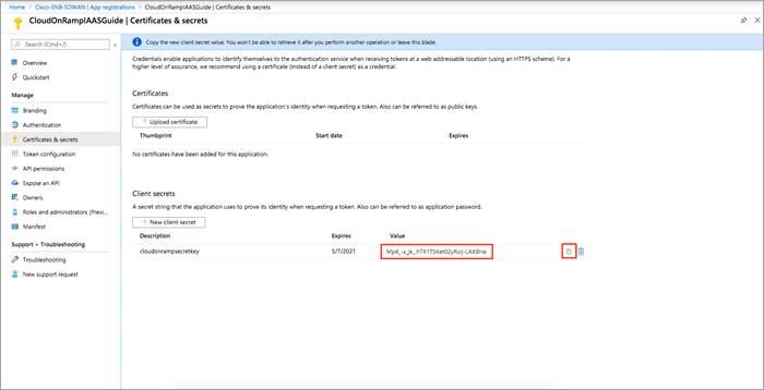
Table 6. Gathered 4 out of 4 values needed during the Cloud onRamp Workflow
| Section |
Value |
| Tenant ID |
f95d3f42-fe02-4c16-8f7d-4f126df87754 |
| Subscription ID |
5f70cd2b-XXXX- XXXX - XXXX - XXXX XXXX XXXX |
| Client ID |
0c33f63d-ebde-4d2f-915e-69871bbf00ae |
| Secret Key |
1lIPm_JKlih_C~-TK_8h3-Ugws4cmDIy4 |
Procedure 7: Firewall Ports are opened in both Azure and in the on-premise gateway firewall
Lastly, remember to open firewall ports to establish DTLS connection with the on-premise controllers and to establish control plane connections with the vSmart controller. For details on the ports opened, refer to the design section of this document.
Process 2: vManage NMS and Transit VNet Prerequisites
Before you can configure Cloud onRamp for IaaS, you must properly provision the vManage NMS.
Procedure 1: Verify Internet Access from vManage
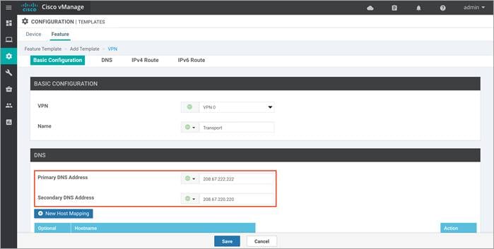
Step 1. Make sure that your vManage server has access to the Internet and that it has a DNS server configured so that it can reach Azure Cloud. To enable DNS server configuration, you can do this either within the VPN feature template associated with your vManage device template or do it via CLI.
Option 1: If your vManage is configured using the vManage device templates, then a DNS server config is added in the VPN feature template. To configure a DNS server in vManage VPN 0, enter the IP address of a DNS server, and then save the edited feature template.
Option 2: If your vManage is configured manually via CLI, then login to vManage GUI and navigate to Tools > SSH Terminal. Click on the vManage server from the device group and enter the following commands:
vManage# conf t
Entering configuration mode terminal
vManage(config)# vpn 0
vManage(config-vpn-0)# dns 208.67.222.222 primary
vManage(config-vpn-0)# dns 208.67.220.220 secondary
vManage(config-vpn-0)# commit
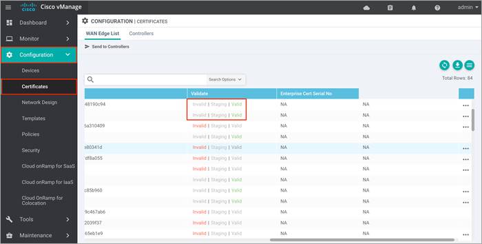
Procedure 2: Verify you have two unused Cisco vEdge Cloud routers in vManage
Step 1. Ensure that two vEdge Cloud routers that are to be used to bring up the Cisco Cloud onRamp for IaaS are added to the vManage NMS. These two routers are later deployed in Azure public cloud in their own VNet, and together they form the transit VNet, which is the bridge between the Cisco SD-WAN overlay network and Azure cloud applications.
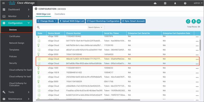
| Technical Tip |
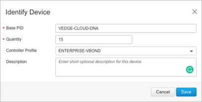
| If you do not have 2 unused Cisco vEdge Cloud routers within the WAN Edge list, login to Cisco Plug and Play portal. Under the Devices tab, click Add Software Device to add the devices to the portal. To add a vEdge Cloud device, enter Base ID as VEDGE-CLOUD-DNA and Quantity as 2 or more, and select your Controller Profile from the drop-down option. Click Save and then Submit.
Verify that the devices are successfully added to the Plug-and-Play portal and associated with the vBond controller profile. For step-by-step details on device onboarding, please refer the SD-WAN WAN Edge Onboarding Deployment Guide. |
Step 2. Ensure that the vManage NMS is synchronized to the current time. To check the current time, click the Help (?) icon in the top bar of any vManage screen.
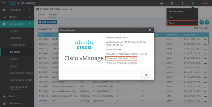
Step 3. The Timestamp field shows the current time. If the time mentioned is incorrect, configure the vManage server’s time to point to an NTP time server, such as the Google NTP server. To do this either an NTP feature template can be associated within the vManage device template or you can configure it manually via CLI.
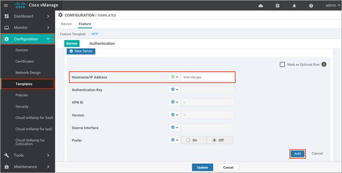
Option 1: To configure or update the vManage NTP feature template, enter the Hostname/ IP Address of an NTP server, and then attach the new or updated feature template within the vManage device template.
Option 2: To configure NTP server via CLI, login to vManage GUI and navigate to Tools > SSH Terminal. Click on the vManage server from the device group and enter the following commands:
vManage(config)# sys
vManage(config-system)# ntp
vManage(config-ntp)# server time.nist.gov
vManage(config-server-time.nist.gov)# version 4
vManage(config-server-time.nist.gov)# com
Commit complete.
Procedure 3: Configure a device template for the Cisco vEdge Cloud routers
You must have a device template assigned within Cisco vManage NMS to the two Cisco vEdge Cloud routers that Cisco Cloud onRamp for IaaS provisions within the transit VNet. Apart from configurations in VPN 0, you need at least one service-side VPN and the Management VPN 512 configured within the device template.
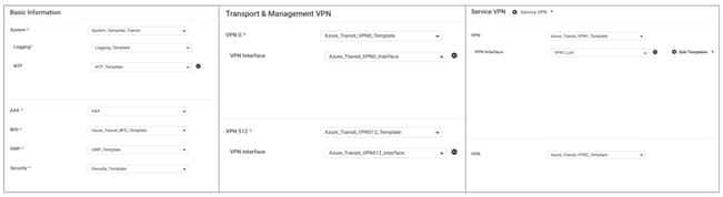
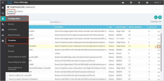
Step 1. Build a device template with feature templates similar to the figure below. For drill-down details of the feature templates used in this deployment refer to the Appendix C.
Step 2. Next, go to Configuration > Templates and select the Device tab.
Step 3. Find the desired device template (Onramp_Transit_WAN_edge_Template).
Step 4. Select the … to the right of the template, and from the drop-down menu select Attach Devices.
An example is shown in the following figure.
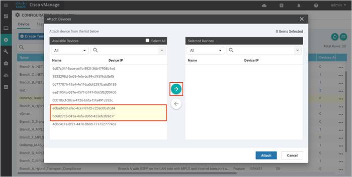
A pop-up window listing the available devices to be attached to this configuration will appear. The list of available devices contains either the hostname and IP address of a device if it is known through vManage; or it contains the chassis serial number of the devices that have not yet come up on the network and are unknown by vManage. Cisco WAN Edge Cloud routers are assigned a chassis serial number although there is no physical chassis.
Step 5. Select the devices you want to apply the configuration template to and select the arrow to move the device from the Available Devices box to the Selected Devices box.
You can select multiple devices at one time by simply clicking each desired device.
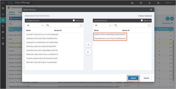
Step 6. Click the Attach button.
A new screen will appear, listing the devices that you have selected.
● onRamp-vEdge-Cloud1: bc6827c6-041a-4afa-806d-433efcd2ed7f
● onRamp-vEdge-Cloud2: e6bad40d-afec-4ce7-b7d2-c23a08bafcd4
6. Find the first Cisco vEdge Cloud router, select … to the far right of it, and from the drop-down menu select Edit Device Template.
For this deployment guide the first Cisco vEdge Cloud router has a chassis serial number of 6bad40d-afec-4ce7-87d2-c23a08bafcd4. An example is shown in the following figure
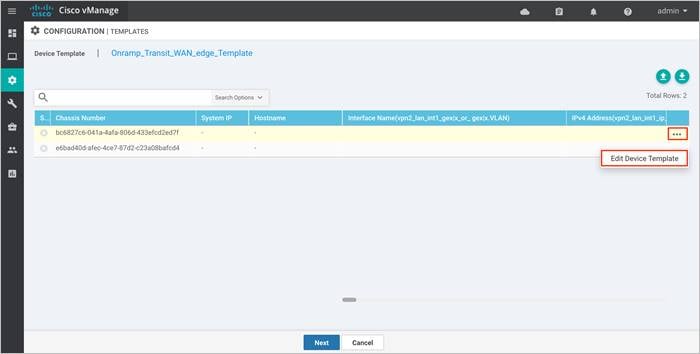
A pop-up screen will appear with a list of variables and empty text boxes. There may also be variables with check boxes to check/uncheck for on/off values.
Step 7. Fill in the values of the variables in the text boxes.
This deployment guide uses a custom device template onRamp_Transit_WAN_Edge_Template for Cisco vEdge Cloud routers deployed by using Cisco Cloud onRamp within the Azure transit VNet.
The following template is deployed on Chassis Number - bc6827c6-041a-4afa-806d-433efcd2ed7f
| Variables |
Value |
| Hostname (system_host_name) |
onRamp_vEdge-Cloud1 |
| System IP (system_system_ip) |
10.1.0.136 |
| Site ID (system_site_id) |
115001 |
| IPv4 Address(vpn1_lo0_int_ip_addr_maskbits) |
10.1.0.136/32 |
| Interface Name(vpn512_mgt_int_mgmt0_or_gex) |
eth0 |
| Interface Name(vpn0_inet_int_gex) |
ge0/0 |
| Shutdown(vpn1_lan_int1_shutdown) |
|
| Bandwidth Upstream(vpn0_inet_int_bandwidth_up) |
1000000 |
| Bandwidth Downstream (vpn0_inet_int_bandwidth_ down) |
1000000 |
| Timezone (UTC -7) |
America/Los_Angeles |
| Latitude(system_latitude) |
37.409284 |
| Longitude(system_longitude) |
-97.335 |
| Device Groups(system_device_groups) |
Azure |
| Port Offset(system_port_offset) |
1 |
| Port Hopping(system_port_hop) |
|
| Hello Interval (milliseconds)(bfd_internet_bfd_hello_interval) |
10000 |
| Address(vpn0_inet_next_hop_ip_addr) |
10.0.1.33 |
The following template is deployed on Chassis Number - e6bad40d-afec-4ce7-b7d2-c23a08bafcd4
| Variables |
Value |
| Hostname (system_host_name) |
onRamp_vEdge-Cloud2 |
| System IP (system_system_ip) |
10.1.0.137 |
| Site ID (system_site_id) |
115001 |
| IPv4 Address(vpn1_lo0_int_ip_addr_maskbits) |
10.1.0.137/32 |
| Interface Name(vpn512_mgt_int_mgmt0_or_gex) |
eth0 |
| Interface Name(vpn0_inet_int_gex) |
ge0/0 |
| Shutdown(vpn1_lan_int1_shutdown) |
|
| Bandwidth Upstream(vpn0_inet_int_bandwidth_up) |
1000000 |
| Bandwidth Downstream (vpn0_inet_int_bandwidth_ down) |
1000000 |
| Timezone (UTC -7) |
America/Los_Angeles |
| Latitude(system_latitude) |
37.3541 |
| Longitude(system_longitude) |
-121.9552 |
| Device Groups(system_device_groups) |
Azure |
| Port Offset(system_port_offset) |
1 |
| Port Hopping(system_port_hop) |
|
| Hello Interval (milliseconds)(bfd_internet_bfd_hello_interval) |
10000 |
| Address(vpn0_inet_next_hop_ip_addr) |
10.0.1.33 |
Deploy - Cisco Cloud onRamp for IaaS using Azure
This section covers the steps to deploy Cisco Cloud onRamp feature using IaaS.
Configuration Workflow
● Make sure the prerequisites explained previously are added.
● The Cloud onRamp for IaaS feature uses APIs to automate the following process:
◦ Configure and deploy Azure transit VNets with all necessary subnets, network interface, network security groups, public IP addresses etc. This process also includes the instantiation of a pair of redundant Cisco WAN Edge Virtual routers within the transit VNet.
◦ Discover and map host VNets to the transit VNet via Azure site-to-site connections. Note, one Host VNet must be mapped to the transit VNet within the workflow that creates the transit VNet. Any remaining host VNets can be added later.
Process 1: Deploy a Transit VNet using Cisco Cloud onRamp for IaaS
This section discusses the procedures for deploying a transit VNet using Cisco Cloud onRamp for IaaS.
Procedure 1: Login to vManage and navigate to Cisco Cloud onRamp for IaaS
Step 1. Login to the vManage web console.
Login to the vManage web console using the IP address or fully qualified domain name of your vManage instance. For example:
https://vManage_ip_addr_or_FQDN:8443/
Step 2. In the navigation panel on the left side of the screen, select Configuration > Cloud onRamp for IaaS. If this is the first time you’re configuring the Cloud onRamp for IaaS feature, then no Azure or AWS cloud instances will appear, and the initial screen should look similar to the figure below.
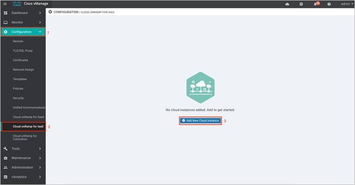
| Technical Tip |
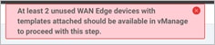
| You must have at least two unused Cisco WAN Edge Cloud routers with templates attached available in vManage to deploy the Cloud onRamp with IaaS feature. If unavailable, then the following error message appears at the top page, and you will able unable to proceed with the deployment of this feature.
|
Procedure 2: Select the Cloud Provider and Configure Access Credentials
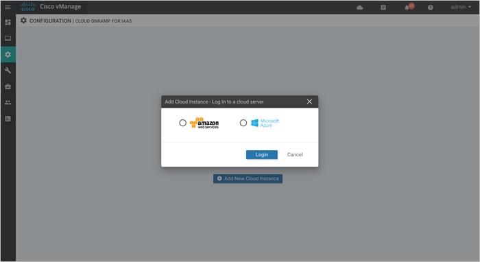
Step 1. Click the Add New Cloud Instance button in the bottom center of the screen.
This will begin the workflow for you to add a new cloud instance.
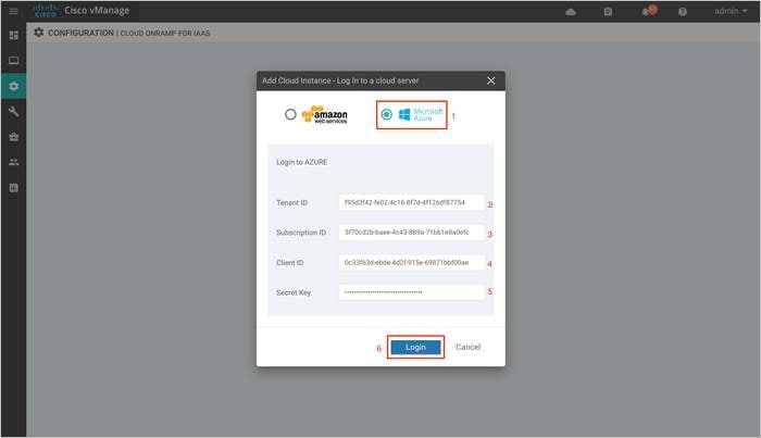
Step 2. Click on the radio button next to Microsoft Azure cloud provider and enter the Tenant ID, Subscription ID, Client ID and the Secret Key gathered from the steps in the Azure prerequisites.
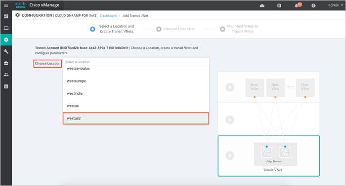
Procedure 3: Select a Location and Create Transit VNets
After you have entered the Azure IDs and secret key, the cloud instance configuration wizard opens. This wizard consists of three screens that you use to Create Transit VNets, Discover Host VNet, and Map Host VNets to Transit VNets.
A graphic on the right side of each wizard screen illustrates the steps in the cloud instance configuration process. Steps not yet completed are shown in light gray. The current step is highlighted within a blue box. Completed steps are indicated with a green checkmark and are shown in light orange.
Step 1. Choose the location where you want to deploy your SD-WAN Transit VNet.
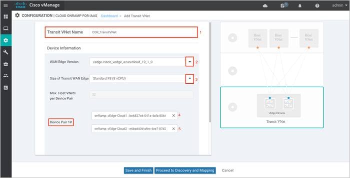
Step 2. Next, enter a name for your new Transit VNet, followed by the Device Information.
Device Information:
● Software Version of WAN Edge devices: In a vManage NMS running Cisco SD-WAN code 19.2/ 20.1, a virtual device within transit VNet can be automatically deployed running either of these Cisco SD-WAN code versions - 19.1, 18.4, 18.3, 18.2.
Choose the WAN Edge Version from the drop-down menu. The cloud routers in the transit VNet will be deployed running the chosen SD-WAN software version.
● Size of VM: At this point you also select the size of Virtual Machine (VM) within your transit VNet. Choose the size based on the overall workload that you want to support. vManage NMS running version 19.2.2, lets you choose between either size.
◦ Standard F8 (8 vCPU)
◦ Standard F4 (4 vCPU)
For pricing details refer to the Azure pricing chart.
Choose the Size of Transit WAN Edge from the drop-down menu. The WAN Edge cloud routers will be deployed with the chosen size. Standard F8 (8vCPU) is the chosen size in this deployment. Before choosing the size, refer to Azure f-series cost vs memory.
● The Device Pair 1# lists the two WAN Edge cloud devices, that were logically attached to a device template.
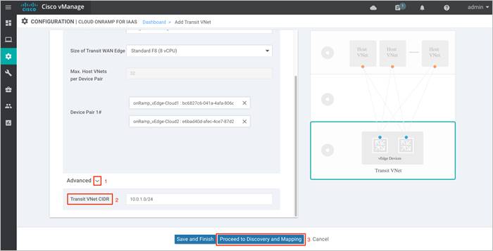
Step 3. Within the Cisco Cloud onRamp workflow, you specify an IPv4 CIDR block range when creating the transit VNet. This IPv4 CIDR range you configure is automatically sub-netted to create the necessary subnets for the network interfaces associated with the WAN Edge devices deployed in the Transit VNet.
The suggested CIDR is 10.0.0.0/16 for our new Transit VNet. Try to avoid using up an entire address space and divide the network in smaller chucks.
Select the Advanced tab, to enter the Transit VNet CIDR. This is a Classless Interdomain Routing value, which in our case is defined as 10.0.1.0/24.
Next, click Proceed to Discovery and Mapping to map host VNets to the transit VNet.
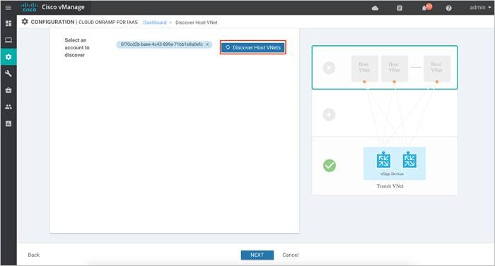
Procedure 3: Discover Host VNet
Host VNets part of the same Account ID or Subscription ID can be discovered and later mapped to the transit VNet.
Step 1. Click on the drop-down menu on the tab next to Select an account to discover. The drop down lists out the Subscription ID.
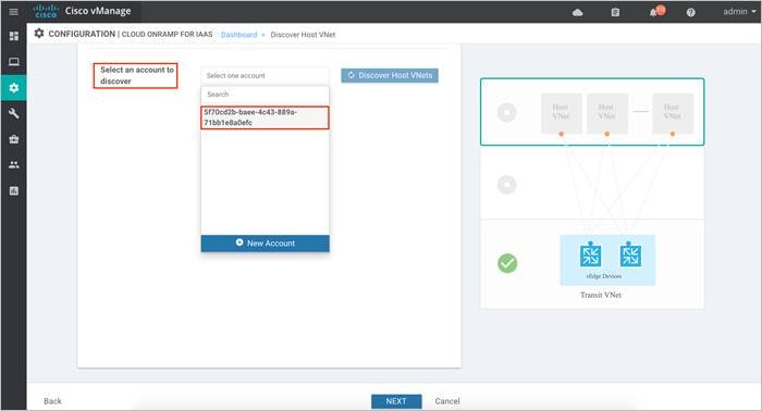
Step 2. Once the subscription ID is selected, click Discover Host VNets.
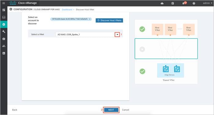
Step 3. Click on the drop-down arrow, to Select a host VNet. With this step, discovery of Host VNet is complete.
Click Next to map the selected host VNet to the transit VNet.
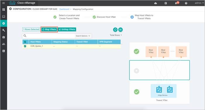
Procedure 4: Map Host VNets to Transit VNets
Each discovered Host VNet is mapped to the transit VNet. During this mapping process, Cloud onRamp for IaaS automatically provisions a Virtual Network Gateway in the host VNet which is associated to the VNet’s gateway subnet. The Virtual Network Gateway contains two public IP addresses for site-to-site connection, private IP addresses and a BGP ASN number for BGP peering. While public IP addresses are automatically added by Azure, the IPv4 CIDR address block for the private IP address is decided by the user during the host VNet to transit VNet mapping process.
Step 1. Click on Map VNets to map the discovered Host VNet to the Transit VNet COR_TransitVNet.
| Technical Tip |
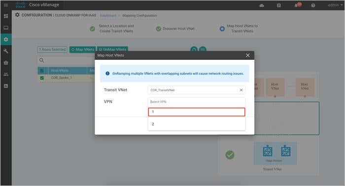
| If you try to click Save and Complete without mapping host VNet and transit VNet, an error message will pop-up - “Please create mapping in order to proceed”. |
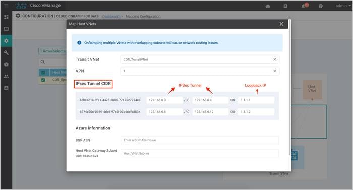
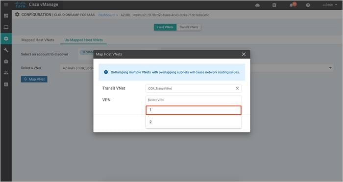
Step 2. A pop-up screen appears that lets you associate the mapping to a service-side VPN. Click on the drop-down menu and choose a VPN.
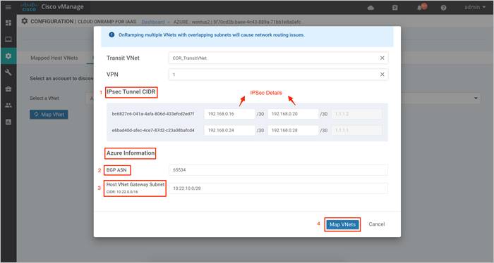
Step 3. On selecting a VPN, you will be navigated over to the following screen. Here, you define the IPsec site-to-site tunnel IP addresses under the IPsec Tunnel CIDR and the Loopback IP addresses.
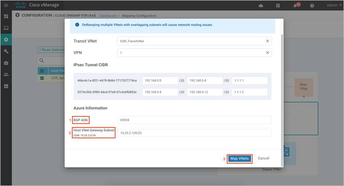
Step 4. The BGP ASN is used to build BGP sessions between the Host VNet and the Transit VNet. Under Azure Information, enter a BGP ASN. Also, based on the subnet you had defined in your Host VNet, define a Host VNet Gateway Subnet. Next, click on Map VNets.
Note, choose a subset of the subnet already assigned to your host VNet as the gateway subnet. To decide on the BGP ASN number refer to the Azure BGP guide.
The subnet defined within the Host VNet COR-Spoke-1 is 10.25.2.0/25. Therefore, the Host VNet Gateway Subnet defined here is 10.25.2.128/25. Two IP’s from this block will be used to establish BGP Peering with the WAN Edge device’s loopback IP over IPsec VPN tunnels.
Step 5. Finally, click Save and Complete to initiate the Cloud onRamp for IaaS workflow.
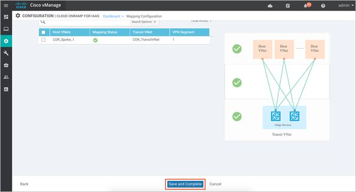
The configuration process takes about 15 to 20 minutes. Post completion, your Transit VNets will be provisioned on Azure with a pair of WAN Edge cloud routers configured based on the templates attached. The mapping of Host VNet and Transit VNet will also be complete.
Procedure 3: Use Case #1 – Full Connectivity
Optionally, you can associate additional host VNets with the transit VNet. For the this use case, both host VNets, COR-Spoke-1 and COR-Spoke-2 are mapped to same VPN on the transit VNet.
The main Cloud onRamp page has two tabs – Mapped Host VNets and Transit VNets.
Step 1. To map additional Host VNets, select the Mapped Host VNets Connections.
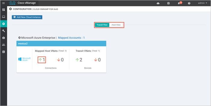
Step 2. You will be navigated to a page containing the Mapped Host VNets.
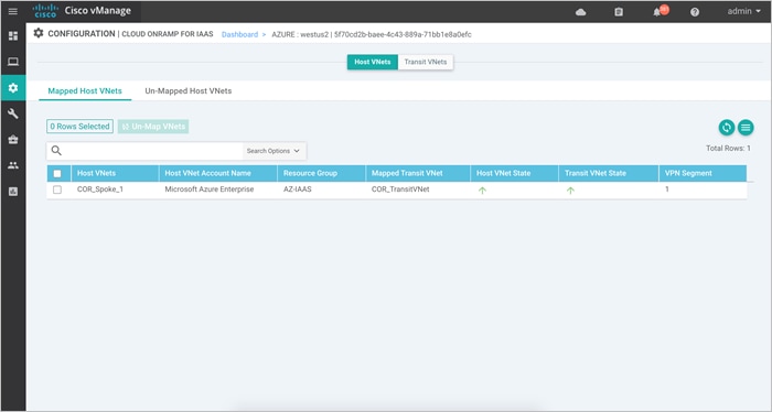
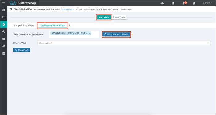
Step 3. Click on the Un-Mapped Host VNets tab. Within this Select an account to discover, choose your Subscription ID from the drop-down menu. Then click on Discover Host VNets. This will populate all the available VNets associated to the Subscription ID.
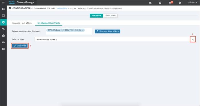
Step 4. Click on the drop-down menu located next to Select a VNet to choose the VNet you want to map. Once the VNet is selected, click Map VNet.
Step 5. Within pop-up screen, choose the VPN ID. The VPN ID is set to VPN 1.
Step 6. Define the IPsec tunnel CIDR details and BGP ASN used to build BGP sessions between the Host VNet and the Transit VNet. Also, define a Host VNet Gateway Subnet and click on Map VNets.
Note, mapping of Host VNet to Transit VNet can take up to 45 minutes.
Procedure 4: Use Case #2 – Segmentation
For the second use case, the first host VNet COR-Spoke-1 is mapped to VPN 1 on the transit VNet. The second and new host VNet COR-Spoke-2 is mapped to VPN 2.
The main Cloud onRamp page has two tabs, Mapped Host VNets and Transit VNets.
Step 1. To map additional Host VNets, select the Mapped Host VNets Connections.
Step 2. You will be navigated to a page containing the Mapped Host VNets.
Step 3. Click on the Un-Mapped Host VNets tab. Within Select an account to discover, choose your Subscription ID from the drop-down menu. Then click on Discover Host VNets. This will populate all the available VNets associated to the Subscription ID
Step 4. Click on the drop-down menu located next to Select a VNet to choose the VNet you want to map. Once the VNet is selected, click Map VNet.
Step 5. Within pop-up screen, choose the VPN ID. The VPN ID is set to VPN 2.
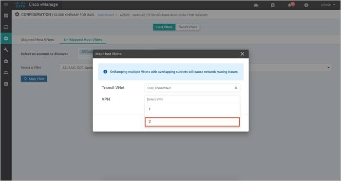
Step 6. Define the IPsec tunnel CIDR details, loopback IP and BGP ASN used to build BGP sessions between the Host VNet and the Transit VNet. Also, define a Host VNet Gateway Subnet and click on Map VNets.
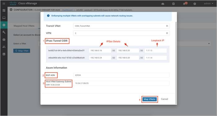
Step 7. The Cloud onRamp main page will appear similar to the figure below.
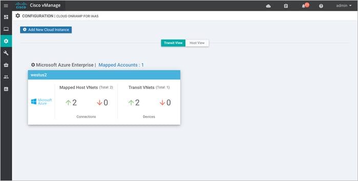
Operate - Cisco Cloud onRamp for IaaS Monitoring
Using the vManage GUI, you can monitor, troubleshoot, and manage the Cisco SD-WAN Cloud onRamp for IaaS using Azure deployment. The 3 main ways to troubleshoot the deployment are as follows:
vManage Cloud onRamp for IaaS Dashboard: From the vManage Cloud onRamp for IaaS dashboard you can monitor the connectivity state of each host VNet, the state of the transit VNet, and detailed traffic statistics for IPsec VPN connections between the transit VNet and the host VNets.
vManage Monitor Dashboard: From the vManage Monitor dashboard, you can view and gather error logs and interface details for the WAN Edge cloud routers deployed in the transit VNet
vManage SSH Server Dashboard: The vManage SSH server dashboard provides the option to manage and monitor the WAN Edge device via CLI.
At the end this section, you will find some of the common deployment mistakes.
Process 1: vManage Cisco Cloud onRamp for IaaS Dashboard
Procedure 1: View the connectivity state of each transit VNet
Step 1. Select the cloud icon at the top of the vManage GUI.
Step 2. From the drop-down menu select Cloud onRamp for IaaS.
Alternatively, to get to this page, you can select Configuration > Cloud onRamp for IaaS in the left-hand column of vManage.
You will be navigated to the following page.
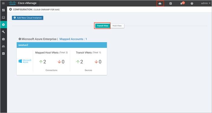
The aggregate number of host VNets which are reachable is indicated with a green "up" arrow under Mapped Host VNets. Likewise, the aggregate number of host VNets which are unreachable is indicated with a red "down" arrow. The color-coded "up" and "down" arrows indicate whether the IPsec VPN tunnels connecting the host VNets with the transit VNets are up or down.
The aggregate number of Cisco vEdge Cloud routers which are reachable is indicated with a green "up" arrow under Transit VNets. Likewise, the aggregate number of Cisco vEdge Cloud routers which are unreachable is indicated with a red "down" arrow. In the case of the transit VNet, the color-coded "up" and "down" arrows indicate whether the logical Cisco vEdge Cloud router is reachable or not. Generally, reachability indicates whether the Cisco vEdge Cloud router is running or not. Since there are two Cisco vEdge Cloud routers per transit VNet, the number of devices shown here should be twice the number of transit VNets.
Step 3. Click on Host View tab to gather additional details about the Azure account Name, hosted cloud region, VPN segmentation details per VNet, along with the reachability state of each transit VNet and host VNet.
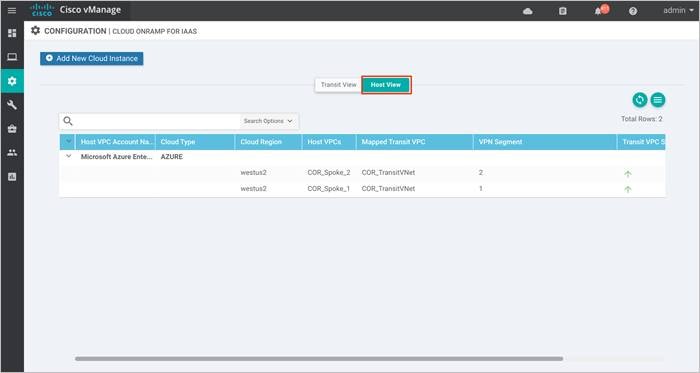
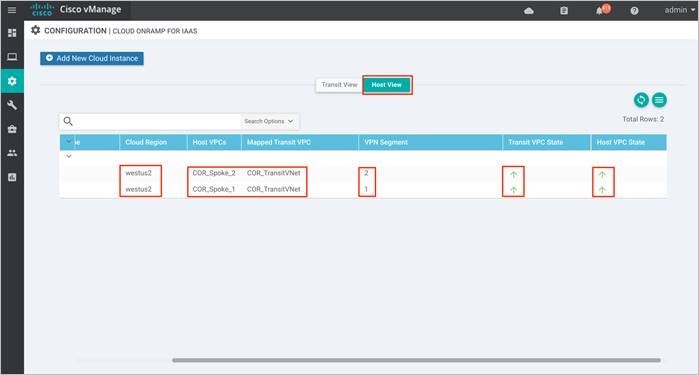
Step 4. When you click on the cloud instance, by default you are taken to a screen which displays the state of each host VNet within that cloud instance. An example is shown in the following figure.
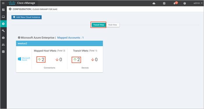
You can see specific details regarding whether individual host VNets are up or down, as well as their associated transit VNet. You can also see which service VNet the host VNet is mapped to at the transit VNet.
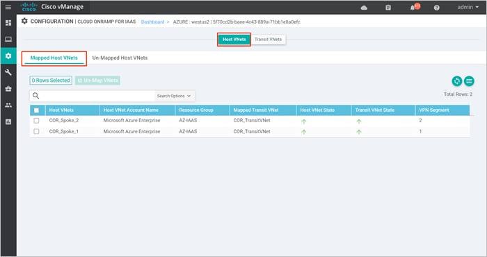
Step 5. Click on the Transit VNets tab to view the details of each transit VNet within the cloud instance.
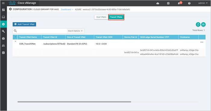
| Technical Tip |
| You can re-arrange the columns by dragging-and-dropping them so that the columns with the most relevant information come first, as shown in the figure above. The state of each of the Cisco vEdge Cloud routers within each transit VNet is displayed with a green "up" arrow or a red "down" arrow.
|
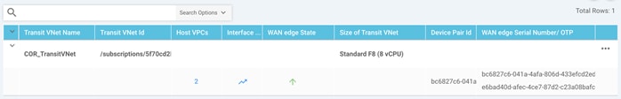
Step 6. Click on under Host VPCs (VNets) column to view the state of the host VNets.
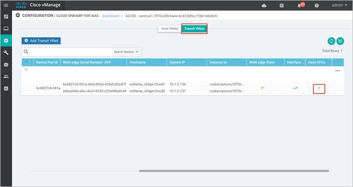
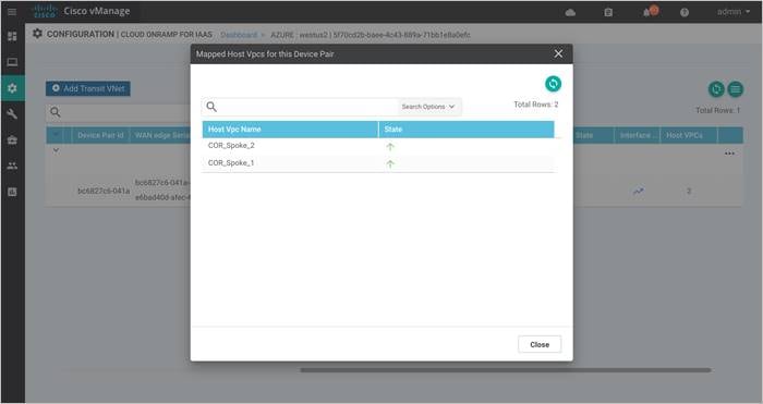
Procedure 2: View detailed traffic statistics for the IPsec VPN connections between the transit VNet and each host VNet
Although the more detailed information discussed in the previous procedure is useful in determining if a given Cisco vEdge Cloud router is up or down, it doesn't provide any information regarding the traffic between the transit VNet and each host VNet.
Step 1. Click on the graph icon for one of the Cisco WAN Edge Cloud routers under the Interface Stats column shown in the figure.
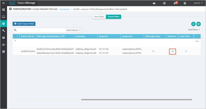
A pop-up screen displaying statistics for the IPsec VPN connections between the Cisco Cloud onRamp for IaaS transit VNet router and the host VNets is displayed.
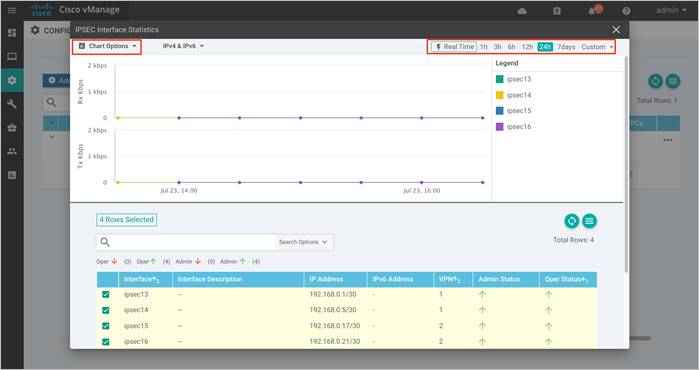
Step 2. From the drop-down menu under Chart Options, you can select the information displayed within the graph over each collection interval. The options are as follows:
Kbps - Traffic rate in kilobits per second for each collection interval
Packets - Packets seen over each collection interval
Octets - Bytes seen over each collection interval
Errors - Number of errors over each collection interval
Drops - Number of dropped packets over each collection interval
Pps - Rate in packets per second over each collection interval
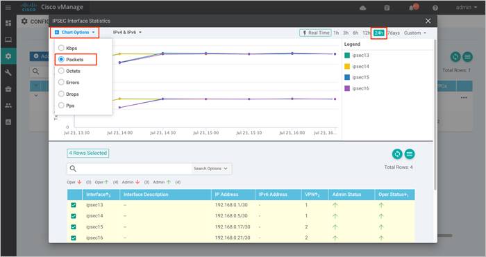
Step 3. You can also select one of the Legends to list details specific to that.
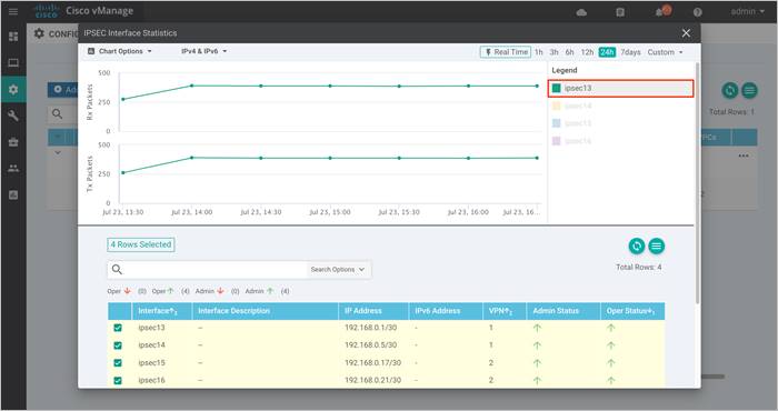
Step 4. The collection interval displayed within the graph varies based upon overall length of time displayed within the graph. This is selected in the upper right corner of the pop-up window. The time interval named Custom allows you to select a custom start date & time and end date & time. The collection interval depends on the start and end dates and times.
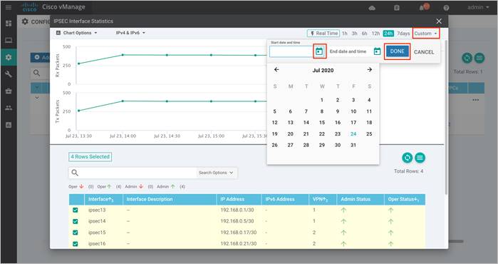
The collection interval is important because traffic rates may appear differently depending upon the interval over which they are averaged. Likewise, packet or byte counts will appear smaller over smaller collection intervals.
Statistics are displayed in both the transmit and receive direction - from the perspective of the Cisco WAN Edge Cloud router logical IPsec interfaces configured within the transit VPN. By default, statistics are displayed for all IPsec interfaces. You can remove an interface from the graph by un-selecting it in the panel below the graph.
Process 2: vManage Monitor Dashboard
Procedure 1: Monitor SD-WAN devices via Monitor tab
Step 1. To monitor both your controllers and WAN Edge devices within the Transit VNet, Navigate to Monitor > Events.
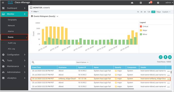
Step 2. To view more details for the error logs, you can also monitor your device by navigating to Monitor > Audit Log and click on the three dots (…) located on the right. Click on Audit Log Details to view the more details for the selected log message.
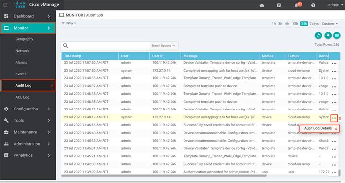
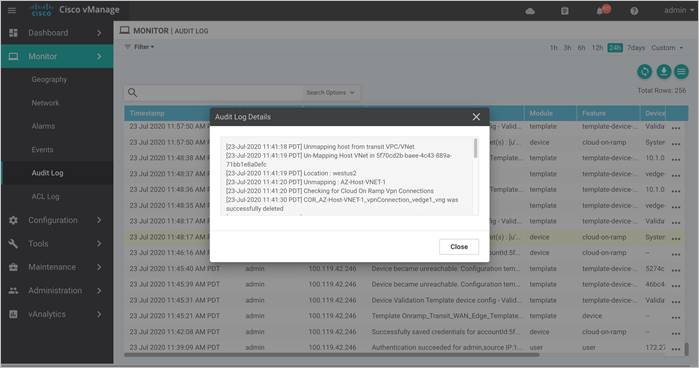
Step 3. To view interface and its associated traffic statistics, navigate to Monitor > Network, and select the device.
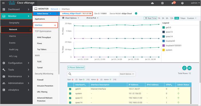
Step 4. You can alternatively view error logs specific to the WAN Edge device by clicking on the Events tab.
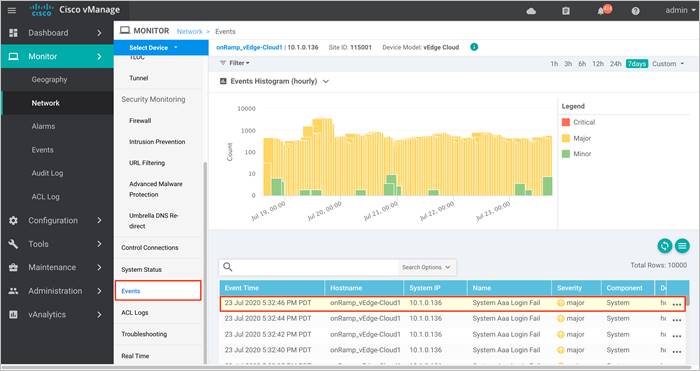
Process 3: vManage SSH Server Dashboard
Procedure 1: To monitor the WAN Edge routers hosted on transit VNet via vManage CLI, navigate to Tools > SSH and log into the one of the transit VNet vEdge routers.
Step 1. To view the BGP route details, from the CLI, issue the following commands “show bgp <neighbor/ routes/ summary>” and “show ip route bgp <detail>”.
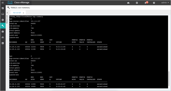
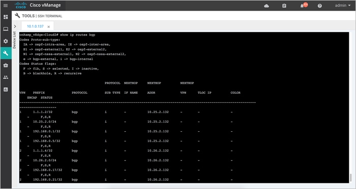
Step 2. To view IPsec active sessions via CLI issue the “show IPsec ike sessions | tab” command.
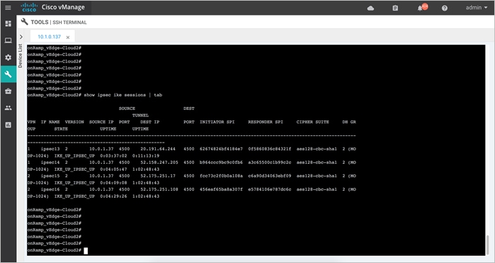
Some Common Deployment Mistakes
Note 1: Entering an Incorrect Host Gateway Subnet
During the mapping process, make sure to enter a Host Gateway subnet that is valid for the CIDR configured within the host VNet.
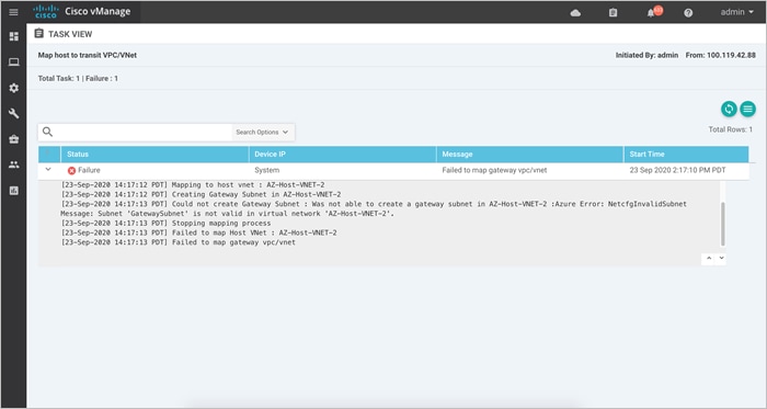
Note 2: Entering an Incorrect IPsec IP address CIDR Gateway Subnet
During the mapping process, make sure to enter an IPsec addresses that does not overlap with the host VNet subnet or address space.
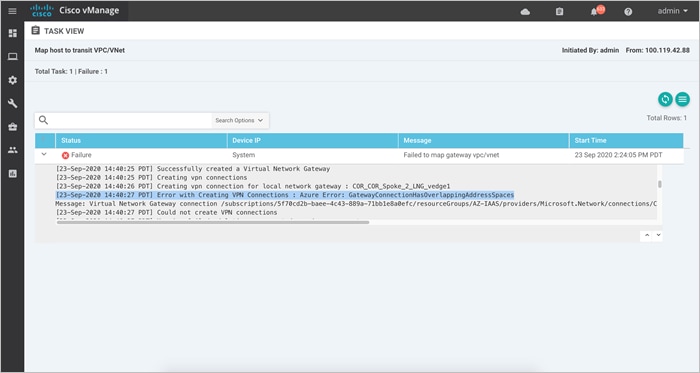
This guide is new and is not updated from a previous version.
Appendix B: Hardware and Software Used for Validation
This guide was validated using the following hardware and software.
Table 7. System Feature Template Settings
| Functional Area |
Product |
Software Version |
| Cloud |
Cisco vManage NMS |
19.2.2 |
| Cloud |
Cisco vBond Controller |
19.2.2 |
| Cloud |
Cisco vSmart Controller |
19.2.2 |
| Data center |
Cisco vEdge 5000 Series Routers |
19.2.2 |
| Branch office (cloud) |
Cisco vEdge |
19.2.2 |
| Transit VNet (cloud) |
Cisco vEdge |
19.1.0 |
Note: 19.1.0 was chosen to validate and deploy the cloud onRamp solution as it is the latest version available the vManage GUI running version 19.2.2/20.1 code.
Appendix C: Transit VNet Cisco WAN Edge Device and Feature Templates
This section includes the device and feature templates specific to the Cisco vEdge Cloud router attached to the Transit VNet device template. For templates specific to Data Center and Branch, refer to the Cisco SD-WAN End-to-End Deployment Guide.
Within this section, the configured lists, the main security policy template and its container template is listed.
Cisco vEdge feature templates
The following feature templates are common across Cisco vEdge and vEdge Cloud routers within the SD-WAN for this deployment guide. In other words, they apply not only to the Cisco vEdge Cloud routers within the transit VNet, but also to other physical and/or logical Cisco vEdge routers within the branch locations.
| Technical Tip |
| The configuration of the physical and/or logical Cisco SD-WAN Edge routers within the branch locations are not discussed within this deployment guide. |
vEdge System feature template
Devices: All Cisco vEdge
Template: Basic Information / System
Template Name: vEdge_System_Template
Description: vEdge System Template
Table 8. vEdge System feature template settings
| Section |
Parameter |
Type |
Variable/Value |
| Basic Configuration |
Site ID |
Device Specific |
system_site_id |
|
|
System IP |
Device Specific |
system_system_ip |
|
|
Hostname |
Device Specific |
system_host_name |
|
|
Device Groups |
Device Specific |
system_device_groups |
| GPS |
Latitude |
Device Specific |
system_latitude |
|
|
Longitude |
Device Specific |
system_longitude |
| Advanced |
Port Hopping |
Device Specific |
system_port_hop |
|
|
Port Offset |
Device Specific |
system_port_offset |
|
|
track-default-gateway |
Global |
Disable |
vEdge NTP feature template
Devices: All Cisco vEdge
Template: Basic Information / NTP
Template Name: vEdge_NTP_Template
Description: vEdge NTP Template
Table 9. vEdge NTP feature template settings
| Section |
Parameter |
Type |
Variable/Value |
| Server |
Hostname/IP Address |
Global |
time.nist.gov |
vEdge AAA feature template
Devices: All Cisco vEdge
Template: Basic Information / AAA
Template Name: vEdge_AAA_Template
Description: vEdge AAA Template
Table 10. vEdge AAA feature template settings
| Section |
Parameter |
Type |
Variable/Value |
| Authentication |
Authentication Order |
Drop-down |
local |
| Local |
Password |
Global |
<your admin password> |
vEdge BFD feature template
Devices: vEdge Cloud
Template: Basic Information / BFD_Template
Template Name: vEdge_Azure_Transit_BFD_Template
Description: vEdge BFD Template for Azure Transit VNet vEdge Cloud Routers
Table 11. vEdge BFD feature template settings
| Section |
Parameter |
Type |
Variable/Value |
| Basic Configuration |
Poll Interval |
Global |
120000 |
| Color (Biz Internet) |
Color |
Drop-down |
Biz Internet |
| Hello Interval (milliseconds) |
Device Specific |
biz_internet_bfd_hello_interval |
|
| Path MTU |
Global |
Off |
vEdge OMP feature template
Devices: All Cisco vEdge
Template: Basic Information / OMP
Template Name: vEdge_OMP_Template
Description: vEdge OMP Template
Table 12. vEdge OMP feature template settings
| Section |
Parameter |
Type |
Variable/Value |
| Basic configuration |
Number of Paths Advertised per Prefix |
Global |
16 |
| ECMP Limit |
Global |
16 |
|
| Advertise |
Connected |
Global |
Off |
| Static |
Global |
Off |
vEdge Security feature template
Devices: All Cisco vEdge
Template: Basic Information / Security
Template Name: vEdge_Security_Template
Description: vEdge Security Template
Table 13. vEdge Security feature template settings
| Section |
Parameter |
Type |
Variable/Value |
| Basic configuration |
Replay window |
Global / drop-down |
4096 |
vEdge VPN 0 feature template
Devices: vEdge Cloud
Template: VPN / VPN
Template Name: vEdge_Azure_Transit_VPN0_Template
Description: vEdge VPN0 Transport Template for Azure Transit VNet vEdge Cloud Routers
Table 14. vEdge VPN0 feature template settings
| Section |
Parameter |
Type |
Variable/Value |
| Basic Configuration |
VPN |
Global |
0 |
|
|
Name |
Global |
Transport VPN |
vEdge VPN 0 Interface Ethernet feature template
Devices: vEdge Cloud
Template: VPN / VPN Interface Ethernet
Template Name: vEdge_Azure_Transit_VPN0_Interface
Description: vEdge VPN 0 Transport Interface for Azure Transit VNet vEdge Cloud Routers
Table 15. vEdge VPN0 Interface Ethernet feature template settings (Internet)
| Section |
Parameter |
Type |
Variable/Value |
| Basic Configuration |
Shutdown |
Device Specific |
vpn0_inet_int_shutdown |
|
|
Interface Name |
Device Specific |
vpn0_inet_int_gex|x |
|
|
Description |
Global |
Internet Interface |
| IPv4 Configuration |
IPv4 Address |
Radio Button |
Dynamic |
|
|
Bandwidth Upstream |
Device Specific |
vpn0_inet_int_bandwidth_up |
|
|
Bandwidth Downstream |
Device Specific |
vpn0_inet_int_bandwidth_down |
| Tunnel |
Tunnel Interface |
Global |
On |
|
|
Color |
Global |
biz-internet |
|
|
Allow Service>NTP |
Global |
On |
| Tunnel>Advanced Options>Encapsulation |
IPsec Preference |
Device Specific |
vpn0_inet_tunnel_IPsec_preference |
| Advanced |
TCP MSS |
Global |
1350 |
|
|
Clear-Don’t-Fragment |
Global |
On |
vEdge VPN 512 feature template
Devices: vEdge Cloud
Template: VPN / VPN
Template Name: vEdge_Azure_Transit_VPN512_Template
Description: vEdge VPN 512 Out-of-Band Management for Azure Transit VNet vEdge Cloud Routers
Table 16. vEdge VPN512 feature template settings
| Section |
Parameter |
Type |
Variable/Value |
| Basic Configuration |
VPN |
Global |
512 |
|
|
Name |
Global |
Management VPN |
vEdge VPN 512 Interface Ethernet feature template
Devices: vEdge Cloud
Template: VPN / VPN Interface Ethernet
Template Name: vEdge_Azure_Transit_VPN512_Interface
Description: vEdge VPN 512 Management Interface for Azure Transit vEdge Cloud Routers
Table 17. vEdge VPN512 Interface Ethernet feature template settings
| Section |
Parameter |
Type |
Variable/Value |
| Basic Configuration |
Shutdown |
Global |
No |
|
|
Interface Name |
Device Specific |
vpn512_mgmt_int |
|
|
Description |
Global |
Management Interface |
| IPv4 Configuration |
IPv4 Address |
Radio Button |
Dynamic |
vEdge VPN 1 feature template
Devices: vEdge Cloud
Template: VPN / VPN
Template Name: vEdge_Azure_Transit_VPN1_Template
Description: vEdge VPN1 Service Template for Azure Transit VNet vEdge Cloud Routers
Table 18. vEdge VPN1 feature template settings
| Section |
Parameter |
Type |
Variable/Value |
| Basic Configuration |
VPN |
Global |
1 |
|
|
Name |
Global |
Service VPN 1 |
|
|
Enhance ECMP Keying |
Global |
On |
| Advertise OMP |
BGP (IPv4) |
Global |
On |
|
|
Connected (IPv4) |
Global |
On |
BGP routes are advertised within OMP for service VPN 1. Connected routes are also advertised within OMP so that the IP addresses of the Loopback0 interfaces, which are part of VPN 1, are visible across the network.
vEdge VPN 1 Interface Ethernet Loopback0
Devices: All Cisco vEdge
Template: VPN / VPN Interface Ethernet
Template Name: vEdge_VPN1_Lo0
Description: vEdge Service VPN 1 Interface Loopback 0
Table 19. vEdge VPN 1 Interface Ethernet Loopback0 feature template settings
| Section |
Parameter |
Type |
Variable/Value |
| Basic Configuration |
Shutdown |
Global |
No |
|
|
Interface Name |
Global |
loopback0 |
| IPv4 Configuration |
IPv4 Address |
Radio Button |
Static |
|
|
IPv4 Address |
Device Specific |
vpn1_lo0_int_ip_addr|maskbits |
vEdge VPN 2 feature template
Devices: vEdge Cloud
Template: VPN / VPN
Template Name: vEdge_Azure_Transit_VPN2_Template
Description: vEdge VPN2 Service Template for Azure Transit VNet vEdge Cloud Routers
Table 20. VPN2 feature template settings
| Section |
Parameter |
Type |
Variable/Value |
| Basic Configuration |
VPN |
Global |
2 |
|
|
Name |
Global |
Service VPN 2 |
|
|
Enhance ECMP Keying |
Global |
On |
| Advertise OMP |
BGP (IPv4) |
Global |
On |
BGP routes are advertised within OMP for service VPN 2.
Transit VNet Device Template
Azure Transit VNet vEdge Device Template
The following table summarizes the device template for the Cisco vEdge Cloud routers deployed within the Azure transit VNet.
Device Model: vEdge Cloud
Template Name: onRamp_Transit_WAN_Edge_Template
Description: vEdge Template for Cloud onRamp for IaaS Routers in a Transit VNet
Table 21. Transit VNet device template: Onramp_Transit_WAN_edge_Template
| Template Type |
Template Sub-Type |
Template Name |
| System |
|
vEdge_System_Template |
|
|
NTP |
vEdge_NTP_Template |
|
|
AAA |
vEdge_AAA_Template |
| BFD |
|
vEdge_Azure_Transit_BFD_Template |
| OMP |
|
vEdge_OMP_Template |
| Security |
|
vEdge_Security_Template |
| VPN0 |
|
vEdge_Azure_Transit_VPN0_Template |
|
|
VPN Interface |
vEdge_Azure_Transit_VPN0_Interface |
| VPN512 |
|
vEdge_Azure_Transit_VPN512_Template |
|
|
VPN Interface |
vEdge_Azure_Transit_VPN512_Interface |
| VPN1 |
|
vEdge_Azure_Transit_VPN1_Template |
|
|
VPN Interface |
vEdge_VPN1_Lo0 |
| VPN2 |
|
vEdge_Azure_Transit_VPN2_Template |
The following section lists out an example transit VNet configuration.
onRamp_vEdge-Cloud1
system
host-name onRamp_vEdge-Cloud1
gps-location latitude 37.3541
gps-location longitude -121.9552
device-groups Azure
system-ip 10.1.0.136
site-id 115001
port-offset 1
admin-tech-on-failure
no route-consistency-check
sp-organization-name "ENB-Solutions - 21615"
organization-name "ENB-Solutions - 21615"
no track-default-gateway
clock timezone America/Los_Angeles
vbond 52.156.128.118
aaa
auth-order local radius tacacs
usergroup basic
task system read write
task interface read write
!
usergroup netadmin
!
usergroup operator
task system read
task interface read
task policy read
task routing read
task security read
!
user admin
password $6$V8EKzg==$ulijOEP9FwPzfA3kwsTW6nRb9xxjDH38mp.ePVxVz17tNtLdJQdW58b9K
3eVQX7CIma3JD042IpjA5aWLWulv0
!
!
logging
disk
enable
!
!
ntp
server time.nist.gov
version 4
exit
!
!
bfd color biz-internet
hello-interval 10000
multiplier 3
!
bfd app-route poll-interval 120000
omp
no shutdown
send-path-limit 16
ecmp-limit 16
graceful-restart
!
security
IPsec
replay-window 4096
authentication-type sha1-hmac ah-sha1-hmac
!
!
vpn 0
name "Transport VPN"
interface ge0/0
description "Internet Interface"
ip dhcp-client
tunnel-interface
encapsulation IPsec
color biz-internet
allow-service all
allow-service bgp
allow-service dhcp
allow-service dns
allow-service icmp
allow-service sshd
no allow-service netconf
allow-service ntp
no allow-service ospf
no allow-service stun
allow-service https
!
clear-dont-fragment
tcp-mss-adjust 1350
no shutdown
bandwidth-upstream 1000000
bandwidth-downstream 1000000
!
ip route 0.0.0.0/0 10.0.1.33
ip route 52.156.128.118/32 10.0.1.33
ip route 52.233.80.195/32 10.0.1.33
ip route 52.233.90.51/32 10.0.1.33
ip route 173.36.197.111/32 10.0.1.33
ip route 173.36.197.112/32 10.0.1.33
!
vpn 1
name "Service VPN 1"
ecmp-hash-key layer4
router
bgp 64600
timers
holdtime 30
!
address-family ipv4-unicast
network 0.0.0.0/0
!
neighbor 10.25.2.132
no shutdown
remote-as 65534
update-source loopback1000001
ebgp-multihop 2
!
neighbor 10.25.2.133
no shutdown
remote-as 65534
update-source loopback1000001
ebgp-multihop 2
!
!
!
interface IPsec21
ip address 192.168.0.1/30
tunnel-source 10.0.1.36
tunnel-destination 52.250.11.112
ike
version 2
rekey 28800
cipher-suite aes128-cbc-sha1
group 2
authentication-type
pre-shared-key
pre-shared-secret "$8$UalW0IM0z/ulqbs6Zrt2IHEdSd+tE2CElhfW4UItGlou0+k9TJj4nb
wb/Q4pmuybHVwbDc27\nFBH6cswinsQowQ=="
!
!
!
IPsec
rekey 3600
replay-window 512
cipher-suite aes256-cbc-sha1
perfect-forward-secrecy none
!
no shutdown
!
interface IPsec22
ip address 192.168.0.5/30
tunnel-source 10.0.1.36
tunnel-destination 52.250.11.161
ike
version 2
rekey 28800
cipher-suite aes128-cbc-sha1
group 2
authentication-type
pre-shared-key
pre-shared-secret "$8$Vj6+q7rWu16lNdWdRCnU/xPPQ0QvSume53ZT5Lvz0th6H8XbhW9TlP
TGBZU/7p4TVbk3+C93\n9WAphM6CxvVOcQ=="
!
!
!
IPsec
rekey 3600
replay-window 512
cipher-suite aes256-cbc-sha1
perfect-forward-secrecy none
!
no shutdown
!
interface loopback0
ip address 10.1.0.136/32
no shutdown
!
interface loopback1000001
ip address 2.2.2.3/32
no shutdown
!
ip route 0.0.0.0/0 null0
ip route 10.25.2.132/32 192.168.0.2
ip route 10.25.2.133/32 192.168.0.6
omp
advertise bgp
advertise connected
!
!
vpn 2
name "Service VPN 2"
ecmp-hash-key layer4
router
bgp 64600
timers
holdtime 30
!
address-family ipv4-unicast
network 0.0.0.0/0
!
neighbor 10.26.2.132
no shutdown
remote-as 65534
update-source loopback1000002
ebgp-multihop 2
!
neighbor 10.26.2.133
no shutdown
remote-as 65534
update-source loopback1000002
ebgp-multihop 2
!
!
!
interface IPsec19
ip address 192.168.0.17/30
tunnel-source 10.0.1.36
tunnel-destination 51.143.15.221
ike
version 2
rekey 28800
cipher-suite aes128-cbc-sha1
group 2
authentication-type
pre-shared-key
pre-shared-secret "$8$a1e0Ma1RZ4mz1vGsuW/j5FJCvWxoOKjlMuFsW48sXMgTRWGLyxZd/0
YBQTukcJRi4lYiF1Rh\nbA1iCUFJmdeEGg=="
!
!
!
IPsec
rekey 3600
replay-window 512
cipher-suite aes256-cbc-sha1
perfect-forward-secrecy none
!
no shutdown
!
interface IPsec20
ip address 192.168.0.21/30
tunnel-source 10.0.1.36
tunnel-destination 52.250.119.9
ike
version 2
rekey 28800
cipher-suite aes128-cbc-sha1
group 2
authentication-type
pre-shared-key
pre-shared-secret "$8$ttuF8nHUq2Ne3UDTTBaUvsuAONJTmIEr+WcIYprYBkrBMq/bsFKwi0
L7fZnUfinHFReHZaeN\nX9s8iavTJyr9zg=="
!
!
!
IPsec
rekey 3600
replay-window 512
cipher-suite aes256-cbc-sha1
perfect-forward-secrecy none
!
no shutdown
!
interface loopback1000002
ip address 1.1.1.4/32
no shutdown
!
ip route 0.0.0.0/0 null0
ip route 10.26.2.132/32 192.168.0.18
ip route 10.26.2.133/32 192.168.0.22
omp
advertise bgp
advertise connected
!
!
vpn 512
name "Management VPN"
interface eth0
description "Management Interface"
ip dhcp-client
no shutdown
!
!
onRamp_vEdge-Cloud2
system
host-name onRamp_vEdge-Cloud2
gps-location latitude 37.3541
gps-location longitude -121.9552
device-groups Azure
system-ip 10.1.0.137
site-id 115001
port-offset 1
admin-tech-on-failure
no route-consistency-check
sp-organization-name "ENB-Solutions - 21615"
organization-name "ENB-Solutions - 21615"
no track-default-gateway
clock timezone America/Los_Angeles
vbond 52.156.128.118
aaa
auth-order local radius tacacs
usergroup basic
task system read write
task interface read write
!
usergroup netadmin
!
usergroup operator
task system read
task interface read
task policy read
task routing read
task security read
!
user admin
password $6$V8EKzg==$ulijOEP9FwPzfA3kwsTW6nRb9xxjDH38mp.ePVxVz17tNtLdJQdW58b9K3eVQX7CIma3JD042IpjA5aWLWulv0
!
!
logging
disk
enable
!
!
ntp
server time.nist.gov
version 4
exit
!
!
bfd color biz-internet
hello-interval 10000
no pmtu-discovery
!
bfd app-route poll-interval 120000
omp
no shutdown
send-path-limit 16
ecmp-limit 16
graceful-restart
!
security
IPsec
replay-window 4096
authentication-type sha1-hmac ah-sha1-hmac
!
!
vpn 0
name "Transport VPN"
interface ge0/0
description "Internet Interface"
ip dhcp-client
tunnel-interface
encapsulation IPsec
color biz-internet
allow-service all
allow-service bgp
allow-service dhcp
allow-service dns
allow-service icmp
allow-service sshd
no allow-service netconf
allow-service ntp
no allow-service ospf
no allow-service stun
allow-service https
!
clear-dont-fragment
tcp-mss-adjust 1350
no shutdown
bandwidth-upstream 1000000
bandwidth-downstream 1000000
!
ip route 0.0.0.0/0 10.0.1.33
ip route 52.156.128.118/32 10.0.1.33
ip route 52.233.80.195/32 10.0.1.33
ip route 52.233.90.51/32 10.0.1.33
ip route 173.36.197.111/32 10.0.1.33
ip route 173.36.197.112/32 10.0.1.33
!
vpn 1
name "Service VPN 1"
ecmp-hash-key layer4
router
bgp 64600
timers
holdtime 30
!
address-family ipv4-unicast
network 0.0.0.0/0
!
neighbor 10.25.2.132
no shutdown
remote-as 65534
update-source loopback1000001
ebgp-multihop 2
!
neighbor 10.25.2.133
no shutdown
remote-as 65534
update-source loopback1000001
ebgp-multihop 2
!
!
!
interface IPsec13
ip address 192.168.0.9/30
tunnel-source 10.0.1.37
tunnel-destination 20.191.64.244
ike
version 2
rekey 28800
cipher-suite aes128-cbc-sha1
group 2
authentication-type
pre-shared-key
pre-shared-secret "$8$kzM/CIMpHYv0z8t51pNILnUDUNUUUqrKzra3PbO1sGUrIm+lwmaijpxknx+G7lsLsfx1X9pW\nNrYhMlhRMz4D2w=="
!
!
!
IPsec
rekey 3600
replay-window 512
cipher-suite aes256-cbc-sha1
perfect-forward-secrecy none
!
no shutdown
!
interface IPsec14
ip address 192.168.0.13/30
tunnel-source 10.0.1.37
tunnel-destination 52.158.247.205
ike
version 2
rekey 28800
cipher-suite aes128-cbc-sha1
group 2
authentication-type
pre-shared-key
pre-shared-secret "$8$jhSJlxN2vlwPwkaGoLXmkMnO1CuxwJLd1XqpBPvooaKtA9jUOJ2XUglZq/uOrFPlFU/fWKae\nmGZCE53dpN58Yg=="
!
!
!
IPsec
rekey 3600
replay-window 512
cipher-suite aes256-cbc-sha1
perfect-forward-secrecy none
!
no shutdown
!
interface loopback0
ip address 10.1.0.137/32
no shutdown
!
interface loopback1000001
ip address 1.1.1.1/32
no shutdown
!
ip route 0.0.0.0/0 null0
ip route 10.25.2.132/32 192.168.0.10
ip route 10.25.2.133/32 192.168.0.14
omp
advertise bgp
advertise connected
!
!
vpn 2
name "Service VPN 2"
ecmp-hash-key layer4
router
bgp 64600
timers
holdtime 30
!
address-family ipv4-unicast
network 0.0.0.0/0
!
neighbor 10.26.2.132
no shutdown
remote-as 65534
update-source loopback1000002
ebgp-multihop 2
!
neighbor 10.26.2.133
no shutdown
remote-as 65534
update-source loopback1000002
ebgp-multihop 2
!
!
!
interface IPsec15
ip address 192.168.0.25/30
tunnel-source 10.0.1.37
tunnel-destination 52.175.251.17
ike
version 2
rekey 28800
cipher-suite aes128-cbc-sha1
group 2
authentication-type
pre-shared-key
pre-shared-secret "$8$j8wRp13y9AdVBkQsJH0L5SOO/+b9v0OIqWAp/Bdy1zQ2ybYlDP1OcyLptjKzv9DYg0FmEqO1\nuezJ24xNElNe/Q=="
!
!
!
IPsec
rekey 3600
replay-window 512
cipher-suite aes256-cbc-sha1
perfect-forward-secrecy none
!
no shutdown
!
interface IPsec16
ip address 192.168.0.29/30
tunnel-source 10.0.1.37
tunnel-destination 52.175.251.108
ike
version 2
rekey 28800
cipher-suite aes128-cbc-sha1
group 2
authentication-type
pre-shared-key
pre-shared-secret "$8$elffP+KjzYpn3j0G/Ckg8JhPKDcbBUclPpJNJsnc4z4G8ztgEB/Q9PhsK+TnOvU8CjDmcoz/\nsuXo7oXwS6jaeA=="
!
!
!
IPsec
rekey 3600
replay-window 512
cipher-suite aes256-cbc-sha1
perfect-forward-secrecy none
!
no shutdown
!
interface loopback1000002
ip address 1.1.1.3/32
no shutdown
!
ip route 0.0.0.0/0 null0
ip route 10.26.2.132/32 192.168.0.26
ip route 10.26.2.133/32 192.168.0.30
omp
advertise bgp
advertise connected
!
!
vpn 512
name "Management VPN"
interface eth0
description "Management Interface"
ip dhcp-client
no shutdown
!
!
VPN Virtual Private Network
NAT Network Address Translation
LAN Local Area Network
WAN Wide Area Network
DNS Domain Name Server
VNET Virtual Network
VPN Virtual Private Network
GW Gateway
NSG Network Security Group
VM Virtual Machine
LNG Local Network Gateway
For comments and suggestions about this guide and related guides, join the discussion on Cisco Community at https://cs.co/en-cvds.