Deploying Shared-Border in VXLAN Multi-Site with Cisco NDFC
Available Languages
Bias-Free Language
The documentation set for this product strives to use bias-free language. For the purposes of this documentation set, bias-free is defined as language that does not imply discrimination based on age, disability, gender, racial identity, ethnic identity, sexual orientation, socioeconomic status, and intersectionality. Exceptions may be present in the documentation due to language that is hardcoded in the user interfaces of the product software, language used based on RFP documentation, or language that is used by a referenced third-party product. Learn more about how Cisco is using Inclusive Language.
- US/Canada 800-553-2447
- Worldwide Support Phone Numbers
- All Tools
 Feedback
 Feedback
The Shared-Border is a common external connectivity point for multiple VXLAN BGP EVPN fabrics interconnected with EVPN Multi-Site architecture. Unlike the BGW (Border Gateway), the Shared-Border does not have any specific requirement other than “normal” VXLAN EVPN support; it is solely a Shared-Border node topologically outside one or more sites. The Shared-Border operates like a traditional VTEP, but unlike the Site-Internal VTEPs, the Shared-Border is a Site-External VTEP. In the case of external connectivity, the Shared-Border operates solely in Layer 3 mode; hence, no BUM replication between the BGW nodes of the VXLAN EVPN fabrics and Shared-Border nodes is necessary. We must configure the VXLAN BGP EVPN VTEP on the Shared-border, and it must be present in a different autonomous system than the one that includes the BGWs.
Depending on hardware and software capabilities, the Shared-Border can enable external connectivity with various Layer 3 technologies. Some examples are Cisco Nexus 9000 Series switches (VRF Lite and MPLS L3VPN), Cisco Nexus 7000 Series Switches (VRF Lite, MPLS L3VPN, and LISP), Cisco ASR 9000 Series Aggregation Services Routers (VRF Lite and MPLS L3VPN), and Cisco ASR 1000 Series routers (VRF Lite and MPLS L3VPN).
Shared-Border Use-Cases
Flexible integration in a scalable Multi-Site architecture
Today, large Enterprises and Service Providers deploy scalable data centers with upwards of 1000 racks within the data center's physical location. To simplify operations and limit the fault domain, the data center should logically be segmented into smaller fabrics, able to extend any VRF and network anywhere within the data center.
For example, assume that we need to design a large VXLAN EVPN data center in New York with 500 switches while considering future growth, availability, and scalability. Today, NX-OS supports 512 VTEPs in a single fabric. A VTEP is a Nexus 9000 switch acting as a VXLAN Tunnel End Point to encapsulate Layer 2 and Layer 3 VXLAN Overlay traffic over a generic IP-routed fabric.
One way to accomplish this is to design a large spine-leaf VXLAN fabric with 500 switches. However, this approach can introduce challenges such as a common underlay plane, common overlay plane, faith sharing, single point of change, admin, and fault domain.
Instead, another approach is to implement VXLAN EVPN Multi-Site to address all the shortcomings of a single fabric option. Some of the key advantages of Multi-Site are the following:
1. Multiple underlay domains - Isolated
2. Multiple replicate domains for BUM - Interconnected and controlled
3. Multiple overlay domains - Interconnected and controlled
4. Multiple overlay control plane domains – Interconnected and controlled
5. Multiple VNI admin domains – Downstream VNI
6. Flexible Layer 2 and Layer 3 DCI services
7. VXLAN to IP handoff
8. Layer 4 to Layer 7 service insertion and redirection
9. Integration with legacy networks (vPC, FabricPath)
10. VXLAN Layer 3 extension to Public Cloud
Hence, splitting a single 500-switch fabric into smaller fabrics with a Multi-Site extension is strongly recommended. We can create five individual VXLAN EVPN fabrics with 100 switches or ten fabrics with 50 switches and interconnect them to extend any VRF and network anywhere between these fabrics. This approach allows us to deploy horizontal scale-out architecture while maintaining the overall VTEP scale and other attributes. But, in such a design, we still need to decide on the north-to-south ingress/egress point, service nodes perimeter point, and more.
For example, we need to address the following:
- Where do we connect the DMZ/perimeter firewall?
- Where do we connect Internet/WAN links?
- How can we optimize the traffic paths and minimize the hair pinning?
In this design approach, we can place a Shared-Border plane centrally as a deterministic point for any Layer 3 north-to-south or service insertion use cases. The Shared-Border belongs to an independent fabric serving as a common entry and exit point for a given data center.
Flexible Hardware and Software requirements
Shared-Border is independent of any VXLAN EVPN Multi-Site software or hardware requirements; it is solely a border leaf node. The Shared-Border is also independent of a BGW (Border Gateway) from a functionality and licensing point of view. The minimum licensing requirement for Shared-Border is Network Essentials.
Flexible IP Handoff options
Shared-Border can terminate and handoff VXLAN EVPN traffic to external networks using VRF Lite (VXLAN to Native IP/IPv6 and vice versa) or MPLS VPN (VXLAN to MPLS-LDP/MPLS-SR and vice versa). Hence, Shared-Border can be utilized in a two-box or a one-box handoff solution.
Note: The support for VPN handoff is dependent on the specific hardware and software versions.
Service Node Insertion and Redirection
Shared-Border can be implemented as a set of standalone VTEPs or as a pair of VTEPs that are part of a vPC domain (vPC with Peer-Link or vPC Fabric-Peering). Hence, it simplifies the interconnection with Layer 4 to Layer 7 service nodes. Typically, the Shared-Border operates in Layer 3 mode. But if there are specific DMZ use cases, such as applications having their default gateway on a firewall cluster and the cluster is connected to the Shared-Border, we can extend the Layer 2 VNI across VXLAN EVPN Multi-Site and Shared-Border fabrics.
Centralized VRF Route-Leaking
The Shared-Border approach allows network admins to implement a centralized route-leaking option to simplify configurations, operations, troubleshooting, security domains, and more. The individual VXLAN EVPN fabrics rely on the Shared-Border as the inter-VRF leaking point.
Shared-Border Design
Availability Zones and Regions
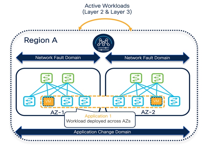
When describing data center deployment architectures, a geographical location is often referred to as a "site." At the same time, the term "site" may also refer to a specific VXLAN EVPN fabric part of a Multi-Site architecture, and this may lead to confusion because multiple fabrics may be deployed in a given "site" geographical location. Hence, it is helpful to introduce terms like "Availability Zone" and "Region" to differentiate deployment scenarios.
An Availability Zone (AZ) refers to a set of network components representing a specific infrastructure fault domain. For VXLAN EVPN deployments, an AZ corresponds to a fabric part of a particular NDFC MSD construct. The geographic placement of AZs depends on the use case; for scaling-out network designs, for example, it is possible to deploy multiple AZs in the same physical (and geographic) data center location.
A Region is a collection of one or more AZs representing a single change and resource domain; a region typically includes AZs deployed in one or more geographic data center locations. In terms of a VXLAN EVPN deployment with NDFC, a Region represents a single fabric or multiple fabrics managed through a single NDFC controller (and hence part of the same NDFC MSD construct). So a controller's scope is that of managing all the data centers (or AZs) within the region.
Design Option 1
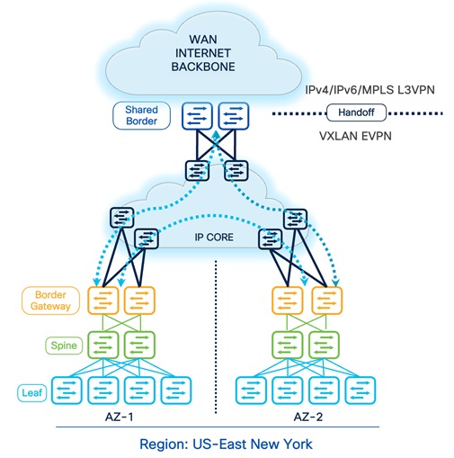
DCI- BGW to Cloud
The BGW to Cloud deployment model provides scalable design options within and across multiple sites. The Backbone/Cloud/IP-Core can be any routed service such as IP Layer 3 or MPLS-L3VPN network. The IP-Core is responsible for advertising and exchanging the loopback information between BGWs and the Shared-Border. In this approach, the BGWs in a given AZ peer full-mesh with the BGWs deployed in other AZs. The Shared-Border acts as an external VTEP and participates in EVPN overlay sessions with the BGWs. We must ensure that the Primary IP and Virtual IP (typically Lo0 for the EVPN control plane, and Lo1 and Lo100 for the VXLAN data plane) of all BGWs and Shared-Border are known to each other, and the MTU must accommodate VXLAN encapsulated traffic.
Connectivity Key:
![]() Multi-Site Underlay: eBGP IPv4 Unicast
Multi-Site Underlay: eBGP IPv4 Unicast
- Site-External DCI BUM: Ingress-Replication or Multicast supported. At this time, Cisco NDFC supports only Ingress-Replication.
- Site-Internal Fabric BUM: Ingress-Replication or Multicast supported independently at each site.
- The eBGP IPv4 Unicast is used to exchange the IP reachability across BGWs and Shared-Border. Furthermore, if Shared-Border is running as a Layer 3 only VTEP, the BUM functionality and L2VNI definition can be skipped on the Shared-Border device.
![]() Multi-Site Overlay: eBGP EVPN Overlay
Multi-Site Overlay: eBGP EVPN Overlay
- Full-Mesh BGP EVPN peering across all BGWs and Shared-Border.
Design Option 2
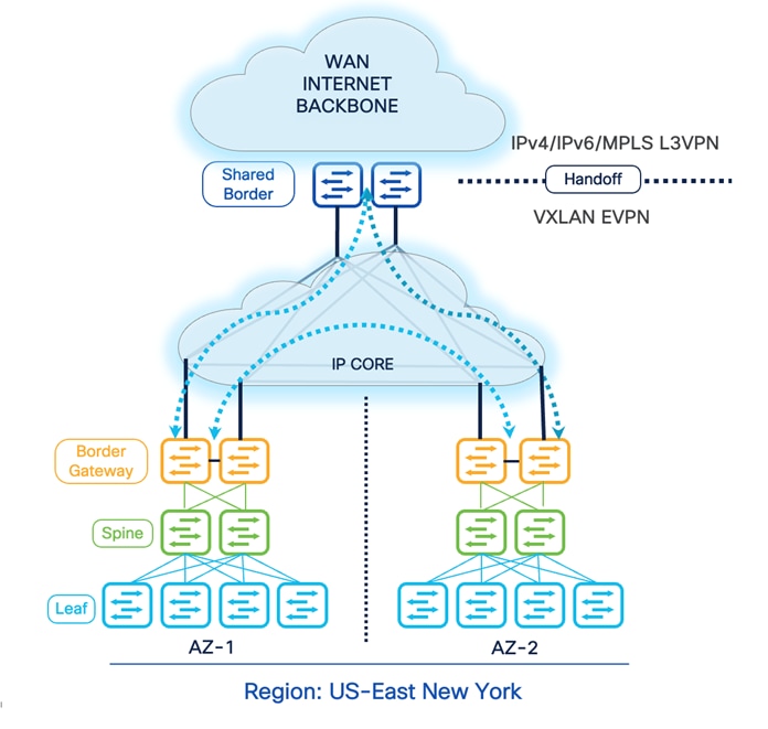
DCI- BGW Back-to-Back
Another option is to connect VXLAN EVPN AZs using the BGW Back-to-Back deployment model. In this approach, the BGWs and Shared-Border are directly connected. Hence, considering the cable availability, physical restrictions, geographic locations, and other dependencies, this model is limited and recommended for connecting a maximum of two sites. As a best practice design principle, connecting every BGW and Shared-Border is recommended. Still, due to certain restrictions, if this is not possible, the minimum topology for Back-to-Back is the square topology. The square connectivity mandates the deployment of a local Layer 3 connection between BGWs of a given site to ensure seamless and improved ECMP, BUM, data plane traffic, and failure scenarios.
Connectivity Key:
![]() Multi-Site Underlay: eBGP IPv4 Unicast
Multi-Site Underlay: eBGP IPv4 Unicast
- Site-External DCI BUM: Ingress-Replication or Multicast supported. At this time, Cisco NDFC supports only Ingress-Replication.
- Site-Internal Fabric BUM: Ingress-Replication or Multicast supported independently at each site.
- The eBGP IPv4 Unicast is used to exchange the IP reachability across BGWs and Shared-Border. Furthermore, if Shared-Border is running as a Layer 3 only VTEP, the BUM functionality and L2VNI definition can be skipped on the Shared-Border device.
![]() Multi-Site Overlay: eBGP EVPN Overlay
Multi-Site Overlay: eBGP EVPN Overlay
- Full-Mesh BGP EVPN peering across all BGWs and Shared-Border.
Design Option 3
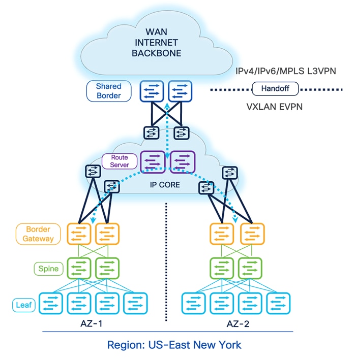
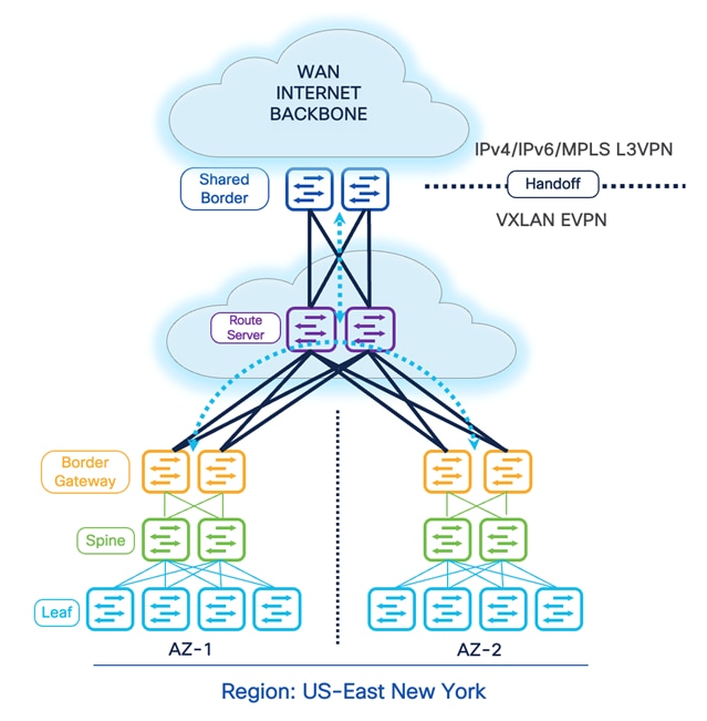
DCI- BGW to Centralized Route Server
The previous design options require us to implement a Full-Mesh configuration of EVPN sessions across all participating BGWs across all available sites. The EVPN Full-Mesh peering and adjacencies can significantly increase as we grow horizontally. The Full-Mesh option may introduce challenges from a physical cabling, configuration, management, and troubleshooting point of view. Therefore, for multiple VXLAN Sites, it is recommended that you leverage the BGP EVPN Route Server model. This model helps contain the overall connectivity, configurations, management, and more.
The Route Server model allows administrators to place a switch or router capable of running certain functionality and peer directly with the BGWs. It is essentially like a RR (Route Reflector) for eBGP EVPN sessions.Therefore, all the BGWs peer directly or indirectly with the Route Servers. The Route Server can be Nexus or Non-Nexus devices that comply with RFC 7947 and support EVPN AFI and BGP extensions, such as next-hop-unchanged, retain RTs, and RT rewrite functions.
Furthermore, the Route Server does not need to be on the data plane path. Therefore, we can place a set of devices acting as the Route Server in the backbone WAN and establish eBGP EVPN Multi-Hop peering with the BGWs. Another approach is to physically connect every BGW to the Route Server and establish the peering. Thus, depending on the overall physical and logical network connectivity, the Route Server may or may not be part of the data plane.
Connectivity Key:
![]() Multi-Site Underlay: eBGP IPv4 Unicast
Multi-Site Underlay: eBGP IPv4 Unicast
- Site-External DCI BUM: Ingress-Replication or Multicast supported. At this time, Cisco NDFC supports only Ingress-Replication.
- Site-Internal Fabric BUM: Ingress-Replication or Multicast supported independently at each site.
- The eBGP IPv4 Unicast is used to exchange the IP reachability across BGWs and Shared-Border. Furthermore, if Shared-Border is running as a Layer 3 only VTEP, the BUM functionality and L2VNI definition can be skipped on the Shared-Border device.
![]() Multi-Site Overlay: eBGP EVPN Overlay
Multi-Site Overlay: eBGP EVPN Overlay
- BGP EVPN peering across all BGWs and Shared-Border via the Route Server.
Automation and Management
In the next steps we will start building the DCI-BGW to Centralized Route Server topology using NDFC. We will build the following network components.
· AZ1-New-York
· AZ2-New-York
· Backbone
· Shared border
· New-York Multi-Site Domain (MSD)
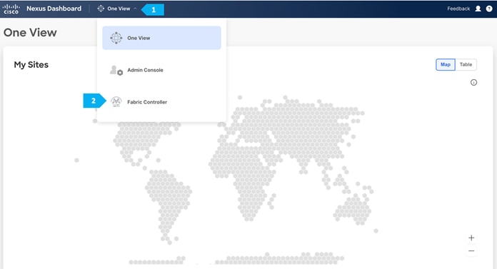
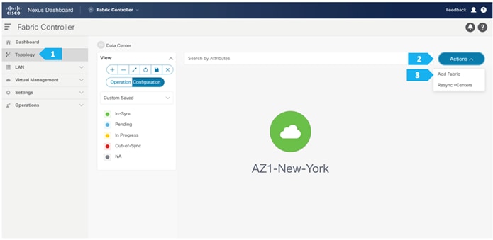
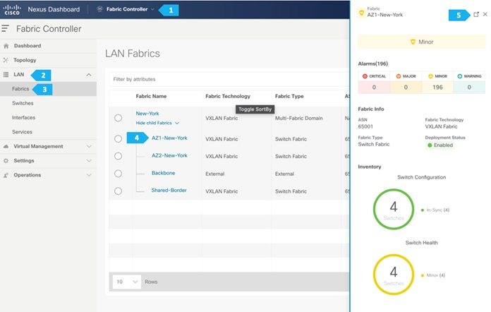
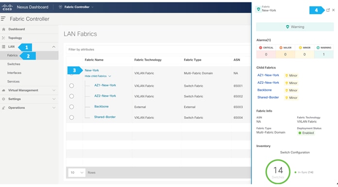
To create all the fabrics above please login to the ND cluster and choose Fabric Controller.
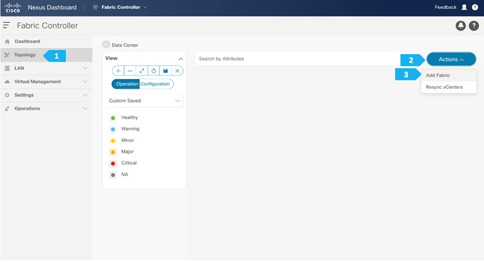
Creating AZ1-New-York Fabric
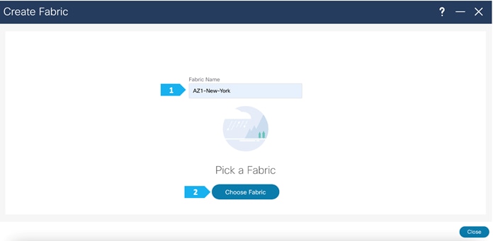
Step 1. Creating the fabric and choosing the template
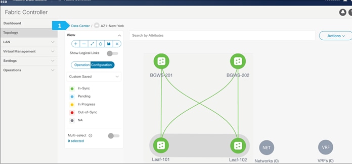
The first fabric that we will be creating is AZ1-New-York, which will be a VXLAN EVPN fabric. It will contain Leaf-101 and Leaf-102 as leaf nodes. For this fabric to be part of VXLAN EVPN Multi-Site, it must have BGWs (Border Gateways) so that it can exchange network and endpoint reachability information using the MP-BGP EVPN overlay control plan with other fabrics. In this fabric, we will show how to use the BGW function using the BGW Spine role by using BGWS-201 and BGWS-202.
AZ1-New-York will use the Data Center VXLAN EVPN fabric template, which is a fabric for a VXLAN EVPN deployment with Nexus 9000 and 3000 switches.
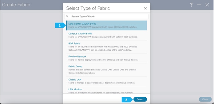
After clicking select we will be presented with a screen with multiple tabs. The overlay and underlay network parameters are included in these tabs.
Please note that the parameters displayed are the minimum to get the fabric up and running and to make it part of a multi-site setup. Please refer to the following link and choose the configuration guide based on the software version being used to understand what each parameter does and to modify the settings based on the specifics of your deployment:
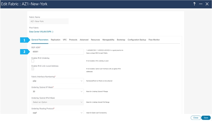
Filling in the parameters in the “General Parameters” tab
In this tab, we will be filling in only the BGP ASN field. Enter the BGP AS number that the fabric is associated with. In this example, will be using 65001 as the BGP ASN.
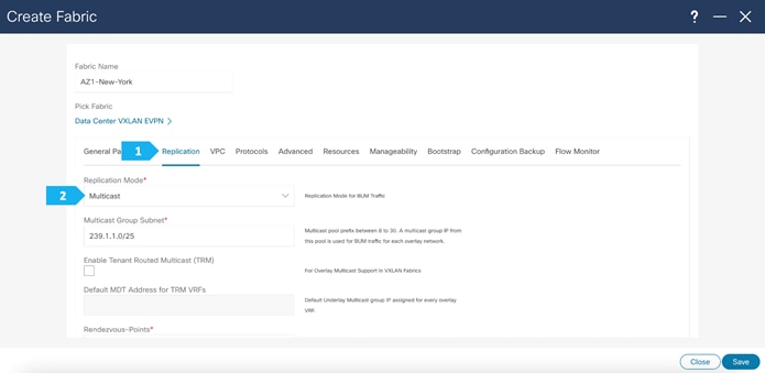
Filling in the parameters in the “Replication” tab
Replication Mode: The mode of replication that is used in the fabric for BUM (Broadcast, Unknown Unicast, Multicast) traffic. The choices are Ingress Replication or Multicast. We will be using the Multicast replication mode.
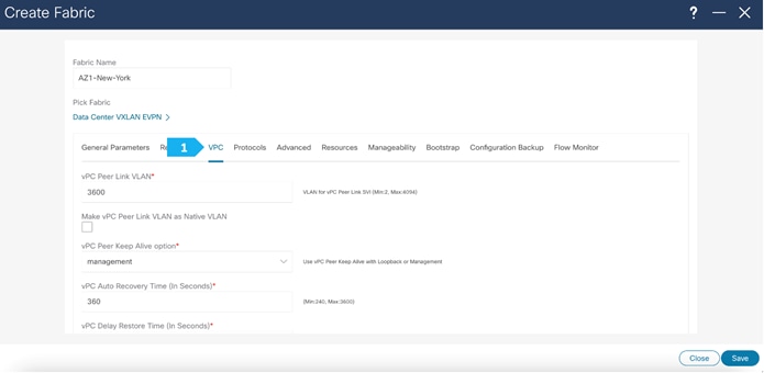
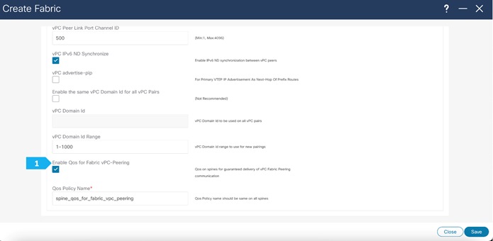
Filling in the parameters in the “vPC” tab
In the AZ1-New-York fabric, we will be using fabric vPC peering which provides an enhanced dual-homing access solution without the overhead of wasting physical ports for vPC Peer Link. This feature preserves all the characteristics of a traditional vPC. We will use all defaults and select only “Enable QoS for Fabric vPC-Peering” to enable QoS on spine switches for guaranteed delivery of fabric vPC peering communication. Please refer to the appropriate configuration guide for guidelines on using QoS for fabric vPC peering.
We can see that all the parameters are automatically populated by NDFC.
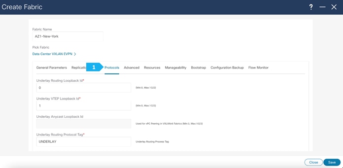
Filling in the parameters in the “Protocols” tab
The Protocol tab is mostly for the parameters used in the underlay. Most of the parameters are automatically generated. For the purpose of this setup, we will leave everything as default.
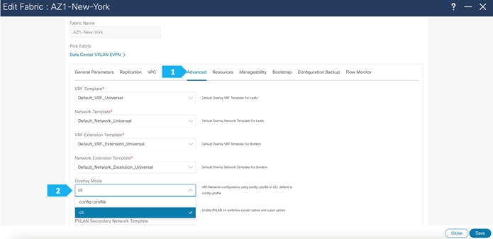
Filling in the parameters in the “Advanced” tab
In the Advanced tab, everything is automatically populated. We will only change the Overlay mode parameters.
Overlay Mode: We can create a VRF or network in CLI or config-profile mode at the fabric level. For the purpose of this setup, we will be using CLI.
Note: Starting with NDFC release 12.1.3b, the default Overlay option for new deployments of the Data Center VXLAN EVPN fabric type is “CLI”.
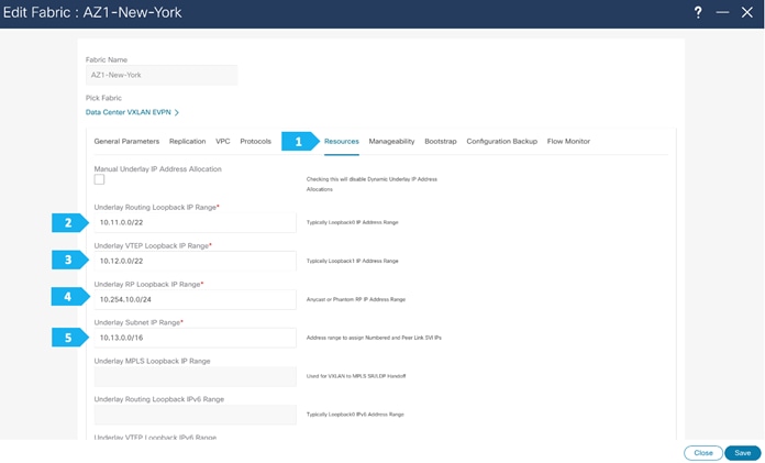
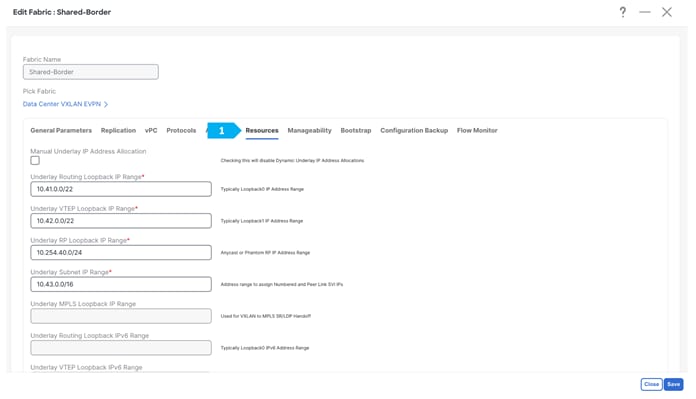
Filling in the parameters in the “Resources” tab
By default, Nexus Dashboard Fabric Controller allocates the underlay IP address resources (for loopbacks, fabric interfaces, and so on) dynamically from the defined pools. It's good practice to enter unique values for the Underlay Routing Loopback IP Range and Overlay VTEP Loopback IP Range fields to proactively avoid duplicate IDs across individual fabrics once we connect them through multi-site.
Filling in the parameters in the “Manageability”, “Bootstrap”, “Configuration Backup” and “Flow Monitor” tabs
We will use the defaults for all these tabs so all what we need to do is to click Save.
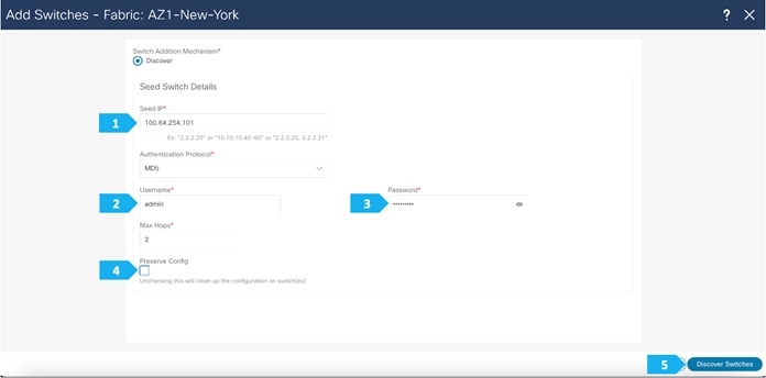
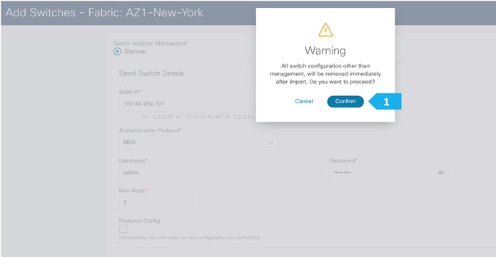
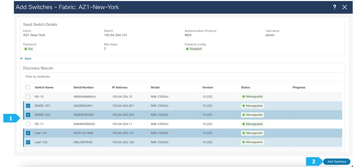
Step 2. Adding switches to the AZ1-New-York Fabric
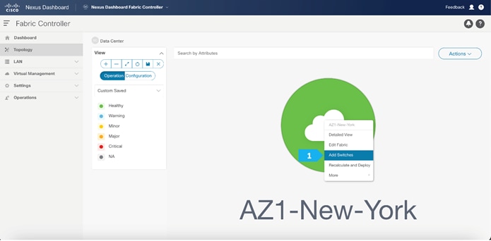
Use seed IP address to discover the switches. We will be using the admin user and password to discover switches. Uncheck preserve config to clear existing switch configurations and reload the devices. Max hop count allows the discovery of connected switches by the number of hops.
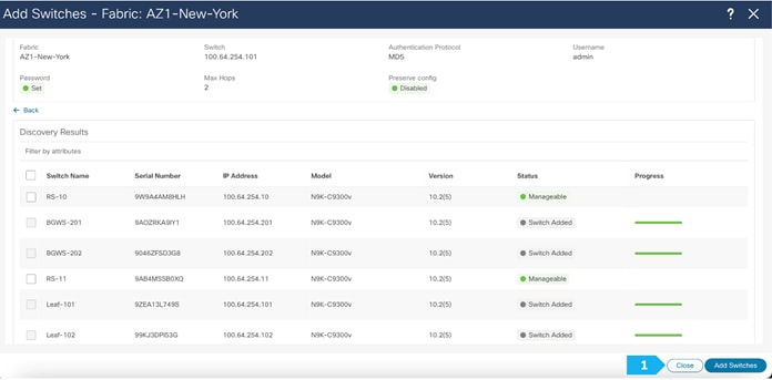
After the switches are discovered, add these switches as part of the AZ1-New-York fabric and click “Add Switches”.
Please wait until the Progress for all switches being added is green, then click Close.
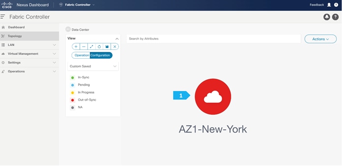
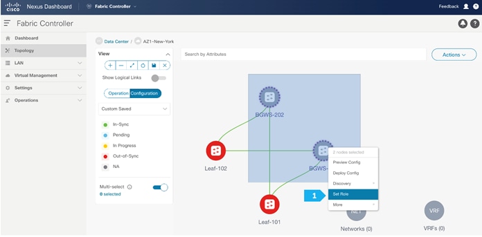
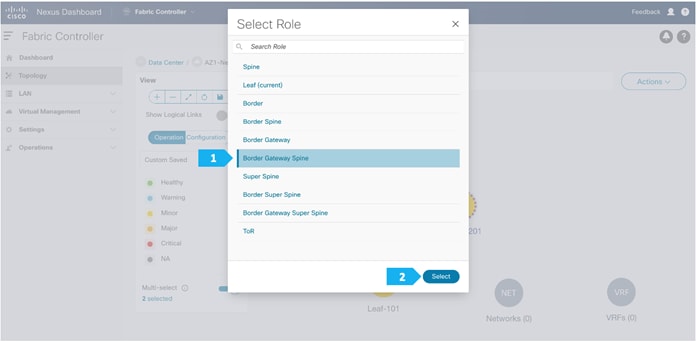
Step 3. Changing the devices’ roles
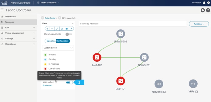
After the devices are added to the AZ1-New-York fabric, they will be assigned a default role depending on the platform. BGWS-210 and BGWS-202 will get the Border Gateway Spine role and Leaf-101 and Leaf-102 will get the Leaf roles, and the relevant configurations will be pushed to the respective devices. We can do these steps after we double-click on the AZ1-New-York fabric as shown in the next screen.
We see the fabric color is red, which means that it is out of sync because the intended configuration that we want is not yet pushed to the switches.
- Toggle the Multi-select option.
- Press Ctrl click and hold anywhere in the whitespace and drag the cursor up, down, left, or right to highlight the BGWS-201 and BGW-202.
- Release the modifier key “ctrl” before releasing the mouse drag to end the switch selection.
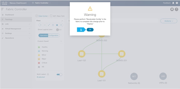
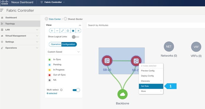
- Right-click and choose Set Role.
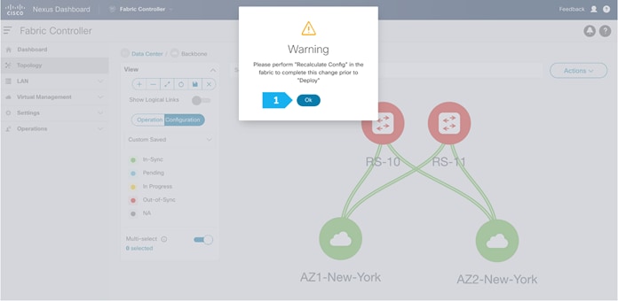
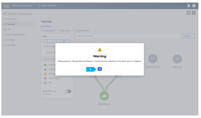
Click Ok in the warning window that appears.
The warning window tells us to perform a Recalculate and Deploy action; however, we will create additional configuration policies described in the next steps before performing the Recalculate and Deploy action.
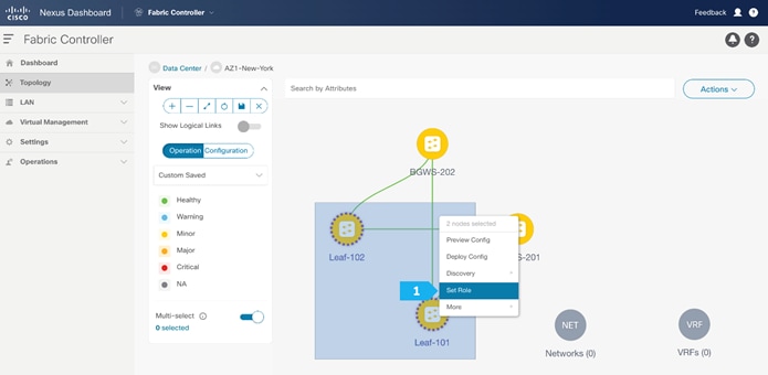
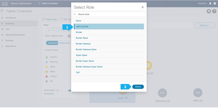
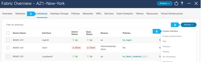
Step 4. Configuring vPC between leaf switches
To configure Leaf-101 and Leaf-102 as vPC Peers, right click on one of the leaf switches and select vPC Pairing.

Select the peer switch to form vPC. In AZ1-New-York we don’t have a direct link between the leaf switches, so fabric peering can be configured by selecting the “Virtual Peerlink”.
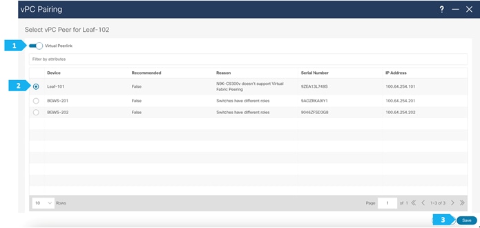
NDFC performs additional checks, such as whether vPC Fabric Peering is supported on the selected device and verifying the minimum NX-OS version and hardware requirement for the feature to be operational. Furthermore, NDFC recommends vPC pairing based on the overall requirement of the feature, thus saving operating time for network admins.
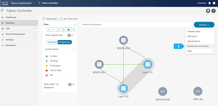
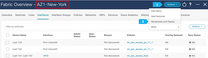
Step 5. Recalculating and deploying to the fabric
At this point, we are ready to push the configuration to the AZ1-New-York fabric. Choose “Recalculate and Deploy” as shown in the next screen.
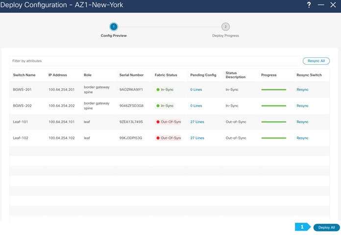
We can click on the “Pending config” for each switch to view the configuration that will be provisioned before clicking “Deploy All”.
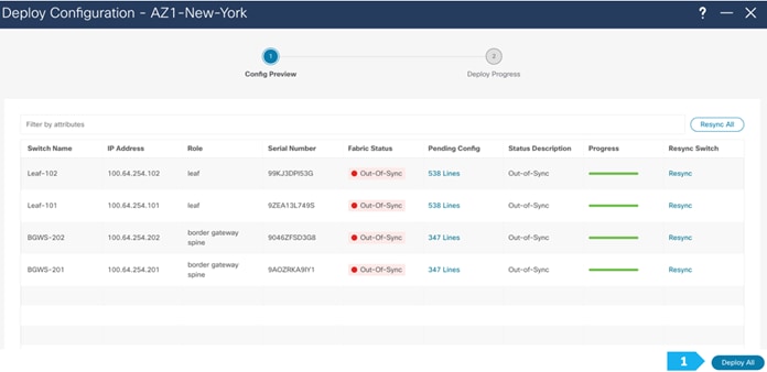
Wait until the “Progress” for all the switches are green before clicking “Close”.

Fabric AZ1-New-York is deployed.
Now all the switches in AZ1-New-York fabric are green, meaning they are “In-Sync”.
Click on Data Center to go to the data center view.
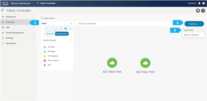
Creating AZ2-New-York Fabric
Creating the fabric and choosing the template
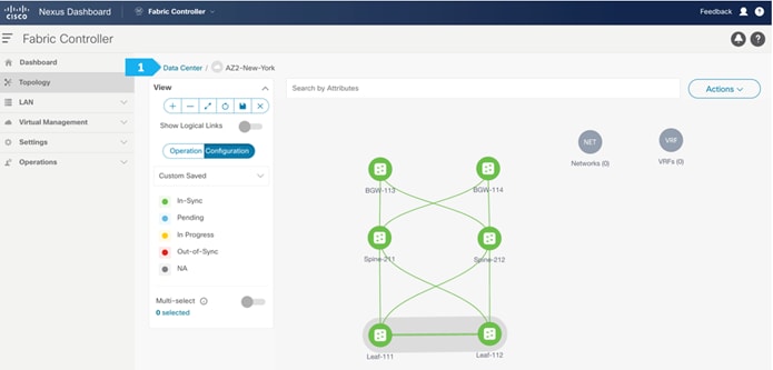
The second fabric that we will be creating is AZ2-New-York, which is a VXLAN EVPN fabri. It will contain Leaf-111 and Leaf-112 as leaf nodes, and Spine-211 and Spine-212 as spine nodes. For this fabric to be part of VXLAN EVPN Multi-Site, it must have BGWs (Border Gateways) so that it can exchange network and endpoint reachability information using the MP-BGP EVPN overlay control plan to other fabrics. In this fabric, we will show how to use the BGW function using dedicated BGW nodes BGW-113 and BGW-114.
AZ2-New-York will also use the Data Center VXLAN EVPN fabric template, which is the option for a VXLAN EVPN deployment with Nexus 9000 and 3000 switches. Repeat all the steps done for AZ1-New-York, where you make sure to choose unique BGP AS number, IP subnet, etc.
Fabric AZ2-New-York is deployed.
After finishing all the steps, the switches in the AZ2-New-York fabric should become green, meaning they are “In-Sync”, and we should have a Topology such as the screen below. Click on “Data Center” to go back to main Topology.
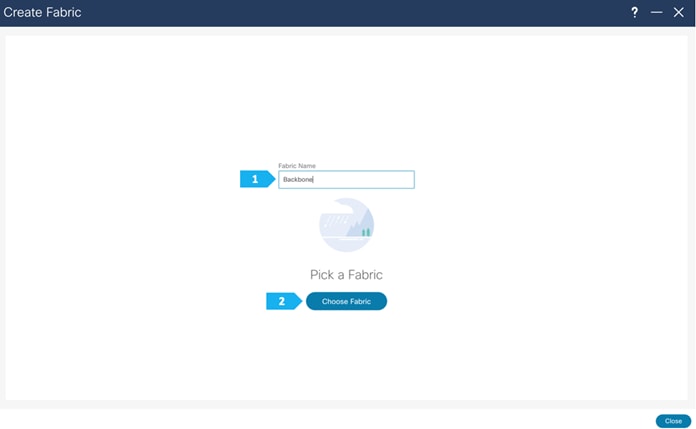
Creating Backbone Fabric
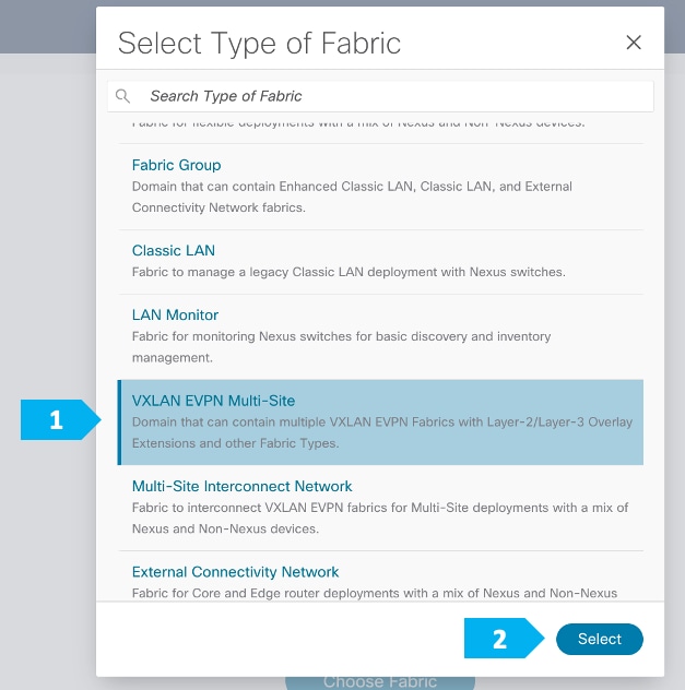
Step 1. Creating the fabric and choosing the template
The third network component that we will be creating is the Backbone. Because this fabric is a Multi-Site Interconnect Network, we will use Route Server (Centralized EVPN peering). With this option, all the BGW nodes deployed in different sites will peer with the same pair of Route Server devices, usually deployed in the Inter-Site Network (ISN).
In the Backbone fabric, we will have RS-10 and RS-11 with the role of “Core Router”. Loopback IP addresses are required on Route Servers to establish BGP EVPN full-mesh peering with the BGW nodes that are associated with different fabrics in the Multi-Site domain.
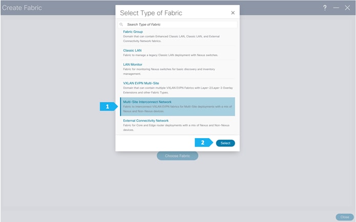
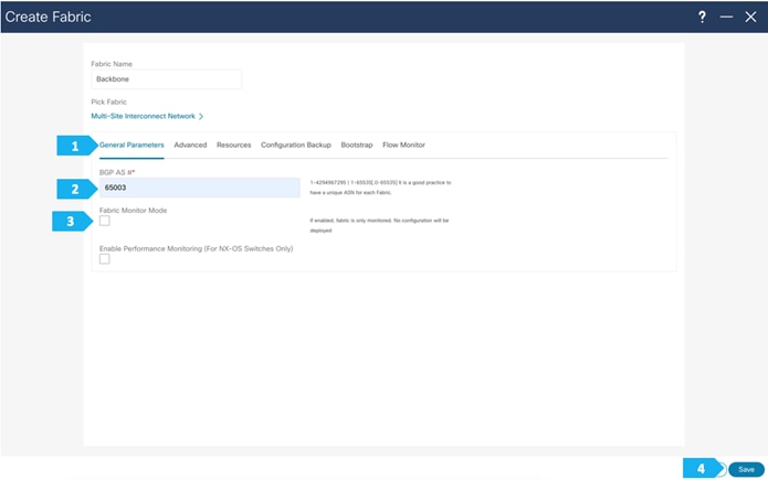
After clicking Select, we will be presented with a screen with multiple tabs. This type of fabric only needs one parameter, which is the BGP AS number; the rest of the parameters in all tabs are automatically populated.
Please note that the parameters displayed are the minimum to get the fabric up and running, and to make it part of a Multi-Site setup. Please refer to the following link and choose the configuration guide based on the software version being used to understand what each parameter does and to modify the settings based on the specifics of your deployment:
Filling in the parameters in the “General Parameters” tab
In this tab, we will be filling in only the BGP ASN. Enter the BGP AS number that is associated with the fabric. In this example, we will be using 65003 as the BGP ASN number.
Note: Please uncheck the “Fabric Monitor Mode” option since NDFC will be managing the devices that belongs to the Multi-Site Interconnect Network.
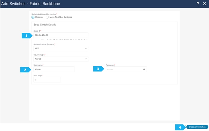
Step 2. Adding switches to the Backbone Fabric
Use a seed IP address to discover the switches. The max hop count allows the discovery of connected switches by the number of hops.
After the switches are discovered, choose the switches to be part of the Backbone fabric and click “Add Switches”.
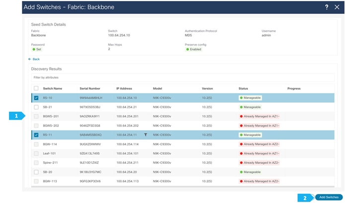
Please wait until the Progress for all of the switches being added is green, then click “Close”.
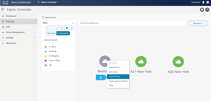
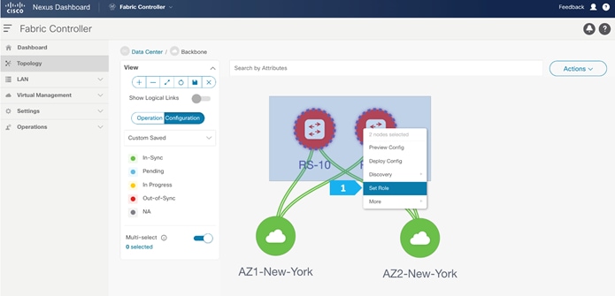
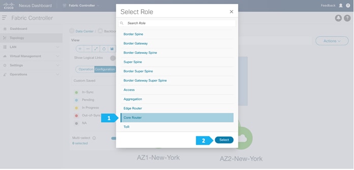
Step 3. Changing the devices’ role
After the devices are added to the Backbone fabric, they will be assigned a default role depending on the platform. In this example configuration, we will assign RS-10 and RS-11 the “Core Router” role. Assigning this role will push the relevant configurations to the respective devices. We can assign this role after we double-click on the Backbone fabric, as shown in the next screen.
We see the fabric color is red, which means that it is out of sync and the intended configuration that we want is not yet pushed to the switches.
Enable the Multi-select option as shown below, then press Ctrl + click and drag your mouse to select RS-10 and RS-11.
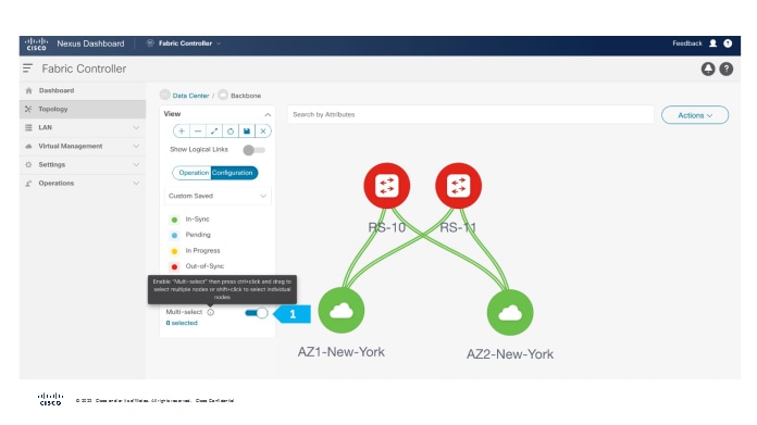
We must release the modifier keys “ctrl” before releasing mouse drag to end the switch selection.
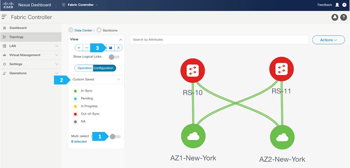
After setting the device role, toggle the Multi-select option to disable the multi-select function.
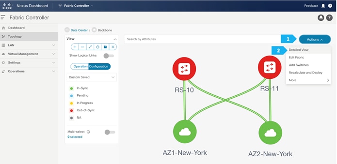
To adjust the topology to look like the screenshot below, choose “Custom Saved” and move the switches around to update the topology like below, then click the save icon as shown.
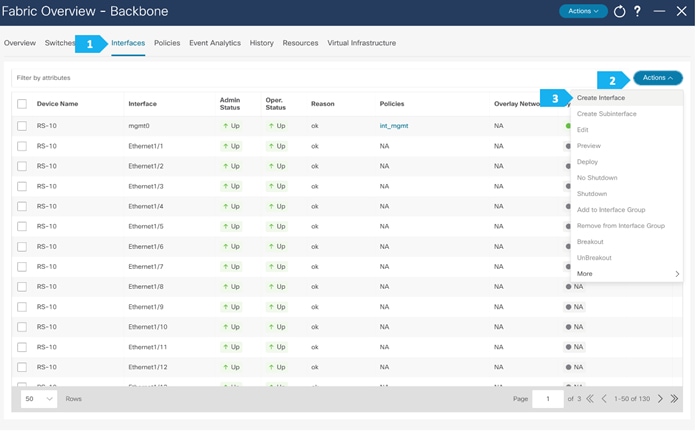
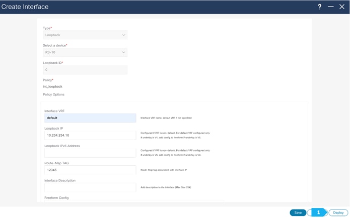
Step 4. Create a loopback interface per each route server
We need to create a loopback on RS-10 and RS-11, following the steps shown in the next screen shots. Loopback IP addresses are required on Route Servers to establish BGP EVPN full-mesh peering with the BGWs that are associated with different fabrics in the Multi-Site domain. Each AZ will deploy dedicated BGWs that will peer with the Route Servers.
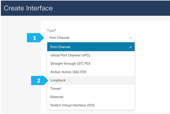
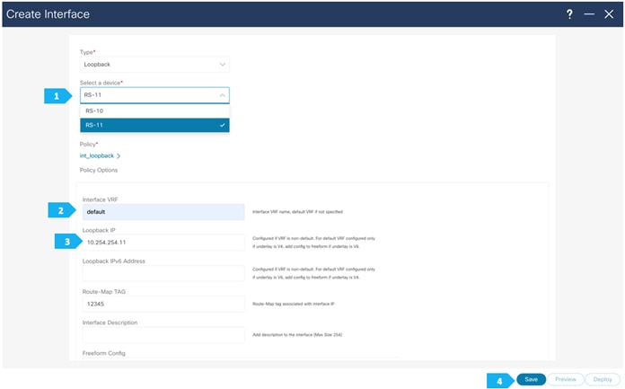
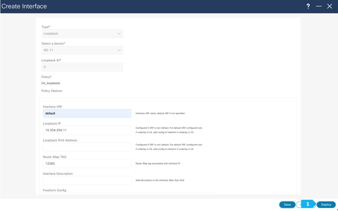
We need to choose one of the Route Server nodes from the drop down menu as show. The loopback must be provisioned in the “default” VRF. Repeat for both RS-10 and RS-11.
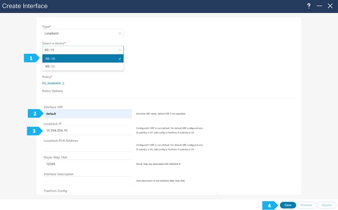
Please repeat the the same steps for RS-11.
Step 5. Recalculate and Deploy to the fabric
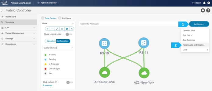
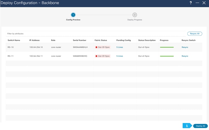
We can click on the “Pending config” for each switch to view the configuration before clicking “Deploy All”.
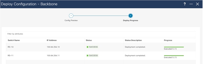
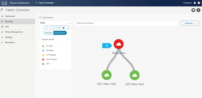
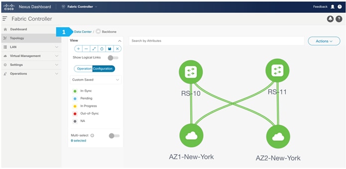
Backbone Fabric is deployed.
Now all of the switches in the “Backbone” fabric are green, meaning they are “In-Sync” with the intended configuration on NDFC. Click on “Data Center” to go back to main Topology.
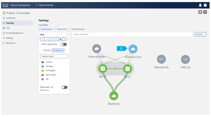
Creating Shared-Border Fabric
Step 1. Creating the fabric and choosing the template
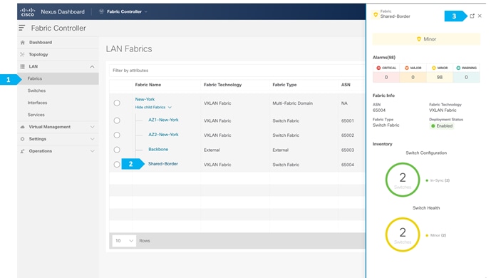
The fourth fabric that we will be creating is Shared-Border, which is a VXLAN EVPN fabric containing SB-20 and SB-21 with the role of “Border”.
The shared border acts as a common external connectivity point for multiple VXLAN BGP EVPN fabrics that are part of the same EVPN Multi-Site architecture. Unlike the BGW, the shared border is completely independent of any VXLAN EVPN Multi-Site software or hardware requirements. It is solely a border node topologically residing outside of a VXLAN EVPN fabric. The shared border operates like a traditional VTEP, but unlike the site-internal VTEPs discussed previously, the shared border is a site-external VTEP.
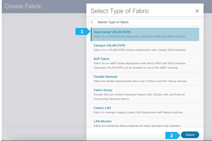
After clicking Select, we will be presented with a screen with multiple tabs. The overlay and underlay network parameters are included in these tabs.
Please note that the parameters displayed are the minimum to get the fabric up and running and to make it part of a multi-site setup. Please refer to the following link and choose the configuration guide based on the version that you will be using to understand what each parameter does and to make changes based on our design:
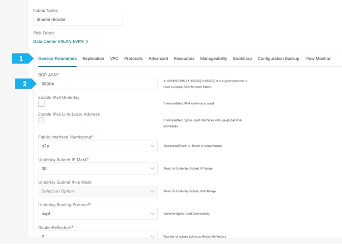
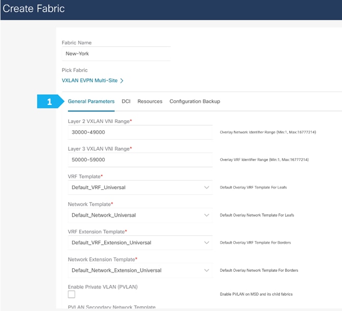
Filling in the parameters in the “General Parameters” tab
In this tab, we will be entering information only in the BGP ASN field. Enter the BGP AS number that the fabric is associated with. In this example, will be using 65004 as the BGP ASN.
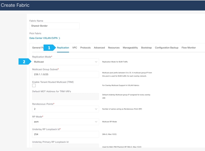
Filling in the parameters in the “Replication” tab
Replication Mode: This is the mode of replication that is used in the fabric for BUM (Broadcast, Unknown Unicast, Multicast) traffic. The choices are Ingress Replication or Multicast. We will be using the Multicast replication mode.
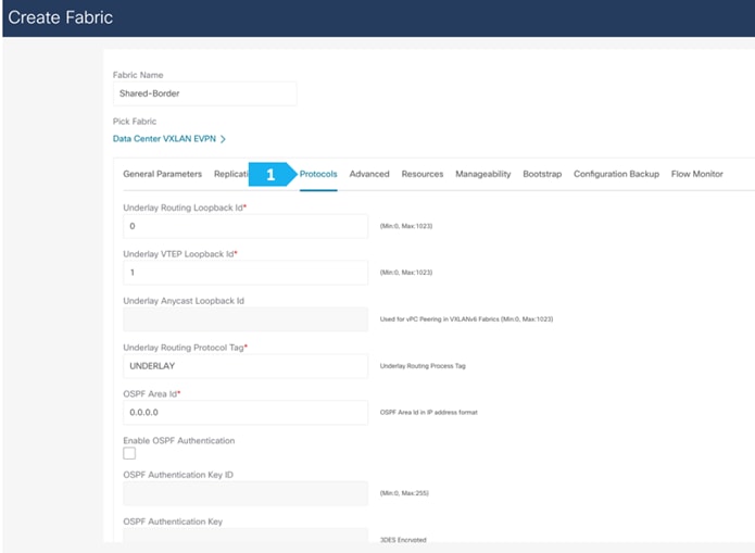
Filling in the parameters in the “Protocols” tab
The Protocol tab is mostly for the parameters used in the underlay. Most of the parameters are automatically generated. For the purpose of this setup, we will leave everything with the default settings.
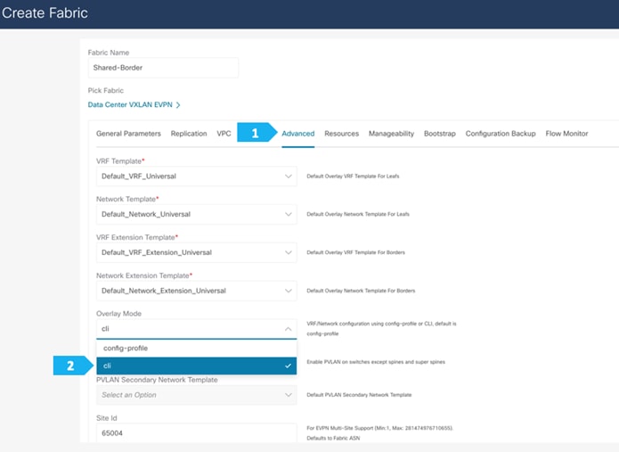
Filling in the parameters in the “Advanced” tab
In the Advanced tab, everything is automatically populated. We will only change the setting in the Overlay mode field.
Overlay Mode: We can create a VRF or network in CLI or config-profile mode at the fabric level. We will be using CLI for this example configuration.
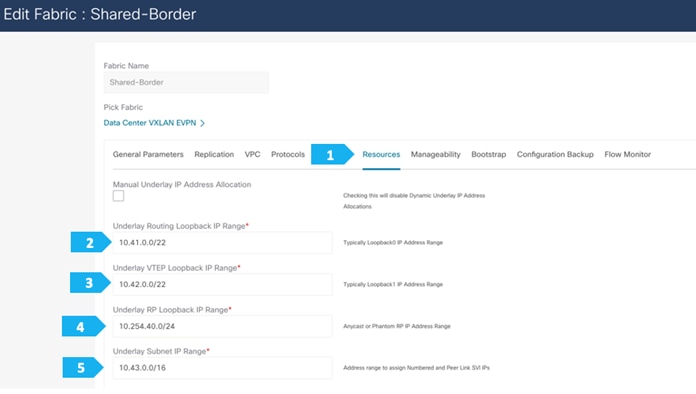
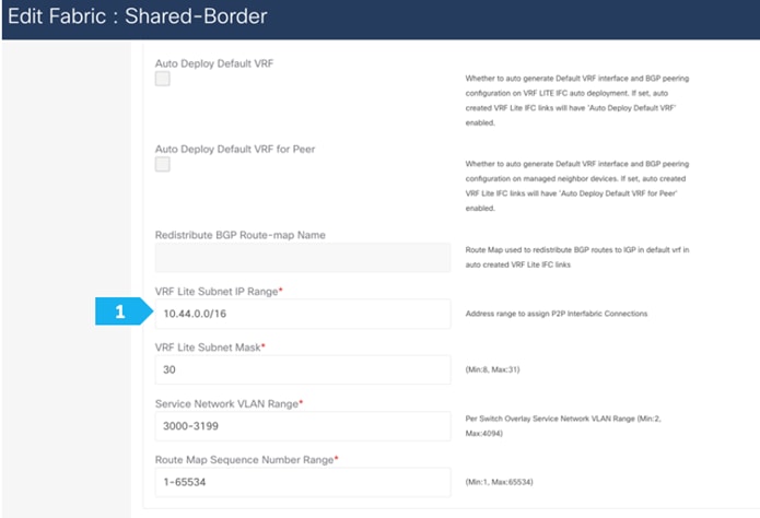
Filling in the parameters in the “Resources” tab
By default, Nexus Dashboard Fabric Controller dynamically allocates the underlay IP address resources (for loopbacks, fabric interfaces, and so on) from the defined pools. Please make sure to choose a unique pool per fabric.
Filling in the parameters in the “Manageability”, “Bootstrap”, “Configuration Backup” and “Flow Monitor” tabs
We will use the defaults for all these tabs, so all what we need to do is to click Save in each window.
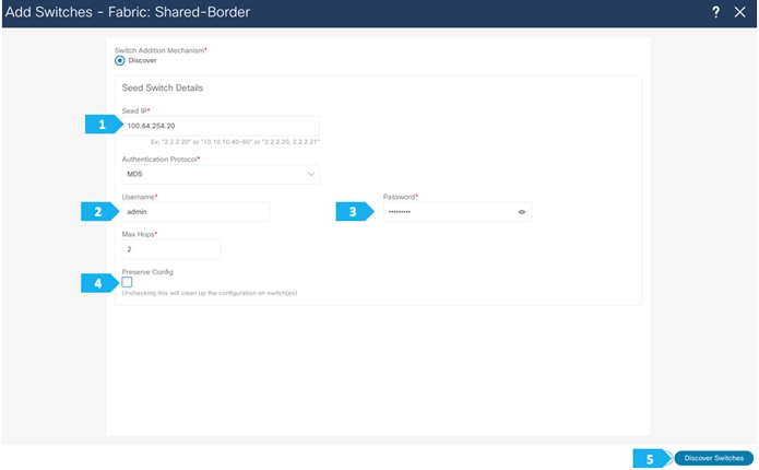
Step 2. Adding switches to the Shared-Border Fabric
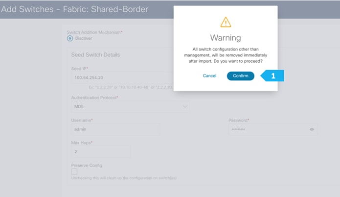
Use seed IP address to discover the switches. We will use the admin username and password to discover the switches. Uncheck the “Preserve Config” option to clear the switch configuration and to reload the devices. Max hop count allows for the discovery of connected switches by the number of hops.
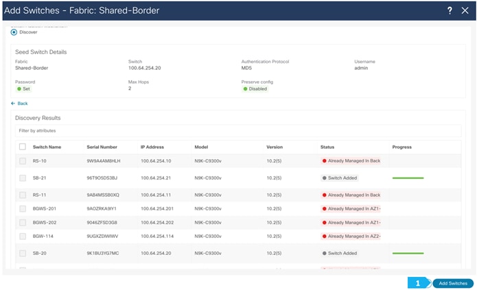
After the switches are discovered, add these switches to be part of the Shared-Border fabric, then click “Add Switches”.
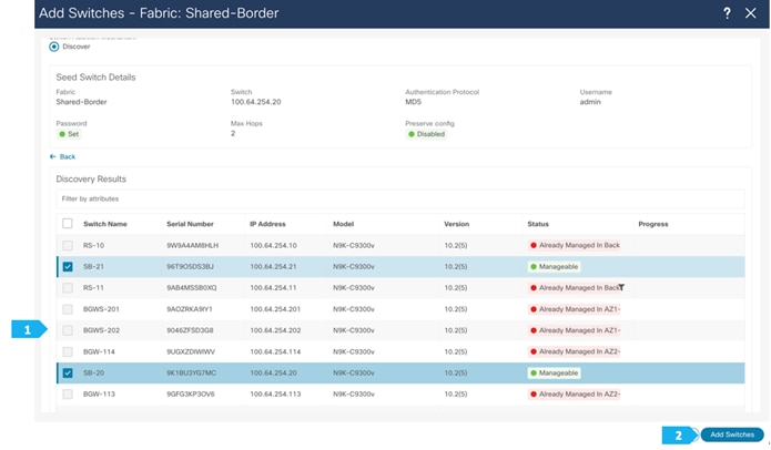
Please wait until the Progress for all switches being added is green, then click Close.
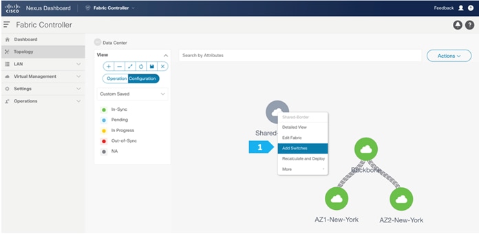
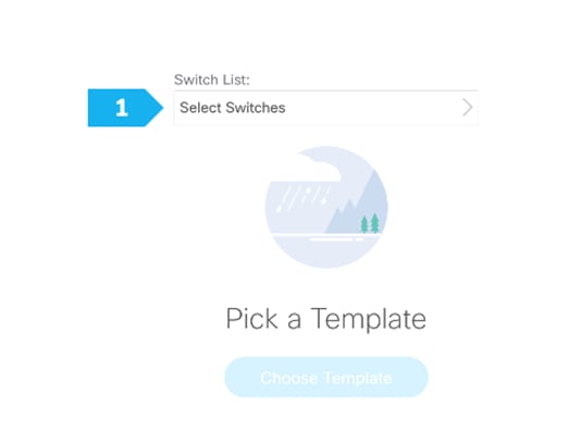
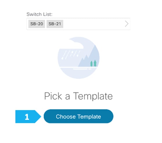
Step 3. Changing the devices’ role
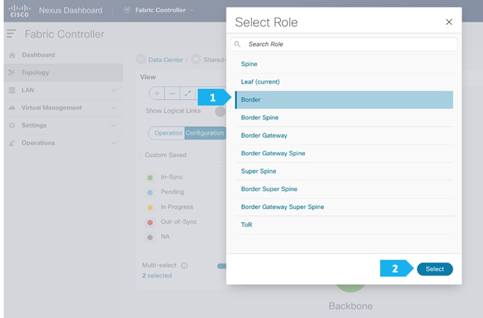
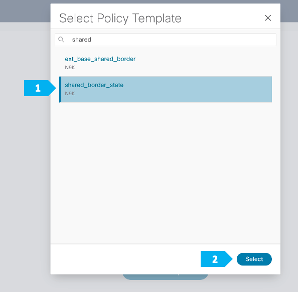
After the devices are added to the Shared-Border fabric, they will be assigned a default role depending on the platform. SB-20 and SB-21 will get the “Border” role, which will push the relevant configuration to the respective devices. We can assign this role after we double-click on the Shared-Border fabric as shown in the next screen.
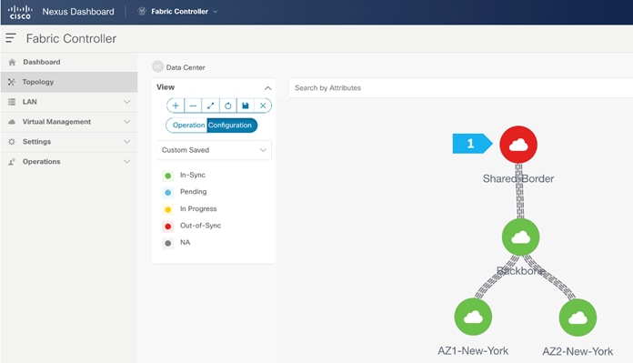
We see the fabric color is red, which means that it is out of sync and the intended configuration that we want is not yet pushed to the switches.
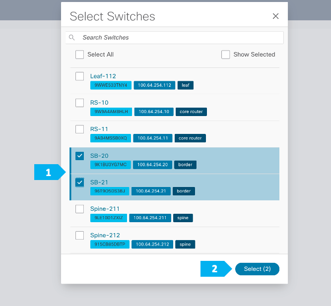
Enable Multi-Select as shown and press Ctrl + click, then drag the mouse to select SB-20 and SB-21. You must release the modifier key “ctrl” before releasing the mouse drag to end the switch selection.
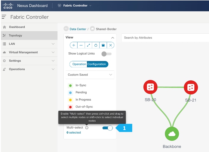
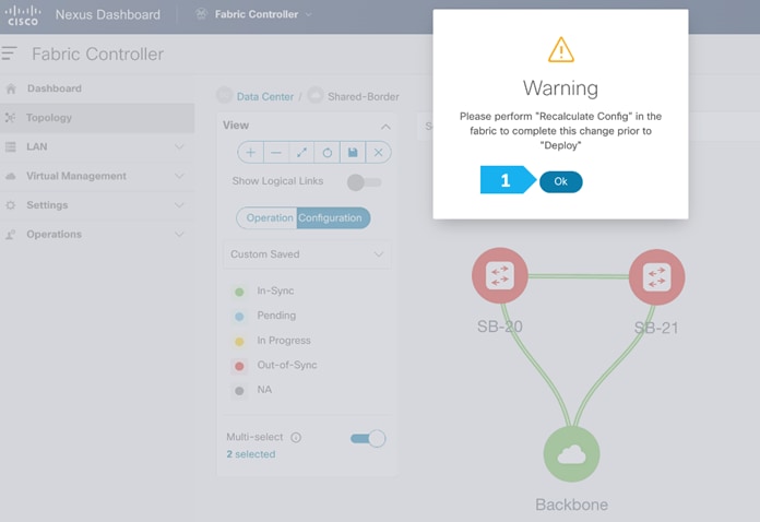
After setting the role, toggle the Multi-select option to disable the multi-select function.
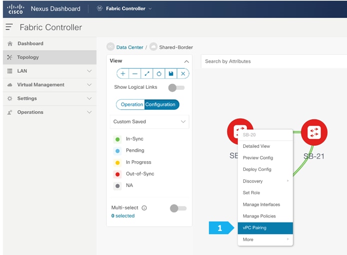
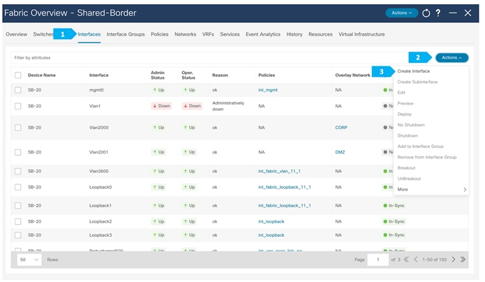
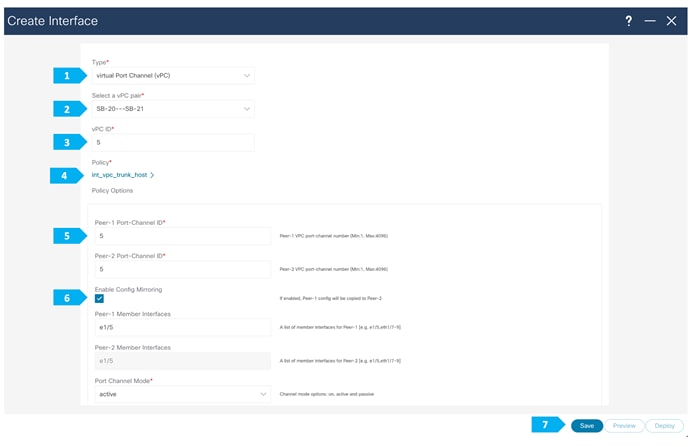
Step 4. Configure vPC between borders
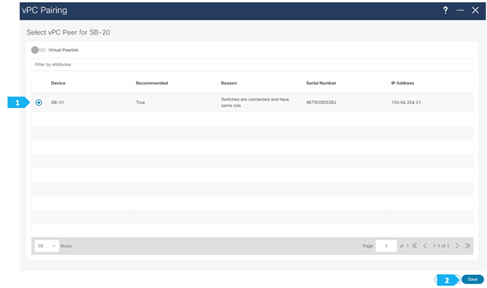
To configure SB-20 and SB-21 as vPC Peers, click on one of the leaf switches and select vPC Pairing.
Note: The Shared-Borders are independent Layer 3 VTEPs. The vPC pairing is optional and only required for connecting Site-External service nodes, such as firewall, load balancer, TCP Optimizers, and so on.
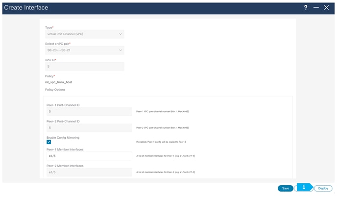
Select the peer switch and click Save.
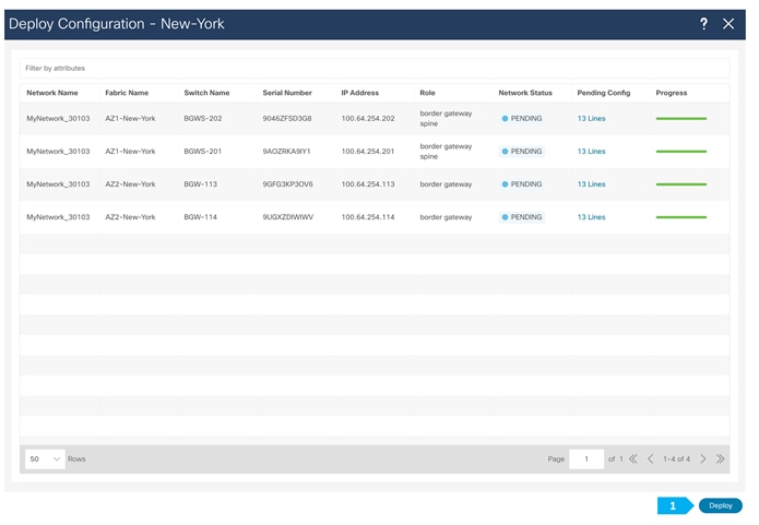
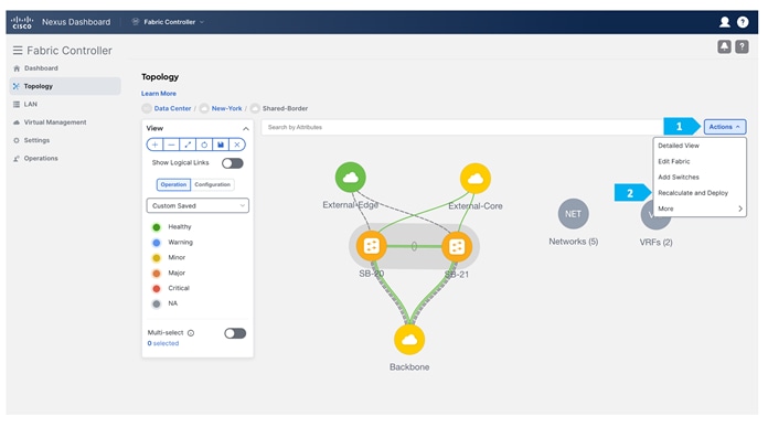
Step 5. Recalculate and Deploy to the fabric
At this point, we are ready to push the configuration to the Shared-Border fabric. Choose “Recalculate and Deploy” as shown in the next screen.
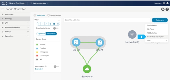
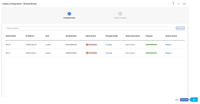
We can click on the “Pending config” for each switch to view the configuration before clicking “Deploy All”.
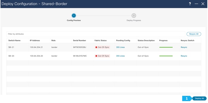
Wait until the “Progress” for each of the switches shows green before clicking “Close”.
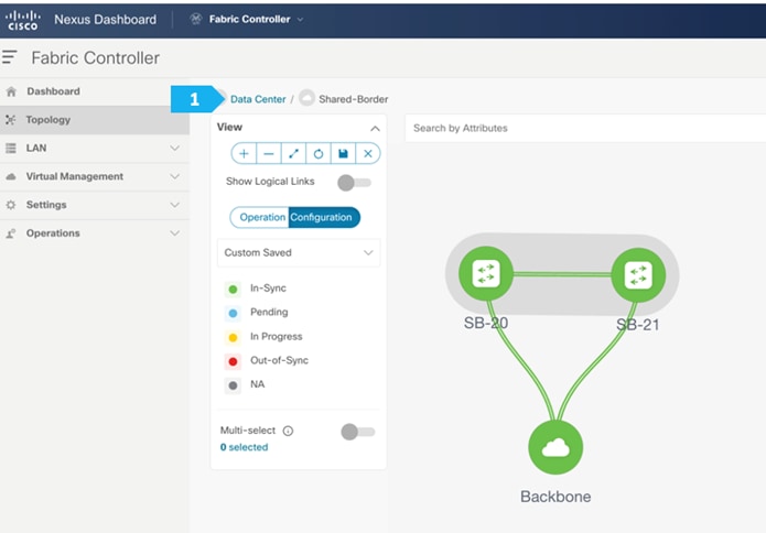
Shared-Border Fabric is deployed.
Now all of the switches in the Shared-Border fabric are green, meaning they are “In-Sync”.
Click on “Data Center” to go back to the main topology view.
Creating New-York MSD Fabric
Step 1. Creating the fabric and choosing the template
The third fabric that we will be creating is the New-York Multi-Site Domain (MSD) fabric. A Multi-Site Domain is a multi fabric container that is created to manage multiple member fabrics.
An MSD is a single point of control for the definition of overlay networks and VRFs that are shared across member fabrics. When we move fabrics that are designated to be part of the Multi-Site overlay network domain under the MSD as member fabrics, these member fabrics share the networks and VRFs created at the MSD level. This way, we can consistently provision network and VRFs for different fabrics at one go. It significantly reduces the time and complexity involving multiple fabric provisioning.
As server networks and VRFs are shared across the member fabrics as one stretched network, the provisioning function for the new networks and VRFs is provided at the MSD fabric level. The creation of any new network or VRF is only allowed in the MSD. All member fabrics inherit any new network and VRF created for the MSD.
The topology view for the MSD fabric displays all member fabrics and how they are connected to each other in one view. We can deploy overlay networks and VRFs on member fabrics from a single topology deployment screen instead of visiting and deploying from each member fabric deployment screen separately.
Filling in the parameters in the “General Parameters” tab
All the parameters in the General Parameters tab will be automatically populated.
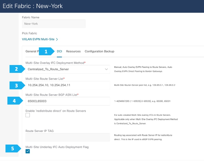
Filling in the parameters in the “DCI” tab
Since we will be employing the Route Server design using RS-10 and RS-11, we need to the change the “Multi-Site Overlay IFC Deployment Method” to the “Centralized_To_Route_Server” option. We need to supply the Loopback IP addresses as well as the BGP AS number for RS-10 and RS-11 that we created in the Backbone fabric as shown in the next screen shot.
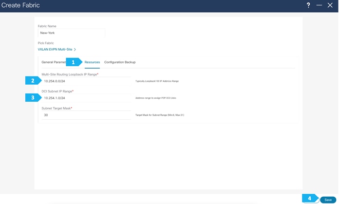
Filling in the parameters in the “Resources” tab
In the Resources tab, we need to supply the Multi-Site routing loopback IP range and the DCI subnet IP range.
Step 2. Moving Fabrics Under the MSD Fabric as a Member
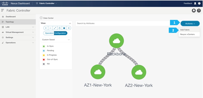
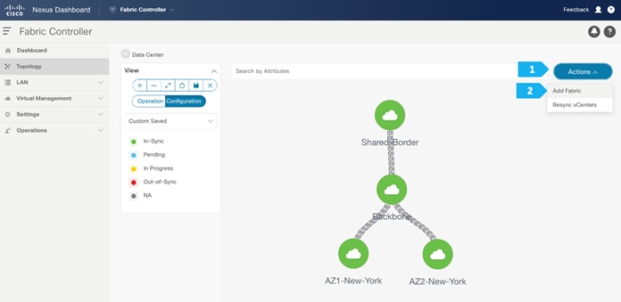
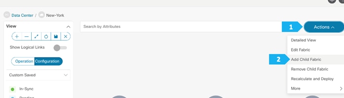
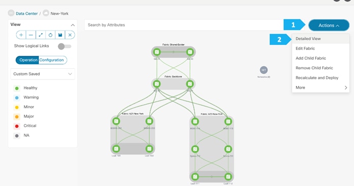
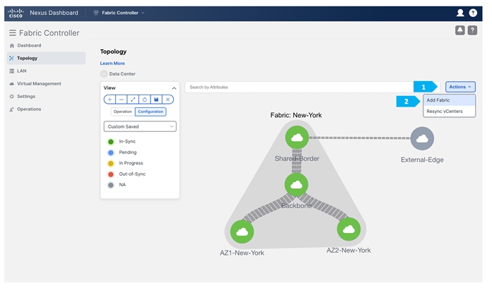
Double-click on the New-York MSD fabric, then click Actions > Add Child Fabric and start adding all the fabrics as member fabrics.
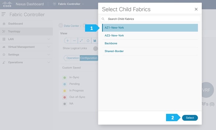
We can also click Detailed View > Actions > Add Child Fabrics to add member fabrics to the MSD. A list of child fabrics that are not part of any MSD appears. Member fabrics of other MSD container fabrics are not displayed here.
As AZ1-New-York fabric is to be associated with the New-York MSD fabric, select the AZ1-New-York fabric, and click Select.
We can see that AZ1-New-York is now added to the MSD fabric and is displayed in the Child Fabrics in the Fabrics list table.
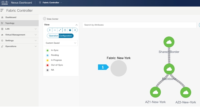
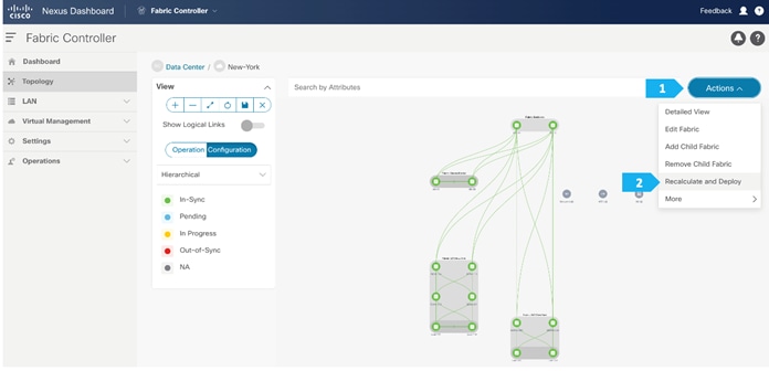
Repeat these steps for all the fabrics until all the fabrics are part of the New-York MSD fabric. Click on Hierarchical view and click Save. We can also drag and move the fabrics around with the mouse cursor to achieve the view that we want.
Step 3. Recalculate and Deploy to the fabric
In the next few screens, we will go through a sample CLI on RS-10 and BGW-114.
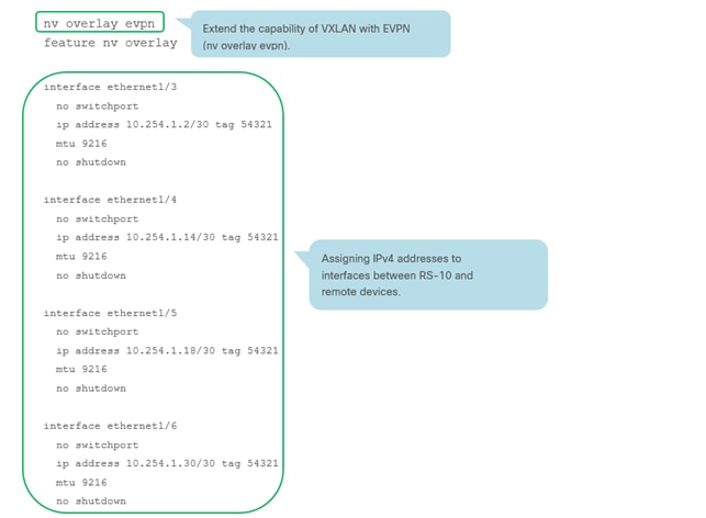
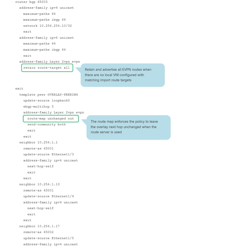
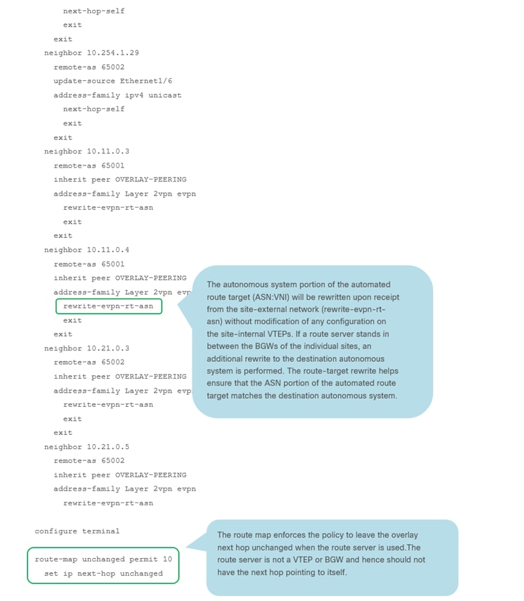
RS-10 Sample CLI (Route Server)
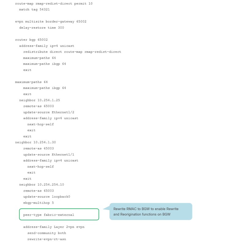
BGW-114 Sample CLI (Border Gateway)
Note: For more information on Multi-Site designs and configurations, please see the following link: https://www.cisco.com/c/en/us/products/collateral/switches/nexus-9000-series-switches/white-paper-c11-739942.html
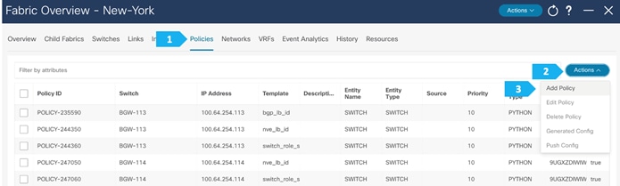
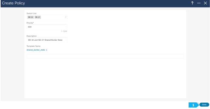
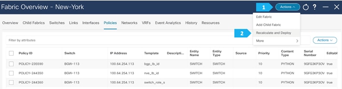
Step 4. Add the necessary policy to allow NDFC to deploy the VXLAN EVPN Multi-Site configuration on the shared border switches
By default, NDFC deploys the VXLAN EVPN Multi-Site configuration on switches with the role of border gateway or core router. NDFC does not deploy the configuration on any switch that does not have a role of border gateway or core router, even if those devices are part of the Multi-Site domain.
In this Shared-Border use case, we want to make sure that NDFC automates the VXLAN EVPN Multi-Site underlay and overlay configuration along with the rest of the devices. This step adds the necessary policy so that NDFC deploys the VXLAN EVPN Multi-Site configuration on the Shared Border switches.
Note: The Shared-Border is a normal “Border” VTEP and is independent of the VXLAN Multi-Site capabilities of BGW (Border Gateway). The configurations shown in the subsequent steps are necessary to enable EVPN Control Plane peering to receive the Type-2 and Type-5 routes from the respective BGWs.
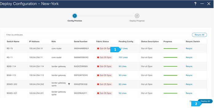
We can click on “Pending Config” to see the cli that will get pushed out. However, what is going to happen is:
- The RS-10 and RS-11 interfaces facing SB-201 and SB-21 will get an IP address and vice versa.
- The eBGP between RS-10 and RS-11, and between SB-20 and SB-21, will also be added.
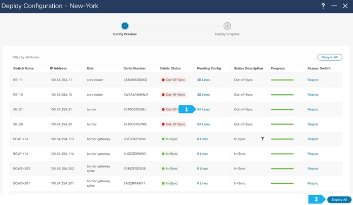
We can click on “Pending Config” to see the cli that will get pushed out, as shown in the next few screen shots.
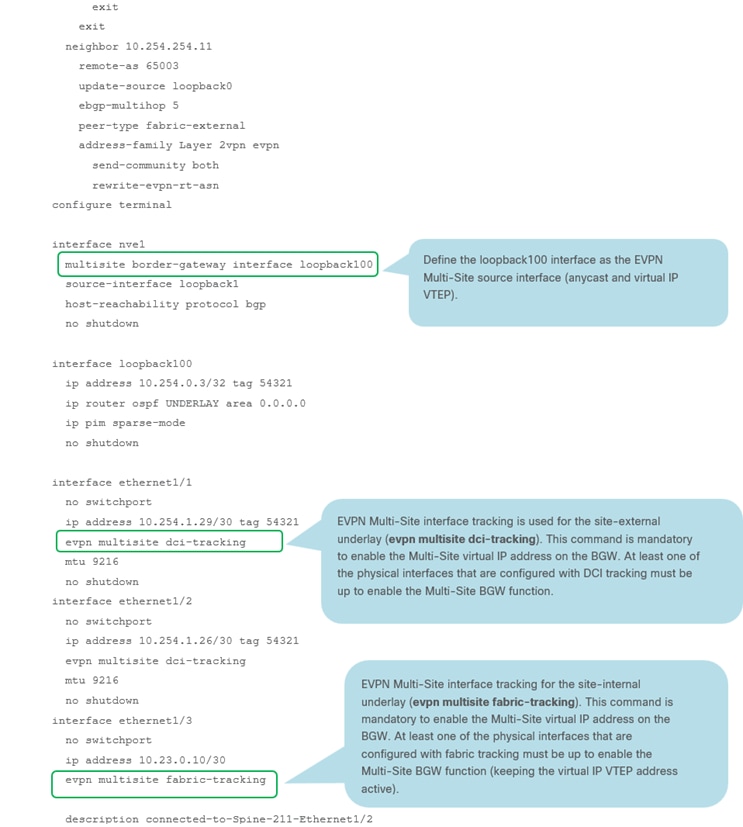
SB-21 Sample CLI (Shared-Border)
route-map rmap-redist-direct permit 10
match tag 54321
router bgp 65004
address-family ipv4 unicast
redistribute direct route-map rmap-redist-direct
maximum-paths 64
maximum-paths ibgp 64
exit
address-family ipv6 unicast
maximum-paths 64
maximum-paths ibgp 64
exit
neighbor 10.254.1.42
remote-as 65003
update-source Ethernet1/2
address-family ipv4 unicast
next-hop-self
exit
exit
neighbor 10.254.1.46
remote-as 65003
update-source Ethernet1/1
address-family ipv4 unicast
next-hop-self
exit
exit
neighbor 10.254.254.10
remote-as 65003
update-source loopback0
ebgp-multihop 5
address-family Layer 2vpn evpn
send-community both
rewrite-evpn-rt-asn
exit
exit
neighbor 10.254.254.11
remote-as 65003
update-source loopback0
ebgp-multihop 5
address-family Layer 2vpn evpn
send-community both
rewrite-evpn-rt-asn
configure terminal
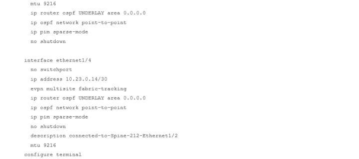
interface ethernet1/1
no switchport
ip address 10.254.1.45/30 tag 54321
mtu 9216
no shutdown
interface ethernet1/2
no switchport
ip address 10.254.1.41/30 tag 54321
mtu 9216
no shutdown
configure terminal
RS-10 Sample CLI (Route Server)
interface ethernet1/1
no switchport
ip address 10.254.1.37/30 tag 54321
mtu 9216
no shutdown
interface ethernet1/2
no switchport
ip address 10.254.1.42/30 tag 54321
mtu 9216
no shutdown
router bgp 65003
neighbor 10.254.1.38
remote-as 65004
update-source Ethernet1/1
address-family ipv4 unicast
next-hop-self
exit
exit
neighbor 10.254.1.41
remote-as 65004
update-source Ethernet1/2
address-family ipv4 unicast
next-hop-self
exit
exit
neighbor 10.41.0.1
remote-as 65004
inherit peer OVERLAY-PEERING
address-family Layer 2vpn evpn
rewrite-evpn-rt-asn
exit
exit
neighbor 10.41.0.2
remote-as 65004
inherit peer OVERLAY-PEERING
address-family Layer 2vpn evpn
rewrite-evpn-rt-asn
configure terminal
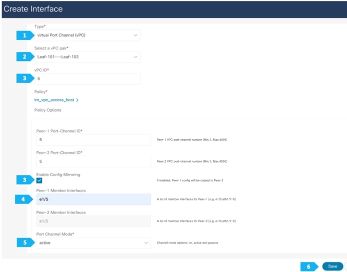
Creating vPCs, VRFs, and Networks
We will be attaching four hosts to the leaf switches as follows:
- Host-1011 and Host-1031 will be connected using a vPC in the fabric AZ1-New-York to Leaf-101 and Leaf-102
- Host-1021 and Host-1032 will be connected using a vPC in the fabric AZ2-New-York to Leaf-111 and Leaf-112
We will show how to create one vPC in the following steps. Please create the remaining vPCs based on the same procedures.
After you have created the required vPC, perform a “Recalculate and Deploy” in each fabric. We will show how to do this for the fabric AZ1-New-York; repeat the same steps for the fabric AZ2-New-York.
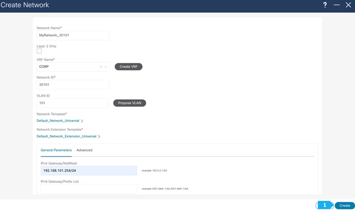
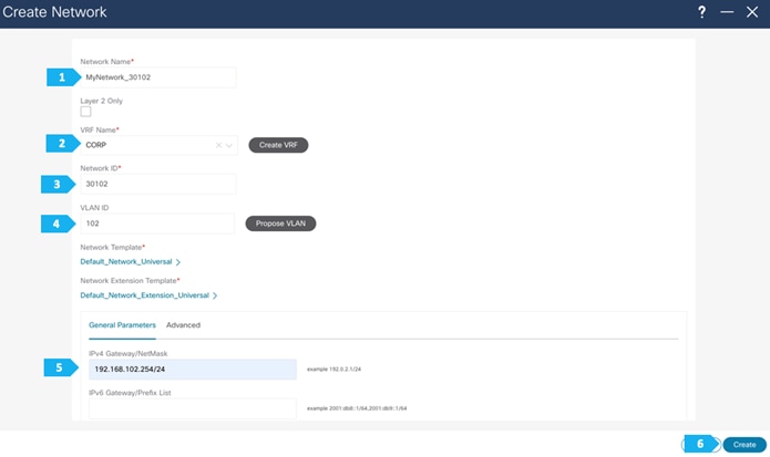
In this section, we will create vPCs, VRFs and networks. The following procedures are just an example to demonstrate the concept. Feel free to choose the VRF names and IP addresses based on our setup.
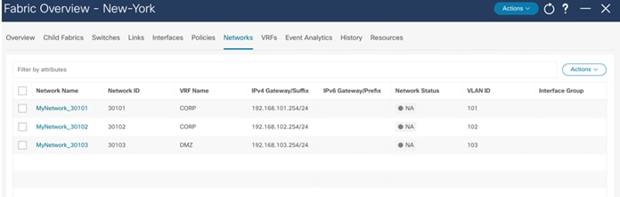
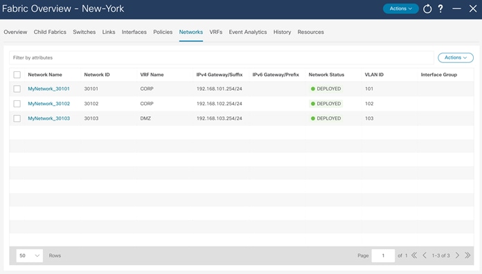
VRF CORP (Internal private networks):
- Network 192.168.101.0/24 will contain Host-1011
- Network 192.168.102.0/24 will contain Host-1021
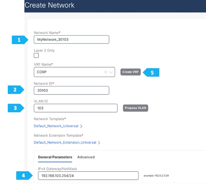
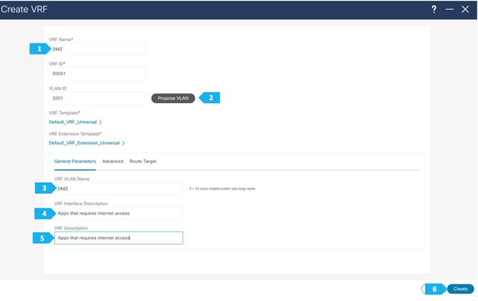
VRF DMZ (App that requires internet or SaaS apps):
- Network 192.168.103.0/24 will contain Host-1031, Host-1032
Note: We can also double-click on the “New-York” MSD fabric to go directly to the next page.
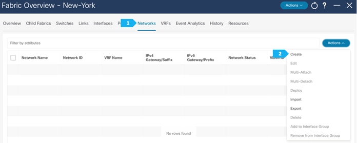
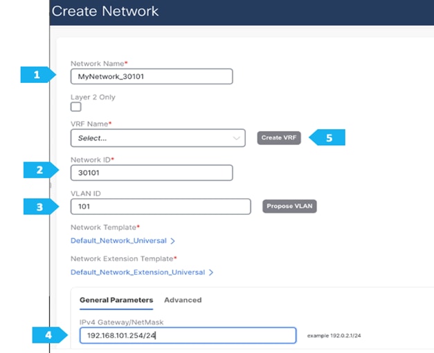
Note: We will be showing how to create VRFs from the Create Network tab. If you prefer to create VRFs first, then create VRFs from the VRF tab; the VRF will then be available to select when we create the network in this case.

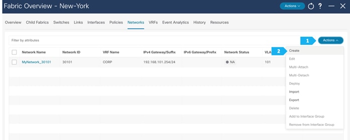
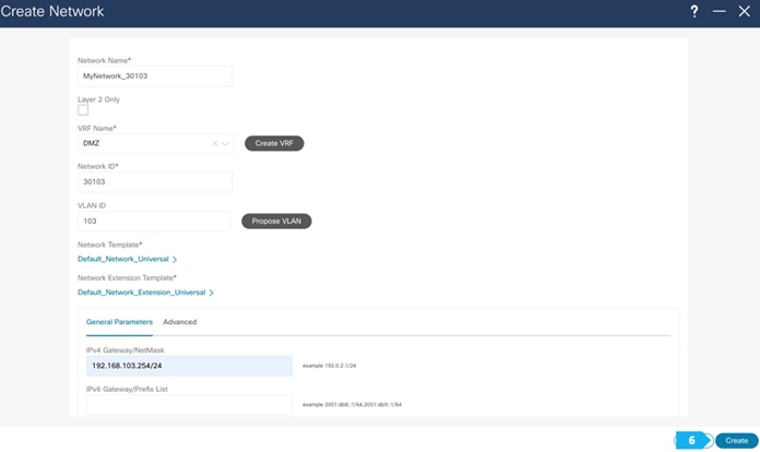
Now we will start attaching networks to interfaces as per the lab setup.
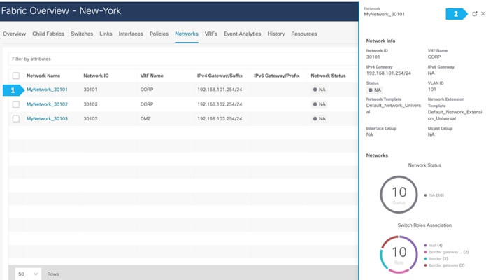
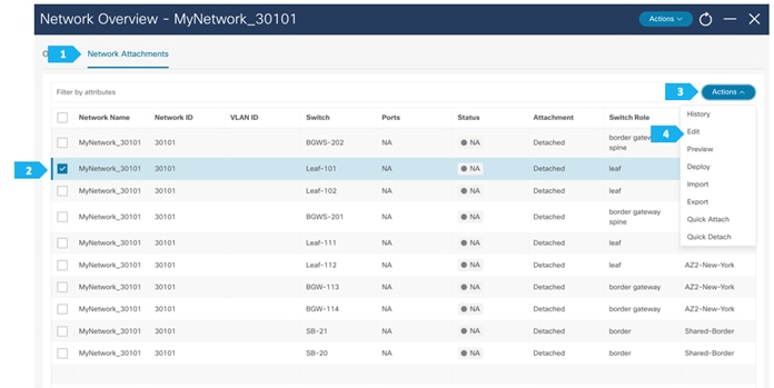
Note: We can also double-click on “MyNetwork_30101” to go directly to the next page.
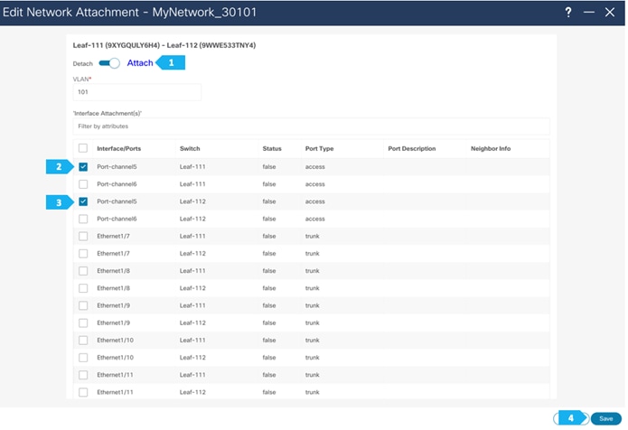
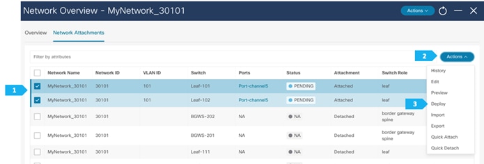
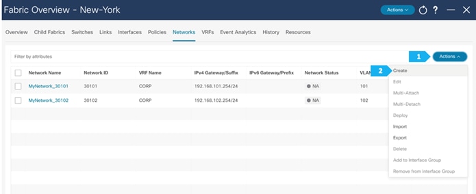
Repeat the previous steps to attach networks for the remaining hosts.
In order to extend Layer 2/Layer 3 between fabrics, we need to push the VRFs CORP and DMZ to the BGWs for type-5 routes to get extended between the fabrics. To extend type-2 routes as well, we need to attach the networks to the BGWs.
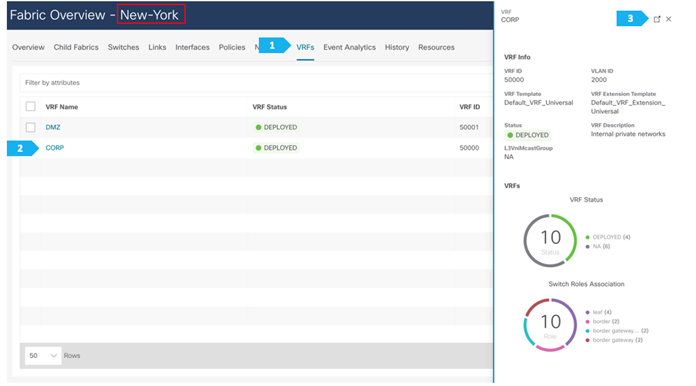
Note: We can double-click on the VRF CORP to go to the next page.
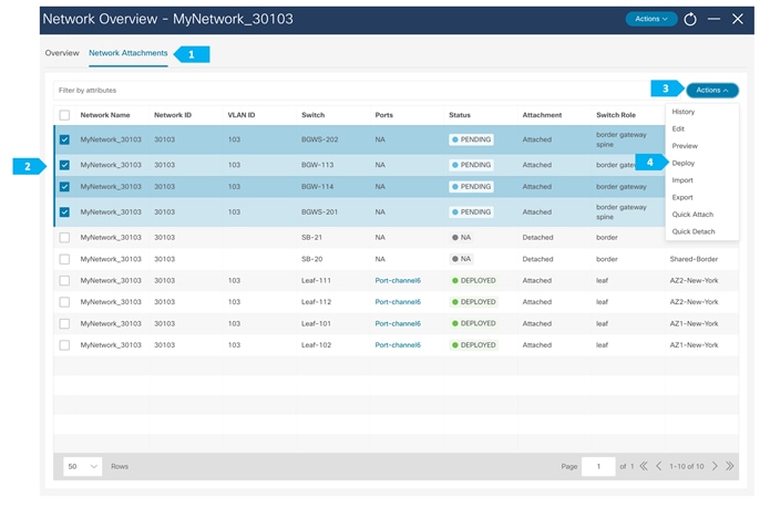
For the VRF DMZ, Host-1031 and Host-1032 are in same VLAN, so to be able to extend Layer 2 and send/receive TYPE-2 routes, we need to attach the network 192.168.103/24 to the BGWs in the AZ1-New-York and AZ2-New-York fabrics.
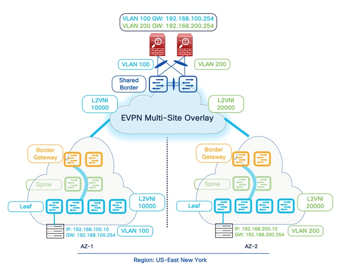
VXLAN Multi-Site: Special Considerations for Layer 3 Extensions
Nexus 9000 switches, using the Border Gateway (BGW) functionality, allows Layer 2 and Layer 3 DCI Extensions across multiple sites running VXLAN EVPN. The BGW performs VXLAN packet re-origination to represent itself as the next hop to reach an endpoint that is locally connected to the VXLAN fabric. Today, the commonly deployed Layer 3 extension service is the Inter-AS option (VRF Lite), where the BGW can terminate VXLAN traffic and advertise the site's local networks to the external domain using Native IP (IPv4, IPv6). However, we can still leverage a BGW's inbuilt functionality to extend Layer 3 services using VXLAN EVPN.
When we use BGWs to extend Layer 3 only or to have a Shared-Border architecture where the Shared-Borders are only running Layer 3 services, it becomes crucial to understand and enable specific configurations for end-to-end traffic flow.
Before we look into the special conditions, let’s first understand the native VXLAN EVPN data plane security.
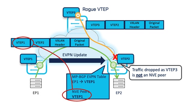
The VXLAN traffic originating from a remote VTEP is only accepted when sourced from a VTEP IP address that is an "NVE Peer." The NVE Peer's IP address is added to the local table based on the reception of EVPN updates carrying that specific IP address as the Next-Hop.
The following diagram shows a VXLAN EVPN fabric with two legitimate VTEPs and one rogue VTEP. An endpoint connected to VTEP-1 is being advertised as EVPN Type-2 (MAC and IP) to a remote VTEP. Therefore, VTEP-2 updates its NVE Peer table by listing the VTEP-1 IP address as a legitimate peer IP. At the same time, the rogue VTEP is trying to establish a VXLAN data plane tunnel towards VTEP-2, but as VTEP-2 does not recognize the VTEP-3 IP address in the NVE Peer list, it will drop the traffic. Hence, in the Nexus 9000 VTEP, we implement the SRC_TEP_MISS check for validating data plane security. This prevents the insertion of rogue VTEPs in a VXLAN EVPN fabric.
Now, let’s see what special considerations we must ensure to comply with the above implementation.
Inter-Site Layer 3 Traffic- Control Plane
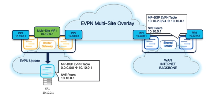
By default, the Inter-Site EVPN Type-2 (MAC only, MAC + IP) and Type-5 (Prefix) updates always carry the local Multi-Site VIP as the Next-Hop address. The exceptions are Type-5 updates for Layer 3 networks and prefixes locally connected to the BGWs.
It is important to note that Multi-Site VIP (Virtual IP address) only applies to devices running with Border Gateway (BGW) roles. Hence, the Shared-Border (Border role) does not carry the Multi-Site VIP. It instead uses a regular VTEP IP (typically Primary Lo1 in the case of a standalone Border, or Shared vPC secondary IP in the case of a vPC Border).
The following diagram shows that from the Control Plane perspective, the BGWs act as the next hop, and the appropriate NVE Peer IP list is also updated with the Multi-Site VIP.
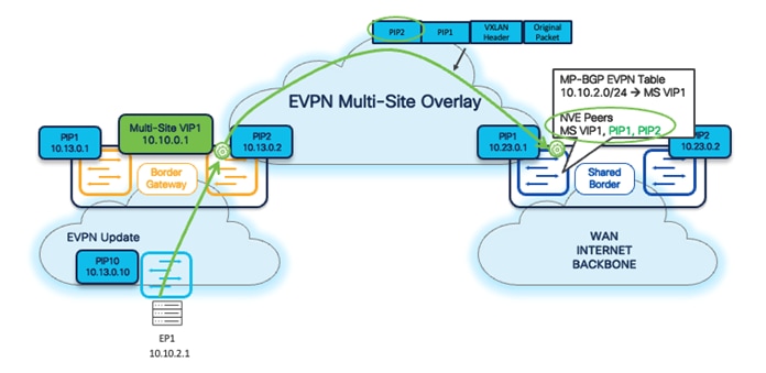
Inter-Site Layer 3 Traffic- Data Plane
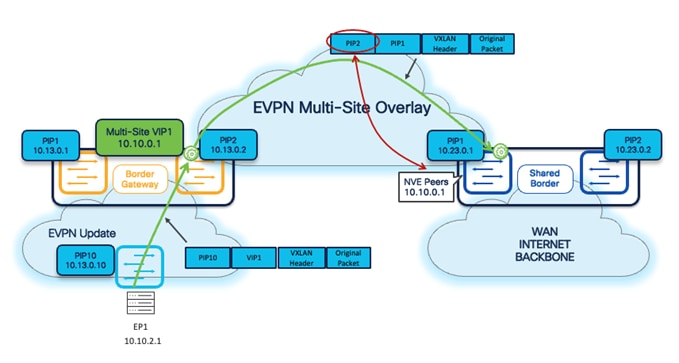
From a data plane point of view, the Inter-Site Layer 3 traffic is always sourced by the local BGWs using their specific PIP address. This also applies to Shared-Border architecture, where we extend Layer 3 services on the Border devices for North-to-South traffic.
As shown in the following diagram, the BGWs use the Outer SRC IP of the NVE IP address, while, by default, the Shared-Borders will only learn and form NVE Peering with the Multi-Site VIP of the BGWs. Hence, if a VXLAN packet comes to the Shared-Border with an Outer SRC IP address of the BGW, the packet will be dropped due to the SRC_TEP_MISS check.
To address the above situation in a Shared-Border architecture and deployments, the most common approach is to define and advertise a loopback in a Tenant-VRF (VXLAN VRF L3VNI) on every BGW, and then advertise to Shared-Borders as part of BGP EVPN updates. Once the EVPN update arrives at the Shared-Border, it will form the NVE Peering with the BGW Primary IP address.
Starting with NDFC release 12.1.3b, a new feature is introduced to simplify the configuration to address the special handling of Layer 3 communication between BGWs and Shared-Border. Following are the steps required to enable this feature:
Step 1. Navigate to the respective Data Center VXLAN EVPN fabric settings.
Step 2. Under the Resources tab, enable the flag for Per VRF Per VTEP Loopback Auto-Provisioning. Once the flag is enabled, NDFC proposes the IP subnet pool.
Step 3. Save the fabric setting and perform a Recalculate and Deploy.
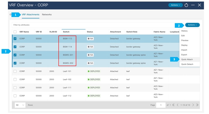
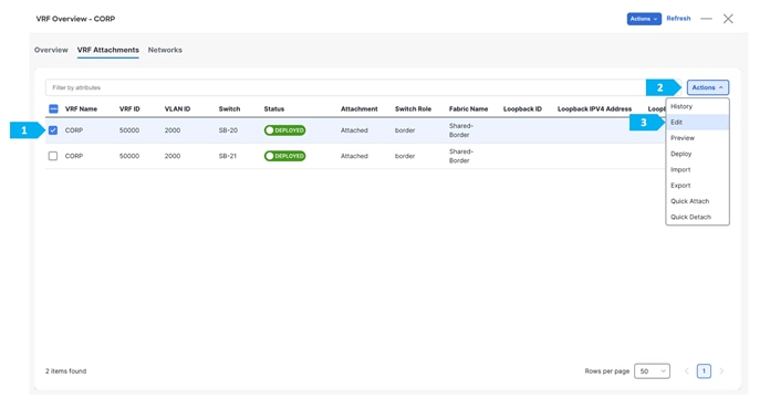
Step 4. Navigate to VRF Attachments and select the VRF.
Step 5. Click Actions > Quick Attach.
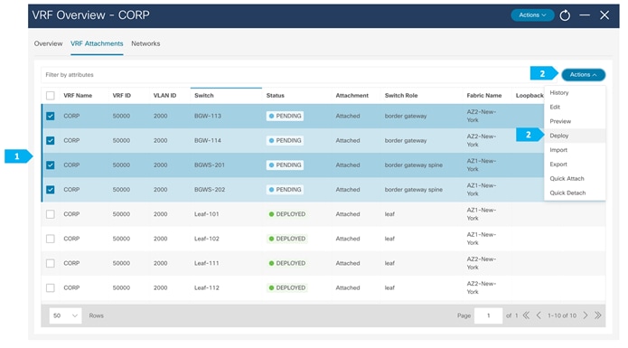
Step 6. Click Deploy.
Note: The VRF is already attached and deployed on the BGWs, but you must perform Quick Attach one more time for the Resource Manager to assign and allocate unique IP addresses on the devices.
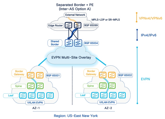
External Network IP Handoff Use-Cases
Typically, workloads often require communication with services outside of the Data Center domain in a Data Center fabric. This also includes users accessing applications and services from the Internet and WAN. The VXLAN EVPN Border devices are considered a handoff point for North-to-South communication. The Shared Border is a Site External VTEP to perform VXLAN EVPN to IP handoff. The Shared Border optimizes the traffic flows and reduces natural traffic hair-pinning. Also, it provides a deterministic handoff point in a VXLAN Multi-Site environment where multiple sites can rely on these Shared Borders to communicate with the External network such as WAN, Backbone, and Internet.
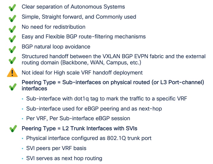
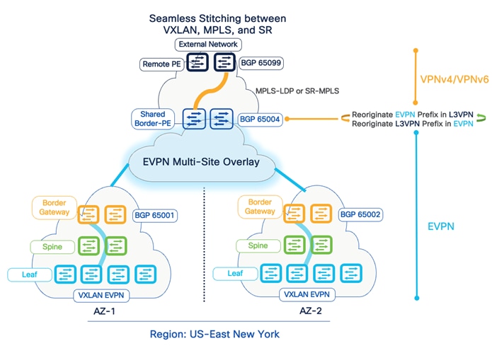
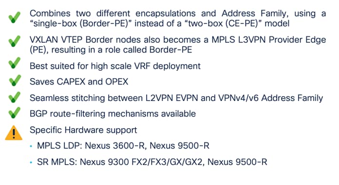
From the connectivity point of view, the Shared Borders supports Inter-AS option A (VRF Lite) and seamless VXLAN-MPLS gateway (Border-PE). Thus, a network admin can adopt different options based on the overall scale, configuration management, and operations.
Furthermore, NDFC fully supports the VRF Lite provisioning of Nexus and non-Nexus devices using a single plane of glass solution.


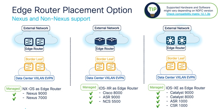
VRF Lite to External Edge Router
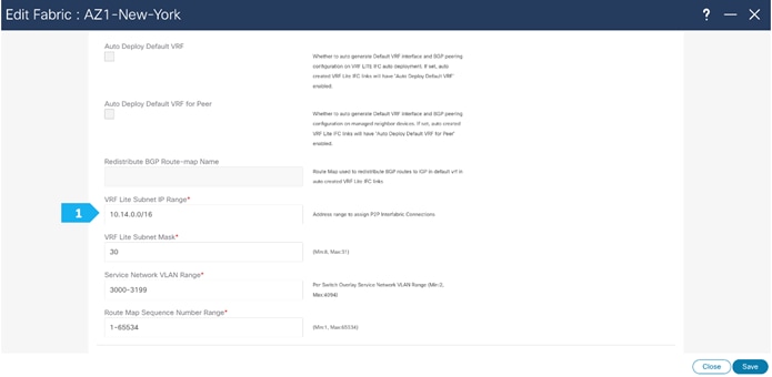
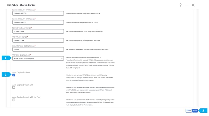
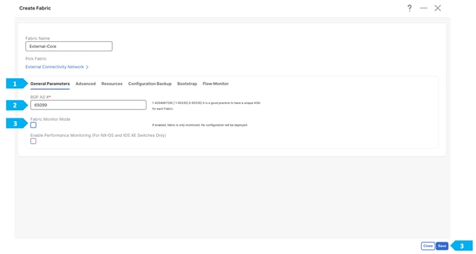
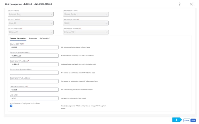
Step 1. Change the VRF Lite settings in Shared-Border Fabric
In this step, we will specify the VRF Lite method for extending inter fabric connections. The VRF Lite Subnet IP Range field specifies resources reserved for IP addresses used for VRF Lite when VRF Lite IFCs are auto created. When we select Back2Back&ToExternal, then VRF Lite IFCs are automatically created.
The Auto Deploy for Peer check box is applicable for VRF Lite deployments. When we select this checkbox, auto-created VRF Lite IFCs will have the Auto Generate Configuration for Peer field in the VRF Lite tab set.
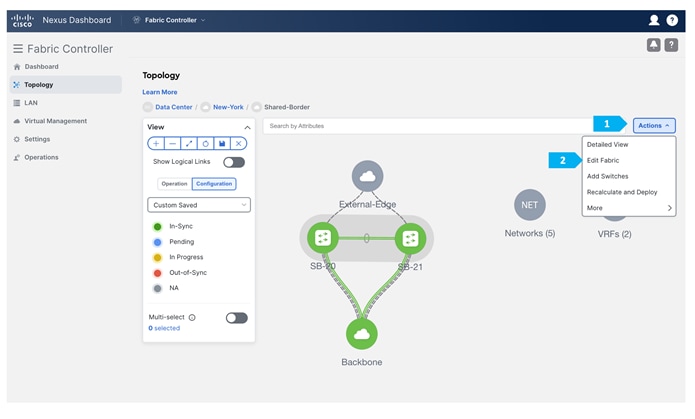
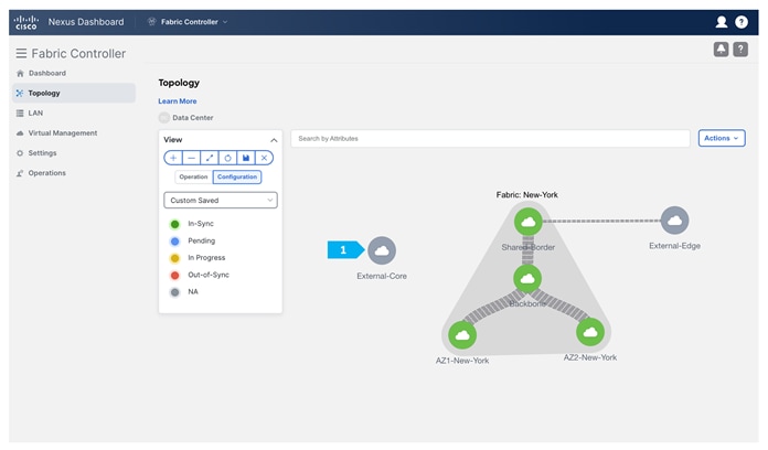
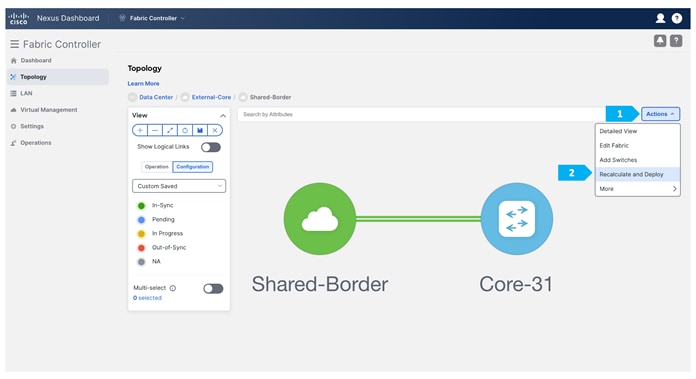
Step 2. Creating the External fabric and adding the devices
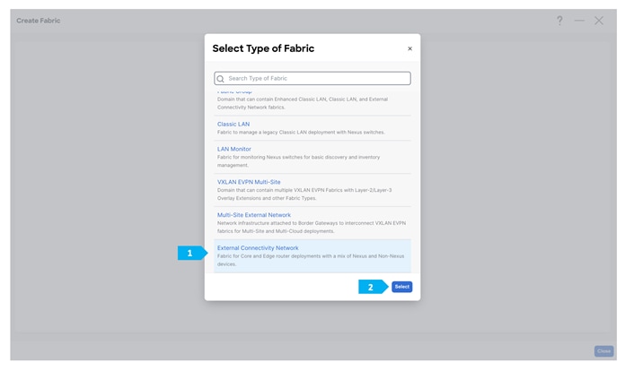
After clicking Save, double-click on the “External-Core” fabric.
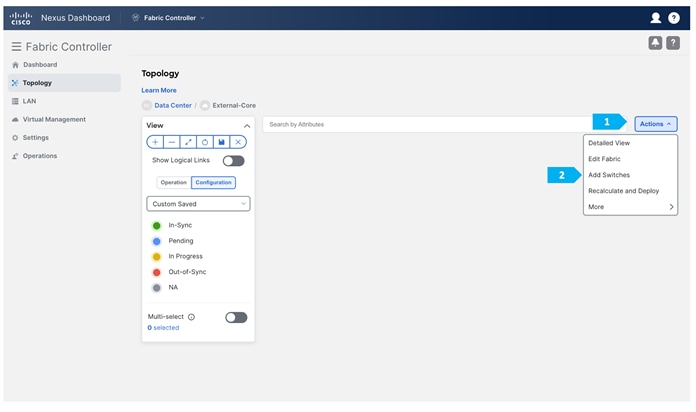
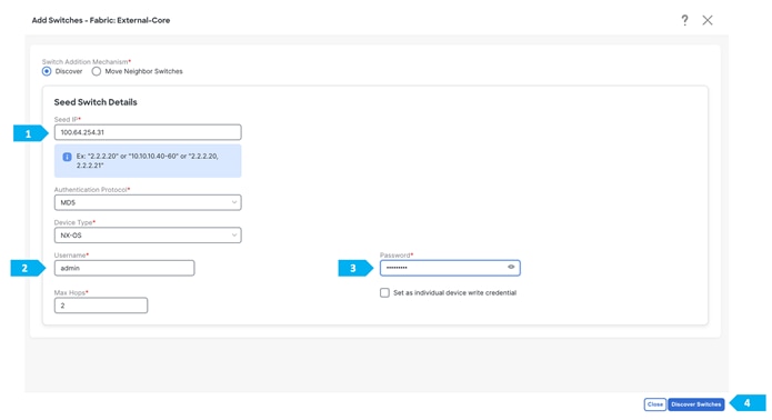
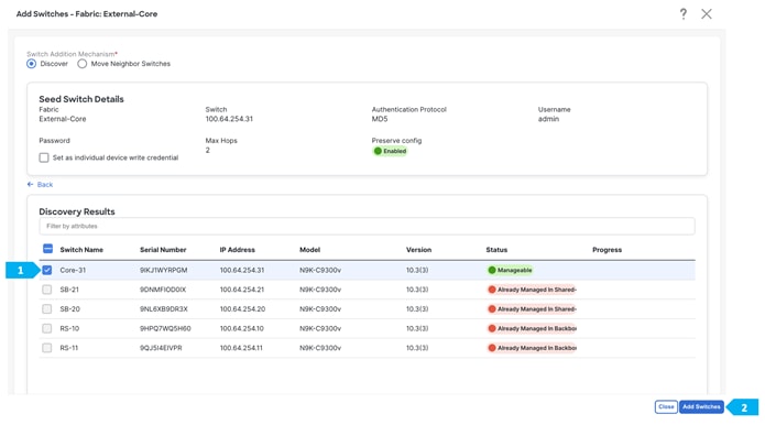
After clicking “Add Switches”, wait until the progress bar is green, then click Close.
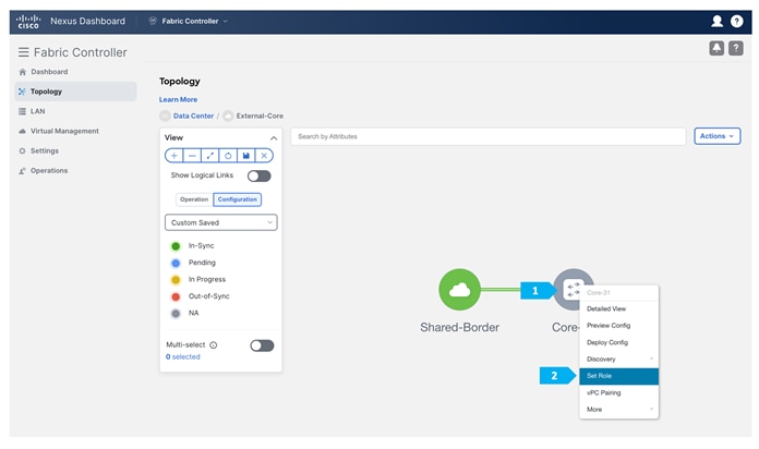
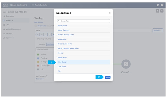
We will be using a Nexus device for this configuration, so right-click on “Core-31” and choose Set Role, then select “Edge Router” as the role for this device.
Step 3. Checking links between Shared-Borders and Edge Router
Double-click on the “Shared-Border” fabric.
The “Links” tab will show the Core-31-to-SB-20 link and the Core-31-to-SB-21 link, and the policy should be “ext_fabric_setup” as shown below. We can refine the search using “Policy contains ext_fabric_setup”.
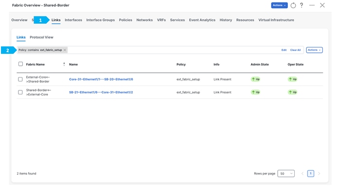
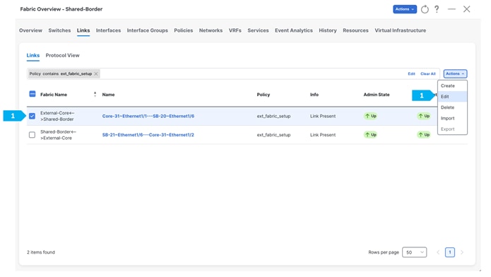
Repeat the same step for SB-21 to Core-31.
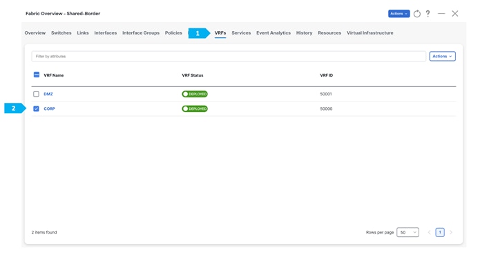
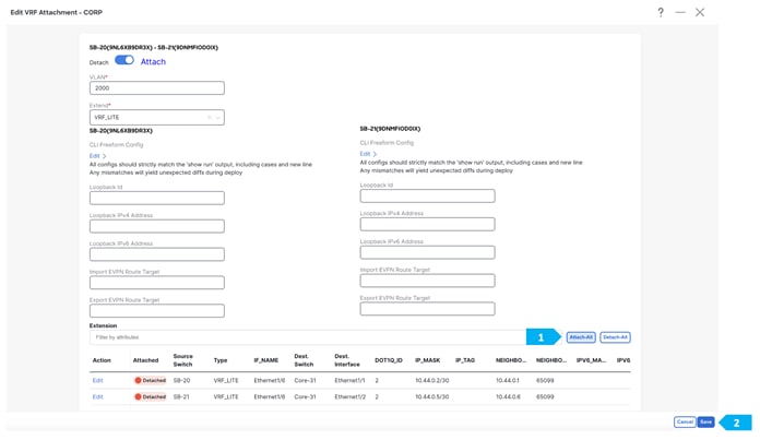
Step 4. Attach VRF Extension
Note: Before doing this step, please make sure that the interfaces between Shared borders SB-20, SB-21, and Core-31 are routed ports and not trunk ports.
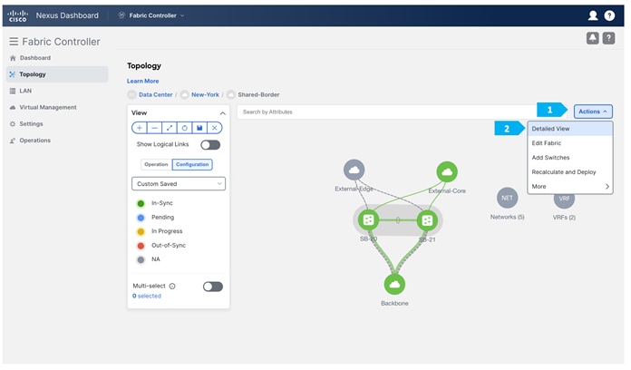
Go to the “VRF” tab and double-click on the “CORP” VRF.
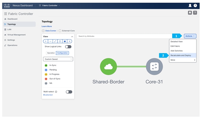
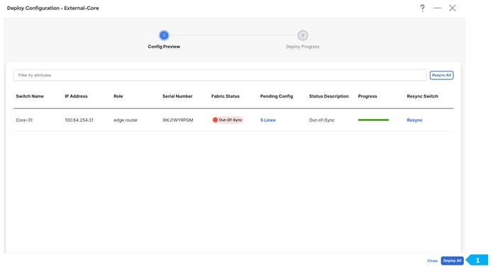
After we finish the deployment in the “Shared-Border” fabric, double-click on the “External-Core” fabric and perform a “Recalculate and Deploy”.
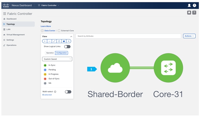
By now we have implemented VRF Lite between Shared-Border and External-Core for the CORP VRF.
Note: The VRF Lite deployment option shown above gives an example of one way to extend IP handoff services between VXLAN EVPN and external networks. The deployment of Shared-Borders can be Layer 3 independent devices (no vPC) or part of a vPC domain. By default, the Shared-Borders extend Layer 3 services across different routing domains. The VXLAN EVPN traffic behavior changes based on the deployment model. For example, Shared-Borders running as Layer 3 independent devices use its Primary VTEP IP as the BGP NH (next-hop) to advertise the Site-External prefixes to VXLAN EVPN fabrics. However, Shared-Borders that are part of a vPC domain will use the Secondary known as VIP VTEP IP as the BGP NH to advertise the Site-External prefixes to VXLAN EVPN fabrics.
To handle specific traffic and link failure scenarios, the following is recommended:
- Use “Advertise-PIP” of vPC Border devices when doing VXLAN EVPN to IP handoff. For more information, see:
- Starting with the NDFC 12.1.3b release, the “Advertise-PIP” option is enabled by default for vPC Border devices.
- In unique failure scenarios, such as a Zig-Zag failure where the Shared-Border-1 loses all of its links towards Edge and the Shared-Border-2 loses all of its links towards the VXLAN EVPN fabric, special considerations must be accounted for, such as the deployment of Layer 3 Underlay link across the Shared-Border for continuous connectivity across VXLAN EVPN and External IP networks, and a per-VRF iBGP session for handling locally attached EPs, service nodes, or external devices.
Service Node Peering Use-Cases
In earlier sections, we discussed how Shared-Border can be implemented in the vPC domain to connect with Layer 4 to Layer 7 service nodes, such as firewalls, load balancers, TCP Optimizers, and more.
While this document does not cover details about Layer 4 to Layer 7 design, best practices, and use cases, it is important to highlight two common use cases with Shared Border as follows:
Layer 2 Extension for DMZ:
Typically, data center applications such as SaaS and other critical customer-facing applications require Internet connectivity. In the data center, the network admin deploys a perimeter firewall for traffic inspection, especially for traffic traversing between untrust and trust zones. Therefore, service nodes such as firewalls host network gateway services for these applications. In such circumstances, the VXLAN EVPN fabric acts as a Layer 2 bridging domain between endpoint applications and the firewall.
In a Shared-Border architecture, the placement and connectivity of Layer 4 to Layer 7 services become crucial to avoid traffic hair pinning and to achieve deterministic traffic flows. When we have multiple Availability Zones (AZs), the Shared-Border becomes a natural choice to connect with the service nodes.
It is also important to note that Layer 2 BUM and bridging traffic must flow across these fabrics. The site/AZ-specific Border Gateway (BGW) is responsible for distributing the Layer 2 information of endpoints within and across the fabrics. At this time, Cisco NDFC supports Ingress-Replication (IR) as the replication method for DCI (VXLAN Multi-Site). The BGWs advertise EVPN Type-3 (IMET) routes to form an IR table with the L2VNI and the VTEP information. Therefore, we must ensure that Layer 2 VXLAN traffic arrives at the Shared Border to process and forward to the service nodes. Hence, the replication method for the Shared-Border fabric must be set to Ingress-Replication during the Day-0 fabric configuration using NDFC. From a configuration point of view, we must create and deploy Layer 2 only VNI across Leaf, BGW, Shared-Border, and the interface connecting between the Shared-Border and the service node.
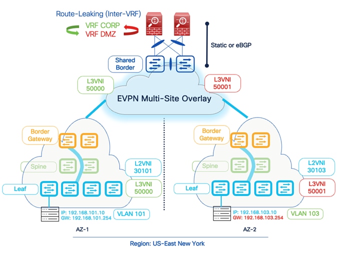
Inter-Tenant VRF (VRF Fusion)
Another popular use-case for firewall peering in a VXLAN EVPN environment is implementing Inter-Tenant VRF connectivity for Layer 3 communications across different VRFs. By default, a VRF signifies unique and separate control and data plane functionality on a VTEP. One of the advantages of the VXLAN EVPN environment is to achieve Secure Multi-Tenancy and Mobility at scale. Hence, if an endpoint is part of VRF X, the same endpoint can’t communicate with another endpoint that is part of VRF Y.
Due to different data center use cases such as migration, mergers, and inter-domain connectivity, traffic is expected to leak across other tenants. While various methods such as EVPN RT import/export, Downstream VNI, and Centralized Route Leaking are available to perform the route leaking on Cisco Nexus 9000 and NX-OS devices, one of the other standard methods is to rely on an external service node to inspect and perform these additional functionalities.
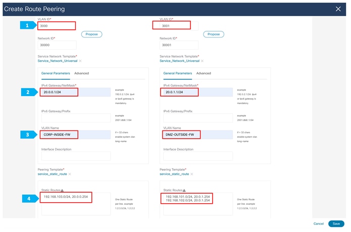
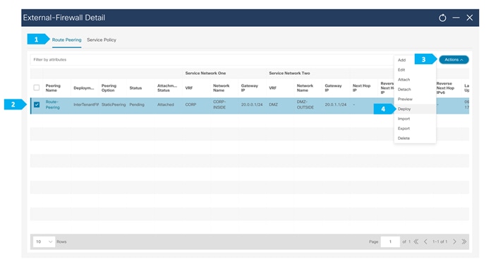
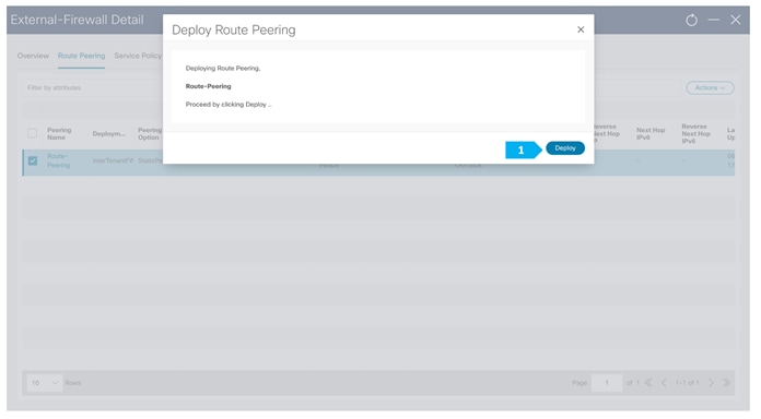
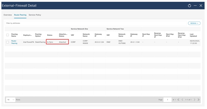
Therefore, a service node such as a firewall acts as a fusion stitching point to enable communication between VRF X and VRF Y. From a configuration point of view, Cisco NDFC supports static routing or dynamic routing using BGP between the Shared-Border and the service node. The example in this document is based on static routing, but the same can be implemented using BGP.
In this example, we need to connect the firewall to SB-20 and SB-21 using vPC.
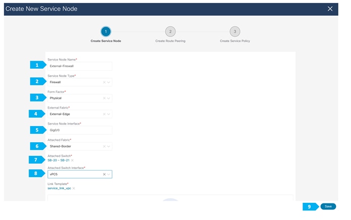
We must create an external fabric and specify that a service node resides in that external fabric during the service node creation. NDFC does not auto-detect or discover any service nodes. We must also specify the service node name, type, and form factor. The name of the service node must be unique within a fabric. NDFC does not define a new switch role for a service node.
NDFC manages the switches that are attached to a service node. It also manages the interfaces of these attached switches. Ensure that the interfaces that the service node is attached to are in trunk mode and do not belong to any Interface Group. When the attached switches are forming a vPC pair, the name of the attached switch is a combination of both switches.
Note: Navigate to Data Center VXLAN EVPN fabric overview (in our case Shared-Border) and the Services tab to make these configurations.
We will need to enter information for the inside network and the outside network.
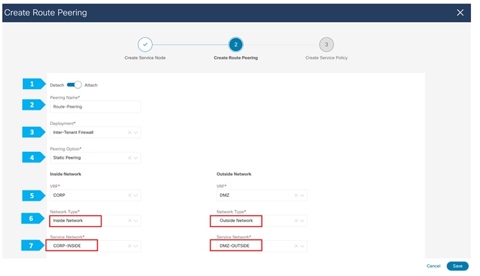
Note: We need to type the name in the Network Type field.
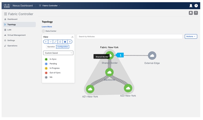
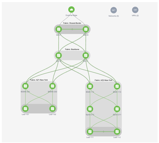
Final NDFC Topology
Conclusion
Shared-Border, which is a site external VTEP, interconnects VXLAN EVPN Multi-Site domains to provide a deterministic connectivity point for Layer 3 IP services and handoff. Flexbile deployment models and architecture of Shared-Border allows a network admin to optimize Layer 2 and Layer 3 DCI traffic flows by interconnecting various Availability Zones and extending the connectivity to shared services.
Additional Information
Configuration Guides and White Papers
https://www.cisco.com/c/en/us/products/switches/nexus-9000-series-switches/white-paper-listing.html