Cisco Nexus 9300-H Series Switches White Paper
Available Languages
Bias-Free Language
The documentation set for this product strives to use bias-free language. For the purposes of this documentation set, bias-free is defined as language that does not imply discrimination based on age, disability, gender, racial identity, ethnic identity, sexual orientation, socioeconomic status, and intersectionality. Exceptions may be present in the documentation due to language that is hardcoded in the user interfaces of the product software, language used based on RFP documentation, or language that is used by a referenced third-party product. Learn more about how Cisco is using Inclusive Language.
- US/Canada 800-553-2447
- Worldwide Support Phone Numbers
- All Tools
 Feedback
 Feedback
Cisco CloudScale LS12800H2R and LS6400H1 ASIC Architecture
CloudScale LS12800H2R and LS6400H1 ASIC Overview
CloudScale H2R/H1 ASIC Slice Forwarding Path
CloudScale H2R/H1 ASIC Ingress Forwarding Controller
CloudScale H2R/H1 ASIC Egress Forwarding Controller
Cisco CloudScale H2R and H1 ASIC Forwarding lookup
CloudScale H2R/H1 ASIC Forwarding TCAM
CloudScale H2R/H1 ASIC Flexible forwarding Tiles (flex tiles)
CloudScale H2R/H1 ASIC Unicast Forwarding
CloudScale H2R/H1 ASIC Multicast Forwarding
CloudScale H2R/H1 ASIC VXLAN Forwarding
Cisco CloudScale H2R and H1 ASIC Clasification TCAM
CloudScale H2R/H1 ASIC TCAM Scalability
CloudScale H2R/H1 ASIC Default ACL TCAM Allocation
CloudScale H2R/H1 ASIC Egress RACL Example
Cisco CloudScale H2R and H1ASIC Hardware Telemetry
CloudScale H2R/H1 ASIC Flow Table (FT), Flow Table Event (FTE) and Netflow
CloudScale H2R/H1 ASIC Inband Network Telemetry (INT)
CloudScale H2R/H1 Streaming Statistics Export (SSX)
Cisco CloudScale H2R and H1 Span on Drop (SOD)
CloudScale H2R/H1 ASIC Ingress Forwarding Drop
CloudScale H2R/H1 ASIC Egress Buffer Drop
CloudScale H2R/H1 ASIC Egress Rewrite Engine Drop
CloudScale H2R/H1 ASIC Packet Recirculation
Cisco CloudScale H2R and H1 ASIC Packet Buffer
CloudScale H2R/H1 ASIC On-Die packet Buffer
CloudScale H2R/H1 ASIC Intelligent Buffering
CloudScale H2R HBM Packet Buffer
Cisco CloudScale H2R and H1 ASIC AI/ML
Explicit Congestion Notification (ECN)
Nexus 9300-H MACsec Hardware Encryption
In 2016, Cisco made its debut of the Cisco Nexus® 9000 Series Switch line with products built on the revolutionary Cisco® CloudScale intelligent Application-Specific Integrated Circuits (ASICs). These initial CloudScale platforms enabled customers to establish high-performance, cost-effective data center networks, offering a transition from 10G and 40G Ethernet to more robust 25G and 100G connectivity options. Over the following years, Cisco continued to expand and enhance the product family with additional platforms, introducing numerous innovations to address the evolving demands of CloudScale data centers, converged and hyperconverged infrastructure, and virtualized and containerized applications.
Large-cloud and data center networking teams require a flexible, reliable solution that efficiently manages, troubleshoots, and analyzes their IT infrastructure. In addition, they need security, automation, visibility, analytics, and assurance. Coupled with tools such as Cisco Nexus Dashboard Insights for visibility and Nexus Dashboard Fabric Controller for automation, Cisco Nexus 9300 Series switches are ideal platforms to build a high-performance artificial intelligence/machine learning (AI/ML) network fabric.
The inclusion of 400G Ethernet technology further enriches the CloudScale portfolio by providing platforms that deliver high-density, leaf switch (top-of-rack) aggregation, spine switch aggregation, and backbone connectivity options. These platforms utilize the GX, GX2A, and GX2B switches, plus the latest additions: H2R and H1 CloudScale ASICs. With 400G options available for both top-of-rack and modular systems, the Nexus 9000 series chassis stand at the forefront of the industry, incorporating innovations such as 400G QSFP-DD (double density) transceivers that offer full backward compatibility with existing QSFP28 (100G) and QSFP+ (40G) transceivers.
This comprehensive document provides an in-depth explanation of Cisco CloudScale LS12800H2R and LS6400H1 ASICs utilized in Cisco Nexus 9300-H2R and 9300-H1 platforms. The primary aim of this document is to highlight the latest feature enhancements with the CloudScale ASICs.
This document is for planning, implementation, and maintenance in DevOps teams.
The Cisco Nexus 9000 platform switches are equipped with cutting edge Cisco Custom CloudScale technology ASICs. This unique approach of designing and owning both the silicon, software SDK, and operating system confers significant competitive advantages to the Nexus 9000 series. It serves as a powerful vehicle for delivering an array of advanced features and functions.
Leveraging the advantages of the latest semiconductor device fabrication, these ASICs boast higher transistor density and lower power consumption. These features are crucial in enabling the creation of ASICs with increased bandwidth, a higher number of ports, larger forwarding tables, generous buffers, and the opportunity to implement novel, advanced capabilities.
Cisco's cloud-scale ASICs introduce a wide range of Ethernet speeds, including 25, 50, 100, 200, and 400 Gigabit Ethernet (GE), to data center networks at a cost point optimized for optimal performance. See Table 1 for the specific CloudScale ASICs used in each Cisco Nexus 9000 switch family. Table 2 highlights the major feature sets associated with each CloudScale ASIC.
Table 1. Cisco CloudScale ASIC family with their corresponding Nexus 9000 switch
| CloudScale ASIC |
Nexus 9000 Family |
Platforms and Line Cards |
| LS 1800 EX |
9300-EX, X9700-EX (LCs) |
C93180YC-EX, C93108TC-EX, C93180LC-EX, X9732C-EX, X9736C-EX, X97160YC-EX |
| LS 1800 FX |
9300-FX, X9700-FX (LCs) |
C93180YC-FX, C93108TC-FX, C9348GC-FXP, X9732C-FX, X9736C-FX, X9788TC-FX |
| LS 3600 FX2 |
9300-FX2 |
C9336C-FX2, C9336C-FX2-E, C93240YC-FX2, C93360YC-FX2, C93216TC-FX2 |
| LS 1800 FX3 |
9300-FX3 |
C93180YC-FX3, 93180YC-FX3S, C93108TC-FX3P, C93108TC-FX3, C9348GC-FX3, C9348GC-FX3PH |
| S 6400 |
9300C, FM-E2 (FMs) |
9364C, 9332C, 9508-FM-E2, 9516-FM-E2 |
| LS 6400 GX |
9300-GX, X9700-GX (LCs) |
C9316D-GX, C93600CD-GX, C9364C-GX, X9716D-GX, 9504-FM-G, 9508-FM-G |
| LS 25600 GX2A LS 12800 GX2B |
9300-GX2A, 9300-GX2B, 9408 |
9364D-GX2A, 9348D-GX2A, 9332D-GX2B, C9400-SW-GX2A |
| LS 12800 H2R LS 6400 H1 |
9300-H2R, 9300-H1 |
9332D-H2R, 9364C-H1, C93400LD-H1 |
Table 2. Cisco CloudScale ASIC family features
| ASIC Feature |
LS 1800 EX |
LS 1800 FX |
LS 3600 FX2 |
LS 1800 FX3 |
S 6400 |
LS 6400 GX |
LS25600 GX2A |
LS12800 GX2B |
LS12800 H2R |
LS6400 H1 |
| Bandwidth (Tbps) |
1.8T |
1.8T |
3.6T |
1.8T |
6.4T |
6.4T |
25.6T |
12.8T |
12.8T |
6.4T |
| No. of Slices |
2 Slices |
1 Slice |
2 Slices |
1 Slice |
4 Slices |
4 Slices |
8 Slices |
4 Slices |
4 Slices |
2 Slices |
| Fabrication Node |
16nm |
16nm |
16nm |
14nm |
16nm |
14nm |
7nm |
7nm |
7nm |
7nm |
| Max Ports (400/200/ 100/50 GE) |
0/0/ 18/72 |
0/0/ 18/72 |
0/0/ 36/72 |
0/0/ 18/72 |
0/0/ 64/0 |
16/32/ 64/128 |
64/128/ 256/256 |
32/64/ 128/128 |
32/64/ 128/128 |
16/32/ 64/128 |
| Buffer/Max-per-port (MB) |
37.4/18.7 |
40/40 |
40/30 |
40/40 |
40/10 |
80/20 |
120/30 |
120/60 |
80/40 |
40/40 |
| HBM Packet Buffer |
N/A |
N/A |
N/A |
N/A |
N/A |
N/A |
N/A |
N/A |
8G HBM |
N/A |
| Telemetry |
FT
|
FT, FTE |
FT, FTE, SSX |
FT, FTE, SSX |
SSX |
FT, FTE, SSX, INT-XD, INT-Transparent |
FT, FTE, SSX, INT-XD |
FT, FTE, SSX, INT-XD |
FT, FTE, SSX, INT-MX, INT-MD, INT-XD |
FT, FTE, SSX, INT-MX, INT-MD, INT-XD |
| Hardware Entries/Tiles |
544K/17 |
1088K/34 |
544K/17 |
1088K/34 |
352K/11 |
1088K/34 |
640K/20 |
1280K/40 |
1280K/40 |
1280K/40 |
| Classification TCAM (Ingress/ |
4K/2K |
5K/2K |
5K/2K |
5K/2K |
4K/2K |
5K/2K |
6K/3K |
6K/3K |
14K Shared |
14K Shared |
Cisco CloudScale LS12800H2R and LS6400H1 ASIC Architecture
CloudScale LS12800H2R and LS6400H1 ASIC Overview
LS12800H2R and LS6400H1 are the latest additions to the Cisco CloudScale ASIC family with multiple enhancements to the previous CloudScale ASICs. The LS12800H2R comes with dual die, 4 network slices, and High Bandwidth Memory (HBM), while the LS6400H1has a single die with 2 slices. We will refer to them as H2R and H1 ASICs in the rest of this document. Figure 1 illustrates the H2R and H1 ASICs.
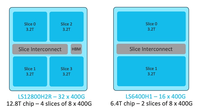
Figure 1. Cisco CloudScale LS2800H2R and LS6400H1 ASICs
A CloudScale ASIC slice refers to a self-contained forwarding complex responsible for handling both ingress and egress functions for a specific subset of ports. Each slice is further divided into separate sections for ingress and egress functions. The ingress portion of each slice is interconnected to all egress portions of other slices by way of a slice interconnect, which enables non-blocking any-to-any interconnection between slices. Figure 2 shows a visual representation of the Cisco CloudScale ASIC slice architecture.
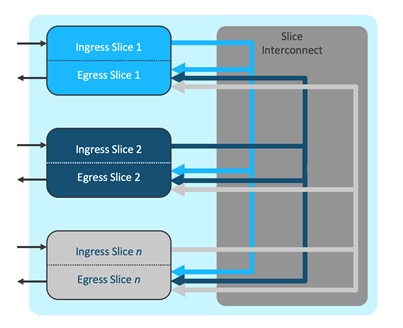
Figure 2 Cisco CloudScale H2R/H1 ASIC slice architecture
CloudScale H2R/H1 ASIC Slice Forwarding Path
Each of the pipeline elements shown in Figure 2 can consist of multiple forwarding processing steps. Figure 3 illustrates the detailed steps in the CloudScale ASIC pipelines.
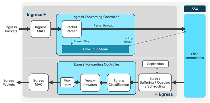
Figure 3 Cisco CloudScale H2R/H1 ASIC slice forwarding path
CloudScale H2R/H1 ASIC Ingress Forwarding Controller
The ingress forwarding controller operates as follows: when a packet is received from the MAC layer, it parses the packet headers and conducts several lookups to determine whether the packet should be accepted and how it should be forwarded to its intended destination. Additionally, the controller generates instructions for the data path to handle the storage and queuing of the packet. Figure 4 shows a visual representation of this process, showcasing the CloudScale ASIC ingress forwarding controller.
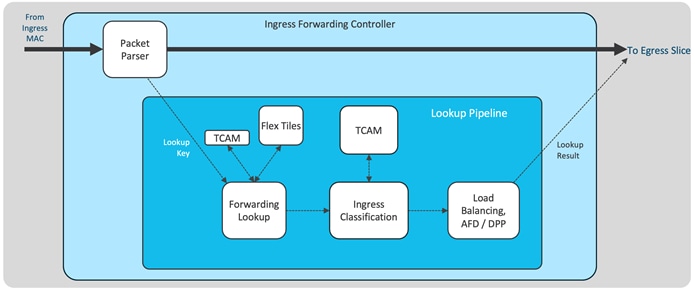
Figure 4 Cisco CloudScale H2R/H1 ASIC ingress forwarding controller
CloudScale H2R/H1 ASIC Egress Forwarding Controller
The egress forwarding controller is tasked with receiving packets from the buffer manager, along with their corresponding metadata, for transmission purposes. Its primary responsibilities include egress classification and managing all packet rewrites. Figure 5 shows the representation of the egress forwarding controller, which is where the egress classification takes place. Egress RACLs and VACLs are the most commonly allocated TCAM resources for egress classification. Additionally, egress PACLs are also supported with H2R and H1 ASICs.
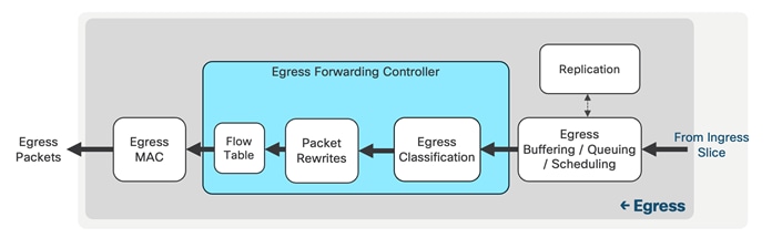
Figure 5 Cisco CloudScale H2R/H1 ASIC egress forwarding controller
Cisco CloudScale H2R and H1 ASIC Forwarding Lookup
The forwarding lookup is the initial block in the forwarding pipeline. It comprises two components: the forwarding TCAM and Flexible tiles. It is important to note that the forwarding TCAM is not utilized for classification ACLs; instead, a separate resource, the ACL/QoS TCAM, is used for this purpose. The H2R/H1 forwarding lookup block is depicted in Figure 6.
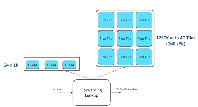
Figure 6 Cisco CloudScale H2R/H1 ASIC forwarding lookup blocks
CloudScale H2R/H1 ASIC Forwarding TCAM
The forwarding TCAM, a conventional TCAM memory, manages overflow and hash collisions, serving as the front-end for flexible forwarding lookups. The H2R and H1 ASICs feature a 24K forwarding TCAM divided into smaller 1K banks. The default allocation of the forwarding TCAM is illustrated in Figure 7. By default, ten 1K banks are assigned to IPv4, and twelve 1K banks are allocated to IPv6. When Unicast Reverse Path Forwarding (uRPF) is activated on the Nexus 9300-H, these entries are shared with uRPF.
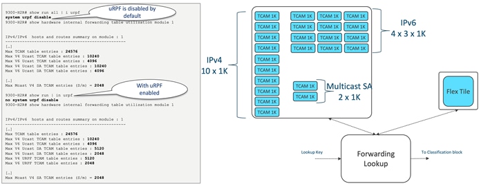
Figure 7 Cisco CloudScale H2R/H1 ASIC Forwarding TCAM banks
CloudScale H2R/H1 ASIC Flexible forwarding Tiles (flex tiles)
The flexible tiles serve as the second component of the forwarding lookup. They offer a versatile pool of table entries for lookups, capable of performing a variety of functions, including:
● IPv4/IPv6 unicast longest-prefix match (LPM)
● IPv4/IPv6 unicast host-route table (HRT)
● IPv4/IPv6 multicast (*,G) and (S,G)
● MAC address table/adjacency table
● ECMP tables
● ACI policy
Figure 8 illustrates the flexible tiles component within the forwarding lookup block.
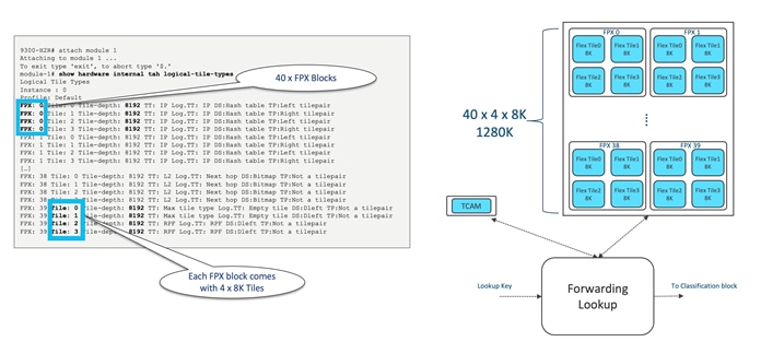
Figure 8 Cisco CloudScale H2R/H1 ASIC “flexible tiles”
Both the H2R and H1 ASICs feature a total of 160 x 8K tiles, which can be restructured using the "system routing template" command. Figure 9 shows how users can alter the default template, while Table 3 presents the supported forwarding templates for the H2R and H1 ASICs, including the scalability of each profile. Refer to the Nexus 9000 Verified Scalability Guide (VSG) for additional information on scalability.
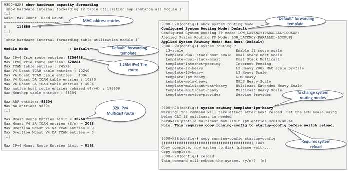
Figure 9 Cisco CloudScale H2R/H1 ASIC Hardware forwarding templates
Table 3 Cisco CloudScale H2R/H1 ASIC forwarding templates
| Template |
MAC |
IPv4 Trie |
IPv6 Trie |
IPv4 TCAM |
IPv6 TCAM |
IPv4/IPv6 Host |
Nexthop Table entries |
ARP/ND |
IPv4 Multicast |
IPv4 Multicast SA |
IPv6 Multicast |
|
| Default |
114,688 |
1,256,448 |
628,224 |
10,240 |
4,096 |
196,608 |
98,304 |
98,304 |
32,768 |
2,048 |
8,192 |
|
| L2 Heavy |
262,144 |
1,256,448 |
628,224 |
10,240 |
4,096 |
196,608 |
253,952 |
98,304 |
0 |
2,048 |
0 |
|
| Dual Stack Host Scale |
114,688 |
419,430 |
235,929 |
10,240 |
4,096 |
393,216 |
131,072 |
98,304 |
32,768 |
2,048 |
8,192 |
|
| Internet Peering |
32,768 |
2,000,000 |
628,224 |
10,240 |
4,096 |
114,688 |
49,152 |
49,152 |
0 |
2,048 |
0 |
|
| LPM Heavy |
114,688 |
1,256,448 |
628,224 |
10,240 |
4,096 |
196,608 |
98,304 |
98,304 |
8,192 |
2,048 |
2,048 |
|
| MPLS Heavy |
98,304 |
681,574 |
383,385 |
10,240 |
4,096 |
196,608 |
196,608 |
98,304 |
0 |
2,048 |
0 |
|
| Multicast Heavy |
49,152 |
1,256,448 |
628,224 |
9,216 |
4,096 |
327,680 |
65,536 |
65,536 |
32,768 |
1,024 |
8,192 |
|
| Multicast-Ext-Heavy |
57,344 |
1,256,448 |
628,224 |
9,216 |
4,096 |
327,680 |
65,536 |
65,536 |
131,072 |
1,024 |
8,192 |
|
CloudScale H2R/H1 ASIC Unicast Forwarding
After the forwarding template configures the flexible tiles, the H2R/H1 ASIC conducts hardware lookups based on the packet type. Specifically, for IP unicast packets, the lookup key comprises the virtual routing and forwarding (VRF) and the IP destination address derived from the packet.
At the same time, the ASIC accesses two distinct tables to find the longest prefix match for the packet's IP address. The first table, the host route table (HRT), includes exact match entries for locally learned /32 or /128 host addresses. Through a hash-based lookup, the ASIC verifies if there's an existing entry for the specific IP address. If such an entry is present, it signifies the longest prefix match.
In parallel, the ASIC conducts a lookup in the longest prefix match (LPM) table. This table permits variable-length prefix matching, enabling the matching of IP prefixes such as /24 or /16. The ASIC identifies which of the two tables has the longest match.
After the longest prefix match is established, the ASIC moves on to verify if there are multiple paths to the destination address. The destination address could be linked with a single interface or multiple next hops.
If the destination is directly connected and not a multi-path entry, the ASIC fetches an adjacency pointer from the table. This pointer holds information about reaching the next hop, including the output interface, the new destination MAC address (if crossing a Layer 3 boundary), and the MTU.
For multi-path entries, the ASIC consults an equal-cost multipath (ECMP) or load balancing table to choose the suitable next hop from the available options. The ASIC determines which path to select, and the chosen path is assigned an adjacency pointer. Both IPv4 and IPv6 unicast packets undergo these processes. The IP Unicast lookup process is depicted in Figure 10.
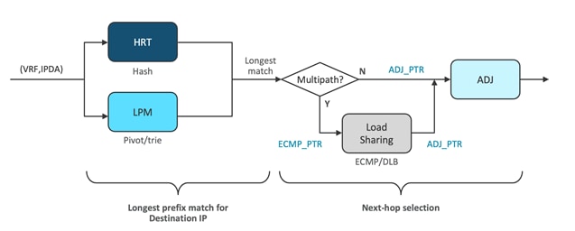
Figure 10 Cisco CloudScale H2R/H1 ASIC unicast forwarding
CloudScale H2R/H1 ASIC Multicast Forwarding
The process varies slightly when handling multicast packets. An exact match lookup is conducted in the host route table (HRT), involving the VRF instance, IP source address, and IP destination address. These lookups aim to identify mroute entries by matching the source and destination group IP addresses in the packet. The objective is to discern whether the mroute is a specific (S,G) or shared tree (star,G) entry.
If a match is detected in the HRT, the system refers to a separate table known as MC info. This additional table, implemented using flex tiles, holds information like the reverse path forwarding (RFP) interface and the multicast expansion table (MET) pointer. In multicast, an RPF check is necessary for each packet to ensure that we are not creating a loop. If a packet arrives from a non-RPF interface, it will be dropped to prevent looping.
Assuming the RPF check passes, a MET pointer is acquired. The MET table is found at the egress side of the slice. When the packet reaches the egress side (as seen in the packet walk), the MET table decides the number of packet copies required based on the outgoing interface list (OIL). The OIL designates the interfaces where the multicast packet should be duplicated.
Overall, this process guarantees efficient multicast forwarding, averting loops and determining suitable replication of multicast packets based on the mroute entries and OIL. Figure 11 illustrates the multicast lookup process.
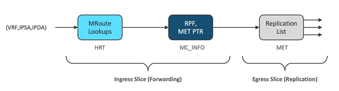
Figure 11 Cisco CloudScale H2R/H1 ASIC multicast forwarding
CloudScale H2R/H1 ASIC VXLAN Forwarding
VXLAN and other tunnel encapsulation/ decapsulation performed in single pass with Cisco CloudScale H2R/H1 ASIC.
In the ingress direction, the adjacency signifies the existence of a tunnel. This tunnel initiates a rewrite function for the outer header, including MAC and IP addresses. The actual rewrite operation takes place during the data processing's egress phase. When a packet enters the H2R/H1 ASIC, it scrutinizes the inner packet to determine if it is destined for a tunnel. The ASIC then chooses the appropriate tunnel and appends the necessary information to the packet, such as the outer source MAC address and VXLAN VNID.
On the other hand, in the reverse direction, after the packets have been subjected to lookup processes, the parser recognizes them as tunnel packets. It captures both the inner and outer packet header fields. The ASIC's tunnel endpoint (TEP) table is consulted to ascertain whether the outer header's destination address corresponds to a local tunnel within the switch. If it does, additional lookup operations are performed on the inner header. If it does not match a local tunnel, the packet is forwarded based solely on the outer header. For packets destined for local tunnels, packet termination is required. This process involves conducting inner Layer 2/Layer 3 lookups and, if necessary, the rewrite block removes the VXLAN encapsulation and makes any necessary adjustments to the original inner frame before forwarding it. Figure 12 depicts both the encapsulation and decapsulation steps.
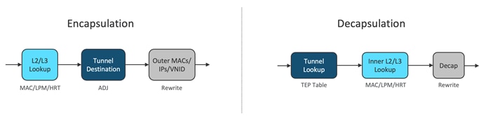
Figure 12 Cisco CloudScale H2R/H1 ASIC VXLAN forwarding
Cisco CloudScale H2R and H1 ASIC Classification TCAM
Following forwarding lookups, the packet proceeds to ingress classification processing. The ingress matches are checked against the classification TCAM. These ACLs include various types such as routed ACLs (RACLs), VLAN ACLs (VACLs), port ACLs (PACLs), Quality of Service (QoS), network address translation (NAT) ACLs, and more.
The classification entries are restricted to individual ASIC slices and are programmed only where needed. This method enhances the utilization of the classification TCAM in the Cisco Nexus 9300-H platform switches. The H2R and H1 ASICs share a 14K TCAM space, which caters to both ingress and egress classifications. The Cisco CloudScale H2R/H1 classification TCAM architecture is demonstrated in Figure 13.
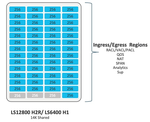
Figure 13 Cisco CloudScale H2R/H1 ASIC ACL TCAM architecture
CloudScale H2R/H1 ASIC TCAM Scalability
The CloudScale H2R/H1 ASIC TCAM is optimized for scalability through slice-aware policy programming. PACL and RACLs are programmed only on slices where ports with these ACLs are present, and port channel ACLs are programmed solely on slices where the respective members exist. Similarly, VLAN ACLs are programmed exclusively on slices where the corresponding VLAN is present. To enable policy sharing, labels are used with label space localized to each slice. For Cisco CloudScale H2R/H1 ASIC ACL TCAM scalability numbers, see Table 4. It is important to note that the TCAM scalability numbers were verified with all TCAM regions freed up except for the 'ing-sup' and 'egr-sup' regions.
Table 4 Cisco CloudScale H2R/H1 ASIC ACL TCAM scalability numbers
| ASIC |
Ingress PACL |
Egress PACL |
Ingress RACL |
Egress RACL |
Ingress VACL |
Egress VACL |
||||||
| Name/Slices |
Per Slice |
Total |
Per Slice |
Total |
Per Slice |
Total |
Per Slice |
Total |
Per Slice |
Total |
Per Slice |
Total |
| LS12800 H2R (4 slices) |
13568 |
54272 |
13568 |
54272 |
13568 |
54272 |
13568 |
54272 |
13568 |
54272 |
13568 |
54272 |
| LS6400 H1 (2 slices) |
13568 |
27136 |
13568 |
27136 |
13568 |
27136 |
13568 |
27136 |
13568 |
27136 |
13568 |
27136 |
CloudScale H2R/H1 ASIC Default ACL TCAM Allocation
The allocation of both ingress and egress ACL TCAM to different ACL types is user configurable. Each ACL type requires its dedicated bank/banks, and ACL programming is localized on a per ASIC basis. ACL entries are programmed into the TCAM only where they are required. By default, all available TCAM regions are allocated.
For the Cisco Nexus 9300-H2R and 9300-H1, they are the only Nexus platforms featuring shared TCAM space for both Ingress and Egress slices. By default, 10K is assigned for ingress and 4K for egress, but any bank can be reconfigured to serve either as ingress or egress.
To visualize the default classification TCAM regions for the Nexus 9300-H2R/H1 series switches, refer to Figure 14.
Figure 14 Default classification TCAM regions for Cisco Nexus 9300-H2R/H1 chassis
CloudScale H2R/H1 ASIC Egress RACL Example
The H2R and H1 ASIC offers the greatest number of TCAM entries for both Ingress and Egress regions. The maximum Egress RACL allocation with H2R/H1 ASICs is illustrated in the example shown in Figure 15. To achieve the maximum Egress RACL, the user must first deallocate the default regions.
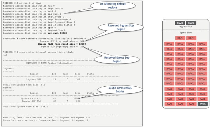
Figure 15 Maximum Egress RACL allocation with Nexus 9300-H2R/H1 chassis
Cisco CloudScale H2R and H1ASIC Hardware Telemetry
Besides Software Telemetry, Cisco H2R and H1 ASICs also incorporate Hardware Telemetry, further divided into two primary components. These components include data plane flow data, obtained from the actual traffic moving through the forwarding pipeline, and basic ASIC data. The latter signifies statistics that can be extracted from the ASIC at remarkably high rates. These telemetry features are visually represented in Figure 16. It should be noted that Cisco Nexus Dashboard Insight (NDI) currently uses flow table (FT), flow table events (FTE), and streaming statistics (SSX). Furthermore, there is no software support available for in-band network telemetry (INT).
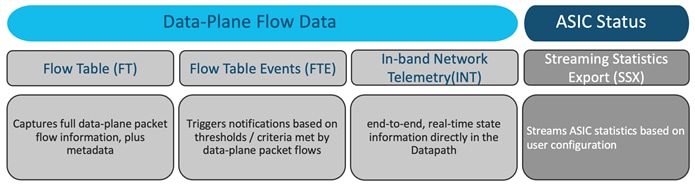
Figure 16 Cisco CloudScale H2R/H1 ASIC hardware telemetry
CloudScale H2R/H1 ASIC Flow Table (FT), Flow Table Event (FTE) and NetFlow
The flow table, in conjunction with H2R and H1 ASICs, serves the purpose of gathering comprehensive information pertaining to 5-tuple flows and additional metadata related to packet forwarding. This includes:
● 5-tuple flow information
● Interface/queue details
● Flow start/stop timestamps
● Packet disposition indicators (for drop events)
● Burst measurements
A notable feature of the flow table in the context of H2R and H1 ASICs is that each egress slice possesses a dedicated flow table, and the size of each table has been expanded to accommodate 128,000 entries per slice. What sets the flow table apart is its capability to export flow data directly from the ASIC without relying on CPU intervention. The ASIC can encapsulate the flow records into packets and transmit them directly to the front panel port, all without involving the CPU or software. This approach ensures minimal impact on switch performance.
In addition, flow table event (FTE) triggers notifications based on criteria or thresholds met by data plane packet flows.
These recorded flow table entries find application in Nexus Dashboard Insight (NDI) and NetFlow analysis. In Figure 17, we observe the utilization of the flow table in conjunction with NDI, while Figure 18 illustrates the utilization of the flow table in the context of NetFlow.
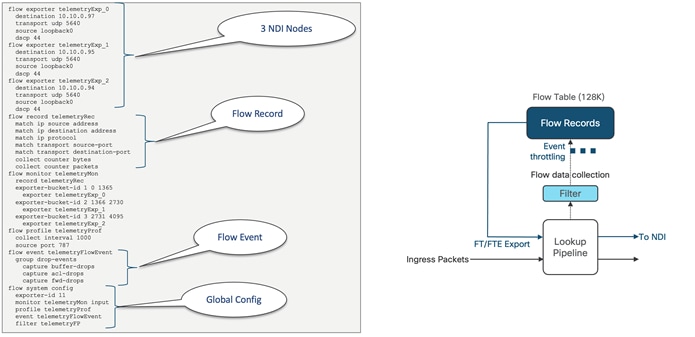
Figure 17 Flow Table usage with Nexus Dashboard Insights (NDI)
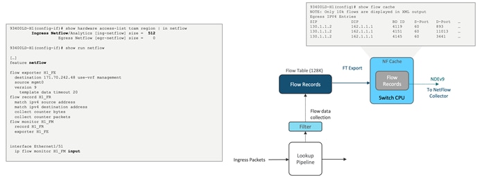
Figure 18 Flow Table usage with NetFlow
CloudScale H2R/H1 ASIC In-band Network Telemetry (INT)
INT is a framework that is designed to monitor, collect, and report flows and network states, by the data plane. INT sources embed the monitored INT flow information in normal data packets, and all the downstream devices add the same information with their details that are based on the source information received. INT is used to achieve per-packet network visibility with low overheads. The first record (INT instruction +metadata) will be inserted in data packet at the INT source node, whereas the second record (INT metadata) will be appended to same data packet at INT Transit node. The third Record (INT metadata) will be appended to INT stack at INT sink. INT sink will remove INT record and forward to INT Collector while original packet will be forwarded to server facing port. Figure 19 illustrates the INT architecture while Figure 20 extends on the INT modes.
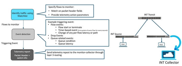
Figure 19 INT architecture
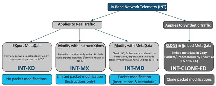
Figure 20 INT supported modes with H2R/H1 ASIC
Cisco H2R and H1 ASICs support INT version 1, version 2 and overload-INT for backward compatibility. ASIC supports all the three INT v2 modes:
● XD: Also called as postcard mode. Each node in the INT domain exports metadata based on the watchlist configuration.
● MX: Each node exports metadata based on the instructions embedded in the packet. Each intermediate node embeds instruction set in the packet.
● MD: Each transit node, starting from source, embed instructions and metadata in the packet, at the end the sink node, strips the complete metadata stack and exports it to the collector.
Figure 21 presents the INT export fields supported by the hardware in the Cisco CloudScale H2R/H1 ASICs.
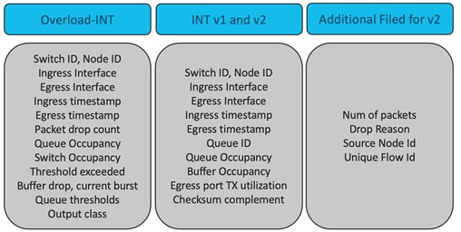
Figure 21 Cisco CloudScale H2R/H1 ASIC HW supported exported fields
CloudScale H2R/H1 Streaming Statistics Export (SSX)
SSX swiftly streams ASIC statistics based on user configurations. Here are some of the statistics supported by SSX:
● Interface counters (RMON counters)
● Ingress/egress queue depth and queue drops
● Egress total buffer depth
● Egress queue microbursts
The user has the ability to define streaming parameters, which includes deciding which statistics to use, determining their frequency, and selecting the collector to which they are sent. Another key feature is the direct export from the ASIC to the front-panel port. This process eliminates the need for switch CPU involvement, making it more efficient.
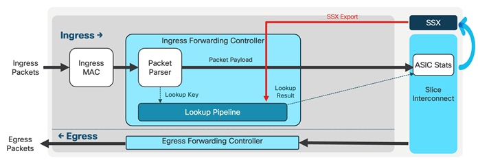
Figure 22 Streaming Statistics Export (SSX) with Cisco H2R/H1 ASIC
Cisco CloudScale H2R and H1 Span on Drop (SOD)
CloudScale H2R/H1 ASICs offer a crucial feature of mirroring dropped packets within the switch, which could be a result of configuration issues or a lack of buffer/queue space. Packet drops, though generally unwanted, are sometimes inevitable. The ability to mirror these dropped packets, also known as SPAN on Drop (SOD), allows network administrators to analyze the situation. This analysis can aid in fine-tuning system configurations or adjusting traffic flow to reduce packet drops. As displayed with Figure 23, the process of SPAN on Drop involves three steps: detecting the dropped packet, generating a copy of it, and then transmitting this dropped packet outside the switch.
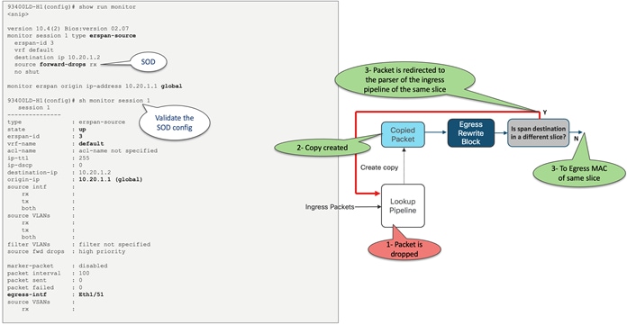
Figure 23 The process of SPAN on Drop with Cisco CloudScale H2R/H1 ASIC
A packet might be dropped for numerous reasons at different stages. From a mirroring standpoint, H2R/H1 ASIC support the following types of drops: those occurring in the ingress lookup pipeline or as a result of ingress forwarding, those happening in the egress buffer manager due to buffer occupancy, and those in the egress rewrite engine. Figure 24 illustrates the potential packet drop points in the H2R/H1 forwarding path.
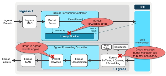
Figure 24 The potential packet drop points in the H2R/H1 forwarding path
CloudScale H2R/H1 ASIC Ingress Forwarding Drop
A packet may get dropped in the ingress pipeline due to various reasons including:
● VLAN mismatch
● MTU exception
● Time To Live (TTL) expiration
● Missing Forwarding Information Base (Fib Miss)
If a packet gets discarded, the egress buffer manager will not accept it for any forwarding action. SPAN supports all the ingress forwarding drops except ACL drops.
CloudScale H2R/H1 ASICs use following steps to mirror a dropped packet:
1. The SOD cap bit is set in internal header if a dropped packet is to be mirrored. NX-OS implementation is to have a catch all entry and mark all packets with the SOD cap bit.
2. Egress buffer manager will accept a dropped packet if the SOD cap bit is set. It will set mirror action in the opcode and assigns a SPAN index to be this packet.
3. The packet is set to be placed in the replication block, where it locates the SPAN destination port using SPAN table lookups guided by the SPAN index. After this, the replication block duplicates the packet. The replicated packet is then lined up to be transmitted out of the destination.
4. Packet be passed to packet rewrite block, which will add the ERSPAM-GRE header to the packet and send the packet to the egress MAC. The egress MAC will put the packet on the wire.
Figure 25 illustrates the CloudScale H2R/H1 SOD process.
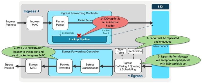
Figure 25 Cisco CloudScale H2R/H1 SOD process
CloudScale H2R/H1 ASIC Egress Buffer Drop
A buffer drop may occur if the egress buffer manager discards the packet due to memory limitations, such as an oversubscription drop and tail drop. This is often the case when the ingress rate exceeds the egress rate, leading to buffer congestion and the subsequent dropping of the unicast packet.
If the SOD cap bit is set, the egress buffer manager will convert the opcode to SPAN for these packets and assign a SPAN index. The rest of the procedures will continue as per the ingress forwarding drop.
CloudScale H2R/H1 ASIC Egress Rewrite Engine Drop
With the H2R/H1 ASIC, any unicast packet that is dropped during the rewrite process can be mirrored. The egress packet rewrite block conducts an egress TCAM lookup and during the ACL lookup, a packet can be tagged with an egress SOD cap. If a packet is dropped in the egress rewrite block, it will assign a SPAN index to the packet and notify the buffer manager. The buffer manager then transfers it to the replication block. Following this, the process continues as it does with an ingress forwarding drop.
CloudScale H2R/H1 ASIC Packet Recirculation
If the SPAN destination is in the same slice where SOD processing is taking place, it is forwarded from the egress pipeline. However, if it is in a different slice, the packet, after ERSPAN encapsulation in the egress rewrite block, is redirected to the parser of the ingress pipeline of the same slice using the recirculation port. Afterward, processing occurs as if the packet was received from a normal interface. Therefore, forwarding is based on the GRE-ERSPAN header. These packets are constrained by the recirculation bandwidth. The H2R/H1 ASIC provides two recirculation interfaces for each slice of 200 Gig. SPAN-on-drop uses one recirculation port, so the rate of SPAN traffic is capped at 200 Gig. Figure 26 illustrates the CloudScale H2R/H1 ASIC packet recirculation.
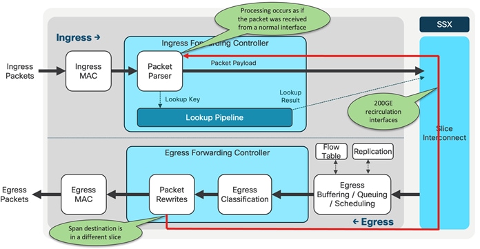
Figure 26 Cisco CloudScale H2R/H1 ASIC packet recirculation
Cisco CloudScale H2R and H1 ASIC Packet Buffer
CloudScale H2R/H1 ASIC On-Die Packet Buffer
The shared-memory egress buffered architecture is implemented in the Cisco CloudScale H2R/H1 ASICs. The H2R ASIC is equipped with an 80MB total, where each slide shares 40MB of the buffer. On the other hand, the H1 ASIC features a completely shared on-die packet buffer of 40MB. The structure of the on-die packet buffer for both H2R and H1 ASICs is displayed in Figure 27. The 40MB is distributed into 32 banks, each comprising 2K cells, with every cell containing 624 bytes.
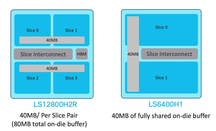
Figure 27 The on-die packet buffer architecture for H2R and H1 ASICs
The CloudScale H2R/H1 ASICs offer two cell allocation modes. In the default allocation, most of the buffer cells are dedicated to the user-defined space. When set to the 'no drop' mode, a separate space is created for the 'no drop' traffic classes. The cell allocations for the H2R in both 'drop' and 'no-drop' modes are illustrated in Figure 28 and Figure 29 respectively. Figure 30 and Figure 31 show these allocations for the H1 ASIC across two slices.
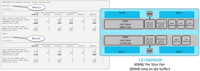
Figure 28 The default mode one-die packet buffer allocation for H2R
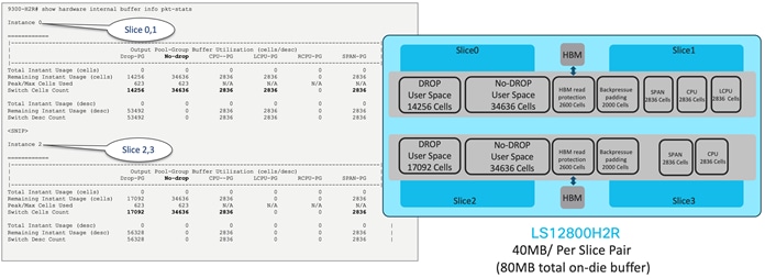
Figure 29 The no-drop mode one-die packet buffer allocation for H2R

Figure 30 The default mode one-die packet buffer allocation for H1
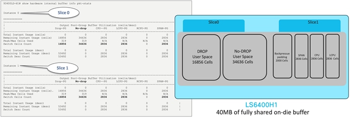
Figure 31 The no-drop mode one-die packet buffer allocation for H1
CloudScale H2R/H1 ASIC Intelligent Buffering
The on-die packet buffer, also referred to as smart buffers, of the CloudScale H2R/H1 ASICs are composed of three primary components:
1. Dynamic Buffer Protection (DBP)
2. Approximate Fair Drop (AFD)
3. Dynamic Packet Prioritization (DPP)
Dynamic Buffer Protection (DBP)
DBP is activated by default and manages buffer allocation for congested queues within the shared-memory architecture. It is the method through which the ASIC regulates buffer admission, ensuring equitable access to the available shared memory buffer across all ports and queues. There is a dynamically adjusted maximum threshold - if this threshold is exceeded, buffer admission is denied. If it is below the threshold, buffer admission is granted. This threshold is computed by multiplying the free memory by a configurable, per-queue Alpha (α) value (or weight). Alpha determines how assertively DBP preserves free buffer pages during congestion events. Figure 32 displays the buffer allocation for a specific port with varying alpha values, while Figure 33 provides an illustrative configuration example.
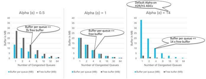
Figure 32 Cisco CloudScale H2R/H1 different alpha values
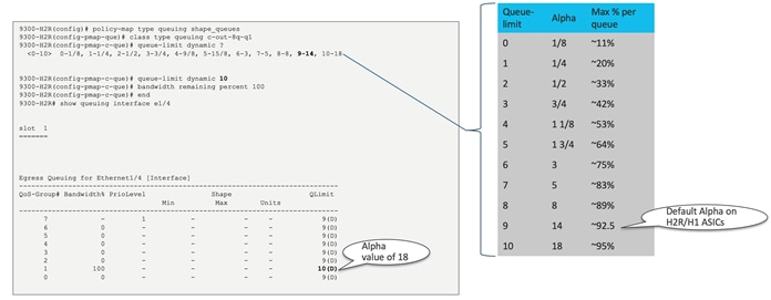
Figure 33 Cisco CloudScale H2R/H1 Queue limit (Alpha) configuration
Approximate Fair Drop (AFD)
AFD is an active queue-management scheme whose fundamental goal is to provide fair bandwidth allocation among flows that share a common egress queue. The fairness has two aspects. First, AFD distinguishes long-lived elephant flows from short-lived mice flows and exempts mice flows from the dropping algorithm so that mice flows will get their fair share of bandwidth without being starved by bandwidth-hungry elephant flows. Second, AFD tracks elephant flows and subjects them to the AFD algorithm in the egress queue to grant them their fair share of bandwidth. Figure 34 provides an illustrative configuration example.
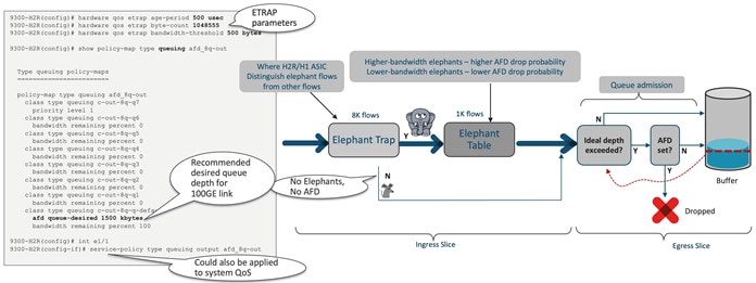
Figure 34 Cisco CloudScale H2R/H1 Approximate Fair Drop (AFD)
Dynamic Packet Prioritization (DPP)
Dynamic packet prioritization, or DPP, provides the capability to manage mice flows and elephant flows in the same traffic class separately for queuing. It effectively isolates them in two separate queues despite the fact that they belong to the same traffic class. This separation is not possible with the traditional simple queue management technologies because they lack flow awareness within a class. Figure 35 provides an illustrative configuration example.
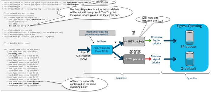
Figure 35 Cisco CloudScale H2R/H1 dynamic packet prioritization (DPP)
CloudScale H2R HBM Packet Buffer
Along with Smart buffers, the Cisco LS 12800 H2R ASIC also features an 8GB deep buffer. The deep buffer, also known as high bandwidth memory (HBM), is crucial for handling large traffic surges in the switch by providing an extra 8GB buffer on top of the existing buffers in the switch. The deep buffer system is distributed across four slices of the LS12800 H2R, with each slice receiving up to 2GB of buffer space. If this limit is exceeded, noticeable drops will occur.
The system includes the deep buffer feature by default, enabling any queue to tap into the buffers during periods of congestion. Notably, the deep buffer is situated outside the traditional switch pipeline, thereby offering independent accounting and buffering functions. Packets in the deep buffer are stored as novels, with one novel equating to 256KB. The LS12800 H2R handles the conversion each time a packet is added or removed from the high bandwidth memory. To constrain the queues, deep buffer implements static thresholding, with any packets that surpass this threshold being tail dropped.
The on-chip packet buffer is solely designed to support dynamic alpha configuration, while the high bandwidth memory is limited to static thresholding. As a result, the alpha programming is performed only in the on-chip system, while the off-chip system continues to validate the queue based on maximum cell/novels thresholds. This architecture ensures that each queue functions optimally based on its particular supporting configuration.
It is important to mention that the Quality of Service (QoS) command line interface (CLI) does not provide any specific sub-options for deep buffer. Rather, all existing QoS configurations are reused, and the internal code base guides the deep buffer programming using a predefined logic. The architecture of the H2R ASIC HBM is depicted in Figure 36. Each slice is assigned with 6,881,280 Cells, or 16384 novels. Here, one cell equals 624 Bytes while one novel amounts to 256K Bytes.
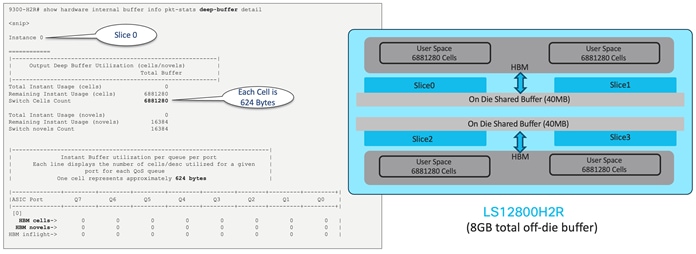
Figure 36 Cisco CloudScale H2R ASIC deep buffer architecture
Cisco CloudScale H2R and H1 ASIC AI/ML
Artificial Intelligence and Machine Learning (AI/ML) applications are being used increasingly in today’s data centers, and the Cisco CloudScale H2R and H1 ASIC have the hardware and software capabilities to provide the right latency, congestion-management mechanisms, and telemetry to meet the requirements of those applications.
Remote direct memory access (RDMA) is a well-known technology used for high performance computing (HPC) and storage networking environments. The advantages of RDMA are the high throughput and low latency transfer of information between compute nodes at the memory-to-memory level, without burdening the CPU. This transfer function is offloaded to the network adapter hardware to bypass the operating system software network stack. This technology also has the advantage of reduced power requirements. Figure 37 illustrates the direct GPU memory communication using RDMA.
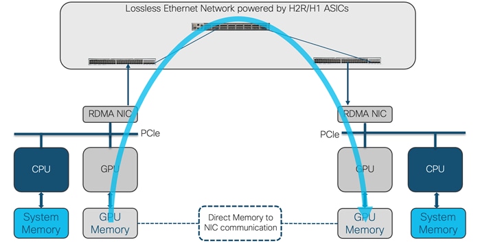
Figure 37 Direct GPU memory communication using RDMA
In AI/ML clusters, RDMA is used to communicate memory-to-memory between GPUs over the network. This implementation is called GPUDirect RDMA. RoCEv2 is an excellent transport for GPUDirect RDMA.
For RoCEv2 transport, the network must provide high throughput and low latency while avoiding traffic drops in situations where congestion occurs. The Cisco CloudScale H2R and H1 are built for data center networks and provide the required low latency. With up to 12.8 Tbps of bandwidth per ASIC, these switches provide the very high throughput required to satisfy AI/ML clusters running on top of RoCEv2 transport. The CloudScale H2R and H1 also provide support and visibility in a lossless network through software and hardware telemetry in both ECN and PFC.
Explicit Congestion Notification (ECN)
In situations where congestion information needs to be propagated end-to-end, ECN can be used for congestion management. ECN is marked in the network node where congestion is experienced inside the IP header type of service (TOS) field in the 2 least significant bits. When a receiver gets a packet with the ECN congestion experience bits set to 0b11, it generates and sends a congestion notification packet (CNP) back to the sender. When the sender receives the congestion notification, it slows down the flow that matches the notification. This end-to-end process is built in the data path, and as such is an efficient way to manage congestion.
Priority flow control was introduced in Layer 2 networks as the primary mechanism to enable lossless Ethernet. Flow control was driven by the class of service (COS) value in the Layer 2 frame, and congestion is signaled and managed using pause frames and a pause mechanism. However, building scalable Layer 2 networks can be a challenging task for network administrators. Because of this, network designs have mostly evolved into Layer 3 routed fabrics.
As RoCEv2 can be routed, PFC was adjusted to work with differentiated services code point (DSCP) priorities to signal congestion between routed hops in the network. DSCP is a mechanism used for classifying network traffic on IP networks. It uses the 6-bit differentiated services field in the IP header for packet classification purposes. Using Layer 3 marking enables traffic to maintain classification semantics across routers. Since PFC frames use link local addressing, the network devices can receive and perform pause signaling for both routed and switched traffic. PFC is transmitted per-hop, from the place of congestion to the source of the traffic. This step-by-step behavior could take time to be propagated to the source. PFC is used as the primary tool to manage congestion for RoCEv2 transport.
Cisco CloudScale H2R and H1 ASICs support both PFC congestion management and ECN marking with either weighted random early detection (WRED) or approximate fair drop (AFD) to indicate congestion in the network node. Figure 38 illustrates the RoCEv2 configuration example with the Cisco Nexus 9300-H1.
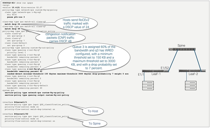
Figure 38 RoCEv2 configuration example with Cisco Nexus 9300-H1
The Cisco Nexus 9332D-H2R switch introduces the first switch with deep buffer capability to the Nexus 9000 fixed-switch portfolio. The switch is built with backward-compatible 400G optical interface Quad Small Form-Factor Pluggable–Double Density (QSFP-DD) ports to migrate existing data center fabrics from 40-Gbps and 100-Gbps speeds to 400 Gbps; it also offers various lower port speeds and densities, including 10, 25, 40, 50, 100, and 200 Gbps, using breakouts. The Cisco Nexus 9332D-H2R Switch is based on Cisco® CloudScale technology equipped to support next-generation cloud architecture.
The Cisco Nexus 9332D-H2R is a 1-Rack-Unit (1RU) 32-port 400 Gigabit Ethernet switch that supports 12.8 Tbps of bandwidth. The switch provides 80MB of on-die packet buffer and 8GB of high bandwidth memory (or HBM) with MACsec capability on all 32 ports.
The Cisco Nexus 9332D-H2R is equipped with support for the precision time protocol (PTP) providing class C timing accuracy suitable for telecom and media profiles. Leveraging PTP and Synchronous Ethernet, it ensures highly accurate frequency and time distribution. The front and rear views of the 9332D-H2R are depicted in Figure 39 and Figure 40, respectively, while Figure 41 provides a visual representation of the switch on chip (SOC) architecture.
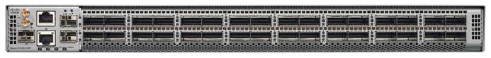
Figure 39 Cisco Nexus 9332D-H2R switch, frontside

Figure 40 Cisco Nexus 9332D-H2R switch, rear side
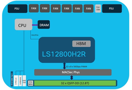
Figure 41 Cisco Nexus 9332D-H2R Switch on Chip (SOC) architecture
Leveraging the multi-slice architecture of the LS12800H2R ASIC, it is critical to comprehend how the front panel ports correspond to the CloudScale ASIC slices. The mapping of the front panel ports of the Cisco Nexus 9332D-H2R is depicted in Figure 42.
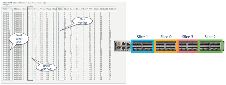
Figure 42 Cisco Nexus 9332D-H2R switch port mapping
The Cisco Nexus 93400LD-H1 switch introduces precision time protocol (PTP) with class C timing accuracy to the Nexus 9000 fixed switch portfolio. Through PTP and Synchronous Ethernet, it delivers frequency and time distribution with high accuracy. The switch is built with backward-compatible 400G optical interface Quad Small Form-Factor Pluggable–Double Density (QSFP-DD) ports for high density aggregation at 400 Gbps speed; it also offers various lower port speeds and densities, including 10, 25, and 50 Gbps. The Cisco Nexus 93400LD-H1 switch is based on Cisco® CloudScale technology equipped to support next-generation cloud architecture.
The Cisco Nexus 93400LD-H1 is a 1-Rack-Unit (1RU) switch featuring 48 ports of 50 Gigabit Ethernet and 4 ports of 400 Gigabit Ethernet, supporting a bandwidth of 4 Tbps. The switch includes a fully shared on-die packet buffer of 40MB, with MACsec capability available on all ports. Figure 43 and Figure 44 display the front and rear views of the 93400LD-H1, and Figure 45 shows the switch on chip (SOC) architecture.
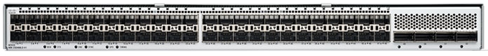
Figure 43 Cisco Nexus C93400LD-H1 switch, frontside
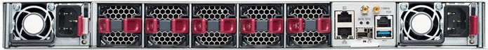
Figure 44 Cisco Nexus C93400LD-H1 switch, rear side
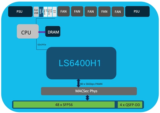
Figure 45 Cisco Nexus C93400LD-H1 Switch on Chip (SOC) architecture
Figure 46 provides a visual representation of the front panel port arrangement of the Cisco Nexus C93400LD-H1.
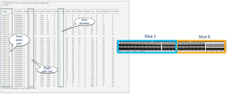
Figure 46 Cisco Nexus C93400LD-H1 switch port mapping
Nexus 9300-H MACsec Hardware Encryption
MACsec offers encryption at the line rate on a link-level, hop-by-hop basis. Both the Nexus 9332D-H2R and 93400LD-H1 models support MACsec across all ports. They also support IEEE 802.1AE 128-bit and 256-bit AES encryption with MKA Key Exchange. An example of a MACsec configuration with the Nexus 9300-H is demonstrated in Figure 47.
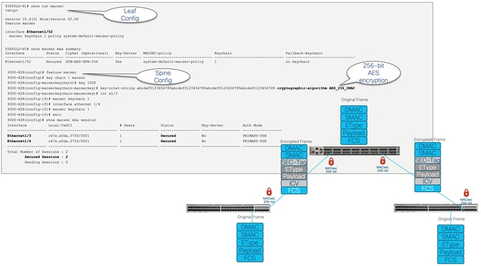
Figure 47 Example of MACsec encryption on Cisco Nexus C9300-H
The advent of 5G networks creates unprecedented opportunities and challenges for telcos and enterprises to deliver secure services and new user experiences. Each new generation of mobile networks has driven the need for increased precision and accuracy in synchronization standards and solutions. 5G technology is needed to support Ultra-Reliable Low-Latency Communications (URLLC) services, and new revenue generating services such as autonomous vehicle connectivity and eHealth services are simply not possible without highly accurate and reliable time synchronization. Even services such as massive Industrial Internet of Things (IIoT) and other industrial automation services require reliable time synchronization. Figure 48 showcases the time synchronization within a data center fabric.
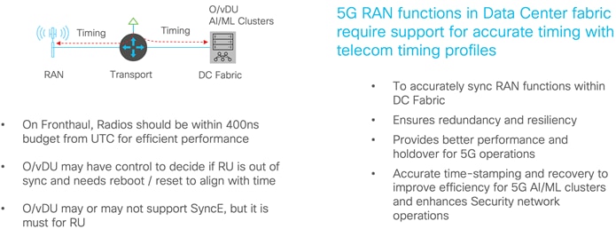
Figure 48 The time synchronization within a data center fabric
The Open Radio Access Network Architecture (O-RAN) or virtual RAN (vRAN) present a novel approach for service providers to meet the requirements of 5G networks. The Cisco Nexus 9300-H holds a significant role in the O-RAN/vRAN transition, as the currently deployed solution for far edge data centers (DC) necessitates the following features:
● Telecom profile G.8275.1(full timing)
● Telecom profile G.8275.2 (partial timing support) whenever G.8275.1 is not possible
● Synchronous Ethernet (SyncE)
● Line rate 10G/25G/50G, 100G/400GE interfaces
The PTP telecom profile G.8275.1 necessitates both PTP and SyncE across the entire path from T-GM to T-TSC. Furthermore, each network node requires boundary clock support, with PTP frames distributed using Layer 2 multicast. This makes the Nexus 9300-H an ideal candidate due to its class C accuracy. Figure 49 depicts the deployment of O/vRAN aided by a far edge DC, while Figure 50 showcases the deployment of the far edge DC using the Cisco Nexus 9300-H that operates the PTP 8275-1 telecom profile.
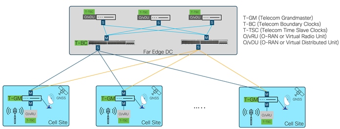
Figure 49 O/vRAN architecture with a far edge DC deployment
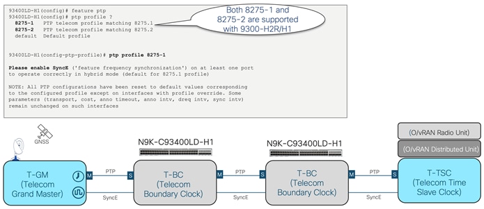
Figure 50 Cisco Nexus 9300-H deployments in a far edge DC with the 8275-1 PTP telecom profile
In addition to the 8275-1 telecom profile, Cisco Nexus 9300-H also supports the G.8275.2 telecom profile, which is based on the partial timing support from the network, hence nodes are not required to be directly connected. This profile is aimed at operation over existing networks, where boundary clocks are placed at strategic locations to reduce noise. It uses PTP over IPv4 and IPv6 in unicast mode instead of Layer 2 multicast frames used in G.8275-1. Figure 51 showcases the deployment of the far edge DC using the Cisco Nexus 9300-H that operates the PTP 8275-2 telecom profile.
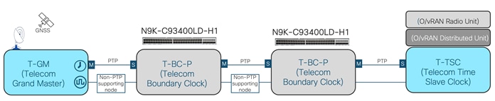
Figure 51 Cisco Nexus 9300-H deployments in far edge DC with 8275-2 PTP telecom profile
The Cisco Nexus 9300-H platform switches, incorporating Cisco's cutting-edge CloudScale H2R and H1 ASICs, establish a benchmark for contemporary data center switching solutions. These switches offer a variety of features including adaptable forwarding tiles, enhanced ACL TCAM regions, smart buffer management, deep buffer, advanced hardware telemetry and visibility, MACsec, and PTP with class C timing accuracy. These features equip customers with the necessary tools to optimize performance and efficiency in their data center operations.
● Cisco Nexus 9500 CloudScale Line Cards and Fabric Modules White Paper
● Flexible Forwarding Table on Nexus 9000
● Cisco Data Center Networking Blueprint for AI/ML Applications
● Cisco Validated Design for Data Center Networking Blueprint for AI/ML Applications
● Classification TCAM with Cisco CloudScale ASICs for Nexus 9000 Series Switches White Paper