Zero-Touch Provisioning of VXLAN Fabrics using Inband POAP with NDFC
Available Languages
Bias-Free Language
The documentation set for this product strives to use bias-free language. For the purposes of this documentation set, bias-free is defined as language that does not imply discrimination based on age, disability, gender, racial identity, ethnic identity, sexual orientation, socioeconomic status, and intersectionality. Exceptions may be present in the documentation due to language that is hardcoded in the user interfaces of the product software, language used based on RFP documentation, or language that is used by a referenced third-party product. Learn more about how Cisco is using Inclusive Language.
- US/Canada 800-553-2447
- Worldwide Support Phone Numbers
- All Tools
 Feedback
 Feedback
The current design trend is to deploy multiple smaller data centers closer to the data as opposed to the centralized data center approach in past. With more smaller data centers coming up there is a need of complete automation in the provisioning process. By using the POAP (Power On Auto Provisioning) feature of Cisco Nexus switches, NDFC (Nexus Dashboard Fabric Controller) can fully automate the deployment of new datacenters, reducing overall time and effort and eliminating any human errors.
Note: The documentation set for this product strives to use bias-free language. For the purposes of this documentation set, bias-free is defined as language that does not imply discrimination based on age, disability, gender, racial identity, ethnic identity, sexual orientation, socioeconomic status, and intersectionality. Exceptions may be present in the documentation due to language that is hardcoded in the user interfaces of the product software, language used based on RFP documentation or language that is used by a referenced third-party product. Learn more about how Cisco is using Inclusive Language.
Power On Auto Provisioning (POAP) automates the process of upgrading software images and installing configuration files on devices that are being deployed in the network for the first time. When a device with the POAP feature boots and does not find the startup configuration, the device enters POAP mode, locates a DHCP server, and bootstraps itself with its interface IP address, gateway, and DNS server IP addresses. The device also obtains the IP address of a TFTP server and downloads a configuration script that enables the switch to download and install the appropriate software image and configuration file.
POAP allows you to provision devices without performing any manual configuration, therefore, referred to as Zero-touch provisioning of devices.
Depending upon the interface used on the device for bootstrap, POAP can be categorized follows:
● Inband POAP uses one of the device’s front-panel ports.
● Out-of-band (OOB) POAP uses the mgmt0 port on the device.
Some important prerequisites for POAP are:
● Devices must support POAP.
● Device should either have no startup configuration or the boot poap enable command must be configured for the device to bypass startup configuration and enter POAP mode.
● DHCP server with scope defined
● Script Server to store POAP script and devices’ configuration files
● (Optional) Software and Image Repository server to store software images for the devices
For more details on POAP, see Using PowerOn Auto Provisioning in Cisco Nexus 9000 NX-OS Fundamentals Configuration Guide.
Cisco DCNM supports POAP for both VXLAN and LAN Classic fabrics. However, it is limited to OOB POAP (POAP over device’s management port). Beginning with Cisco NDFC Release 12.1.1e, Inband POAP is supported for VXLAN and External fabrics.
Apart from support for POAP, you can also configure NDFC as DHCP server, and, Script and Software/Image repository, therefore simplifying and centralizing the overall POAP operation.
NDFC supports creating VXLAN fabrics by using either P2P IP addressing or IP Unnumbered addressing in the underlay. Inband POAP is supported for both VXLAN and External fabrics and can be referred to as follows:
● Inband POAP for Numbered Fabric
● Inband POAP for IP-Unnumbered Fabric
Adding POAP-enabled switches is supported for both Greenfield and Brownfield deployments. Also, POAP can be used with pre-provisioned devices.
This document describes Inband POAP for VXLAN fabrics on both Numbered and IP-Unnumbered fabrics.
The following sections provide detailed information about the requirements for Inband POAP.
There are two NDFC placement options for POAP:
● NDFC as Layer-2 adjacent
● NDFC over Layer-3
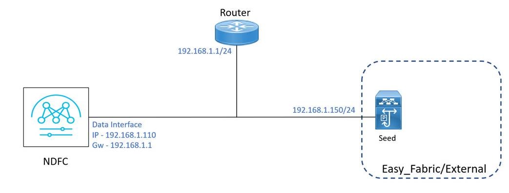
NDFC is Layer 2 adjacent with the seed switch. Nexus Dashboard data interface and seed interface are in same broadcast domain and configured with IP of the same subnet.
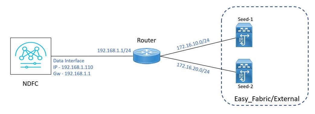
NDFC is connected to the fabric over routed infrastructure. This offers design flexibility for NDFC. This requires some routing configuration along with DCHP relay that is configured on router’s interface connected to the seed switch.
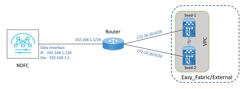
Seed switches can also be in VPC as shown in the following topology.
LAN Device Management Connectivity
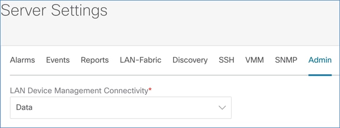
For Inband POAP, the fabric must be reachable through the Nexus Dashboard data interface. By default, NDFC uses management interface for device connectivity.
To enable connectivity over data interface, from NDFC Web UI, choose LAN > Settings > Server Settings. Choose Data from the Admin tab from the LAN Device Management Connectivity field.
By default, NDFC manages the devices over OOB network. Nexus switches have a dedicated management port (mgmt0) used to provide OOB connectivity to the device for management purposes.
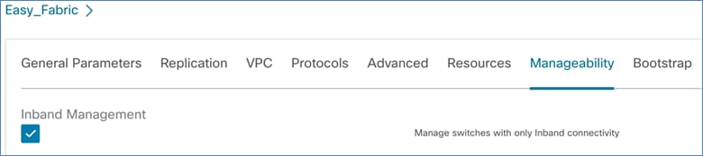
For Inband POAP the devices must be managed by the inband address. To enable Inband management for the devices, edit the Fabric and check the Inband Management check box on the Manageability tab.
For POAP, DHCP server manages the temporary IP addresses to the devices during bootstrap process. Also, details of Script and Software/Image repository servers are also provided along with DHCP.
For OOB POAP, DHCP scope must be defined for management subnet. The IP addresses to all the devices are assigned from this scope over DHCP.
For Inband POAP, DHCP scopes are defined only for seed subnets, which is used to allocate IPs for the seed devices on their seed (bootstrap) interfaces over DHCP. The non-seed devices of the fabric get the IP addresses assigned from the underlay routing subnet range for fabric. For the IP-unnumbered fabric, additional DCHP scope Switch Loopback DHCP Scope is required.
NDFC supports both internal and external DHCP servers for POAP operation. When NDFC is configured as DHCP server it is referred as Internal (local) DHCP, otherwise can point to an External DCHP server.
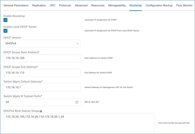
To enable local DHCP, in the Fabric Settings, check Enable Local DHCP Server and define DHCP scope parameters in Start Address, End Address and Default Gateway, Subnet Prefix fields.
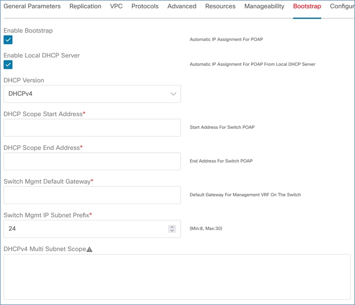
You can configure more DHCP scope using DHCPv4 Multi Subnet Scope freeform field. You must define one scope per line in format – Start_IP, End_IP, Gateway, Prefix.
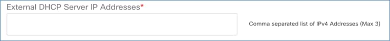
If External DCHP is used, server details can be provided in External DHCP Server IP Addresses field under Bootstrap tab.
Routing Configuration on Nexus Dashboard
By default, Nexus Dashboard uses its management interface as egress unless explicit routes are defined. As only Nexus Dashboard data interface is supported as device management connectivity, you must define the following routes on the Nexus Dashboard, pointing its data interface as egress.
Define the following routes per fabric on Nexus Dashboard to maintain reachability and bootstrap operation:
Underlay Routing Loopback subnet
With Inband POAP, devices are managed using their Underlay Routing loopback (default is loopback 0) and this loopback gets an IP address that is assigned from underlay routing (IGP/BGP) loopback subnet. Therefore, a static route for this subnet should be defined on ND pointing Data interface.
Underlay subnet
For numbered fabric, the links between spine and leafs are configured as P2P and assigned /30 or /31 addresses from Underlay Subnet IP Range. Define route for fabric’s underlay IP subnet range which is needed for DHCP relay to work.
Note: This is only applicable for numbered fabric.
Seed subnet
This step is only applicable when NDFC is connected to the fabric over a routed infrastructure and required for NDFC to be able to bootstrap the seed switches. The IPs from this subnet are allocated over DHCP on seed interfaces during bootstrap. External router’s interfaces connecting to seeds have IPs from same subnets configured manually.
Seed switch acts as the entry point to the fabric for NDFC and like any other device, seed switch is also part of the fabric.
Seed switch can be of any role Spine, Border, or Leaf and a fabric can have more than one seed switches.
A seed switch has two types of interfaces:
● Seed (bootstrap) interface
● Core-facing (fabric-facing) interface
The interface on seed switch facing NDFC is referred as seed (bootstrap) interface which is configured as Layer-33 interface and assigned an IP address over DHCP.
The core-facing interfaces on the seed switch connect itself to the rest of the fabric. These interfaces are configured as normal P2P underlay links of the fabric. NDFC automatically configures DHCP relay on the core-facing interfaces of seed and spine switches, so that DHCP requests from downstream fabric devices are relayed back to NDFC.
In case of multiple seed switches in a fabric, the fabric facing interfaces must be consistent across all the seed switches.
Inband POAP Operation on Fabric
Entire Inband POAP operation can be explained in the following 3 steps (or 2 steps if the spine is used as seed device).
Seed switches are the first devices to be bootstrapped and acts as an entry-point to the fabric for NDFC. Seed switches can be of roles Leaf, Spine, Border, or Border Gateway. NDFC allocates IPs to seed switches from the configured DHCP Pool.
This is applicable only if the seed switches are not in spine role.
For Numbered fabric, the DHCP offer made by NDFC to spine switches is from the same subnet which is configured on the interface of the upstream seed switch.
For IP-Unnumbered fabric, NDFC provides DHCP offer to spine switches from Switch Loopback DHCP Scope.
All the devices connected to spines are bootstrapped. DHCP offers are made similar to spine switches.
Inband POAP for Numbered Fabric
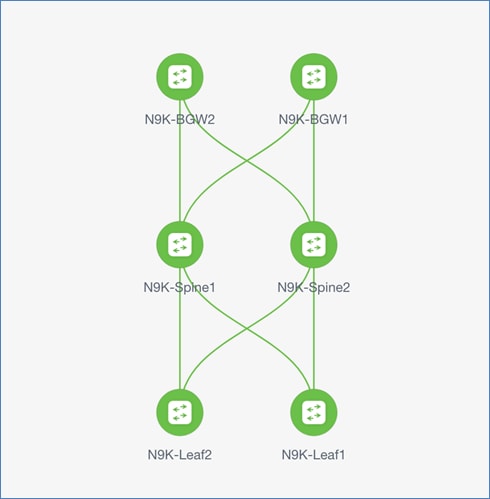
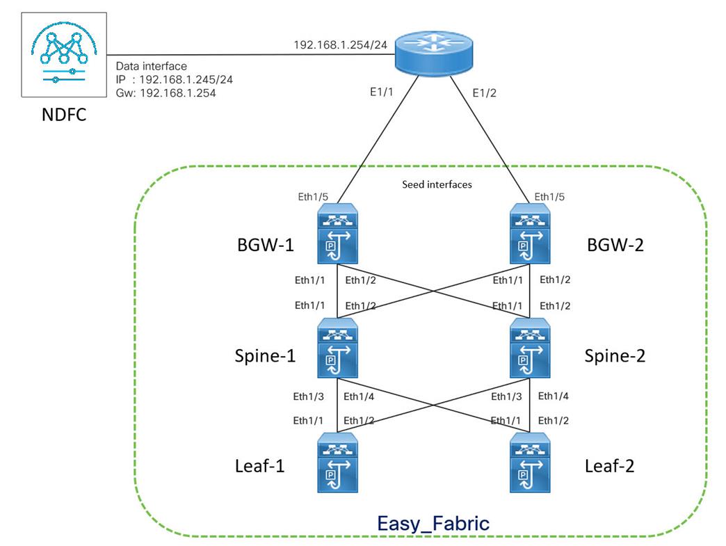
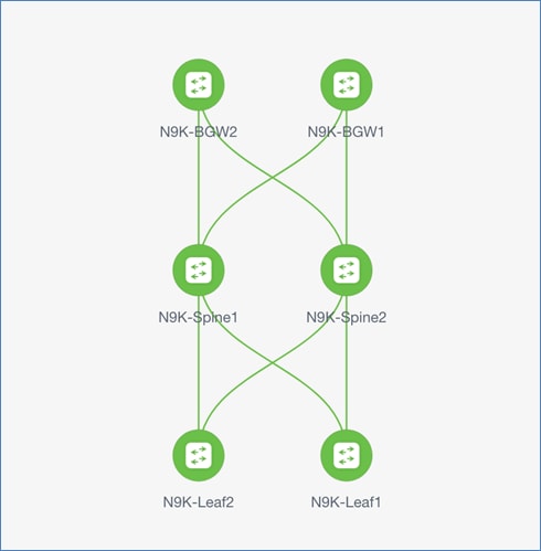
Let us configure the fabric using Inband POAP. A sample topology is shown in the following image.
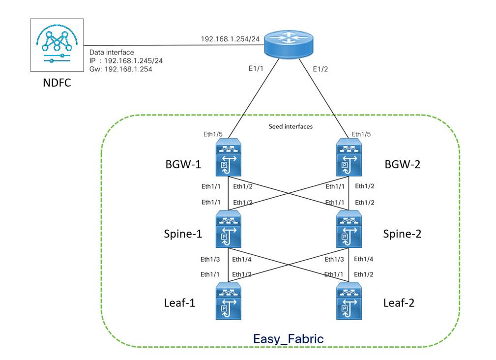
NDFC is Layer-3 adjacent to the fabric and connected via External router. The external router connects to the seed switches in the fabric and also configured as gateway for NDFC. The seed switches are in BGW (Border Gateway) role, Eth1/5 interfaces are seed interfaces and Eth1/1-2 are the core-facing interfaces on both the seeds. Spines switches are directly connected to the seeds and Eth1/1-4 are the core-facing interfaces on both of them. This fabric is using NDFC’s provided default subnet ranges 10.2.0.0/22 and 10.4.0.0.16 for IGP/BGP Loopback and Underlay Routing subnets respectively. 172.16.10.0/24 and 172.16.20.0/24 are the seed subnets used in this topology.
Enable local DHCP on NDFC and define DHCP scope for both the seed subnets – 172.16.10.10/24 and 172.16.20.0/24, as shown in the following image.
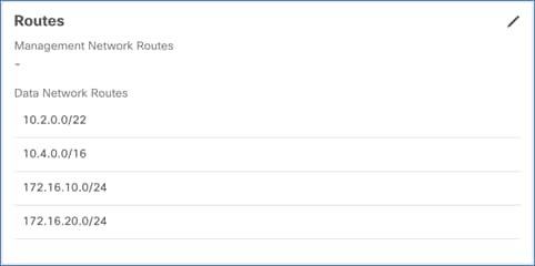
To define routes, on the Nexus Dashboard, choose Admin Console > Infrastructure > Cluster Configuration > Routes. Add Data Network Routes for 10.2.0.0/22 (IGP/BGP loopback subnet), 10.4.0.0/16 (Underlay Routing subnet range) and 172.116.10.0/24 & 172.16.20/0/24 (seed subnets).
Enter the core-facing (fabric facing) interface details for seed and spine switches. eth1/1 and eth1/2 are the core-facing interfaces on both the seeds and Eth1/1-4 are the core-facing interfaces of the spines –
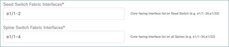
Note: If there is more than one seed or spine, the core-facing interfaces must be consistent among the seeds or spines, and correctly match the physical cabling. If the core-facing interface configuration is wrong, NDFC fails to bring up the fabric.
Configuration on External Router
The external router plays a vital role in Inband POAP. The external router is directly connected to the seed switches and forms BGP neighborship to learn routes from the fabric. Using these BGP learned routes, NDFC can reach the fabric devices.
All interfaces of edge router connected to seed devices are configured with IPs from seed subnets and should have DHCP Relay configured with Nexus Dashboard Data interface IP address.
interface Ethernet1/1
description ** connected to Seed switch BGW1 **
no switchport
ip address 172.16.10.1/24
ip dhcp relay address 192.168.1.245
no shutdown
interface Ethernet1/2
description ** connected to Seed switch BGW2 **
no switchport
ip address 172.16.20.1/24
ip dhcp relay address 192.168.1.245
no shutdown
You must configure Static routes for seed switches’ inband management IP addresses (assigned on loopback 0) on the external router. The next-hop for these routes is the IP address assigned on the seed interface of the respective seed switch. These routes are required for NDFC to reach seed switches. BGP configuration is applied from the neighborship with external router and advertises reachability for the rest of the fabric.
ip route 10.2.0.10/32 172.16.10.10
ip route 10.2.0.11/32 172.16.20.10
Note: The previous step is only applicable for seed switches, which must be configured with the same IP addresses on their loopback0 and seed interfaces.
BGP configuration on external router forms neighborship with the seed devices. The following is the sample BGP configuration.
feature bgp
router bgp 55
address-family ipv4 unicast
maximum-paths 4
neighbor 172.16.10.10
remote-as 200
update-source Ethernet1/1
address-family ipv4 unicast
next-hop-self
neighbor 172.16.20.10
remote-as 200
update-source Ethernet1/2
address-family ipv4 unicast
next-hop-self
After configuring the edge router and enabling NDFC fabric for Inband POAP, you can begin bootstrapping the device.
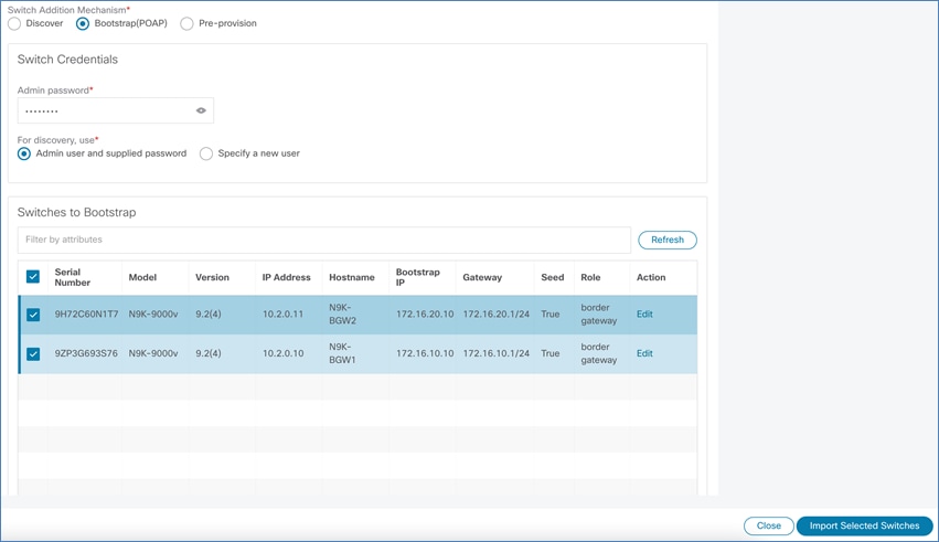
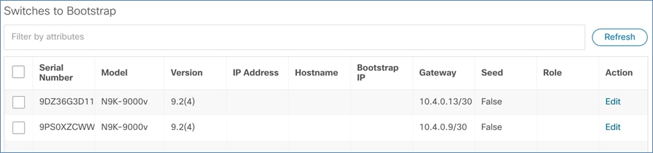
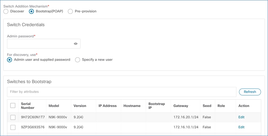
When NDFC fabric is enabled for POAP and devices are in POAP loop, on the NDFC Web UI, choose Fabric Overview > Switches > Add Switches. The seed switches appear on the Bootstrap tab.
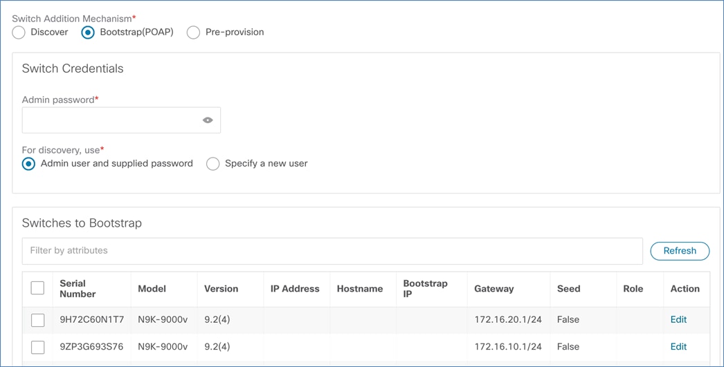
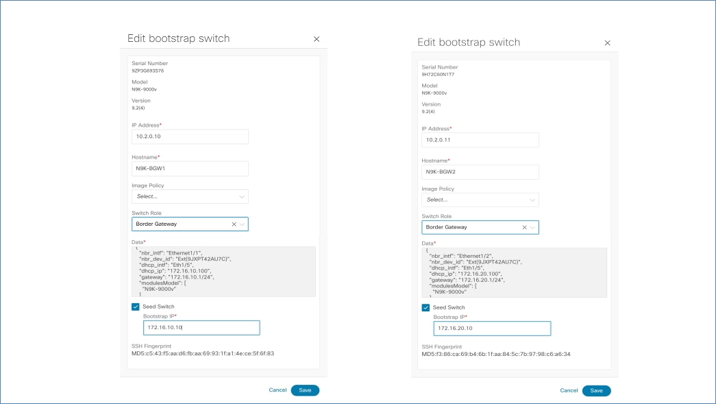
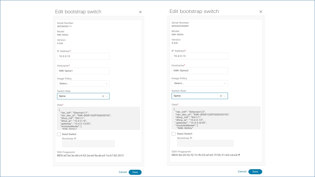
For each of the seed switches click Edit and update following parameters:
a) IP Address (must be same as per the static route configured on external router)
b) Hostname
c) Image policy (optional)
d) Switch Role
e) Check Seed Switch check box and enter the permanent Bootstrap IP address for seed interfaces.
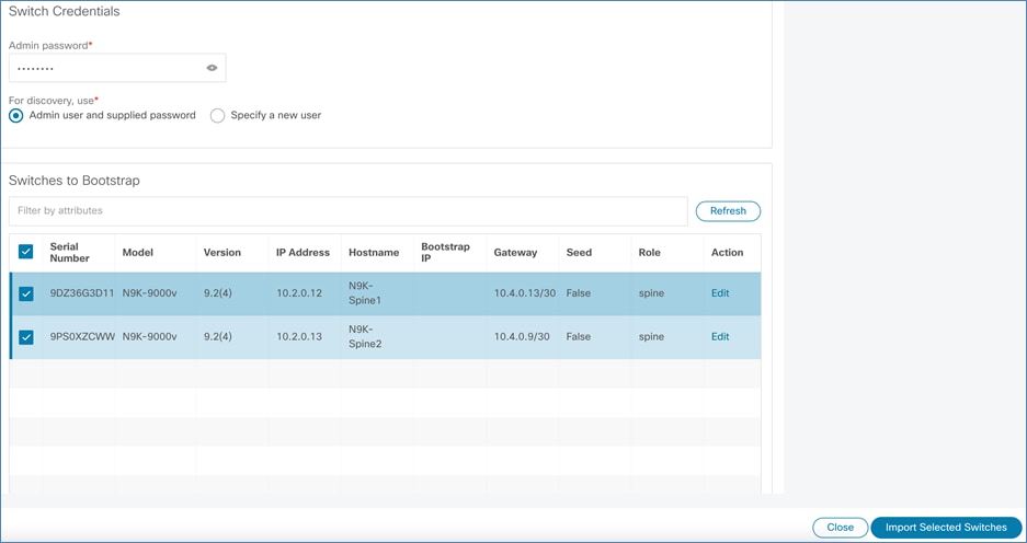
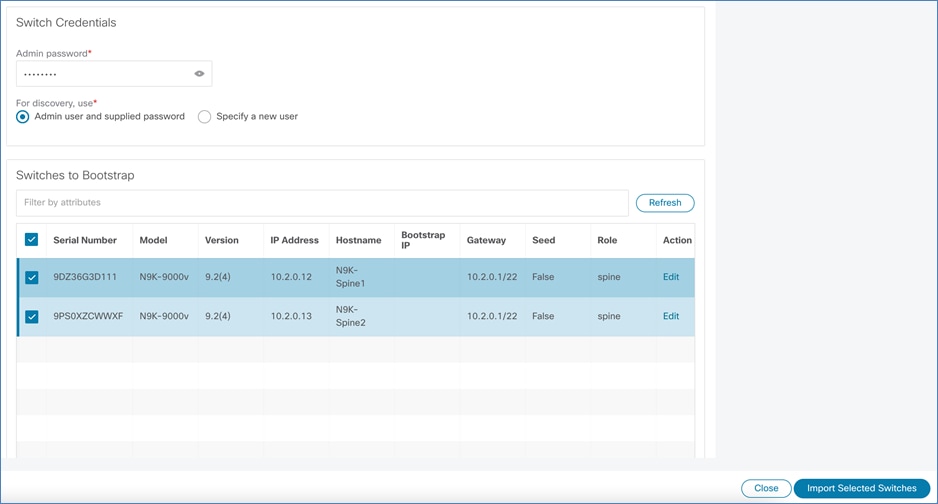
Enter the password in Admin password field and select both the seed switches. Click Import Selected Switches.
The seed switches reload after bootstrap. After the reload, seed switches are configured with VXLAN-related configuration.
a) Routing and VTEP loopbacks
b) Seed interface
c) Core facing interfaces
d) DHCP Relay on core facing interfaces
e) Static route configured for Nexus Dashboard IPs
f) OSPF enabled on core facing interfaces and redistribution of static routes
g) BGP process instantiated
Core Facing interfaces
Each of the core-facing interfaces gets /30 or /31 IP addresses assigned from Underlay Subnet IP Range (10.4.0.0/16).
Table 1. Core-facing interface config on seeds
| Seed-1 |
Seed-2 |
| interface Ethernet1/1 no switchport mtu 9216 ip address 10.4.0.13/30 tag 54321 ip ospf network point-to-point ip router ospf UNDERLAY area 0.0.0.0 ip pim sparse-mode ip dhcp relay address 192.168.1.245 no shutdown
interface Ethernet1/2 no switchport mtu 9216 ip address 10.4.0.9/30 tag 54321 ip ospf network point-to-point ip router ospf UNDERLAY area 0.0.0.0 ip pim sparse-mode ip dhcp relay address 192.168.1.245 no shutdown |
interface Ethernet1/1 no switchport mtu 9216 ip address 10.4.0.5/30 tag 54321 ip ospf network point-to-point ip router ospf UNDERLAY area 0.0.0.0 ip pim sparse-mode ip dhcp relay address 192.168.1.245 no shutdown
interface Ethernet1/2 no switchport mtu 9216 ip address 10.4.0.1/30 tag 54321 ip ospf network point-to-point ip router ospf UNDERLAY area 0.0.0.0 ip pim sparse-mode ip dhcp relay address 192.168.1.245 no shutdown |
Static Routes for Nexus Dashboard IPs
The following static routes are configured for the seed device to reach back to Nexus Dashboard.
ip route 192.168.1.245/32 172.16.10.1 tag 12345 <---- Route for DHCP Server
ip route 192.168.1.246/32 172.16.10.1 tag 12345 <---- Route for POAP Script server
ip route 192.168.1.247/32 172.16.10.1 tag 12345 <---- Route for Syslog server
BGP Configuration
Redistribution of OSPF and Connected routes are configured under IPv4 address-family.
router bgp 200
router-id 10.2.0.10
address-family ipv4 unicast
redistribute direct route-map fabric-rmap-redist-direct
redistribute ospf UNDERLAY route-map fabric-rmap-bgp-redist-ospf
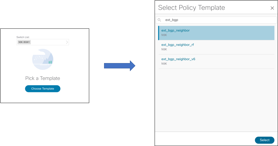
When the seed switches are online after reload, apply External BGP Neighbor policy to both seeds switches to form neighborship with the external router. This is mandatory for NDFC to establish reachability with other fabric devices.
On NDFC Web UI, choose Policy > Actions > Add Policy from the Switch List drop-down list, select the seed switches to apply policy. Click Choose Template and select ext_bgp_neighbor template.
Enter all the required parameters to form BGP neighborship with the external router.
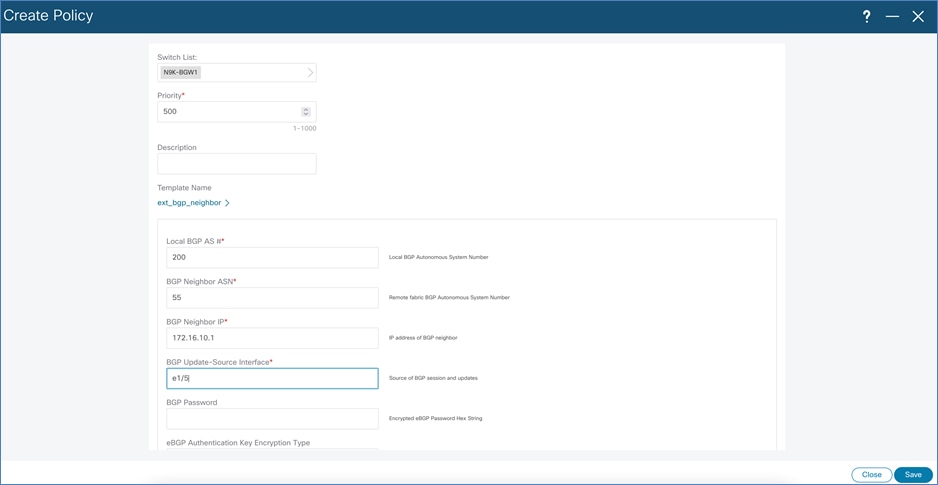
Perform the same action on the other seed switch.
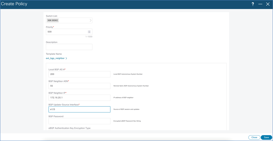
To deploy the configuration, choose Recalculate and Deploy to push out BGP configuration. The BGP config on seeds will be as shown in the following sample.
router bgp 200
neighbor 172.16.10.1
remote-as 55
update-source e1/5
address-family ipv4 unicast
next-hop-self
After the configuration is deployed, BGP neighborship is established between the external router and seed switches.
External# show bgp all summary
BGP summary information for VRF default, address family IPv4 Unicast
BGP router identifier 192.168.1.254, local AS number 55
Neighbor V AS MsgRcvd MsgSent TblVer InQ OutQ Up/Down State/PfxRcd
172.16.10.10 4 200 1658 1700 27 0 0 00:00:42 6
172.16.20.10 4 200 1657 1701 27 0 0 00:00:41 6
BGP summary information for VRF default, address family IPv6 Unicast
External#
The following sample shows the routes received by the external router.
External# show ip routes bgp
IP Route Table for VRF "default"
'*' denotes best ucast next-hop
'**' denotes best mcast next-hop
'[x/y]' denotes [preference/metric]
'%<string>' in via output denotes VRF <string>
10.3.0.1/32, ubest/mbest: 1/0
*via 172.16.20.10, [20/0], 00:00:23, bgp-55, external, tag 200
10.3.0.2/32, ubest/mbest: 1/0
*via 172.16.10.10, [20/0], 00:00:32, bgp-55, external, tag 200
10.4.0.0/30, ubest/mbest: 1/0
*via 172.16.20.10, [20/0], 00:00:23, bgp-55, external, tag 200
10.4.0.4/30, ubest/mbest: 1/0
*via 172.16.20.10, [20/0], 00:00:23, bgp-55, external, tag 200
10.4.0.8/30, ubest/mbest: 1/0
*via 172.16.10.10, [20/0], 00:00:32, bgp-55, external, tag 200
10.4.0.12/30, ubest/mbest: 1/0
*via 172.16.10.10, [20/0], 00:00:32, bgp-55, external, tag 200
External#
Both the seeds advertise their VTEP loopback prefixes (10.3.0.1/32 & 10.3.0.2/32) along with prefixes for their core-facing P2P interfaces from the underlay subnet IP pool (10.4.0.0/16).
If the spine layer devices are powered up and are in POAP loop, they would receive DHCP offers from the seed switches and show on Add Switches > Bootstrap tab.
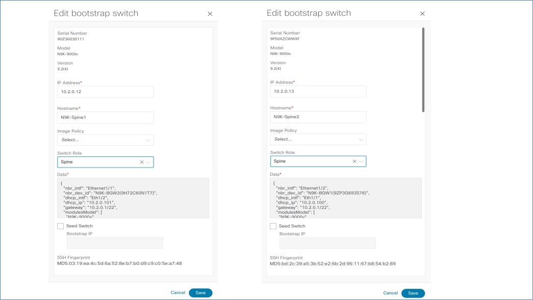
Click Edit to assign permanent IP Address, Hostname, and Switch Role.
When the spine is in POAP loop, it transmits DHCP request on all the links connected to seeds which in-turn is relayed to NDFC. NDFC offers the other IP over DHCP from the subnet configured on respective interfaces of seed switches. If there is more than one seed switch, spine switch receives multiple DHCP offers (one from each seed); however, the first offer on spine is chosen. The corresponding interface is configured with the IP and the respective seed switch becomes the gateway.
In this example, the gateway for both the spines happens to be N9K-BGW1. This can be validated by looking at Data fields in the previous figure. eth1/1 of spine1(9DZ36G3D111) is assigned IP address 10.4.0.14/30 over DHCP which is connected to BGW-1’s eth1/1 (10.4.0.13/30). Similarly, eth1/2 of spine2 (9PS0XZCWWXF) is assigned IP address 10.4.0.10/30 which is connected to BGW-1’s eth1/2 (10.4.0.9/30).
To import these devices, enter Admin password and click Import Selected switches.
The spine switches reload after bootstrap. After the reload, spine switches must be configured with VXLAN-related configuration.
a) Routing and Rendezvous Point (RP) loopbacks
b) Core facing interfaces
c) DHCP Relay on core facing interfaces
d) OSPF enabled on core facing interfaces
e) BGP to form L2VPN EVN neighborship with the seed switches
Note: During the spine’s bootstrap, spine receives offer from both the seeds. However, it only accepts one. The interface connecting to the seed (DHCP offer that was accepted) gets the IP assigned from the same subnet used by the seed. While the interface connecting to the other seed (DHCP offer that was not accepted) gets the IP from a new subnet. This prevents OSPF to come up with this seed due to different IP subnets used on seed and spine switches.
You do not have to perform any configuration at this moment, as this is automatically corrected by NDFC by performing Recalculate and Deploy.
Choose Recalculate and Deploy to correct underlay addressing on link connected to seed (whose offer was not accepted) and push L2VPN EVPN configuration on the seed switches to form neighborship with spines.
The onboarding of spine switches is now complete. It’s now time to bootstrap the leaf devices.
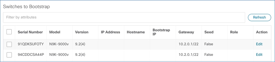
Now, if the leafs are powered on and in POAP loop, they receive DHCP offer from spines and are shown on Add Switches > Bootstrap tab.
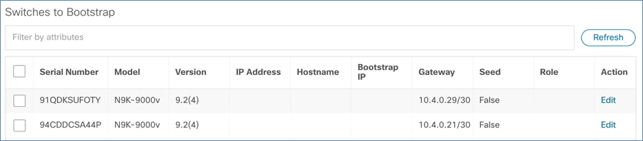
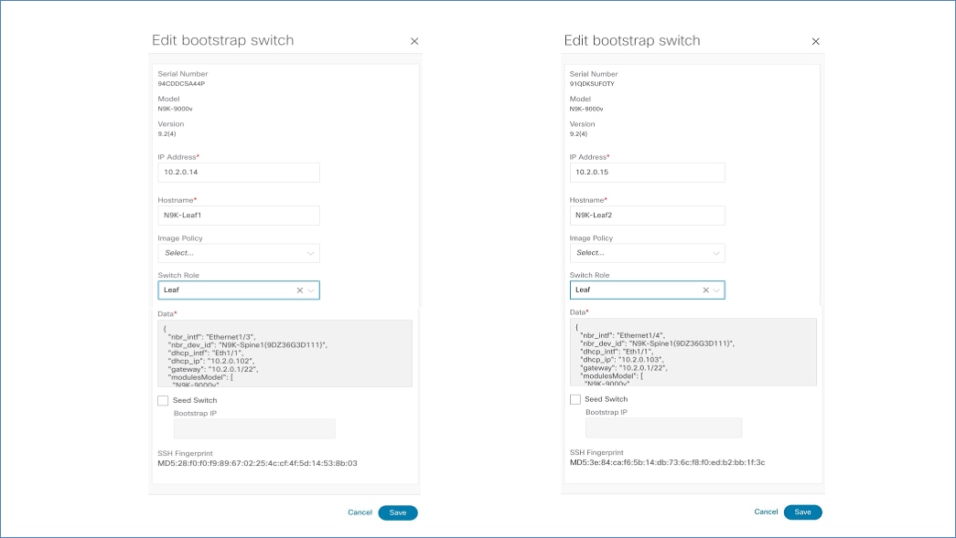
Click Edit to assign Hostname, IP Address, and Switch Role to these leaf devices.
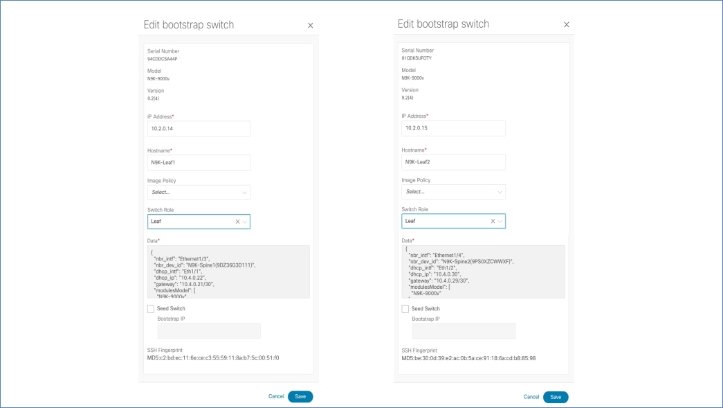
In this example, the gateway for Leaf-1 and Leaf-2 are Spine-1 & Spine-2 respectively. The interfaces of leafs connected to these spines are assigned with other IPs from the same subnet, which is used on the respective spine’s interface.
This can be validated from the Data field in the previous figure. Leaf-1’s eth1/1 gets IP address 10.4.0.22/20 assigned, which is connected to Spine-1’s eth1/3 (10.40.0.21/30). Leaf-2’s eth1/2 gets IP address 10.4.0.30/30 assigned, which is connected to Spine-2’s eth1/4 (10.4.0.29/30).
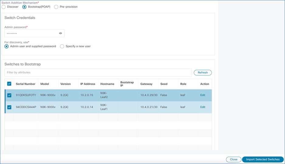
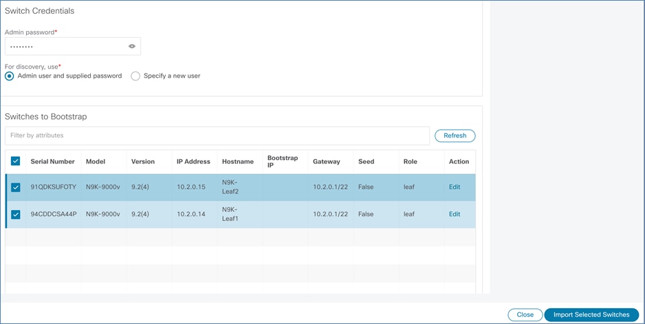
Enter Admin password and select the leaf devices and click Import Selected Switches to import the switches.
The leaf switches reload after bootstrap. After the reload, leaf switches are configured with following VXLAN configuration.
a) Routing and VTEP loopbacks
b) Underlay links connected to spine
c) OSPF for Underlay peering
d) BGP to form L2VPN EVN neighborship with Spines
Note: This topology has two spines, and each leaf has two links connected to spines (one to each spine). However, only one link on each leaf has the IP address assigned over DHCP (depending on DHCP offer accepted on the link). To configure the other link, perform Recalculate and Deploy.
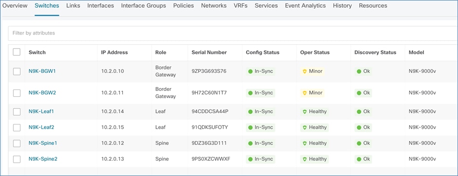
Choose Recalculate and Deploy to configure the remaining spine-facing links on leafs and L2VPN EVPN BGP configuration on spines to form neighborship with leafs. Now, all the devices in fabric are In-Sync status.

We have successfully onboarded all the devices using Inband POAP and VXLAN EVPN fabric is configured. Now, the fabric is ready for any Day1 or Day2 operations.
Inband POAP for IP-Unnumbered Fabric
The following image shows a sample topology for Inband POAP for IP-Unnumbered fabric. All the perquisites, NDFC settings and External router configuration applicable for numbered fabric also applies to unnumbered fabric along with few other settings, as explained in the following section.
Additional Settings for IP-Unnumbered Fabrics
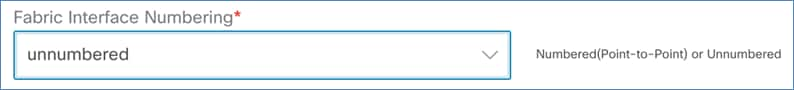
For unnumbered fabric, set the Fabric Interface Numbering to unnumbered under General tab of Fabric Settings.
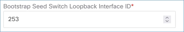
More loopback is required on seed switches, which acts as gateway for DHCP leased IP addresses assigned on downstream devices, during bootstrap process. By default, NDFC uses loopback253 for this purpose. However, you can change by specifying any other loopback number in Bootstrap Seed Switch Loopback Interface ID field on the Bootstrap tab.
All the seed switches share common IP for this loopback. The first IP from IGP/BGP routing subnet pool is assigned to this loopback.
N9K-BGW1# show running configuration interface loopback 253
interface loopback253
description Bootstrap GW loopback interface
ip address 10.2.0.1/32 tag 54321
ip router ospf UNDERLAY area 0.0.0.0
ip pim sparse-mode
N9K-BGW1#
N9K-BGW2# show running configuration interface loopback 253
interface loopback253
description Bootstrap GW loopback interface
ip address 10.2.0.1/32 tag 54321
ip router ospf UNDERLAY area 0.0.0.0
ip pim sparse-mode
N9K-BGW2#
DHCP Lease for Switch Loopbacks
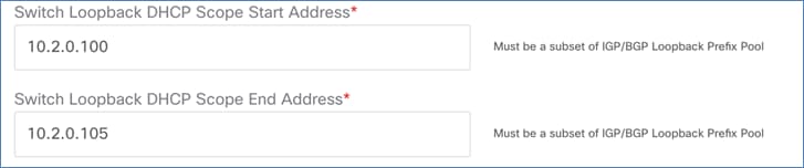
For unnumbered fabric, more DHCP scope is defined from IGP/BGP routing subnet pool. IP Addresses from this scope are leased to the non-seed devices of the fabric during bootstrap process.
The following sample shows log from one of the spines during bootstrap process. It shows the DHCP assigned IP on Spine and the gateway address, which is the bootstrap gateway loopback of the seed.
2022 Jul 11 03:32:27 switch %$ VDC-1 %$ %POAP-2-POAP_INFO: - Abort Power On Auto Provisioning [yes - continue with normal setup, skip - bypass password and basic configuration, no - continue with Power On Auto Provisioning] (yes/skip/no)[no]:
2022 Jul 11 03:32:29 switch %$ VDC-1 %$ %POAP-2-POAP_INFO: Received DHCP offer from server ip - 192.168.1.245
2022 Jul 11 03:32:56 switch %$ VDC-1 %$ %POAP-2-POAP_INFO: [9DZ36G3D111-52:54:00:11:4E:4B] - Using DHCP, valid information received over Eth1/1 from 192.168.1.245
2022 Jul 11 03:32:56 switch %$ VDC-1 %$ %POAP-2-POAP_INFO: [9DZ36G3D111-52:54:00:11:4E:4B] - Assigned IP address: 10.2.0.101
2022 Jul 11 03:32:56 switch %$ VDC-1 %$ %POAP-2-POAP_INFO: [9DZ36G3D111-52:54:00:11:4E:4B] - Netmask: 255.255.252.0
2022 Jul 11 03:32:56 switch %$ VDC-1 %$ %POAP-2-POAP_INFO: [9DZ36G3D111-52:54:00:11:4E:4B] - DNS Server: 171.70.168.183
2022 Jul 11 03:32:56 switch %$ VDC-1 %$ %POAP-2-POAP_INFO: [9DZ36G3D111-52:54:00:11:4E:4B] - Default Gateway: 10.2.0.1
2022 Jul 11 03:32:56 switch %$ VDC-1 %$ %POAP-2-POAP_INFO: [9DZ36G3D111-52:54:00:11:4E:4B] - Script Server: http://192.168.1.246
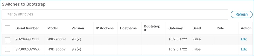
When NDFC fabric is enabled for POAP and seed devices are POAP loop, choose Fabric Overview > Switches > Add Switches on Bootstrap tab to view the seed switches.
POAP on seed layer can be divided into two steps. In Step 1, seed switches are onboarded and in Step 2, eBGP policy is applied on seed switches.
Step 1
The bootstrap process of seed switches for unnumbered fabric is exactly similar to the numbered fabric with few extra steps which are listed below. Refer Step 1 for Numbered fabric for bootstrap of the seed devices.
a) Bootstrap Gateway loopback
b) Static route for IGP/BGP Routing subnet
c) BGP network statement to advertise IGP/BGP subnet
d) Redistribution of AM routes
Bootstrap Gateway loopback
Sample Bootstrap Gateway loopback that is created on both the seed switches sharing same IP address:
interface loopback253
description Bootstrap GW loopback interface
ip address 10.2.0.1/32 tag 54321
ip router ospf UNDERLAY area 0.0.0.0
ip pim sparse-mode
Static route for IGP/BGP Routing subnet
Static routes that are configured for IGP/BGP routing subnet pointing to Null0, so that this subnet are advertised to external router over BGP
ip route 10.2.0.0/22 Null0
BGP Configuration
Unlike the numbered fabric where OSPF and connected routes are redistributed into BGP, with unnumbered fabric connected and AM routes are redistributed.
router bgp 200
router-id 10.2.0.10
address-family ipv4 unicast
network 10.2.0.0/22
redistribute direct route-map fabric-rmap-redist-direct
redistribute am route-map fabric-rmap-redist-am
All other configurations remain the same as for numbered fabric.
Step 2
Apply ext_bgp_neighbor template to both the seeds to form neighborship with the external router (similar to Step 2 in numbered fabric).
After the configuration is deployed, BGP neighborship is established between the external router and the seed switches.
External# show bgp all summary
BGP summary information for VRF default, address family IPv4 Unicast
BGP router identifier 192.168.1.254, local AS number 55
<>
Neighbor V AS MsgRcvd MsgSent TblVer InQ OutQ Up/Down State/PfxRcd
172.16.10.10 4 200 1658 1700 27 0 0 00:00:42 6
172.16.20.10 4 200 1657 1701 27 0 0 00:00:41 6
BGP summary information for VRF default, address family IPv6 Unicast
External#
Sample routes received by the External router are as follows:
External# show ip route bgp
IP Route Table for VRF "default"
'*' denotes best ucast next-hop
'**' denotes best mcast next-hop
'[x/y]' denotes [preference/metric]
'%<string>' in via output denotes VRF <string>
10.2.0.0/22, ubest/mbest: 2/0
*via 172.16.10.10, [20/0], 01:06:57, bgp-55, external, tag 200
*via 172.16.20.10, [20/0], 01:06:54, bgp-55, external, tag 200
10.2.0.1/32, ubest/mbest: 2/0
*via 172.16.10.10, [20/0], 01:06:57, bgp-55, external, tag 200
*via 172.16.20.10, [20/0], 01:06:54, bgp-55, external, tag 200
10.3.0.1/32, ubest/mbest: 1/0
*via 172.16.20.10, [20/0], 01:06:54, bgp-55, external, tag 200
10.3.0.2/32, ubest/mbest: 1/0
*via 172.16.10.10, [20/0], 01:06:57, bgp-55, external, tag 200
External#
10.2.0.0/22 prefix is for IGP/BGP loopback, which is advertised by both the seed devices.
10.2.0.1/32 prefix is for the IP address, which is configured on Bootstrap GW loopback on both the seeds sharing same IP.
10.3.0.x/32 prefixes are for the VTEP loopbacks, which are advertised by the respective seed switches.
If the Spine layer devices are powered on and in POAP loop, they would receive DHCP offers from NDFC and show up under Bootstrap tab of Add Switches in NDFC –
If the spine layer devices are powered up and are in POAP loop, they would receive DHCP offers from NDFC and show on Add Switches > Bootstrap tab.
Before onboarding, assign permanent IP Address, Hostname, and Switch Role.
The spine switches receive DHCP offers from both the seeds. However, it only accepts from one of the seed switches. The seed (whose DHCP offer was accepted) acts as gateway for the spine and is responsible for advertising prefix (for DHCP assigned IP on spine) to external router. This prefix is learned over AM (Adjacency Manager) process on seed as an Adjacency route (/32).
From Data field, we can validate the gateway for the spines. In this example, gateway for spine1 is BGW2 and for spine2 its BGW1.
The following sample output shows the AM routes generated by the respective seeds, which are being advertised to external router over BGP.
N9K-BGW1# show ip route am
10.2.0.100/32, ubest/mbest: 1/0, attached
*via 10.2.0.100, Eth1/2, [250/0], 00:08:55, am
172.16.10.1/32, ubest/mbest: 1/0, attached
*via 172.16.10.1, Eth1/5, [250/0], 00:08:55, am
N9K-BGW1#
N9K-BGW2# show ip route am
10.2.0.101/32, ubest/mbest: 1/0, attached
*via 10.2.0.101, Eth1/1, [250/0], 00:09:20, am
172.16.20.1/32, ubest/mbest: 1/0, attached
*via 172.16.20.1, Eth1/5, [250/0], 00:09:20, am
N9K-BGW2#
External# show ip route bgp
IP Route Table for VRF "default"
'*' denotes best ucast next-hop
'**' denotes best mcast next-hop
'[x/y]' denotes [preference/metric]
'%<string>' in via output denotes VRF <string>
10.2.0.0/22, ubest/mbest: 2/0
*via 172.16.10.10, [20/0], 00:34:31, bgp-55, external, tag 200
*via 172.16.20.10, [20/0], 00:34:28, bgp-55, external, tag 200
10.2.0.1/32, ubest/mbest: 2/0
*via 172.16.10.10, [20/0], 00:34:31, bgp-55, external, tag 200
*via 172.16.20.10, [20/0], 00:34:28, bgp-55, external, tag 200
10.2.0.100/32, ubest/mbest: 1/0
*via 172.16.10.10, [20/0], 00:34:31, bgp-55, external, tag 200
10.2.0.101/32, ubest/mbest: 1/0
*via 172.16.20.10, [20/0], 00:34:28, bgp-55, external, tag 200
10.3.0.1/32, ubest/mbest: 1/0
*via 172.16.20.10, [20/0], 00:34:28, bgp-55, external, tag 200
10.3.0.2/32, ubest/mbest: 1/0
*via 172.16.10.10, [20/0], 00:34:31, bgp-55, external, tag 200
External#
Enter the Admin password and click Import Selected switches.
The spine devices downloads POAP script and reloads. After the spines are reloaded, choose Recalculate and Deploy to push BGP config on seeds to form IPv4 and L2VPN EVPN address families peering with spines.
For IP-unnumbered fabric, apart from forming BGP L2VPN EVPN neighborship, IPv4 peering is also required between spine and seed/leaf devices, as prefixes for downstream devices are learned as AM routes (generated by ARP), and BGP is the only protocol which supports redistribution of AM routes.
Note that for numbered fabric, there is no need of AM routes as each underlay interface is assigned with an IP address that is advertised by OSPF.
Note: This is a mandatory step to complete POAP operation for downstream devices.
When the leaf switches are powered on and devices are in POAP loop, on the NDFC Web UI, choose Fabric Overview > Switches > Add Switches. The leaf switches appear on the Bootstrap tab.
Click Edit to provide permanent IP Address, Hostname, Switch Role. Click Save to begin onboarding.
After the leafs are reloaded, choose Recalculate and Deploy to push BGP configuration on spines to form IPv4 and L2VPN EVPN peering with leafs.
Now, all the devices in fabric are In-Sync status.
Now, the fabric is ready for any Day1 or Day2 operations.
Cisco Nexus Dashboard Fabric Controller (NDFC) is a comprehensive data center automation tool for building LAN/SAN/IPFM fabrics. With support for both Inband and OOB POAP, the whole fabric can be brought up without any manual configuration on the devices using the console. After the devices are racked up and connected, they can be controlled and configured completely from NDFC allowing Zero-touch provisioning of the fabrics, thus reducing overall time and effort in building new fabrics.
Cisco and the Cisco logo are trademarks or registered trademarks of Cisco and/or its affiliates in the U.S. and other countries. To view a list of Cisco trademarks, go to this URL: http://www.cisco.com/go/trademarks. Third-party trademarks mentioned are the property of their respective owners. The use of the word partner does not imply a partnership relationship between Cisco and any other company. (1721R)
Any Internet Protocol (IP) addresses and phone numbers used in this document are not intended to be actual addresses and phone numbers. Any examples, command display output, network topology diagrams, and other figures included in the document are shown for illustrative purposes only. Any use of actual IP addresses or phone numbers in illustrative content is unintentional and coincidental.
© 2022 Cisco Systems, Inc. All rights reserved.