-
Installation and Upgrade Guide for Cisco Unified MeetingPlace Audio Server Release 5.4
-
Index
-
Preface
-
Preparing to Install the Cisco Unified MeetingPlace 8100 Series Hardware
-
Installing the Cisco Unified MeetingPlace 8100 Series Hardware
-
Connecting and Setting Up Your Laptop Computer
-
Upgrading the Cisco Unified MeetingPlace Audio Server Software
-
Testing the Cisco Unified MeetingPlace Audio Server System Installation and Upgrade
-
Maintaining the Cisco Unified MeetingPlace Audio Server System
-
Troubleshooting the Cisco Unified MeetingPlace Audio Server System Installation
-
Appendix: Cisco Unified MeetingPlace Audio Server Software Upgrade Reference
-
 Feedback
Table Of Contents
Installing the Cisco Unified MeetingPlace 8100 Series Hardware
Contents of Shipped Boxes for the Cisco Unified MeetingPlace Audio Server System
Mounting the Cisco Unified MeetingPlace 8100 Series
Mounting the Cisco Unified MeetingPlace 8106 in a 19-Inch Frame-Relay Rack
Mounting the Cisco Unified MeetingPlace 8112 in a 19- or 23-Inch Frame-Relay Rack
Mounting the Cisco Unified MeetingPlace 8106 in a 19-Inch EIA Equipment Rack
Mounting the Cisco Unified MeetingPlace 8112 into a 19- or 23-Inch EIA Equipment Rack
Mounting the Breakout Box for T1 PRI and E1 Cisco Unified MeetingPlace Systems
Connecting the Cables to the Cisco Unified MeetingPlace 8100 Series
Connecting the Power Cable to the Cisco Unified MeetingPlace 8100 Series
Connecting the SCSI Cable to the Cisco Unified MeetingPlace 8112
Connecting the LAN Cable to the Cisco Unified MeetingPlace 8100 Series
Connecting T1 CAS Telephony Cables for a Cisco Unified MeetingPlace 8106
Connecting T1 CAS Telephony Cables for a Cisco Unified MeetingPlace 8112
About Telephony Configurations for E1 and T1 PRI Cisco Unified MeetingPlace Systems
Connecting E1 or T1 PRI Telephony Cables with One Multi Access Blade MP-MA-16-PRI
Connecting E1 or T1 PRI Telephony Cables with One Multi Access Blade MP-MA-4-PRI
Connecting E1 or T1 PRI Telephony Cables with Two Multi Access Blade MP-MA-4-PRIs
Connecting E1 or T1 PRI Telephony Cables with Two Multi Access Blade MP-MA-16-PRIs
About Telephony Configurations for IP Cisco Unified MeetingPlace Systems
Connecting IP Telephony Cables for Cisco Unified MeetingPlace Systems
About Telephony Configurations for Mixed Cisco Unified MeetingPlace Systems
Connecting the Telephony Cables for an E1/IP or T1 PRI/IP Cisco Unified MeetingPlace System
Connecting the Telephony Cables for a T1 CAS/IP Cisco Unified MeetingPlace System
Installing and Connecting the Modem
Installing the Cisco Unified MeetingPlace 8100 Series Hardware
CautionIf your current Cisco Unified MeetingPlace Audio Server uses IRCs and you are upgrading to Audio Server Release 5.4, you must get new hardware. Audio Server 5.4 does not support IRCs.
This chapter contains the following sections:
•
•
•
•
•
•
•
Contents of Shipped Boxes for the Cisco Unified MeetingPlace Audio Server System
All Cisco Unified MeetingPlace Audio Server systems ship in two boxes. One box contains the Cisco Unified MeetingPlace Audio Server and its accessories. The other box contains the telephony cables, modem and modem cables, and the breakout box and cables, if applicable.
Cisco Systems provides the correct number of telephony cables for the Cisco Unified MeetingPlace system:
•
•
•
•
The following items are also included in the boxes:
•
Cisco Unified MeetingPlace Audio Server software is installed on the Cisco Unified MeetingPlace 8100 series server in manufacturing, so you do not need to install Audio Server software. The server should already be configured with the correct cards and transition modules as well. If it is not, contact Cisco TAC.
Caution
The Cisco Unified MeetingPlace 8112, its peripherals, and the packing materials can weigh up to 130 lbs (59 kg).
•
–
–
•
•
•
•
•
•
•
•
•
In addition, Cisco Systems ships the following items with Cisco Unified MeetingPlace systems requiring a breakout box (T1 PRI or E1 configuration):
•
•
•
Mounting the Cisco Unified MeetingPlace 8100 Series
Before mounting the Cisco Unified MeetingPlace Audio Server in a rack, confirm that you have met all the requirements in the "Environmental Requirements for the Cisco Unified MeetingPlace 8106" section or the "Environmental Requirements for the Cisco Unified MeetingPlace 8112" section.
The Cisco Unified MeetingPlace 8100 series servers can be mounted in two types of racks:
•
See the "Mounting the Cisco Unified MeetingPlace 8106 in a 19-Inch Frame-Relay Rack" section.
•
See the "Mounting the Cisco Unified MeetingPlace 8106 in a 19-Inch EIA Equipment Rack" section.
•
See the "Mounting the Cisco Unified MeetingPlace 8112 in a 19- or 23-Inch Frame-Relay Rack" section.
•
See the "Mounting the Cisco Unified MeetingPlace 8112 into a 19- or 23-Inch EIA Equipment Rack" section.
When mounting the Cisco Unified MeetingPlace Audio Server in a Frame-Relay rack, which is common in central office locations, the Cisco Unified MeetingPlace 8106 is held along the front of the chassis and the Cisco Unified MeetingPlace 8112 is held along the center of the chassis.
After mounting the Cisco Unified MeetingPlace Audio Server, mount the breakout box, if applicable. See the "Mounting the Breakout Box for T1 PRI and E1 Cisco Unified MeetingPlace Systems" section.
Mounting the Cisco Unified MeetingPlace 8106 in a 19-Inch Frame-Relay Rack
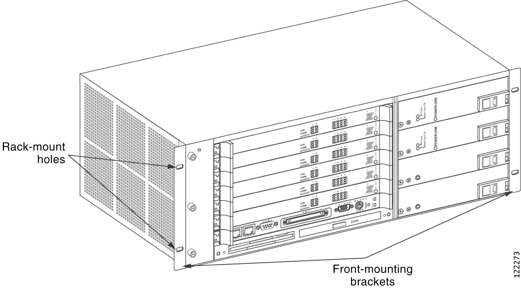
The Cisco Unified MeetingPlace 8106 ships with two mounting brackets already attached to the front of it (see Figure 2-1). The long sides of the brackets are fastened to the Cisco Unified MeetingPlace 8106.
To Mount the Cisco Unified MeetingPlace 8106 in a 19-Inch Frame-Relay Rack
Step 1
Step 2
Figure 2-1 Mounting the Cisco Unified MeetingPlace 8106 in a Frame-Relay Rack
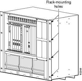
Mounting the Cisco Unified MeetingPlace 8112 in a 19- or 23-Inch Frame-Relay Rack
To Mount the Cisco Unified MeetingPlace 8112 in a 19- or 23-Inch Frame-Relay Rack
Step 1
•
•
Step 2
Step 3
Step 4
•
•
Step 5
Figure 2-2 Mounting the Cisco Unified MeetingPlace 8112 in a Frame-Relay Rack
Mounting the Cisco Unified MeetingPlace 8106 in a 19-Inch EIA Equipment Rack
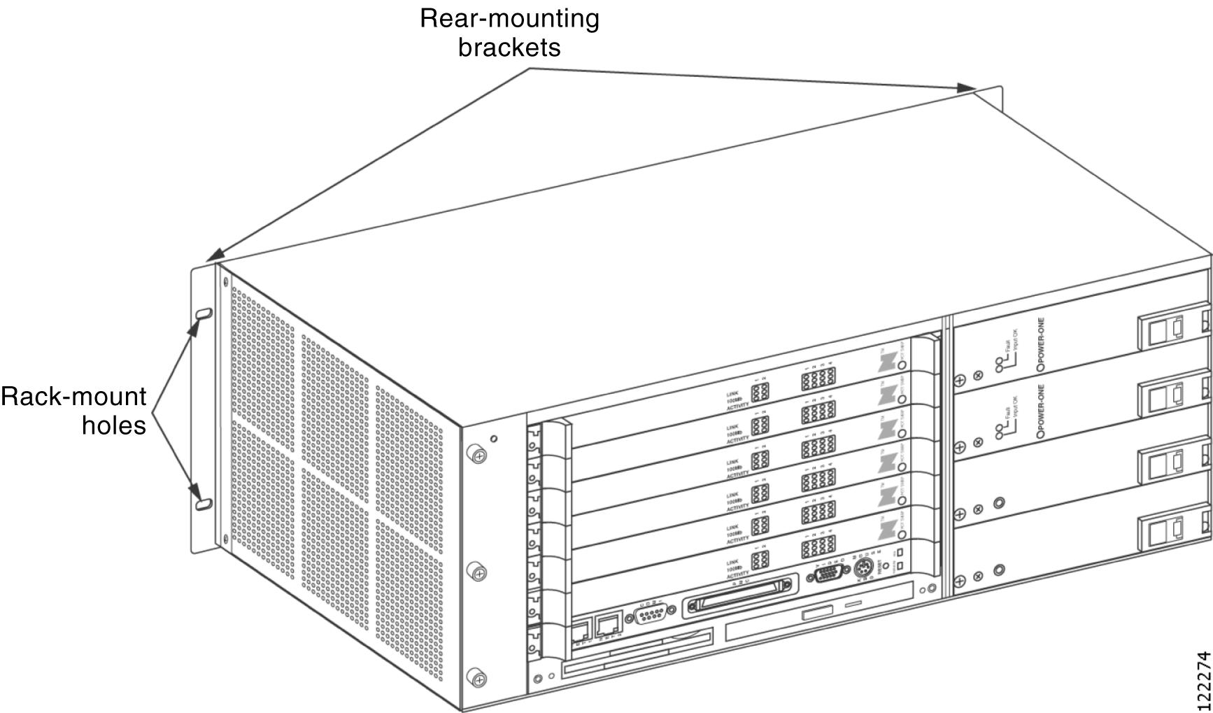
In a 19-inch EIA equipment rack, you mount the Cisco Unified MeetingPlace 8106 on the back rails. The Cisco Unified MeetingPlace 8106 ships with two mounting brackets already attached to the front (see Figure 2-3).
To Mount the Cisco Unified MeetingPlace 8106 in a 19-Inch EIA Equipment Rack
Step 1
Step 2
Step 3
Step 4
Step 5
Step 6
Figure 2-3 Mounting the Cisco Unified MeetingPlace 8106 in an EIA Equipment Rack
Mounting the Cisco Unified MeetingPlace 8112 into a 19- or 23-Inch EIA Equipment Rack
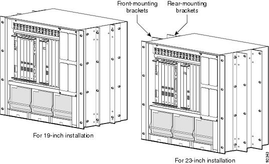
In a 19- or 23-inch EIA equipment rack, you mount the Cisco Unified MeetingPlace 8112 on the front rails.
To Mount the Cisco Unified MeetingPlace 8112 into a 19- or 23-Inch EIA Equipment Rack
Step 1
If you are installing the Cisco Unified MeetingPlace 8112 in a 23-inch rack, you must obtain extension brackets from the rack manufacturer. Install the optional extender brackets as described by the rack manufacturer.
Step 2
Step 3
Figure 2-4 Mounting the Cisco Unified MeetingPlace 8112 into an EIA Equipment Rack
Mounting the Breakout Box for T1 PRI and E1 Cisco Unified MeetingPlace Systems
Note
The breakout box provides a standard RJ-45 telephony interface. The breakout box interfaces to a maximum of 16 cables with an MP-MA-16-PRI and a maximum of 4 cables with each MP-MA-4-PRI. Cisco Systems ships the necessary number of RJ-48c cables to connect each breakout box to your PBX or Telco NIU with each Multi Access Blade.
Note
Cisco Systems also ships the necessary number of 50-pin Amphenol cables with the breakout box: two 50-pin Amphenol cables to connect each MP-MA-16-PRI to the breakout box and one 50-pin Amphenol cable to connect each MP-MA-4-PRI to the breakout box.
If the Cisco Unified MeetingPlace system requires two MP-MA-16-PRIs, you need two breakout boxes. (A fully loaded 960-port E1 Cisco Unified MeetingPlace system and a fully loaded 736-port T1 PRI Cisco Unified MeetingPlace system have two MP-MA-16-PRIs.)
Note
To Mount the Breakout Box for a T1 PRI or E1 Cisco Unified MeetingPlace System
Step 1
Step 2
Step 3
See Figure 2-5.
See Figure 2-6.
Step 4
Figure 2-5 Mounting the Breakout Box for a Cisco Unified MeetingPlace 8106
Figure 2-6 Mounting the Breakout Box for a Cisco Unified MeetingPlace 8112
Figure 2-7 Mounting Two Breakout Boxes for a Cisco Unified MeetingPlace 8112
Connecting the Cables to the Cisco Unified MeetingPlace 8100 Series
This section contains the following information:
•
•
•
•
•
Connecting the Power Cable to the Cisco Unified MeetingPlace 8100 Series
Warning
Warning
To Connect the Power Cable to the Cisco Unified MeetingPlace 8100 Series
Step 1
Step 2
Step 3
Connecting the SCSI Cable to the Cisco Unified MeetingPlace 8112
Note
To Connect the SCSI Cable to the Cisco Unified MeetingPlace 8112
Step 1
Step 2
Step 3
Connecting the LAN Cable to the Cisco Unified MeetingPlace 8100 Series
You must supply the LAN cable to connect the Cisco Unified MeetingPlace Audio Server to the network. See the "LAN Requirements for Cisco Unified MeetingPlace Systems" section to confirm that you have the correct LAN cable and connector.
To Connect the LAN Cable to the Cisco Unified MeetingPlace 8100 Series
Step 1
Step 2
Step 3
Connecting T1 CAS Telephony Cables for a Cisco Unified MeetingPlace 8106
Each T1 Smart Blade transition module has connectors for four trunk lines in the back of the Cisco Unified MeetingPlace Audio Server.
Looking at the back of the Cisco Unified MeetingPlace 8106, the T1 Smart Blade transition modules begin in slot 1 on the bottom and move up to the top. The cables go from right to left on the bottom slot, then from right to left on the second most bottom slot, and so on up to the top slot, where they continue going from right to left.
Table 2-1 shows the order in which the cables should be placed.
The number of T1 CAS telephony cables that Cisco Systems ships with the Cisco Unified MeetingPlace system depends on the number of ports being activated. Cisco Systems ships one T1 CAS telephony cable for every 24 ports.
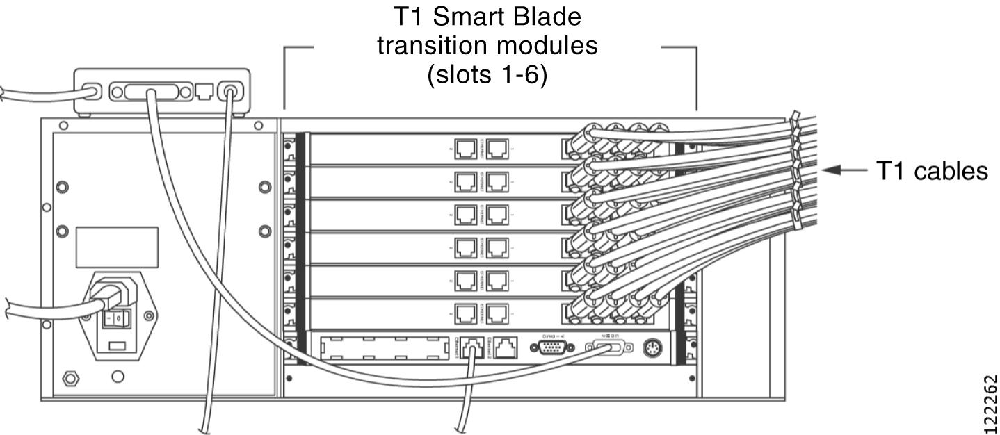
Figure 2-8 shows the cable connections for a Cisco Unified MeetingPlace 8106 with 576 T1 CAS ports. Four T1 CAS telephony cables connect to each of the six T1 Smart Blade transition modules for a total of 24 T1 CAS telephony cables. Each cable holds 24 ports for a total of 576 ports (24 x 24 = 576).
Figure 2-8 Back of Cisco Unified MeetingPlace 8106 with T1s Connected
To Connect the T1 CAS Telephony Cables for a Cisco Unified MeetingPlace 8106
Step 1
Step 2
Step 3
Step 4
a.
b.
c.
Step 5
Connecting T1 CAS Telephony Cables for a Cisco Unified MeetingPlace 8112
Each T1 Smart Blade transition module has connectors for four trunk lines in the back of the Cisco Unified MeetingPlace Audio Server.
Looking at the back of the Cisco Unified MeetingPlace Audio Server, the T1 Smart Blade transition modules begin in slot 1 on the right and move to the left. The cables go from top to bottom in the right most slot, then from top to bottom in the second most right slot, and so on to the left most slot, where they continue going from top to bottom.
Table 2-2 shows the order in which the cables should be placed. Note that slots 7 to 10 are reserved.
The number of T1 CAS telephony cables that Cisco Systems ships with the Cisco Unified MeetingPlace system depends on the number of ports being activated. Cisco Systems ships one T1 CAS telephony cable for every 24 ports.
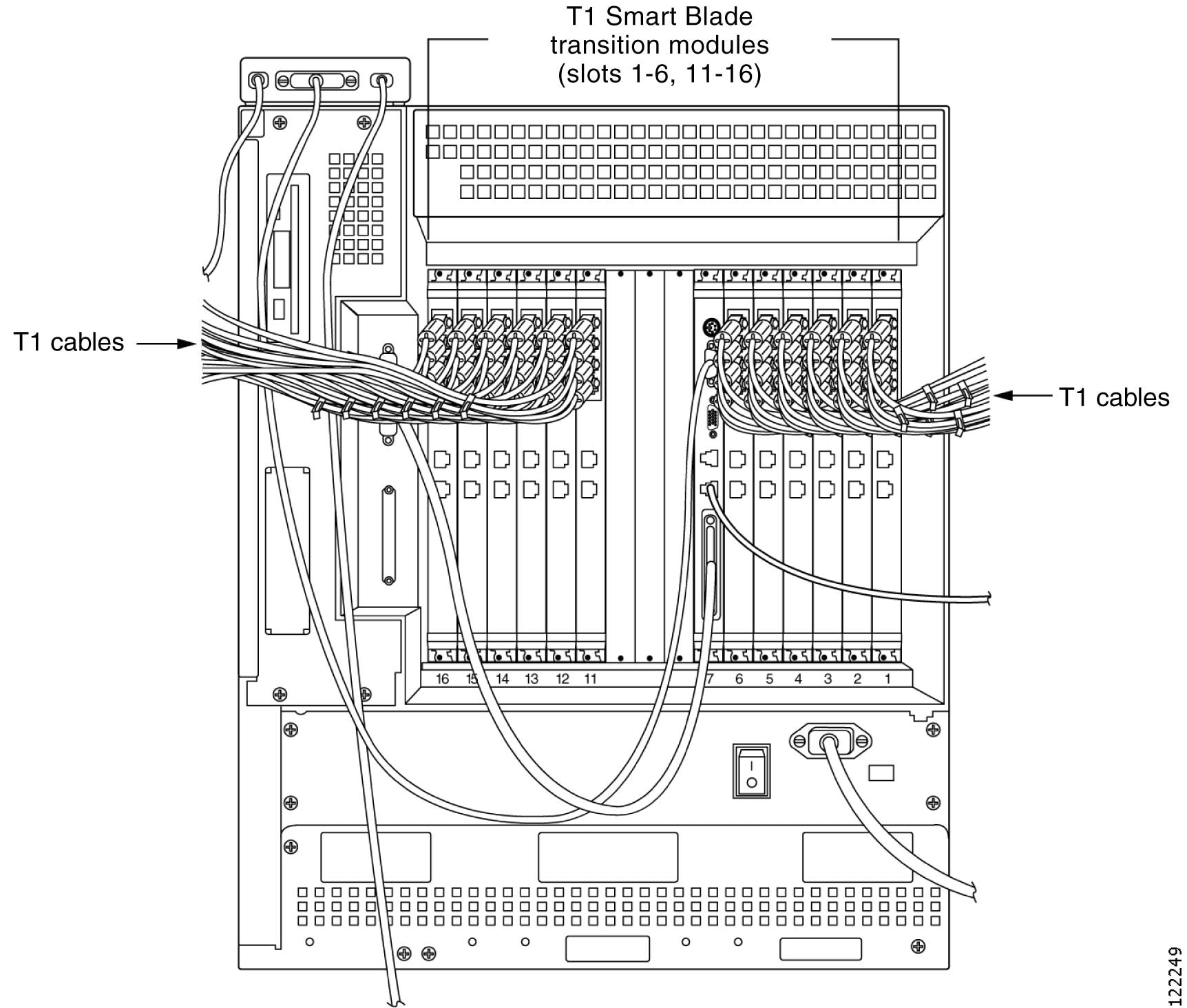
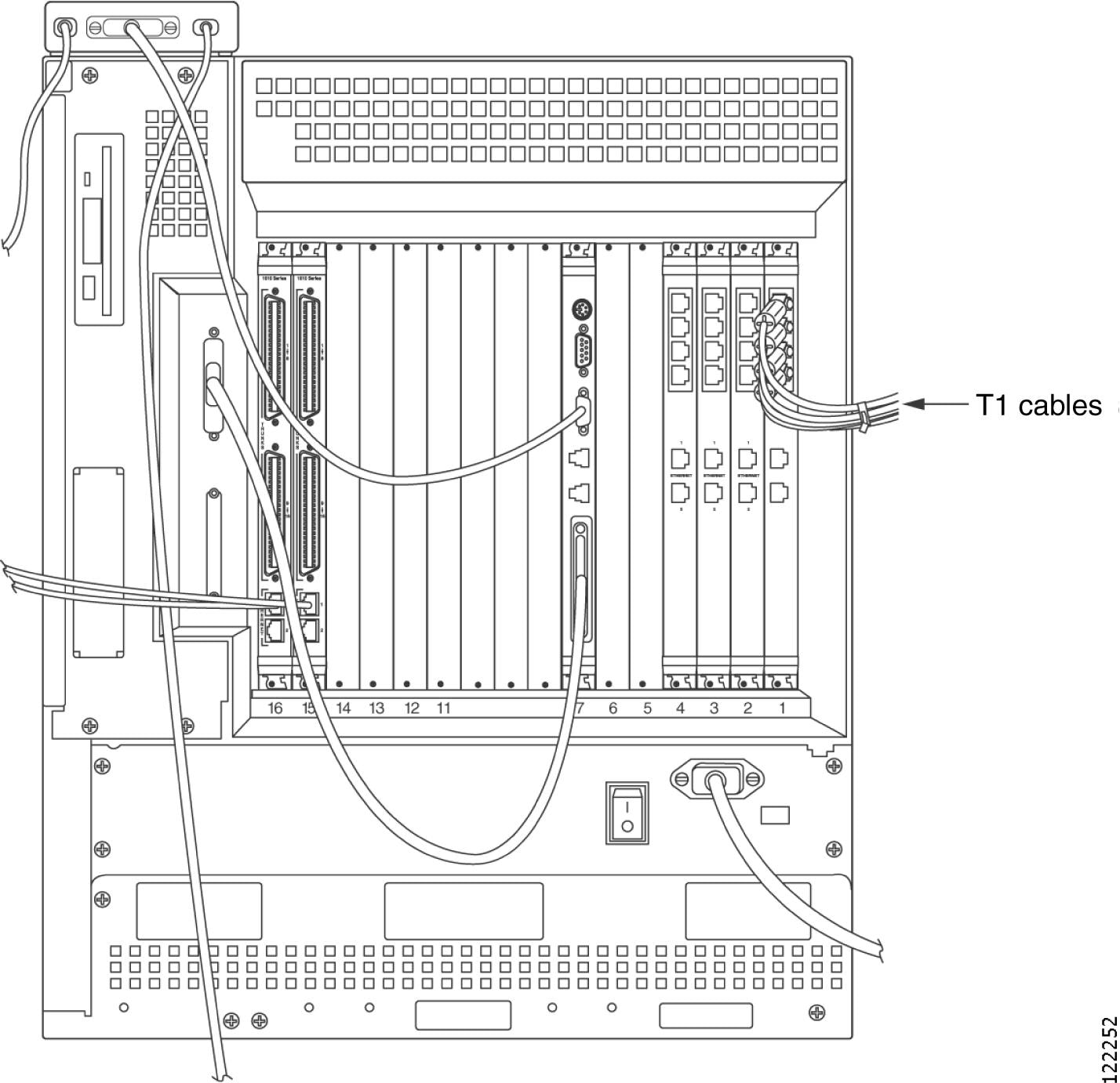
Figure 2-9 shows the cable connections for a Cisco Unified MeetingPlace 8112 with 1,152 T1 CAS ports. Four T1 CAS telephony cables connect to each of the 12 T1 Smart Blade transition modules for a total of 48 T1 CAS telephony cables. Each cable holds 24 ports for a total of 1,152 ports (48 x 24 = 1,152).
Figure 2-9 Back of Cisco Unified MeetingPlace 8112 Audio Server with T1s Connected
To Connect the T1 CAS Telephony Cables for a Cisco Unified MeetingPlace 8112
Step 1
Step 2
Step 3
Step 4
a.
b.
c.
Step 5
About Telephony Configurations for E1 and T1 PRI Cisco Unified MeetingPlace Systems
Cisco Systems ships the necessary number of Multi Access Blades with all Cisco Unified MeetingPlace Audio Server systems with E1 and T1 PRI configurations. A Cisco Unified MeetingPlace 8106 supports three Multi Access Blade configurations, and a Cisco Unified MeetingPlace 8112 supports five configurations:
Cisco Unified MeetingPlace Audio Servers with E1 and T1 PRI configurations also ship with either one or two breakout boxes and cables, depending on the Cisco Unified MeetingPlace system configuration.
Note
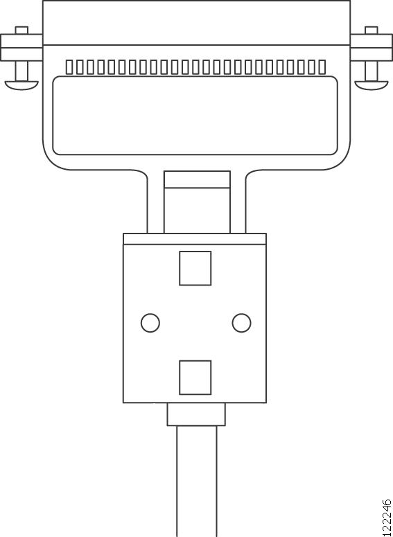
The breakout box provides a standard RJ-45 telephony interface for E1 and T1 PRI Cisco Unified MeetingPlace systems. Cisco Systems ships the necessary number of trunk card interface cable assemblies (50-pin Amphenol cables) that connect the breakout box to the Multi Access Blade transition modules. Figure 2-10 shows the 50-pin Amphenol cable.
Figure 2-10 50-Pin Amphenol Cable
Cisco Systems ships the necessary number of E1 or T1 PRI telephony cables with the Cisco Unified MeetingPlace Audio Server system. The number depends on the number of ports being activated. You receive one E1 telephony cable for every 30 ports in an E1 Cisco Unified MeetingPlace system, and one T1 PRI telephony cable for every 23 ports in a T1 PRI Cisco Unified MeetingPlace system.
Looking at the back of the Cisco Unified MeetingPlace 8106, the Multi Access Blade transition modules begin in slot 1 on the bottom and move up to slot 6 at the top.
Looking at the back of the Cisco Unified MeetingPlace 8112, the Multi Access Blade transition modules begin in slot 1 on the right and move to the left.
The Smart Blades begin after the last Multi Access Blade and do not have any cables connected to them.
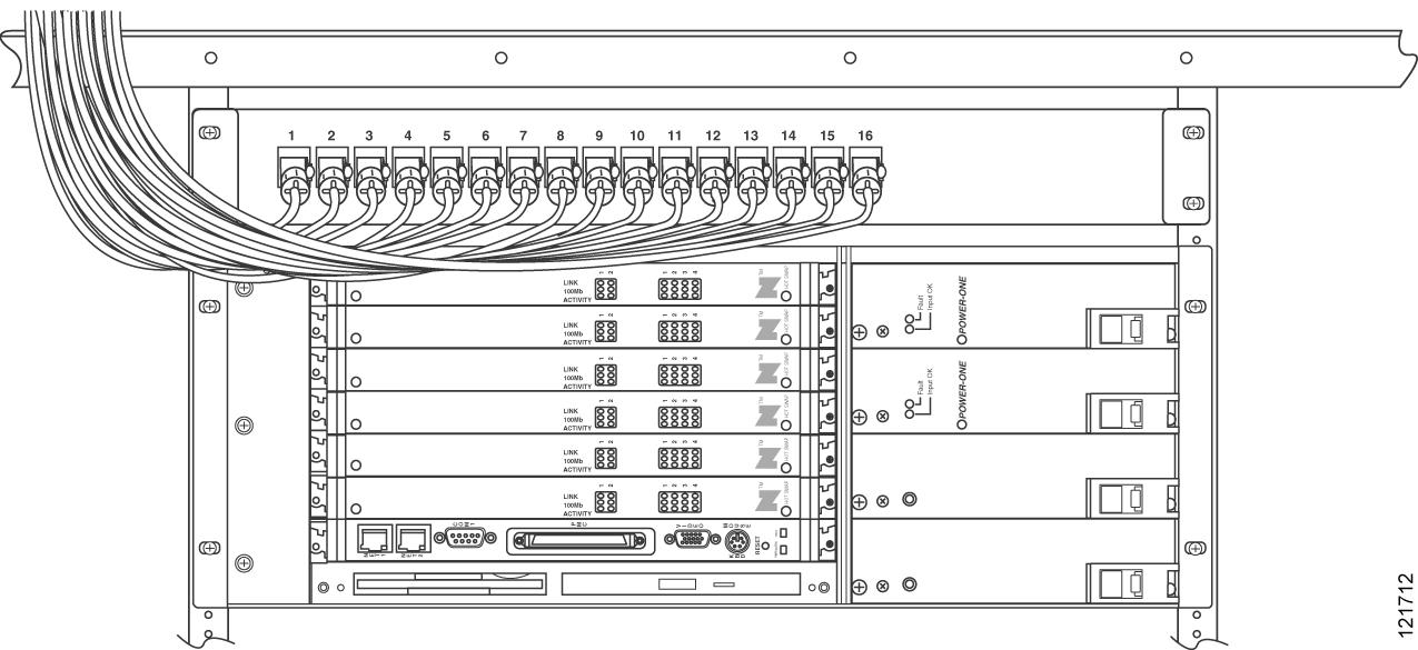
Figure 2-11 shows the cable connections for a Cisco Unified MeetingPlace 8106 with 480 E1 ports.
Figure 2-11 Front of Cisco Unified MeetingPlace 8106 with Cables Connected
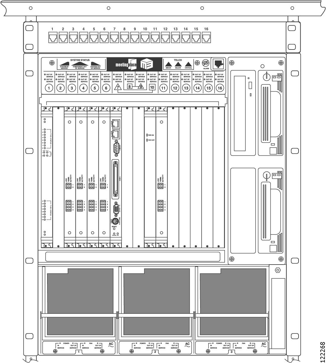
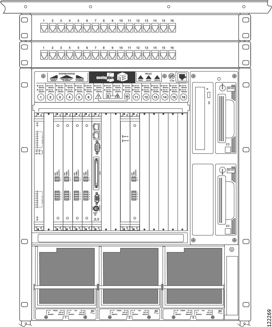
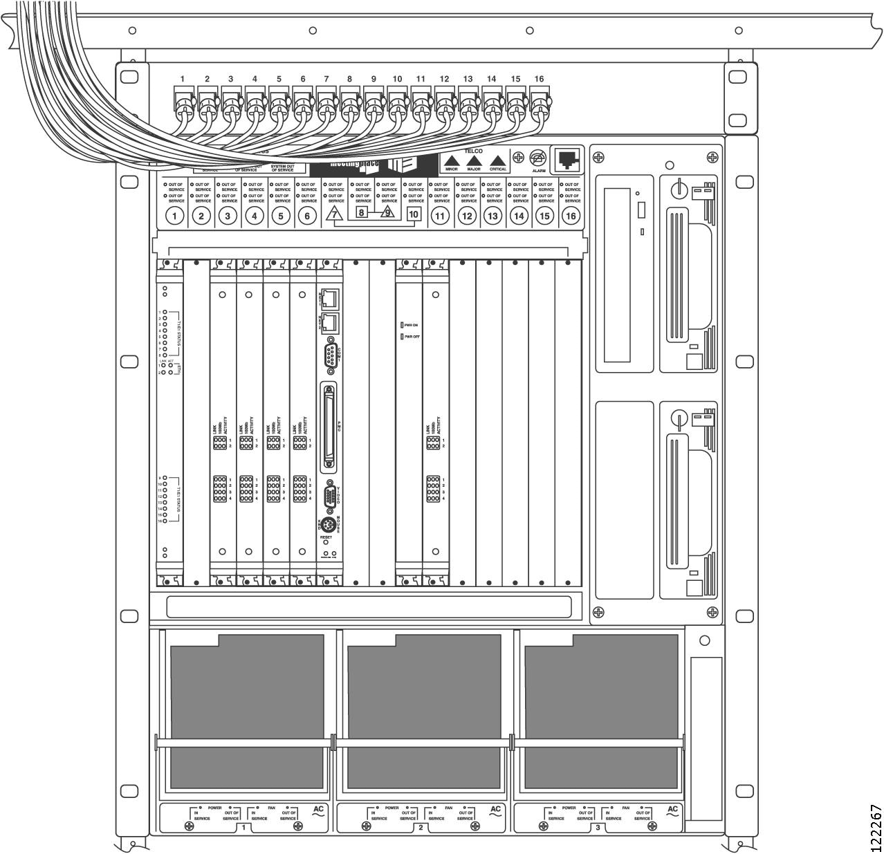
Figure 2-12 shows the cable connections for a Cisco Unified MeetingPlace 8112 with 480 E1 ports.
Figure 2-12 Front of Cisco Unified MeetingPlace 8112 with Cables Connected
See the applicable section for your configuration:
•
•
•
•
Connecting E1 or T1 PRI Telephony Cables with One Multi Access Blade MP-MA-16-PRI
To Connect the E1 or T1 PRI Telephony Cables with One Multi Access Blade MP-MA-16-PRI
Step 1
•
•
•
Step 2
In many cases, the other equipment has an RJ-48c socket in which to plug the E1 or T1 PRI telephony cable. Alternately, the other equipment will be connected to a punchdown block. In this case, you will need to determine the block's connection diagram and then connect to it with discrete wires from the cable.
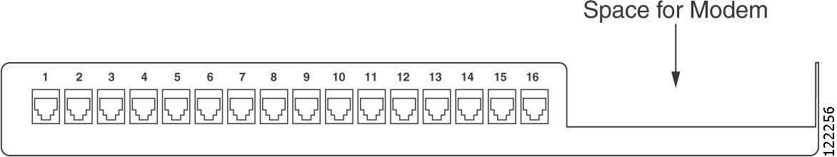
Step 3
Figure 2-13 Breakout Box (Front View)
Step 4
Step 5
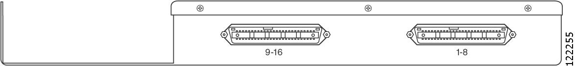
Looking at the back of the breakout box, the connector on the right of the breakout box is for spans 1 to 8, and the connector on the left of the breakout box is for spans 9 to 16. Place the first trunk card cable assembly into the connector on the right. See Figure 2-14.
Figure 2-14 Breakout Box (Back View)
Step 6
For the Cisco Unified MeetingPlace 8106, the connector on the right of the Multi Access Blade transition module is for spans 1 to 8 and the connector on the left of the Multi Access Blade transition module is for spans 9 to 16. Place the first trunk card cable assembly into the connector on the right. See Figure 2-15.
Figure 2-15 Multi Access Blade Transition Module (Cisco Unified MeetingPlace 8106)
For the Cisco Unified MeetingPlace 8112, the connector on the top of the Multi Access Blade transition module is for spans 1 to 8 and the connector on the bottom of the Multi Access Blade transition module is for spans 9 to 16. Place this first trunk card cable assembly into the connector on the top. See Figure 2-16.
Figure 2-16 Multi Access Blade Transition Module (Cisco Unified MeetingPlace 8112)
Step 7
For the Cisco Unified MeetingPlace 8106, place the second trunk card cable assembly into the connectors on the left of the breakout box and on the left of the Multi Access Blade.
For the Cisco Unified MeetingPlace 8112, place the second trunk card cable assembly into the connectors on the left of the breakout box and on the bottom of the Multi Access Blade.
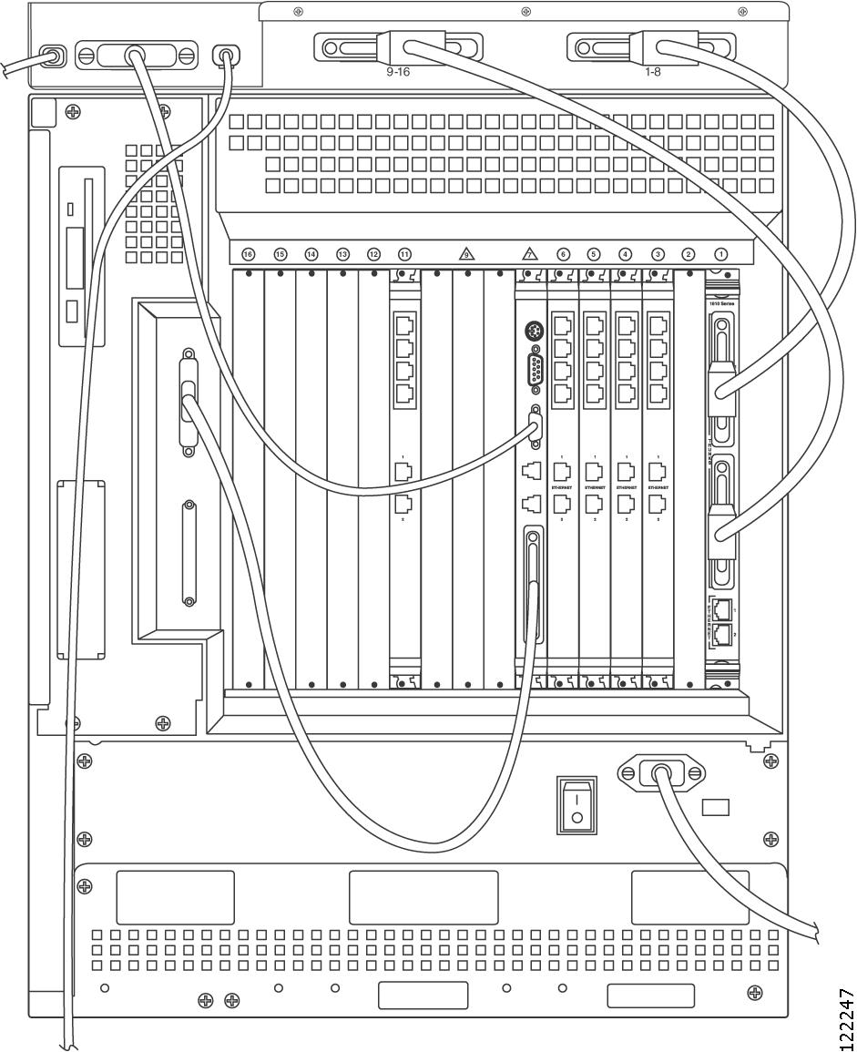
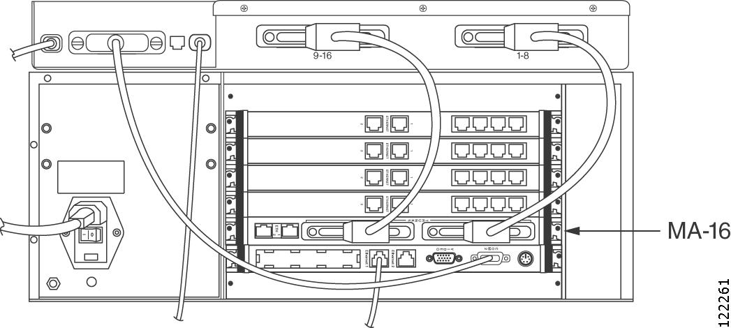
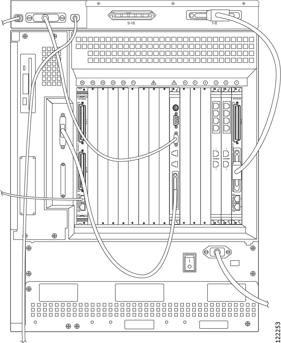
Figure 2-17 shows the connections on the back of a Cisco Unified MeetingPlace 8106. This configuration supports 480 E1 ports with one Multi Access Blade card MP-MA-16-PRI.
Figure 2-17 Back of Cisco Unified MeetingPlace 8106 (E1 with 1 MP-MA-16-PRI)
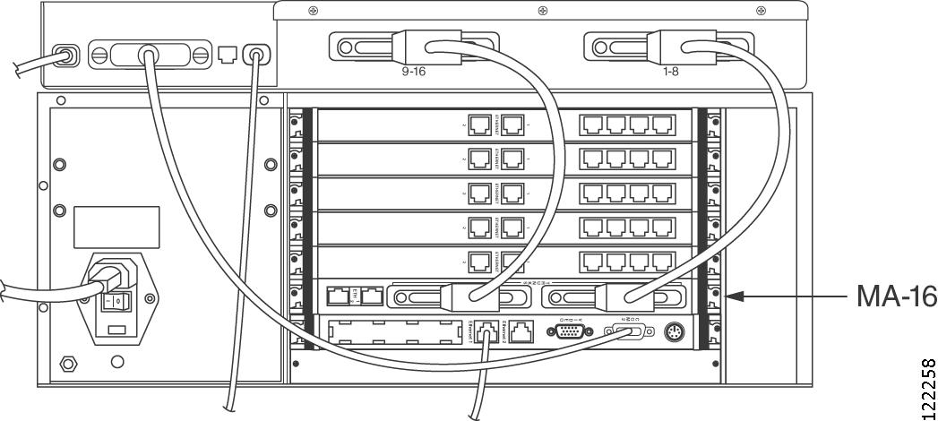
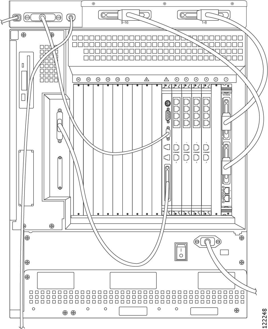
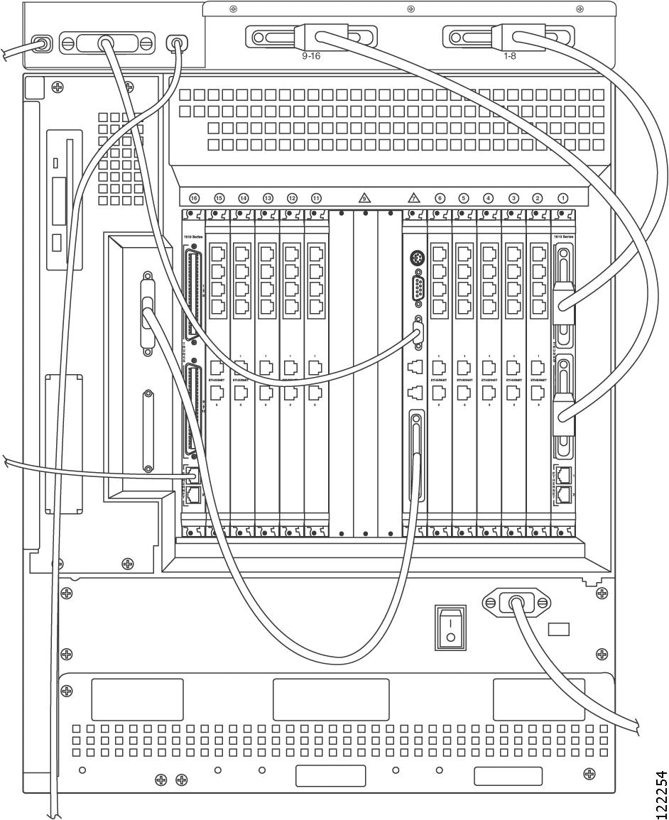
Figure 2-18 shows the connections on the back of a Cisco Unified MeetingPlace 8112. This configuration supports 480 E1 ports with one Multi Access Blade card MP-MA-16-PRI.
Figure 2-18 Back of Cisco Unified MeetingPlace 8112 (E1 with 1 MP-MA-16-PRI)
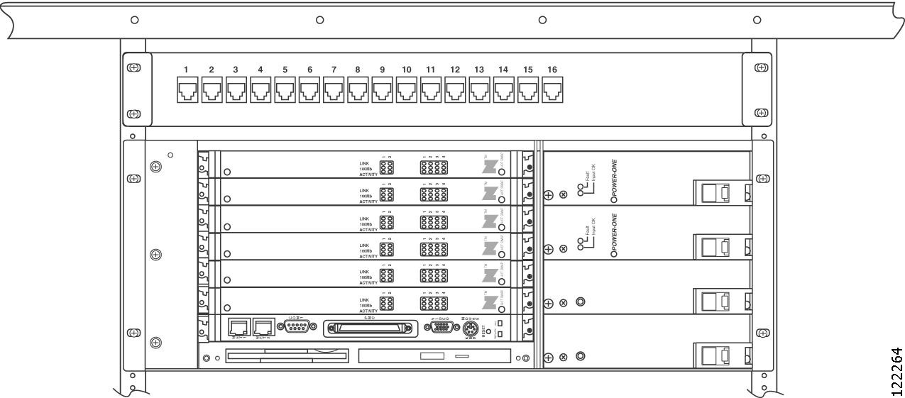
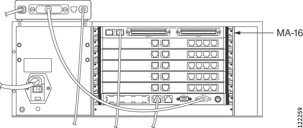
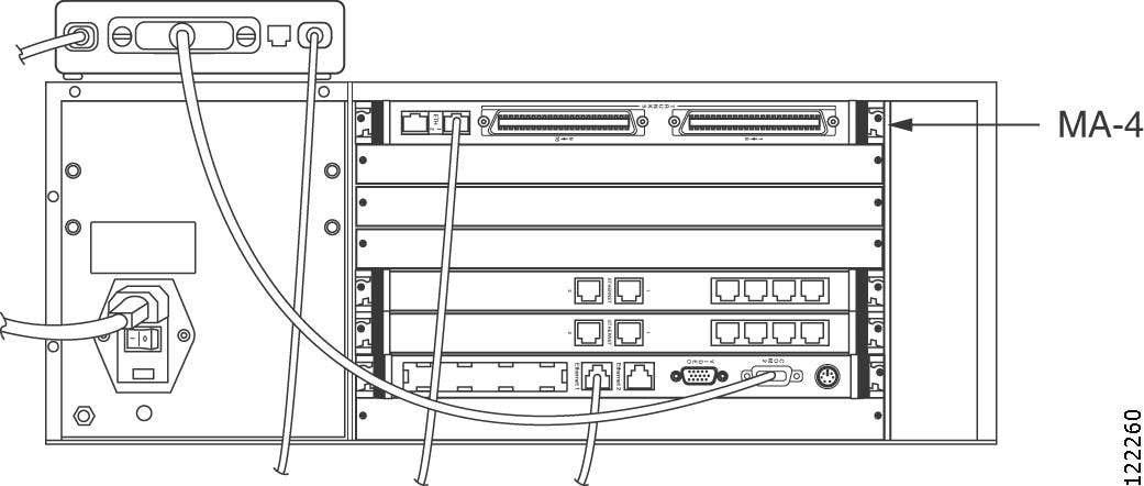
Figure 2-19 shows the connections on the back of a Cisco Unified MeetingPlace 8106. This configuration supports 368 T1 PRI ports with one Multi Access Blade card MP-MA-16-PRI.
Figure 2-19 Back of Cisco Unified MeetingPlace 8106 (T1 PRI with 1 MP-MA-16-PRI)
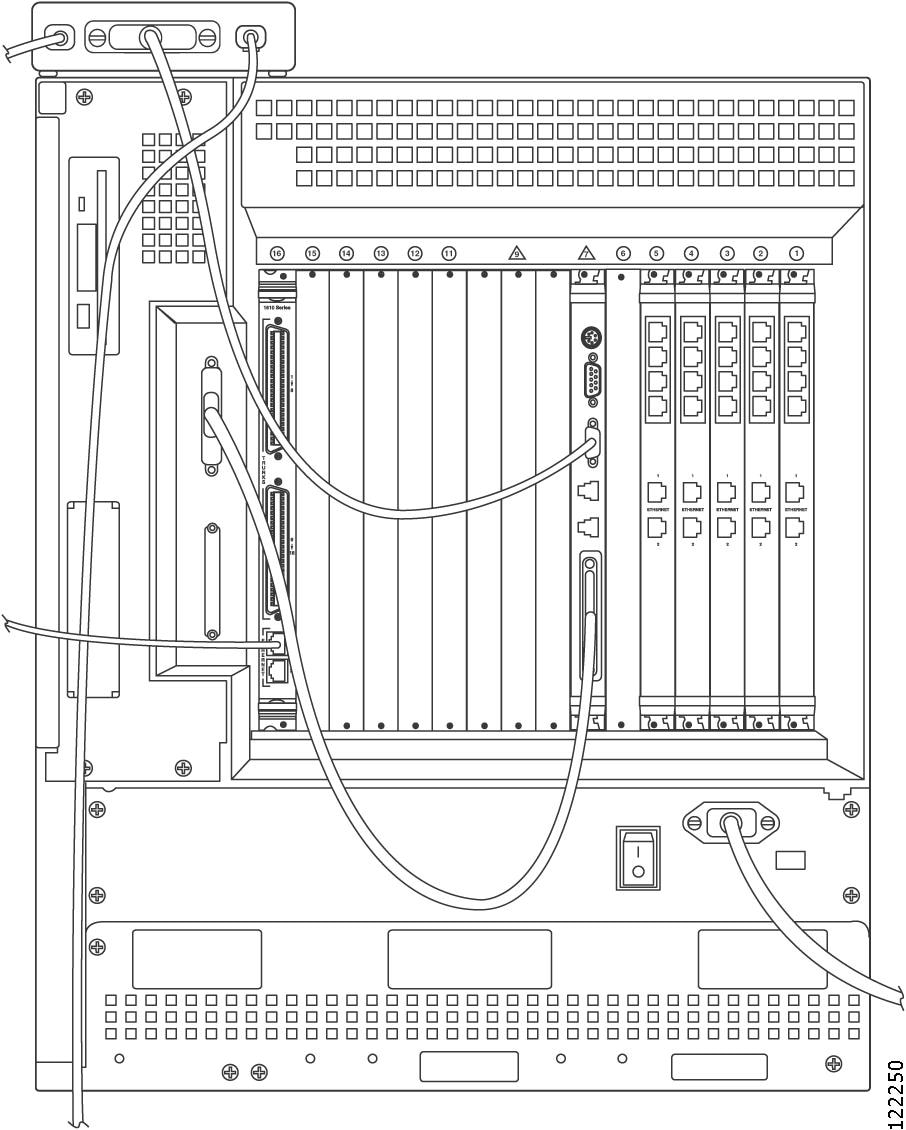
Figure 2-20 shows the connections on the back of a Cisco Unified MeetingPlace 8112. This configuration supports 368 T1 PRI ports with one Multi Access Blade card MP-MA-16-PRI.
Figure 2-20 Back of Cisco Unified MeetingPlace 8112 (T1 PRI with 1 MP-MA-16-PRI)
Connecting E1 or T1 PRI Telephony Cables with One Multi Access Blade MP-MA-4-PRI
To Connect E1 or T1 PRI Telephony Cables with One Multi Access Blade MP-MA-4-PRI
Step 1
•
•
•
Step 2
In many cases, the other equipment has an RJ-48c socket in which to plug the E1 or T1 PRI telephony cable. Alternately, the other equipment will be connected to a punchdown block. In this case, you will need to determine the block's connection diagram and then connect to it with discrete wires from the cable.
Step 3
Step 4
Step 5
Looking at the back of the breakout box, the connector on the right of the breakout box is for spans 1 to 8 and the connector on the left of the breakout box is for spans 9 to 16. Place the trunk card cable assembly into the connector on the right. See Figure 2-14.
Step 6
For the Cisco Unified MeetingPlace 8106, place the 50-pin Amphenol cable into the connector on the left, labeled spans 9 to 16.
For the Cisco Unified MeetingPlace 8112, place the 50-pin Amphenol cable into the connector on the bottom, labeled spans 9 to 16.
Connecting E1 or T1 PRI Telephony Cables with Two Multi Access Blade MP-MA-4-PRIs
To Connect E1 or T1 PRI Telephony Cables with Two Multi Access Blade MP-MA-4-PRIs
Step 1
•
•
•
Step 2
In many cases, the other equipment has an RJ-48c socket in which to plug the E1 or T1 PRI telephony cable. Alternately, the other equipment will be connected to a punchdown block. In this case, you will need to determine the block's connection diagram and then connect to it with discrete wires from the cable.
Step 3
Step 4
Place the second, third, and fourth E1 or T1 PRI telephony cables, which correspond to the first MP-MA-4-PRI, into the RJ-45 jacks labeled 2, 3, and 4. Place the second set of four E1 or T1 PRI telephony cables, which corresponds to the second MP-MA-4-PRI, into the RJ-45 jacks labeled 9, 10, 11, and 12.
Note
Step 5
Looking at the back of the breakout box, place the first trunk card cable assembly into the connector on the right.
Step 6
For the Cisco Unified MeetingPlace 8106, place the 50-pin Amphenol cable into the connector on the left, labeled spans 9 to 16.
For the Cisco Unified MeetingPlace 8112, place the 50-pin Amphenol cable into the connector on the bottom, labeled spans 9 to 16.
Step 7
For the Cisco Unified MeetingPlace 8106, place the 50-pin Amphenol cable into the connector on the left side of the breakout box and on the left of the Multi Access Blade in the connector labeled spans 9 to 16.
For the Cisco Unified MeetingPlace 8112, place the 50-pin Amphenol cable into the connector on the left side of the breakout box and on the bottom of the Multi Access Blade in the connector labeled spans 9 to 16.
Connecting E1 or T1 PRI Telephony Cables with One Multi Access Blade MP-MA-16-PRI and One Multi Access Blade MP-MA-4-PRI
This configuration is supported only on a Cisco Unified MeetingPlace 8112.
To Connect E1 or T1 PRI Telephony Cables with One Multi Access Blade MP-MA-16-PRI and One Multi Access Blade MP-MA-4-PRI
Step 1
•
•
•
Step 2
In many cases, the other equipment has an RJ-48c socket in which to plug the E1 or T1 PRI telephony cable. Alternately, the other equipment will be connected to a punchdown block. In this case, you will need to determine the block's connection diagram and then connect to it with discrete wires from the cable.
Step 3
Step 4
Place the second, third, and fourth E1 or T1 PRI telephony cables, which correspond to the MP-MA-4-PRI, into the RJ-45 jacks labeled 2, 3, and 4. Place the remaining 16 E1 or T1 PRI telephony cables, which correspond to the MP-MA-16-PRI, into the 16 RJ-45 jacks on the front of the second breakout box. Start with the RJ-45 jack on the left and continue to the right.
Note
Step 5
Looking at the back of the first breakout box, place the first trunk card cable assembly into the connector on the right.
Step 6
Place the 50-pin Amphenol cable into the connector on the bottom, labeled spans 9 to 16.
Step 7
Place the first trunk card cable assembly into the connector on the left side of the breakout box and on the top of the Multi Access Blade, in the connector labeled spans 1 to 8. Place the second trunk card cable assembly into the connector on the right side of the breakout box and on the bottom of the Multi Access Blade, in the connector labeled spans 9 to 16.
Connecting E1 or T1 PRI Telephony Cables with Two Multi Access Blade MP-MA-16-PRIs
This configuration is supported only on a Cisco Unified MeetingPlace 8112.
To Connect E1 or T1 PRI Telephony Cables with Two Multi Access Blade MP-MA-16-PRIs
Step 1
•
•
•
Step 2
In many cases, the other equipment has an RJ-48c socket in which to plug theE1 or T1 PRI telephony cable. Alternately, the other equipment will be connected to a punchdown block. In this case, you will need to determine the block's connection diagram and then connect to it with discrete wires from the cable.
Step 3
Step 4
Step 5
Looking at the back of the breakout box, place the first trunk card cable assembly into the connector on the right.
Step 6
Place the trunk card cable assembly into the connector on the bottom, labeled spans 9 to 16.
Step 7
The second trunk card cable assembly should go into the connector on the left side of the breakout box and on the right side of the Multi Access Blade, in the connector labeled spans 9 to 16.
Step 8
About Telephony Configurations for IP Cisco Unified MeetingPlace Systems
Pure IP Cisco Unified MeetingPlace systems are configurations that use only IP functionality and do not use any T1 CAS, T1 PRI, or E1 functionality.
Note
Cisco Systems ships the necessary number of IP LAN cables with the Cisco Unified MeetingPlace Audio Server. The number of IP LAN cables that you receive depends on the number of Multi Access Blades in the Cisco Unified MeetingPlace system. You receive one IP LAN cable for every Multi Access Blade.
Looking at the back of the Cisco Unified MeetingPlace 8106, the Multi Access Blade transition modules for IP configurations begin in slot 6 on the top and move down to the bottom. The Smart Blades begin from the bottom in slot 1. They do not have any cables connected to them.
Looking at the back of the Cisco Unified MeetingPlace 8112, the Multi Access Blade transition modules for IP configurations begin in slot 16 on the left and move to the right. The Smart Blades begin in slot 1 and move to the left. They do not have any cables connected to them.
Connecting IP Telephony Cables for Cisco Unified MeetingPlace Systems
To Connect IP Telephony Cables for a Cisco Unified MeetingPlace System
Step 1
Step 2
Step 3
Step 4
Figure 2-21 shows the connections on the back of the Cisco Unified MeetingPlace 8106. This configuration supports 480 IP ports with one MP-MA-16.
Figure 2-21 Back of Cisco Unified MeetingPlace 8106 (IP with 1 MP-MA-16)
Figure 2-22 shows the connections on the back of a Cisco Unified MeetingPlace 8112. This configuration supports 480 IP ports with one MP-MA-16.
Figure 2-22 Back of Cisco Unified MeetingPlace 8112 (IP with 1 MP-MA-16)
Figure 2-23 shows the connections on the back of a Cisco Unified MeetingPlace 8106. This configuration supports 120 IP ports with one MP-MA-4.
Figure 2-23 Back of Cisco Unified MeetingPlace 8106 (IP with 1 MP-MA-4)
Figure 2-24 shows the connections on the back of a Cisco Unified MeetingPlace 8112. This configuration supports 120 IP ports with one MP-MA-4.
Figure 2-24 Back of Cisco Unified MeetingPlace 8112 (IP with 1 MP-MA-4)
About Telephony Configurations for Mixed Cisco Unified MeetingPlace Systems
A mixed Cisco Unified MeetingPlace system is a Cisco Unified MeetingPlace Audio Server system with both an IP configuration and a T1 CAS, T1 PRI, or E1 configuration.
Mixing protocols is supported only in combination with IP ports:
•
•
•
(For example, a Cisco Unified MeetingPlace system cannot have both T1 and E1 ports configured, but it can have T1—either PRI or CAS—and IP ports, or E1 and IP ports. In addition, a Cisco Unified MeetingPlace system cannot have both T1 CAS and T1 PRI ports configured.)
Cisco Systems ships all Cisco Unified MeetingPlace Audio Server systems with the necessary number of cards and cables for the type of mixed configuration:
For All Mixed Configurations
E1, T1 PRI, and IP configurations all use Multi Access Blades. Cisco Systems ships the necessary number of Multi Access Blades with the Cisco Unified MeetingPlace Audio Server system. The number of telephony cables you receive depends on the number of ports being activated. You receive one telephony cable for every 30 ports in an E1 Cisco Unified MeetingPlace system, and one telephony cable for every 23 ports in a T1 PRI Cisco Unified MeetingPlace system.
For T1 CAS/IP Configurations Only
Cisco Systems ships the necessary number of T1 Smart Blades with the Cisco Unified MeetingPlace Audio Server system. Each T1 Smart Blade transition module in the back of the Cisco Unified MeetingPlace Audio Server has connectors for four trunk lines. The number of telephony cables you receive depends on the number of ports being activated. You receive one telephony cable for every 24 ports in a T1 CAS Cisco Unified MeetingPlace system. No breakout box is needed for this configuration.
For E1/IP and T1 PRI/IP Configurations Only
Cisco Systems ships either one or two breakout boxes and cables, depending on the configuration, with the Cisco Unified MeetingPlace Audio Server system. Cisco Systems also ships the necessary number of trunk card interface cable assemblies (50-pin Amphenol cables) for your configuration. These connect the breakout boxes to the Multi Access Blade transition modules.
For the Non-IP Portion of the Mixed Cisco Unified MeetingPlace System
For the Cisco Unified MeetingPlace 8106, the T1 Smart Blade transition modules begin in slot 1 on the bottom and move up (for T1 CAS/IP configurations). The Multi Access Blade transition modules begin in slot 1 on the bottom and move up (for E1/IP and T1 PRI/IP configurations).
For the Cisco Unified MeetingPlace 8112, the T1 Smart Blade transition modules begin in slot 1 on the right and move to the left (for T1 CAS/IP configurations). The Multi Access Blade transition modules begin in slot 1 on the right and move to the left (for E1/IP and T1 PRI/IP configurations).
For the IP Portion of the Mixed Cisco Unified MeetingPlace System
The Smart Blades begin after the last PSTN blade (either a T1 Smart Blade or Multi Access Blade for E1 or T1 PRI) and do not have any cables connected to them.
For the Cisco Unified MeetingPlace 8106, the Multi Access Blade transition modules begin in slot 6 on the top and move down.
For the Cisco Unified MeetingPlace 8112, the Multi Access Blade transition modules begin in slot 16 on the left and move to the right.
See the applicable section, depending on your configuration:
•
•
Connecting the Telephony Cables for an E1/IP or T1 PRI/IP Cisco Unified MeetingPlace System
To Connect the Telephony Cables for an E1/IP or T1 PRI/IP Cisco Unified MeetingPlace System
Step 1
•
•
•
•
Step 2
Step 3
Step 4
Step 5
•
•
•
•
•
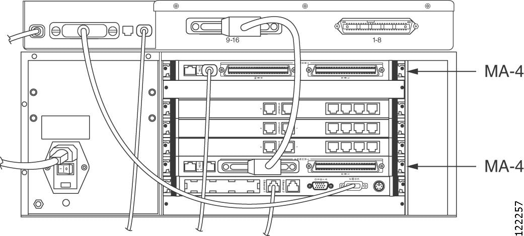
Figure 2-25 shows the connections on the back of a Cisco Unified MeetingPlace 8106 with a mixed Cisco Unified MeetingPlace system. The Multi Access Blade used for the IP configuration is shown at the top, and the Multi Access Blade used for the E1/T1 PRI configuration is shown at the bottom.
Figure 2-25 Back of Cisco Unified MeetingPlace 8106 (Mixed Configuration)
Figure 2-26 shows the connections on the back of a Cisco Unified MeetingPlace 8112 with a mixed Cisco Unified MeetingPlace system with 96 T1 CAS ports and 240 IP ports.
Two MP-MA-4s are used for the IP configuration and are in slots 15 and 16, shown on the left.
For the T1 CAS configuration, there is a T1 Smart Blade in slot 1 and three Smart Blades in slots 2, 3, and 4.
Figure 2-26 Back of Cisco Unified MeetingPlace 8112 (Mixed Configuration with 96 T1 CAS and 240 IP Ports)
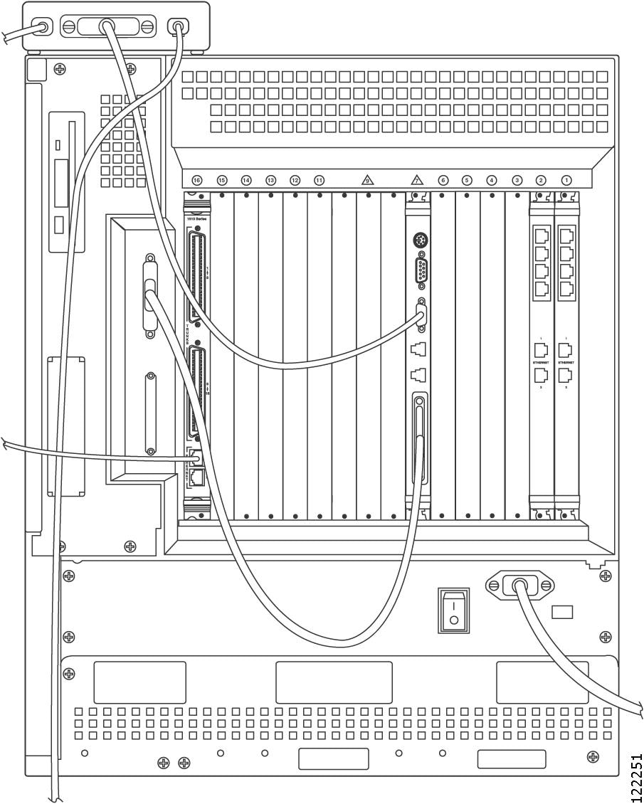
Figure 2-27 shows the connections on the back of a Cisco Unified MeetingPlace 8112 with a mixed Cisco Unified MeetingPlace system with 23 T1 PRI ports and 120 IP ports.
The MP-MA-4 that is used for the IP configuration is shown on the left in slot 16 and the Multi Access Blade MP-MA-4 that is used for the T1 PRI configuration is shown on the right in slot 1.
There is a Smart Blade in slot 2 where 23 ports are used for the T1 PRI configuration, and 73 ports are used for the IP configuration. There is another Smart Blade in slot 3 to support the remaining 47 IP ports.
Figure 2-27 Back of Cisco Unified MeetingPlace 8112 (Mixed Configuration with 23 T1 PRI and 120 IP Ports)
Figure 2-28 shows the connections on the back of a Cisco Unified MeetingPlace 8112 with a mixed Cisco Unified MeetingPlace system with 480 E1 ports and 480 IP ports.
The MP-MA-16 that is used for the IP configuration is shown on the left in slot 16.
The MP-MA-16-PRI that is used for the E1 configuration is shown on the right in slot 1. There are ten Smart Blades (in slots 2, 3, 4, 5, 6, 11, 12, 13, 14, and 15) to support 960 ports.
Figure 2-28 Back of Cisco Unified MeetingPlace 8112 (Mixed Configuration with 480 E1 and 480 IP Ports)
Connecting the Telephony Cables for a T1 CAS/IP Cisco Unified MeetingPlace System
To Connect the Telephony Cables for a T1 CAS/IP Cisco Unified MeetingPlace System
Step 1
•
•
Step 2
In many cases, the other equipment has an RJ-48c socket in which to plug the T1 CAS telephony cable. Alternately, the other equipment will be connected to a punchdown block. In this case, you will need to determine the block's connection diagram and then connect to it with discrete wires from the cable.
Step 3
For the Cisco Unified MeetingPlace 8106, place the first T1 CAS telephony cable in the left most connector slot. Place the second T1 CAS telephony cable in the next connector slot moving to the right, and so on.
For the Cisco Unified MeetingPlace 8112, place the first T1 CAS telephony cable in the topmost connector slot. Place the second T1 CAS telephony cable in the next connector slot moving down, and so on.
You can connect a maximum of four T1 CAS telephony cables to any one T1 Smart Blade transition module.
Step 4
Step 5
Step 6
Step 7
Step 8
Installing and Connecting the Modem
To Install and Connect the Modem
Step 1
•
•
•
•
Step 2
If you have a T1 PRI or an E1 Cisco Unified MeetingPlace system, place the modem into the empty slot on the far left of the breakout box. See Figure 2-14. Do not move the modem from this space.
Step 3
Step 4
Step 5
Step 6
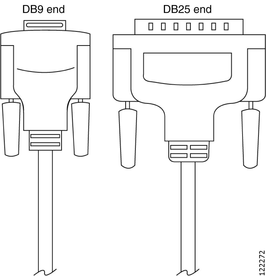
Step 7
Figure 2-29 Modem Cable
Step 8
Step 9
Step 10