-
Installation and Upgrade Guide for Cisco Unified MeetingPlace Audio Server Release 5.4
-
Index
-
Preface
-
Preparing to Install the Cisco Unified MeetingPlace 8100 Series Hardware
-
Installing the Cisco Unified MeetingPlace 8100 Series Hardware
-
Connecting and Setting Up Your Laptop Computer
-
Upgrading the Cisco Unified MeetingPlace Audio Server Software
-
Testing the Cisco Unified MeetingPlace Audio Server System Installation and Upgrade
-
Maintaining the Cisco Unified MeetingPlace Audio Server System
-
Troubleshooting the Cisco Unified MeetingPlace Audio Server System Installation
-
Appendix: Cisco Unified MeetingPlace Audio Server Software Upgrade Reference
-
 Feedback
Table Of Contents
Preparing to Install the Cisco Unified MeetingPlace 8100 Series Hardware
Tools Required for the Installation
Environmental Requirements for the Cisco Unified MeetingPlace 8106
Environmental Requirements for the Cisco Unified MeetingPlace 8112
Power Requirements for the Cisco Unified MeetingPlace 8100 Series
T1 Digital Trunk Requirements for Cisco Unified MeetingPlace Systems
T1-Supported Protocols for Cisco Unified MeetingPlace Systems
Wiring Requirements for Customer-Supplied Connectors—U.S., Canada, and Hong Kong
Wiring Requirements for Customer-Supplied Connectors—U.K., Singapore, and India
E1 Digital Trunk Requirements for Cisco Unified MeetingPlace Systems
E1-Supported Protocols for Cisco Unified MeetingPlace Systems
Modem Requirements for Cisco Unified MeetingPlace Systems
LAN Requirements for Cisco Unified MeetingPlace Systems
LAN Cable Requirements for Cisco Unified MeetingPlace Systems
Preparing to Install the Cisco Unified MeetingPlace 8100 Series Hardware
This chapter describes the requirements and hardware specifications for a Cisco Unified MeetingPlace 8100 series server.
To ensure that the Cisco Unified MeetingPlace configuration integrates within your environment, refer to the configuration worksheets in the Installation Planning Guide for Cisco Unified MeetingPlace Release 5.4 at http://www.cisco.com/en/US/products/sw/ps5664/ps5669/prod_installation_guides_list.html. Complete the pertinent worksheets before proceeding with the installation.
CautionDo not proceed with the installation until you have fulfilled every requirement in this chapter.
This chapter contains the following sections:
•
•
•
•
•
•
•
•
•
•
•
•
•
Safety Warnings
Read the following safety warnings before you begin installing the Cisco Unified MeetingPlace Audio Server system. Translations of the warnings are available online in Regulatory Compliance and Safety Information for Cisco MeetingPlace 8100 Series at http://www.cisco.com/en/US/products/sw/ps5664/ps5669/prod_installation_guides_list.html.
Warning
· This unit should be mounted at the bottom of the rack if it is the only unit in the rack.
· When mounting this unit in a partially filled rack, load the rack from the bottom to the top with the heaviest component at the bottom of the rack.
· If the rack is provided with stabilizing devices, install the stabilizers before mounting or servicing the unit in the rack. Statement 1006
Warning
Warning
Warning
Warning
Warning
Warning
Warning
Warning
Warning
Warning
Warning
Warning
Warning
Warning
Hardware Requirements
The Cisco Unified MeetingPlace Audio Server system requires a Cisco Unified MeetingPlace 8100 series server.
For a new Release 5.4 system, Cisco Unified MeetingPlace Audio Server software is installed in manufacturing, so you do not need to install Audio Server software.
Note
Tools Required for the Installation
Before installing the Cisco Unified MeetingPlace Audio Server, confirm that you have the following tools necessary for a successful installation:
•
•
•
•
•
•
•
•
Figure 1-1 Crossover-Cable Pinouts
Environmental Requirements for the Cisco Unified MeetingPlace 8106
The recommended operating temperature range for the Cisco Unified MeetingPlace 8106 is 50 to 95 degrees Fahrenheit with a noncondensing humidity of 5 to 80 percent.
It is essential to keep the Cisco Unified MeetingPlace 8106 equipment cool. The Cisco Unified MeetingPlace 8106 has an internal fan assembly with four fans. To ensure that all Cisco Unified MeetingPlace 8106 components are adequately cooled, the Cisco Unified MeetingPlace 8106 must meet the following requirements:
•
•
•
•
•
Environmental Requirements for the Cisco Unified MeetingPlace 8112
The recommended operating temperature range for the Cisco Unified MeetingPlace 8112 is 50 to 104 degrees Fahrenheit with a noncondensing humidity of 5 to 80 percent.
It is essential to keep the Cisco Unified MeetingPlace 8112 equipment cool. The Cisco Unified MeetingPlace 8112 has three internal DC-powered fans. To ensure that all Cisco Unified MeetingPlace 8112 components are adequately cooled, the Cisco Unified MeetingPlace 8112 must meet the following requirements:
•
•
•
•
•
Power Requirements for the Cisco Unified MeetingPlace 8100 Series
Power for the Cisco Unified MeetingPlace 8100 series must come from a totally dedicated circuit breaker within 8 feet of the equipment. In addition, the site must have additional power outlets for test and maintenance equipment.
Do not plug any other electrical devices into an outlet connected to the circuit breaker serving the Cisco Unified MeetingPlace 8100 series.
Cisco Unified MeetingPlace 8106 requirements
•
•
•
Cisco Unified MeetingPlace 8112 requirements
•
•
•
If the power in your area is susceptible to fluctuations or interruptions, consider installing surge suppressors or connecting the Cisco Unified MeetingPlace Audio Server system to an uninterruptible power supply (UPS). If the Audio Server system loses power, it does not maintain its telephony connections.
The Cisco Unified MeetingPlace 8106 draws a maximum of 300 watts of power and produces a maximum of 1364 BTU per hour. The Cisco Unified MeetingPlace 8112 draws a maximum of 600 watts of power and produces a maximum of 2048 BTU per hour.
Table 1-1 lists the power requirements by country for the Cisco Unified MeetingPlace 8100 series.
T1 Digital Trunk Requirements for Cisco Unified MeetingPlace Systems
T1 Smart Blades support digital connections to a PBX system or to a public switched phone network (PSTN). The framing for the digital lines can be either Extended Superframe (ESF) or D4 framing. The digital lines can use either Binary 8-Zero Substitution (B8ZS) or jammed-bit coding.
We recommend using ESF framing and B8ZS coding. Using D4 framing or jammed-bit coding may not be satisfactory.
Caution
You must use shielded cables, and you must electrically terminate the shield at the back of the Cisco Unified MeetingPlace Audio Server.
Note the following considerations:
•
•
•
Table 1-2 lists the T1 digital trunk requirements by country for a Cisco Unified MeetingPlace system.
Table 1-2 T1 Digital Trunk Requirements by Country
U.S.
Canada
Hong Kong
Public network to Channel Service Unit (CSU) connection—recEive and transMit (E&M) wink start (line side and trunk side). Ground start or loop start (line side only).
U.S. only—FCC and CSA-listed CSU required.
Customer-supplied connectors—USOC (male) RJ-48 jacks. See the "Wiring Requirements for Customer-Supplied Connectors—U.S., Canada, and Hong Kong" section.
Cable provided by Cisco Systems—25-foot shielded twisted-pair cable with ferrite.
PBX to CSU connection—FCC and CSA-listed CSU required for connections over 600 feet. The Cisco Unified MeetingPlace system ships with a 25-foot shielded cable with ferrite beads for each T1 span. The cable terminates in an RJ-48 connector. Listed CSU is provided for overvoltage protection for the T1 Smart Blades.
Japan
T1 connection into PBX with INS1500-to-T1 converter.
Customer-supplied connectors—RJ-45 connector.
Cable provided by Cisco Systems—50-foot shielded cable (male-male). One per T1 span.
Australia
Cisco Systems does not supply any T1 cables with Cisco Unified MeetingPlace Audio Server systems that are shipped to Australia.
In some cases, the cables that Cisco Systems provides may not be appropriate for your Private Branch eXchange (PBX) or Network Interface Unit (NIU) side connections. If this is the case, create your own custom cables.
Custom T1 CAS (channel-associated signaling) and IP cables require the following:
•
•
Caution
T1-Supported Protocols for Cisco Unified MeetingPlace Systems
The following protocols are supported for T1 digital trunks:
•
•
End-to-end positive disconnect supervision is essential. Without it, Cisco Unified MeetingPlace cannot reliably tell when a caller hangs up. Many PBX and central office systems can provide disconnect signaling; we recommend E&M wink start lines because they provide for a positive answer and disconnect supervision. In many cases, the person taking the order for the lines will not understand your request, so you will probably need to escalate the request to someone with a technical background.
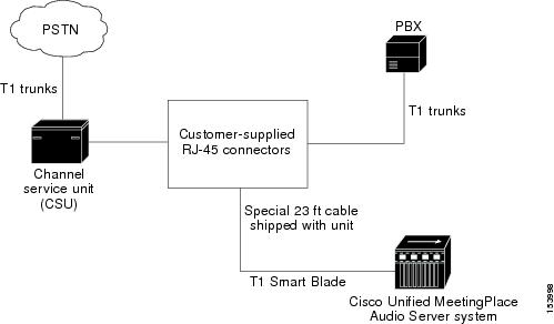
Figure 1-2 illustrates the Cisco Unified MeetingPlace digital telephony connections with T1 trunks.
Figure 1-2 Cisco Unified MeetingPlace Digital Connection Requirements—T1
Wiring Requirements for Customer-Supplied Connectors—U.S., Canada, and Hong Kong
Table 1-3 and Table 1-4 describe wiring requirements for customer-supplied RJ-48 connectors.
To identify the pins, hold the RJ-48 connector as if you are going to plug it in with the tab down. Pin 1 is on the left.
If transmit and receive need to be reversed, also reverse the pins. See Table 1-4.
Wiring Requirements for Customer-Supplied Connectors—U.K., Singapore, and India
For the E1 card, the connection from the network interface to the network can be one of the following types:
•
•
Table 1-5 describes wiring requirements for customer-supplied RJ-45 connectors.
Table 1-5 Wiring of RJ-45 Connectors
1
LRT
Receive +ve (tip)
Input
2
LRR
Receive -ve (ring)
Input
4
LTT
Transmit +ve (tip)
Output
5
LTR
Transmit -ve (ring)
Output
E1 Digital Trunk Requirements for Cisco Unified MeetingPlace Systems
Confirm that the E1 digital trunk specifications meet the requirements in Table 1-6.
In some cases, the RJ-48c cables that Cisco Systems provides may not be appropriate for your PBX or NIU-side connections. If this is the case, create your own custom cables. Custom E1 and T1 PRI cables require the following:
•
•
•
Note
E1-Supported Protocols for Cisco Unified MeetingPlace Systems
The following protocols are supported for E1 digital trunks:
•
•
•
The Cisco Unified MeetingPlace system supports only E1 PRI protocols. The Cisco Unified MeetingPlace system does not support E1 CAS protocols.
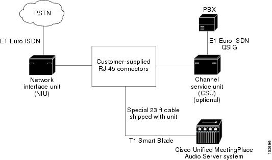
Figure 1-3 illustrates the Cisco Unified MeetingPlace digital telephony connections with E1 trunks.
Figure 1-3 Cisco Unified MeetingPlace Digital Connection Requirements—E1
Modem Requirements for Cisco Unified MeetingPlace Systems
The Cisco Unified MeetingPlace 8100 series includes an external modem that connects to the Cisco Unified MeetingPlace system through a serial cable. Connect the modem cable from the back of the Cisco Unified MeetingPlace 8100 series to the CPU transition module.
Confirm that you can call the modem extension from the outside so that Cisco TAC can access the Cisco Unified MeetingPlace system.
Table 1-7 lists modem requirements by country for a Cisco Unified MeetingPlace system.
LAN Requirements for Cisco Unified MeetingPlace Systems
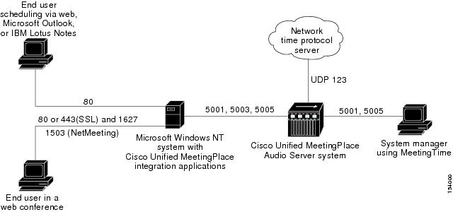
To connect to other applications, such as MeetingTime and Cisco Unified MeetingPlace Web Conferencing, Cisco Unified MeetingPlace Audio Server systems require certain TCP and User Datagram Protocol (UDP) ports to remain open on your network.
Figure 1-4 illustrates the ports that a Cisco Unified MeetingPlace system uses for communication. Unless otherwise specified, all ports listed are TCP.
Figure 1-4 TCP/UDP Port Requirements
Ensure that the Cisco Unified MeetingPlace Audio Server system resides on a network segment that is free from potential network problems, such as storms, loops, and collisions.
LAN Cable Requirements for Cisco Unified MeetingPlace Systems
The Cisco Unified MeetingPlace Audio Server system attaches to an Ethernet LAN, which provides all the communication from the Audio Server system to your network. There are two possible scenarios for using an Ethernet LAN cable:
•
•
For all configurations, you need a customer-supplied LAN cable to connect the Audio Server CPU to your network.
For IP configurations, Cisco Systems supplies the necessary LAN cables to connect the Multi Access Blade that is used for the IP configuration to your network.
Table 1-8 lists the LAN cable requirements by country for a Cisco Unified MeetingPlace system.