-
Cisco Unified Communications SRND Based on Cisco Unified Communications Manager 5.x
-
Preface
-
Introduction
-
IP Telephony Deployment Models
-
Network Infrastructure
-
Gateways
-
Cisco Unified Communications Manager Trunks
-
Media Resources
-
Music on Hold
-
Call Processing
-
Call Admission Control
-
Dial Plan
-
Emergency Services
-
Third-Party Voicemail Design
-
Cisco Unity
-
Cisco Unified MeetingPlace Integration
-
Cisco Unified MeetingPlace Express
-
IP Video Telephony
-
LDAP Directory Integration
-
IP Telephony Migration Options
-
Voice Security
-
IP Telephony Endpoints
-
Cisco Unified Presence
-
Cisco Unified Communications Manager Applications
-
Cisco Mobility Applications
-
Recommended Hardware and Software Combinations
-
Glossary
-
Index
-
Table Of Contents
IP Video Telephony Solution Components
Video Enhancements in Cisco Unified CM 5.x
MTP and Transcoder Support for Video Calls
Media Resource Groups and Lists
Supported Gatekeeper Platforms
Summary of Endpoint Gatekeepers
Migrating from Cisco Unified CM 4.0
Cisco Unified Communications Manager Assistant
Cisco Unified IP Interactive Voice Response and Cisco Unified Contact Center
Cisco IP SoftPhone and Cisco IP Communicator
Cisco Aironet 802.11b Networking Solutions
Cisco Unified Wireless IP Phone 7920
IP Video Telephony
Cisco introduced its IP Video Telephony solution in Cisco Unified Communications Manager (Unified CM, formerly Cisco Unified CallManager) Release 4.0. Video is fully integrated into Unified CM, and there are also many video endpoints available from Cisco and its strategic partners. Cisco Unified Video Advantage is just as easy to deploy, manage, and use as a Cisco Unified IP Phone.
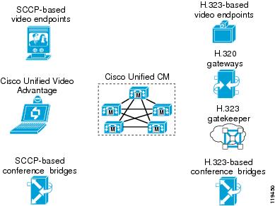
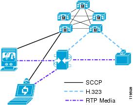
IP Video Telephony Solution Components
The Cisco IP Video Telephony solution consists of Cisco Unified Communications Manager (Unified CM); Cisco Unified Videoconferencing 3500 Series Multipoint Control Units (MCUs) for H.323, Session Initiation Protocol (SIP), and Skinny Client Control Protocol (SCCP) conference calls; Cisco Unified Videoconferencing 3500 Series H.320 Gateways; Cisco IOS H.323 Gatekeeper; Cisco Unified Video Advantage; Cisco IP Video Phone 7985; Sony and Tandberg SCCP endpoint solutions; and the existing range of H.323 or SIP-compliant products from partners such as Polycom, Tandberg, Sony, and others. (See Figure 16-1.)
Figure 16-1 IP Video Telephony Components
Video Enhancements in Cisco Unified CM 5.x
Cisco Unified CM Release 4.0 was the first software release to integrate video capability with IP Telephony. Cisco Unified CM Release 5.x (Release 5.0 and higher) provides additional enhancements in the following areas to support IP Video Telephony:
•
MTP and Transcoder Support for Video Calls
Protocols
Cisco Unified CM Release 5.0 introduced video support for SIP trunks and SIP endpoints. In previous versions of Unified CM, the SIP support was limited to trunking and did not support video.
Unified CM supports a large number of protocols. Any device can call any other device, but video is supported only on SCCP, H.323, and SIP devices. Specifically, video is not supported in the following protocols in Cisco Unified CM Release 5.x:
•
•
Therefore, Unified CM currently supports the types of calls listed in Table 16-1.
Table 16-2 lists the audio and video algorithms and protocols currently supported in Unified CM.
MTP and Transcoder Support for Video Calls
Beginning with Cisco Unified CM Release 5.0, the Cisco IOS Enhanced Media Termination Points (MTPs) support video calls through the use of a pass-through codec. The pass-through codec allows an MTP or transcoder that has been dynamically inserted by Unified CM to terminate the video stream of a video call without having to decode the RTP stream.
Topology-Aware Locations
Beginning with Cisco Unified CM Release 5.0, there are now two methods to limit the amount of bandwidth available for calls between locations. Cisco Unified CM 4.0 introduced support for video calls in locations. More specifically, the location option in Cisco Unified CM 4.0 and 4.1 defines the aggregate bandwidth allowed for all calls between that location and all other locations. This aggregate bandwidth value maps well to traditional hub-and-spoke network topologies. Cisco Unified CM Release 5.x includes a new option to use topology-aware locations based on Resource Reservation Protocol (RSVP) to determine if enough bandwidth is available along the path between two sites. RSVP enables per-hop checking that accommodates complex topologies while supporting the separation of audio bandwidth and video bandwidth via the use of RSVP Application IDs.
Note
RSVP-based locations introduce the concept of an RSVP policy. While there are numerous policy options, there are two main categories:
•
•
First, the audio codec and the video bandwidth set in the region define the maximum speed (bit rate) of the video call. An RSVP reservation is sent from the Cisco RSVP Agent for the audio and video stream of the call using the maximum bit rate as the reservation requirement. If the RSVP reservation for the video stream fails, Unified CM checks the setting of RSVP policy to determine how to handle that call. If the policy for the audio stream is optional, the call will continue as audio-only. Otherwise, if the RSVP policy for the audio stream is mandatory, the call will continue as audio-only unless the audio stream also fails to get an RSVP Reservation. In that case, the call will either fail (with busy tone played and the "Bandwidth Unavailable" message displayed to the user) or Automated Alternate Routing (AAR) will try to reroute the call. (For more details on topology-aware locations, see Call Admission Control.)
Note
Administration Considerations
This section discusses the following configuration elements in Unified CM Administration that pertain to Video Telephony:
Regions
When configuring a region, you set two fields in Unified CM Administration: the Audio Codec and the Video Bandwidth. The audio setting specifies a codec type, while the video setting specifies the amount of bandwidth you want to allow. However, even though the notation is different, the Audio Codec and Video Bandwidth fields actually perform similar functions. The Audio Codec field defines the maximum bit-rate allowed for audio-only calls as well as for the audio channel in video calls. For instance, if you set the Audio Codec for a region to G.711, Unified CM allocates 64 kbps as the maximum bandwidth allowed for the audio channel for that region. In this case, Unified CM will permit calls using either G.711, G.722, G.728, or G.729. However, if you set the Audio Codec to G.729, Unified CM allocates only 8 kbps as the maximum amount of bandwidth allowed for the audio channel, and it will permit calls using only G.729 because G.728, G.711, and G.722 all take more than 8 kbps.
Note
Note
The Video Bandwidth field defines the maximum bit-rate allowed for the video channel of the call. However, for historical continuity with the practices used in traditional videoconferencing products, the value used in this field also includes the bandwidth of the audio channel. For instance, if you want to allow calls at 384 kbps using G.711 audio, you would set the Video Bandwidth field to 384 kbps and not 320 kbps.
In summary, the Audio Codec field defines the maximum bit-rate used for audio-only calls and for the audio channel of video calls, while the Video Bandwidth field defines the maximum bit-rate allowed for video calls and should include the audio portion of the call.
Choosing the correct audio codec bandwidth limit is very important because each device supports only certain audio codecs, as shown in Table 16-3. (For the most recent list of codecs supported by a particular endpoint, refer to the product documentation for that endpoint.)
As Table 16-3 indicates, if you set the region to G.729, not all videoconferencing devices are able to support this type of codec. For example, calls between a Cisco Unified Video Advantage endpoint and a Tandberg endpoint would fail, or Unified CM would allocate an audio transcoding resource for the call.
Cisco Unified CM Release 5.0 introduced audio transcoding resources based on Cisco IOS Enhanced Media Termination Point, which are able to support transcoding the audio stream of a video call while still supporting the video stream via a pass-through codec. The pass-through codec is used only for the video stream because the pass-through codec cannot be used for a stream that requires transcoding. The following three conditions must all be true for the pass-through codec to be used:
•
•
•
Traditional transcoders do not currently support the pass-through capability, so the call would connect as audio-only and would be transcoded between G.729 and G.711. To avoid this situation without using Cisco IOS Enhanced Transcoders, you would have to set the region to use G.711 instead. However, a region set for G.711 would also use G.711 for audio calls between two IP phones, which you might not want due to the increased consumption of bandwidth over the WAN.
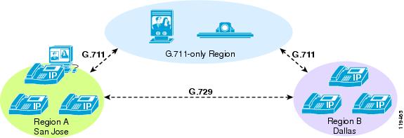
If you want to use G.729 for audio-only calls to conserve bandwidth and to use G.711 for video calls, then you should configure one region to use G.711 for video endpoints that do not support G.729 and a separate region (or regions) to use G.729 for IP phones. (See Figure 16-2.) This method increases the number of regions needed but provides the desired codec and bandwidth allocations.
Figure 16-2 Using G.711 for Video Calls and G.729 for Audio-Only Calls
Note
Table 16-4 lists some example configurations and their outcomes.
The Video Bandwidth field accepts values in the range of 1 to 8128 kbps.However, to allow for compatibility with H.323 and H.320 videoconferencing devices, Cisco recommends that you always enter values for this field in increments of either 56 or 64 kbps. Therefore, valid values for this field include 112 kbps, 128 kbps, 224 kbps, 256 kbps, 336 kbps, 384 kbps, and so forth.
When the call speed requested by the endpoint exceeds the bandwidth value configured for the region, Unified CM automatically negotiates the call down to match the value allowed in the region setting. For instance, assume that an H.323 endpoint calls another H.323 endpoint at 768 kbps, but the region is set to allow a maximum of 384 kbps. The incoming H.225 setup request from the calling party would indicate that the call speed is 768 kbps, but Unified CM would change that value to 384 kbps in the outgoing H.225 setup message to the called party. Thus, the called endpoint would think that it was a 384-kbps call to begin with, and the call would be negotiated at that rate. The calling endpoint would show the requested bandwidth as 768 kbps, but the negotiated bandwidth would be 384 kbps.
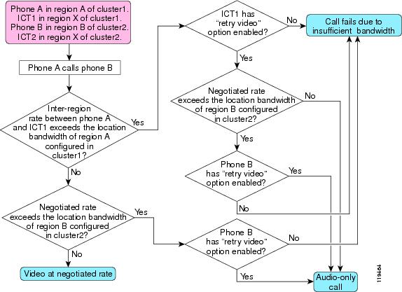
However, if you set the Video Bandwidth to "None" in the region, Unified CM will either terminate the call (and send an H.225 Release Complete message back to the calling party) or will allow the call to pass as an audio-only call instead, depending on whether or not the called device has the Retry Video Call as Audio option enabled. (See Retry Video Call as Audio.)
Locations
When configuring static locations, you also set two fields in Unified CM Administration: the Audio Bandwidth and the Video Bandwidth. Unlike regions however, the Audio Bandwidth for static locations applies only to audio-only calls, while the Video Bandwidth applies to both the audio and video channels of video calls. The audio and video bandwidth are kept separate because, if both types of calls shared a single allocation of bandwidth, then it is very likely that audio calls would take all the available bandwidth and leave no room for any video calls, or vice versa. Also, separate bandwidth pools for audio and video correspond to the way queues are configured in the switches and routers in the network, which typically have a priority queue for voice traffic and a separate priority queue or a Class-Based Weighted Fair Queue for video traffic. (See WAN Quality of Service (QoS), for more details.)
Both the Audio Bandwidth and the Video Bandwidth fields offer three options: None, Unlimited, or a field that accepts numeric values. However, the values entered in these fields use two different calculation models. For the Audio Bandwidth field, the values entered should include the Layers 3 to 7 overhead required for the call. For instance, if you want to permit a single G.729 call to or from a location, you would enter the value of 24 kbps. For a G.711 call, you would enter the value of 80 kbps. The Video Bandwidth field, by contrast, should be entered without the overhead included. For instance, for a 128-kbps call you would enter 128 kbps, and for a 384-kbps call you would enter 384 kbps. As with the values used in the Video Bandwidth field for regions, Cisco recommends that you always use increments of 56 kbps or 64 kbps for the Video Bandwidth field for locations as well.
For example, assume that a company has a three-site network. The San Francisco location has a 1.544-Mbps T1 circuit connecting it to the San Jose main campus. The system administrator wants to allow four G.729 voice calls and one 384-kbps (or two 128-kbps) video calls to/from that location. The Dallas location has two 1.544-Mbps T1 circuits connecting it to the San Jose main campus, and the administrator wants to allow eight G.711 voice calls and two 384-kbps video calls to/from that location. For this example, the administrator would set the San Francisco and Dallas locations to the following values:
When the call speed requested by the endpoint exceeds the value configured for the location, Unified CM will not automatically negotiate the call speed (as it does for regions) to match the value allowed in the location setting. Instead, the call will be rejected or will be retried as an audio-only call (if the Retry Video as Audio setting is enabled on the called device). Therefore, you should always set the region's video bandwidth to a value lower than the location's video bandwidth value. For example, if you have two regions (region A and region B) and you set the video bandwidth between those two regions to 768 kbps but the devices in region A are in a location that has a video bandwidth set to 384 kbps, then all calls between those two regions will fail or will result in audio-only calls (depending on the Retry Video Call as Audio setting).
Retry Video Call as Audio
This check-box is available on all endpoint types that support video, including Cisco Unified IP Phones 7940, 7941, 7960, 7961, 7970, 7971, and Cisco IP Video Phone 7985, as well as Sony or Tandberg SCCP endpoints, and all H.323 and SIP devices (clients, gateways and all types of H.323 trunks). When this option is activated (checked), if there is not enough bandwidth to reach the device (for example, if the Unified CM regions or locations do not allow video for that call), then Unified CM will retry the call as an audio-only call. When this option is deactivated (unchecked), Unified CM will not retry the call as audio-only but instead will either fail the call or reroute the call by whatever automated alternate routing (AAR) path is configured. By default, this retry option is enabled (checked).
This feature applies to the following scenarios only:
•
•
•
The Retry Video Call as Audio option takes effect only on the terminating (called) device, thus allowing the flexibility for the calling device to have different options (retry or AAR) for different destinations.
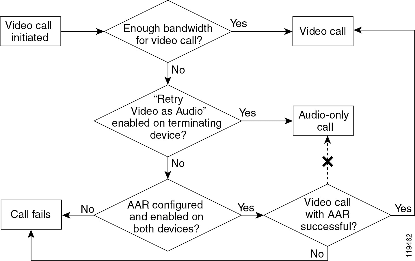
If the video call fails due to bandwidth limitations but automated alternate routing (AAR) is enabled, Unified CM will attempt to reroute the failed call as a video call to the AAR destination. If AAR is not enabled, the failed call will result in a busy tone and an error message being sent to the caller. (See Figure 16-3.) Depending on the type of device that is calling, the failed call will result in one of the following conditions:
•
•
•
Figure 16-3 Possible Scenarios for a Video Call
See the chapter on Call Admission Control, for further details on the use of AAR.
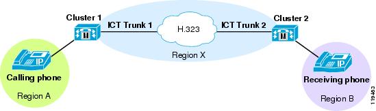
Figure 16-4 illustrates the steps of a call between two clusters using non-gatekeeper controlled intercluster trunks.
Figure 16-4 Call Flow Between Two Clusters Using Non-Gatekeeper Controlled Intercluster Trunks
Wait for Far-End to Send TCS
This check-box is available on all H.323 devices, including H.323 clients, H.323 gateways, and H.225 gatekeeper-controlled trunks This feature pertains to the H.245 capabilities-exchange phase of H.323 calls. When this feature is enabled, Unified CM waits for the remote H.323 device to send its Terminal Capabilities Set (TCS) to Unified CM before Unified CM will send its TCS to the H.323 device. When the option is disabled, Unified CM does not wait but sends its TCS to the remote H.323 device immediately.
By default, the Wait for Far-End to Send TCS option is enabled (checked). However, you must uncheck (disable) it in the following circumstances:
•
In this case, a stalemate occurs because neither side sends its TCS, and the H.245 connection times out after a few seconds. Examples of devices that also wait for the far-end to send TCS are some H.323 routed-mode gatekeepers, H.320 gateways, H.323 proxies (or IP-to-IP gateways) and some H.323 multipoint conference bridges. These devices wait for the far-end to send TCS for the same reason Unified CM does: because they are waiting for both sides of the connection to send their TCSs before forwarding them to the other side.
•
Note
In many scenarios, Unified CM performs the role of a software switch connecting two endpoint devices (such as two H.323 clients that are trying to call each other). In such cases, it is best if Unified CM waits until both devices have sent their TCS messages so that it knows the capabilities of each device and can therefore make the most intelligent decision about what TCS to send back to each party (depending on region and location configurations, among other things). In these cases, the Wait for Far-End to Send TCS feature should be enabled.
However, some other H.323 devices (such as an H.320 gateway, which connects an H.323 device to an H.320 device) also perform the function of connecting two or more parties together. The gateway also prefers to wait until both ends send their TCS messages, so that it can make the most intelligent choice about how to set up the call. A stalemate could result if Unified CM and the gateway both wait for the other side to send their TCSs. To avoid this stalemate situation, disable (uncheck) the Wait for Far-End to Send TCS feature.
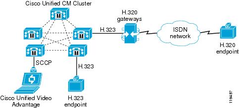
For instance, consider the following call scenarios illustrated in Figure 16-5:
•
•
In both of these scenarios, Wait for Far-End to Send TCS feature can be left at its default setting of enabled (checked)
Figure 16-5 Scenarios with the Wait for Far-End to Send TCS Feature Enabled (Checked)
In Scenario 1 from Figure 16-5, Unified CM already knows the capabilities of the Cisco Unified Video Advantage client because SCCP devices provide Unified CM with their media capabilities during registration. But Unified CM does not know the capabilities of the H.320 gateway until the gateway sends its TCS to Unified CM during the H.245 phase of the call. Likewise, the H.320 gateway does not know what TCS to send to Unified CM until the H.320 endpoint sends its TCS to the gateway. In this case it is better to leave the Wait for Far-End to Send TCS feature enabled because the H.320 endpoint will send its TCS to the gateway, the gateway will send its TCS to Unified CM, and Unified CM will then have the TCSs from both endpoints with which to make a decision.
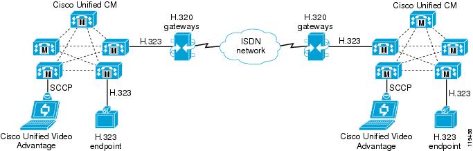
Figure 16-6 shows the following call scenarios, in which the call will fail unless the Wait for Far-End to Send TCS feature is disabled:
•
•
Figure 16-6 Scenarios with the Wait for Far-End to Send TCS Feature Disabled (Unchecked)
In both scenarios from Figure 16-6, there will be a stalemate because both Unified CMs will wait to receive the TCSs from the gateways, and the gateways will both wait to receive the TCS from the ISDN side as well. The call will time-out after a few seconds and fail. From the perspective of the users, the caller will hear ringback tone indicating that the call is progressing and the called party will hear a ring indicating an incoming call. When the called party attempts the answer the call, the H.245 phase will fail due to the stalemate, and the call will then fail by hanging up on both parties.
To work around this issue in scenarios such as these, Cisco recommends that you disable (uncheck) the Wait for Far-End to Send TCS option on the device representing the H.320 gateway in Unified CM. This device could be an H.225 gatekeeper-controlled trunk or an H.323 gateway device, depending on how you have configured Unified CM to reach the H.320 gateway.
However, if the Wait for Far-End to Send TCS option is disabled, there is a possibility that the initial capabilities exchanged will not work for the remote device. For instance, the Unified CM region might be set to 768-kbps video but the H.320 device might only support 384 kbps, or the selected audio codec might not work for the remote party. In such cases, the initially negotiated logical channels might have to be torn down and reopened with the correct speed and codec. Many legacy H.323 and H.320 devices do not handle this situation well and will disconnect the call when Unified CM sends a CloseLogicalChannel message to renegotiate the channel to a different value. Thus, you must be careful where and when you disable the Wait for Far-End to Send TCS option.
Multipoint Conferencing
Whenever three or more parties want to engage in the same video call together, a Multipoint Control Unit (MCU) is required. An MCU consists of the following main components:
•
•
The MC handles all aspects of call setup and teardown for the conference, including media negotiation, call signaling, and choosing which MP to use for the call. The MP processes all the audio and video packets. The MC controls the MP, and one MC can control multiple MPs. The MP can be either software-based or hardware-based. Software-based MPs are typically not capable of advanced transcoding, transrating (multiple speeds), or composition features.
Since 1999, Cisco has offered the Cisco Unified Videoconferencing 3500 Series H.323 Multipoint Conference Units (MCUs). The first product in this family was the Cisco Unified Videoconferencing 3510. This model is no longer available for sale, and is not compatible with Unified CM. In 2002, Cisco introduced the Cisco Unified Videoconferencing 3511 and 3540 models. While these models offer significantly improved features and scalability unavailable on the older 3510 model, the third-generation MCU models (the Cisco Unified Videoconferencing 3515 and 3545) are the recommended platform. The 3515 and 3545 offer an encoder-per-port hardware architecture, which significantly reduces preconfiguration requirements by eliminating the need to limit the bit rates, video formats, and conference features that videoconferencing endpoints and conference participants can use.
In 2003, Cisco introduced software version 3.2+ on the Cisco Unified Videoconferencing 35xx models, which adds support for the Skinny Client Control Protocol (SCCP). SCCP support is not available on the Cisco Unified Videoconferencing 3510. In addition, there are three types of MPs available in the Cisco Unified Videoconferencing MCUs:
•
•
•
Note
Cisco Unified CM Release 4.0 (and later) supports the Cisco Unified Videoconferencing 3511, 3515, 3540, and 3545 models in SCCP, H.323 and SIP modes. Each protocol offers different features and is used for different reasons, so each of these MCUs is equipped to run all three protocols. The Cisco Unified Videoconferencing 3511 can be configured to run in either SCCP mode or H.323 and SIP mode, while the Cisco Unified Videoconferencing 3515, 3540, and 3545 models can be configured to run all three protocols simultaneously and divide the total number of available MP resources between the three.
Regardless of signaling protocol, the MCU provides the same basic function of receiving the audio and video streams from each participant and sending those streams back out to all other participants in some sort of combined view. There are two types of views in a multipoint video conference:
•
•
Voice Activation
Voice-activated conferences take in the audio and video streams of all the participants, decide which participant is the dominant speaker, and send only the dominant speaker's video stream back out to all other participants. The participants then see a full-screen image of the dominant speaker (and the current speaker sees the previous dominant speaker). The audio streams from all participants are mixed together, so everyone hears everyone else, but only the dominant speaker's video is displayed.
You can use any of the following methods to select the dominant speaker:
•
Using this mode, the MCU automatically selects the dominant speaker by determining which conference participant is speaking the loudest and the longest. To determine loudness, the MCU calculates the strength of the voice signal for each participant. As conditions change throughout the conversation, the MCU automatically selects a new dominant speaker and switches the video to display that participant. A hold timer prevents the video from switching too hastily. To become the dominant speaker, a participant has to speak for a specified number of seconds and be more dominant than all other participants.
•
The conference controller (or chairperson) can log onto the MCU's web page, highlight a participant, and select that person as the dominant speaker. This action disables voice activity detection, and the dominant speaker remains constant until the chairperson either selects a new dominant speaker or re-enables voice activation mode.
•
With this method, the MCU stays on each participant for a configured period of time and then switches to the next participant in the list. The conference controller (or chairperson) can turn this feature on and off (re-enable voice activation mode) via the web interface.
Continuous Presence
Continuous-presence conferences display some or all of the participants together in a composite view. The view can display from 2 to 16 squares (participants) in a variety of different layouts. Each layout offers the ability to make one of the squares voice-activated, which is useful if there are more participants in the conference than there are squares to display them all in the composite view. For instance, if you are using a four-way view but there are five participants in the call, only four of them will be displayed at any given time. You can make one of the squares in this case voice-activated so that participants 4 and 5 will switch in and out of that square, depending on who is the dominant speaker. The participants displayed in the other three squares would be fixed, and all of the squares can be manipulated via the conference control web-based user interface.
Note
MP Resources
For both types of conferences, the type of MP resource determines which video formats, transrating, and transcoding capabilities the MCU can support. If endpoints connect to the conference at different speeds, a transrating-capable MP is required. The RM and EMP modules are both capable of transrating between speeds. If a transrating-capable MP is not available, the MCU will send out flow-control messages to all the endpoints, instructing them to lower their transmit speed to match the maximum receive rate of the slowest endpoint. For example, if three participants are connected in a 384-kbps conference and a fourth participant joins at 128 kbps, the MCU will send flow-control messages to the other three participants instructing them to lower their transmit rates to match the 128-kbps participant. This method causes all participants to suffer degraded quality because one participant is less capable. A transrating-capable MP would, instead, convert the 128-kbps stream to 384 kbps, and vice versa, so that each participant can enjoy the best quality their connection allows.
For continuous-presence conferences, a transrating-capable MP is also very important. The software-based MP built into the MCU combines all the input streams and sends the resulting combination back out to each participant. For instance, if four participants are connected in a continuous-presence conference at 384 kbps using G.711 audio, each participant will transmit 320 kbps of video and 64 kbps of audio into the MCU. The MCU will take these four input video streams and combine them into the four-way composite view. The MCU will then transmit 1280 kbps of video back to each endpoint, along with the mixed 64 kbps of audio, for a total of 1344 kbps per endpoint. This method is known as Asynchronous Continuous Presence, and it can have a negative impact on bandwidth requirements, call admission control mechanisms, and interoperability with certain devices.
Note
With the RM or EMP modules, the MCU is capable of transrating each input stream before combining them, so that the total output bandwidth matches the input bandwidth. For instance, if the MCU is using the four-quadrant layout and each participant transmits 320 kbps of video and 64 kbps of audio into the MCU, the MCU would essentially transrate each input stream down to 80 kbps, combine them so that the resulting four-quadrant view is 320 kbps of video (4 * 80 kbps), combine this video with the mixed 64 kbps audio, and transmit the final combination back to each participant. This method is known as Synchronous Continuous Presence. Cisco strongly recommends that all continuous-presence conferences use the Synchronous Continuous Presence mode. However, use of this mode means that each MCU must have a transrating-capable MP (such as an RM or EMP) available, which does increase the cost of the MCU.
Note
SCCP MCU Resources
As stated previously, the Cisco Unified Videoconferencing 3511, 3515, 3540, and 3545 MCUs offer support for SCCP beginning with software version 3.2+ for those models and with Cisco Unified CM Release 4.0. When configured in SCCP mode, Unified CM provides the MC function while the MCU provides the MP function. The SCCP MCU is controlled completely by Unified CM.
Only the following events invoke SCCP MCU resources:
•
•
Participants in either of these types of conferences can include any type of endpoint (that is, video and non-video devices using any signaling protocol that Unified CM supports via any supported gateway type); however, only SCCP endpoints can invoke the SCCP MCU resources. In other words, an H.323 video endpoint cannot invoke an SCCP MCU resource, but an SCCP video endpoint can invoke the resource and then join an H.323 video participant to the call. For example, the user at the SCCP endpoint could press the Conf softkey, dial the directory number of an H.323 client, and then press the Conf softkey again to complete the transaction. The H.323 client will be joined as a participant on the SCCP MCU conference.
However, for ad-hoc conferences initiated via the Conf, Join, or cBarge softkey, the signaling protocol used by the other participants must support the ability to be placed on hold and then have their audio and video channels redirected to the MCU. For H.323 devices (H.323 clients, H.323 gateways, H.320 gateways, and all types of H.323 trunks) Unified CM uses the Empty Capabilities Set (ECS) method defined in the H.245 specification to achieve this functionality. If the H.323 endpoint does not support receiving an ECS message from Unified CM, it will react by hanging up or possibly even crashing and/or rebooting. To work around this problem, you can enable (check) the "MTP Required" option on the H.323 device but assign it a media resource group list (MRGL) that does not contain any MTP devices, and then set the Unified CM service parameter Fail Call if MTP Allocation Fails to False. (For details, see Media Resource Groups and Lists.) This configuration will cause the softkeys to be greyed out on the phone, disabling the user from invoking any supplementary services with that endpoint, including placing it on hold, conferencing it into an existing call, joining it with an existing call, or barging into an existing call containing that endpoint.
Note
For reservationless conferences via the MeetMe softkey, the signaling protocol used by the other endpoints does not have to support being placed on hold and transferred. For these types of conferences, each endpoint dials the MeetMe dial-in number arranged by the SCCP client who initiated the conference.
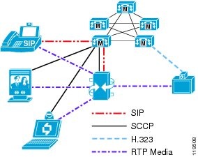
Figure 16-7 illustrates how H.323 and SCCP endpoints can participate in the same SCCP conference. In this example, the conference was initiated by an SCCP endpoint using the Conf softkey to invite the three members.
Figure 16-7 Ad-Hoc Conference Between SCCP and H.323 Endpoints
SCCP conferences support voice-activated mode as well as continuous presence. Furthermore, SCCP conferences support the integrated software-based MP of the MCU and the Rate Matching (RM) module as well as the Enhanced Media Processor (EMP) module.
Media Resource Groups and Lists
Unified CM uses media resource groups (MRGs) and media resource group lists (MRGLs) to determine which specific conference bridge resource to use for a given endpoint. How you group the resources is completely at your discretion, but it is typically done either by geographical placement (so that all endpoints at a given site use the MCU closest to them) or by endpoint type (so that video-capable endpoints use a video-capable MCU while audio-only endpoints use a different conference bridge resource). When a user of an SCCP device activates the Conf, Join, or MeetMe softkey, Unified CM uses the MRGL of the initiating endpoint to determine which conference bridge should be used.
Unified CM applies the following criteria, in the order listed, to select which conference bridge resource to use:
1.
2.
Because of this selection process, the video-capable MCU must be at the top of the MRGL for the video-capable SCCP endpoint in order for that MCU to be selected when the user activates the Conf, Join, or MeetMe softkey on that endpoint. However, some endpoints are not dedicated video endpoints. For example, the IP Phone used in conjunction with Cisco Unified Video Advantage might be used for audio-only calls most of the time and for video calls only occasionally. Thus, if you place the MCU at the top of the MRGL for that phone, the MCU will always be chosen even for audio-only conferences that do not involve any video-capable participants. In this scenario, the MCU resources might be wasted on audio-only conferences and not be available to satisfy the request for a video conference when it occurs.
Therefore, Cisco recommends that you carefully select which users you want to give access to the video-capable MCU resources through MRGLs. The following considerations can help you make that selection:
•
•
•
The answers to these selection criteria will be different for every company. One company might deem multipoint video to be a critical feature and be willing to spend the money necessary to outfit their network with enough MCU resources so that, even if a few ports get wasted on audio-only conferences, there will still be resources available to satisfy all of their video conferences. Another company might choose to enable video resources only for their Sony and Tandberg endpoints and assign audio-only conference bridge resources to Cisco Unified Video Advantage users. A third company might choose to enable video resources for all Sony and Tandberg SCCP endpoints and for select Cisco Unified Video Advantage users (perhaps managers and above), but allocate audio-only resources for the rest of the user population.
H.323 and SIP MCU Resources
When configured in H.323 or SIP mode, the MCU provides the MC function and behaves like an H.323 or SIP peer to Unified CM. H.323 and SIP MCU conferences can be invoked in a number of different ways, but they all fall into two major categories:
•
•
A scheduled conference uses a scheduling application to reserve the MCU resources in advance of the call. The scheduling function typically is provided through a web-based user interface such as Cisco Unified MeetingPlace, MagicSoft VCWizard, RADVision VCS, Tandberg TMS, or FVC.COM Click to Meet. The scheduling application usually generates an invitation that provides the user with the date and time of the conference, the number of ports reserved for the conference, and the dial-in information. Alternatively, the scheduling system can be configured to dial out to some or all of the participants at the beginning of the conference.
For a reservationless conference, the MCU has a certain number of resources that are available on demand. To create a conference, a user simply dials into the MCU at any time. If that user is the first participant to dial in, the MCU dynamically creates a new conference using the settings defined in the service template. (For more information on service templates, see Service Templates and Prefixes.) Subsequent users who dial into the same conference number are joined to that conference.
Any type of endpoint can create and participate in scheduled and reservationless H.323 or SIP conferences. For instance, an SCCP endpoint can dial into the H.323 MCU to create a reservationless conference just as well as an H.323 endpoint can.
Figure 16-8 illustrates how H.323 and SCCP endpoints can participate in the same H.323 conference. In this example, the conference was initiated by an SCCP endpoint that dialed into the H.323 MCU to create a new reservationless conference, and the other two parties subsequently dialed into that conference.
Figure 16-8 SCCP and H.323 Endpoints in a Reservationless Conference
H.323 and SIP conferences support both voice-activated and continuous-presence modes. Furthermore, H.323 conferences support all of the MP types, including the integrated software-based MP of the MCU, the Rate Matching (RM) module, and the Enhanced Media Processor (EMP) module.
Service Templates and Prefixes
A service on the MCU defines the settings that pertain to each conference. You can have different services defined for the different types of conferences. Each service defines, at a minimum, the following settings:
•
This setting might include multiple speeds if a transrating-capable MP is used.
•
The minimum number defines how many ports will be reserved at the beginning of the conference. The maximum number defines the maximum number of participants that the MCU will allow to join this conference.
•
•
•
•
•
A conference can include multiple layouts or even dynamic layouts that change as the number of participants in the conference increases or decreases.
•
When the "SCCP service" check-box is enabled (checked), the service is used for SCCP conferences. When this box is disabled (unchecked), the service is used for H.323 and SIP conferences.
For H.323 and SIP services, each service is assigned a service prefix that is dialed by the endpoints to reach that particular service. The service prefix forms the leading digits of the conference number, and the trailing digits define the conference ID. This format allows multiple conferences to run simultaneously using the same service prefix. For instance, you can have a service prefix of 555, while the full dial string of the conference is seven digits. This scheme would allow for conference numbers in the range of 5550000 through 5559999, with four digits for the conference ID. The user must dial the full string to access the conference. When the call is received by the MCU, the MCU parses the dialed digits to try to match a service prefix. Once it determines which service prefix is being dialed, the MCU then uses the remaining digits as the conference ID. If the conference ID does not exist yet, the MCU creates a new reservationless conference with that ID. If the conference already exists, the user is added to that conference.
It is important to note that, if both H.323 and SIP are enabled on the MCU at the same time, the dial plan must be the same for both protocols. There is no separation between H.323 and SIP as there is with SCCP. If a conference is created using SIP, the MCU will register that conference via H.323. If the gatekeeper or SIP proxy rejects the registration, the conference will fail.
SCCP services must also have a service prefix defined, but the digits themselves do not mean anything because users do not "dial" into an SCCP service. The prefix is used only in the SCCP registration messages between Unified CM and the SCCP MCU resource. Users either use the Conf, Join, or cBarge softkeys to access the SCCP MCU conference (ad hoc), or they dial a MeetMe number assigned by Unified CM to join the conference (reservationless). Therefore, the digits you specify for the SCCP service prefix do not matter and can be any digits you wish, such as 999999 for instance. This prefix is not exposed outside of the SCCP signaling between the MCU and Unified CM (that is, it cannot be dialed, it is not included in the MCU's registration with the gatekeeper, and so forth).
Sizing the MCU
There are several factors involved in determining the types and number of conferences that an MCU can support. These sizing factors are different for different models of MCUs, as described in the following sections.
Cisco Unified Videoconferencing 3515 and 3545
The current MCU models are the Cisco Unified Videoconferencing 3515 and 3545. The Cisco Unified Videoconferencing 3515 MCU supports a fixed number of ports, while the Cisco Unified Videoconferencing 3545 MCU is a modular system that can accept up to three 24-port EMP modules. Unlike previous versions of hardware, all ports of the 3515 and 3545 are fully processed, allowing them to offer any supported connection speed, any supported video and audio codecs, and any supported video resolutions, without any decrease in port capacities or in the number of simultaneous conferences supported. Both MCUs require EMPs to operate; the 3515 has the EMP on-board while the 3545 requires at least one separate module.
Therefore, calculating the size of these MCU is straightforward and depends on the following factors:
•
•
Note
Cisco Unified Videoconferencing 3511 and 3540
The previous MCU models are the Cisco Unified Videoconferencing 3511 and 3540. The Cisco Unified Videoconferencing 3511 MCU supports a fixed number of ports, while the Cisco Unified Videoconferencing 3540 MCU is a modular system that can accept various sizes of modules. When calculating the total number of ports available, you must also consider the number of sessions that the Audio Transcoder Daughter Card and the Rate Matching (RM) module or Enhanced Media Processor (EMP) module can support. Therefore, consider the following factors when calculating the size of these MCUs:
•
This value depends on the speed of the conference; as the speed increases, the number of supported ports decreases.
•
This value depends on which audio codecs are used in the conference.
•
This value depends on how many participants need to be transrated and how many views are in use in the conference.
For specific information about the number of ports supported, refer to the product documentation for your MCU hardware, available on Cisco.com. Due to the almost infinite number of possible variations, it is very difficult to provide any concrete design guidance in this document. Many customers end up with a mixture of SCCP ad-hoc conferences, H.323 and SIP reservationless conferences, and H.323 and SIP scheduled conferences. The MCUs must be sized to accommodate all of those types of conferences at the correct speeds and video layouts. Needless to say, this can become quite complex to determine. Please consult with your Cisco sales representative for assistance on sizing the MCUs for your particular environment.
IVR for Dial-In Conference
Dial-in conferences typically use an interactive voice response (IVR) system to prompt users to enter the conference ID and the password (if one is configured) of the conference they want to join. You can use either of the following types of IVRs with the Cisco Unified Videoconferencing 3500 Series MCUs:
•
•
The built-in IVR of the MCU has the following characteristics:
•
It cannot prompt the user for the conference ID first. In other words, the users must dial the specific conference number they wish to join, then they are prompted for the password of that conference.
•
•
The only thing that can be customized is the recorded audio file that is played to the user.
If you want to have a single dial-in number and then prompt the user for the conference ID, you can use Cisco Unified IP IVR in conjunction with the MCU.
Cisco Unified IP IVR has the following characteristics:
•
•
That is, the calling device must support an out-of-band DTMF method, such as H.245 alpha-numeric on H.323 devices. These out-of-band DTMF messages are then relayed by Unified CM to the Cisco IP IVR server. If the calling device supports only in-band DTMF tones, the Cisco IP IVR server will not recognize them and the calling device will be unable to enter the conference.
•
Customizations can include such things as verifying the user's account against a back-end database before permitting that user to enter into the conference, or queuing the participants until the chairperson joins.
Note
With Cisco Unified IP IVR, users dial a CTI route point that routes the call to the Cisco Unified IP IVR server instead of dialing a route pattern that routes directly to the MCU. After collecting the DTMF digits of the conference ID, the Cisco Unified IP IVR then transfers the call to the route pattern that routes the call to the MCU. This transfer operation requires that the calling device supports having its media channels closed and reopened to a new destination. For example, an H.323 video device that calls the Cisco Unified IP IVR will initially negotiate an audio channel to the Cisco Unified IP IVR server and then, after entering the appropriate DTMF digits, it will be transferred to the MCU, at which point Unified CM will invoke the Empty Capabilities Set (ECS) procedure described earlier in this chapter to close the audio channel between the endpoint and the Cisco Unified IP IVR server and open new logical channels between the endpoint and the MCU. If the H.323 video endpoint does not support receiving an ECS from Unified CM, it will react by disconnecting the call or, worse, crashing and/or rebooting.
Gatekeepers
Prior to the introduction of video support in Unified CM, H.323 videoconferencing networks relied on gatekeepers to perform device registration management, call routing, and bandwidth control. The Cisco IOS Gatekeeper, formerly known as the Multimedia Conference Manager (MCM), provides these functions. However, most gatekeepers, including Cisco's, offer only rudimentary call routing capabilities compared to what might be expected in a typical enterprise-class PBX. When used to route H.323 video calls, Unified CM supplements the basic gatekeeper features and provides full enterprise-class PBX functionality to H.323 video calls.
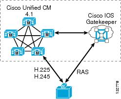
Unified CM and the gatekeeper work as a team to manage H.323 video endpoints. The gatekeeper handles all Registration, Admission, and Status (RAS) signaling, while Unified CM handles all of the H.225 call signaling and H.245 media negotiations. Therefore, you have to deploy gatekeepers along with the Unified CM servers if RAS signaling procedures are required for the H.323 endpoints in your network, as illustrated in Figure 16-9.
Figure 16-9 Unified CM and Cisco IOS Gatekeeper Provide RAS Signaling for H.323 Endpoints
RAS signaling is required any time either of the following conditions exists:
•
If the endpoint uses a static IP address, Unified CM does not require RAS procedures to locate the endpoint. Instead, the endpoint is provisioned in Unified CM Administration with its static IP address, and calls to that H.323 client's directory number are routed directly to that static IP address. If the endpoint does not use a static IP address, then Unified CM must query the gatekeeper to obtain the endpoint's current IP address each time Unified CM extends a call to the endpoint.
•
Most H.323 videoconferencing endpoints are capable of dialing another endpoint directly only when dialing by IP address (that is, the user enters the IP address of the destination endpoint in dotted-decimal format and then pushes the call button). However, if the user dials an E.164-formatted number (a numeric value not in the dotted-decimal format of an IP address) or an H.323-ID (in the format of username or username@domain), most endpoints today provide only one way to resolve these types of destinations - by a RAS query to their gatekeeper. A growing number of endpoints, however, can be configured so that, for any call to an E.164 address, they skip any RAS procedures and instead send an H.225 SETUP message directly to a specified IP address. This method of operation is known as peer-to-peer mode. Tandberg H.323 endpoints are one example that use this mode, in which you can either configure a gatekeeper address for them to register with, or configure the IP address of the Unified CM server they should use. In the latter case, the endpoint sends all calls directly to the specified IP address, bypassing the need for RAS procedures with any gatekeeper.
In addition to managing RAS procedures for H.323 video endpoints, gatekeepers also continue to play an important role in managing dial plan resolution and bandwidth restrictions between Unified CM clusters in large multisite distributed call processing environments. A gatekeeper can also integrate with large numbers of H.323 VoIP gateways within the organization, or it can act as a session border controller between an enterprise IP Telephony network and a service provider VoIP transport network.
Therefore, as it pertains to Cisco IP Video Telephony deployments, the Cisco IOS Gatekeeper can perform one or both of the following roles:
•
An endpoint gatekeeper is configured to manage all RAS procedures for calls to, from, and between H.323 clients, MCUs, and H.320 video gateways. The endpoint gatekeeper directs all such calls to the appropriate Unified CM cluster so that Unified CM can perform all of the H.225 call routing and H.245 media negotiations.
•
An infrastructure gatekeeper is configured to manage all dial plan resolution and bandwidth restrictions (call admission control) between Unified CM clusters, between a Unified CM cluster and a network of H.323 VoIP gateways, or between a Unified CM cluster and a service provider's H.323 VoIP transport network.
In Cisco Unified CM Release 4.0, the endpoint gatekeeper and the infrastructure gatekeeper had to run on separate routers, and each endpoint gatekeeper could service only a single Unified CM cluster. If multiple Unified CM clusters existed within the enterprise, a separate endpoint gatekeeper had to be deployed for each Unified CM cluster. With Cisco Unified CM Release 4.1 or above, it is possible to combine these roles on a single gatekeeper, using it as an endpoint gatekeeper for one or more Unified CM clusters and as the infrastructure gatekeeper for managing calls between clusters or between a cluster and other H.323 VoIP networks. However, for the following reasons (among others), Cisco recommends that you still separate these roles onto two or more gatekeepers:
•
Depending on the Cisco IOS router platform you choose to deploy and your estimated busy hour call volume, you might need several gatekeepers to handle the load.
•
Putting all of your eggs into one basket may not be wise in a large, multi-national VoIP network. Having gatekeepers placed throughout your network (typically by geography) can provide better fault isolation in the event of a gatekeeper failure.
•
Some configuration aspects of the gatekeeper are global in nature (they pertain to all endpoints registered with that gatekeeper). For example, the command arq reject-unknown-prefix, which may be useful in some H.323 VoIP transport environments, conflicts with the use of the gw-type-prefix <prefix> default-technology command, which is used in endpoint gatekeepers to route calls to Unified CM. While Cisco IOS does not stop you from configuring both commands on the same gatekeeper, the arq reject-unknown-prefix command takes precedence and, therefore, calls to unknown numbers will be rejected instead of being routed to Unified CM. In this case, you would have to use one gatekeeper for the H.323 VoIP transport network and another gatekeeper for the Unified CM cluster(s).
Another example of incompatibility can occur in the way you configure the gatekeeper for redundancy. Most Cisco H.323 voice devices, including Cisco Voice Gateways and Unified CM, support the H.323v3 Alternate Gatekeeper feature, which would allow you to configure the gatekeepers as a gatekeeper cluster using the Gatekeeper Update Protocol (GUP) to keep in sync with each other. However, many H.323 video endpoints do not support Alternate Gatekeeper, so the gatekeepers must be configured to use Hot Standby Routing Protocol (HSRP) for redundancy. You cannot mix and match these two redundancy methods on the same gatekeeper. In this case, you might decide to use a gatekeeper cluster for those endpoints that support Alternate Gatekeeper and an HSRP pair of gatekeepers for those that do not.
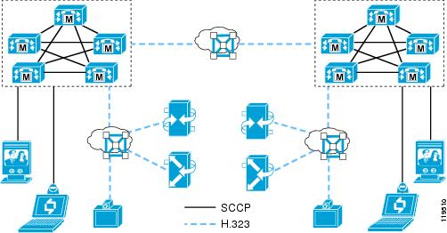
Figure 16-10 illustrates a network scenario with two Unified CM clusters. Each cluster consists of SCCP and H.323 clients, H.323 MCUs, and H.320 gateways. To manage the RAS aspects of the H.323 clients, MCUs, and H.320 gateways, an endpoint gatekeeper is deployed with each cluster. A separate infrastructure gatekeeper manages dial plan resolution and bandwidth between the clusters. Gatekeeper redundancy is not shown in the figure, although each of these gatekeepers may actually be multiple gatekeepers configured for either Alternate Gatekeeper or HSRP-based redundancy.
Figure 16-10 Two Unified CM Clusters with Required Gatekeepers
Supported Gatekeeper Platforms
To act as an endpoint gatekeeper with Cisco Unified CM 4.1 and above, the Cisco IOS Gatekeeper must run Cisco IOS Release 12.3(11)T or greater. For minimum Cisco IOS release requirements on the infrastructure gatekeeper, see Recommended Hardware and Software Combinations.
The following router platforms support the Cisco IOS Gatekeeper:
•
•
•
•
•
•
To determine which release and feature set you should use for your router platform, use the Cisco Feature Navigator (requires a Cisco.com login account), available at
http://tools.cisco.com/ITDIT/CFN/jsp/index.jsp
More information is also available at
That document states that Cisco IOS Release 12.3(11)T provides integrated voice and video services, therefore it is the recommended minimum release.
Endpoint Gatekeepers
An endpoint gatekeeper is required any time both of the following conditions are met:
•
•
–
–
The role of the endpoint gatekeeper is simply to handle the RAS aspects of communications with the endpoints, providing a place for these H.323 endpoints to register. The endpoint gatekeeper responds to all call requests made to, from, or between these endpoints by directing the call to the appropriate Unified CM server(s) so that Unified CM can perform all of the call routing and bandwidth control functions. To accomplish this call routing and bandwidth control, you configure Unified CM to register H.323 trunk(s) with the gatekeeper and configure the gatekeeper to route calls to those trunks for all calls to, from, or within that zone.
Cisco Unified CM Release 4.1 introduced a new type of H.323 trunk called the RASAggregator trunk. This type of trunk is used for all H.323 client, H.323 MCU, or H.320 gateway zones, while the gatekeeper-controlled intercluster trunk and gatekeeper-controlled H.225 trunk from previous Unified CM releases are used to integrate with infrastructure gatekeepers. If you have deployed H.323 video endpoints based on the recommendations documented in the IP Video Telephony SRND for Cisco Unified CallManager 4.0, you should modify your configuration to use the new RASAggregator trunk so that you can take advantage of its flexibility. This configuration change should be carefully planned and done at a time when it is convenient for the administrator so as to minimize disruption to the existing H.323 video endpoints. For a description of the procedure for migrating from a Cisco Unified CM 4.0 deployment, see Migrating from Cisco Unified CM 4.0.
Provisioning H.323 Clients
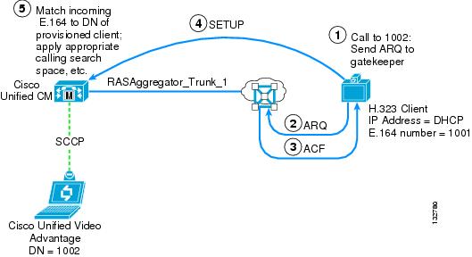
H.323 clients are provisioned much the same way as other phones are, in that you create a new phone (model type = H.323 Client), assign a directory number to it, and assign it a calling search space, device pool, and so forth. You configure the H.323 clients in Unified CM in one of the following ways. The method you use depends on whether or not the client uses a static IP address and whether or not the client requires RAS procedures to dial E.164 addresses.
•
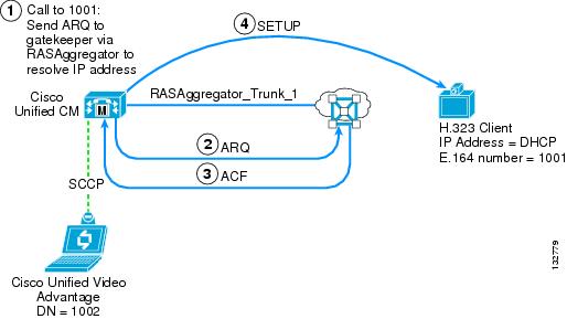
This type of configuration is used for clients that do not have a static IP address assigned to them (they use a DHCP-assigned address) and that require RAS procedures to dial E.164 addresses. A RASAggregator trunk is used to communicate to and from these clients. (See Figure 16-11 and Figure 16-12.)
•
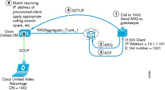
This type of configuration is used for clients that have a static IP address assigned to them but that require RAS procedures to dial E.164 addresses. While Unified CM can signal directly to them without the need of a gatekeeper to resolve their IP addresses, they are not able to signal directly to Unified CM but instead must query the gatekeeper to resolve the E.164 address they are trying to dial (thus, asynchronous communications). To support these types of clients, you must have at least one gatekeeper-controlled client defined in Unified CM for each zone on the gatekeeper, even if all the clients actually use static IP addresses. In this case, the non-gatekeeper controlled client may be a "dummy" client that does not actually exist. It's purpose is merely to create the RASAggregator trunk so that the gatekeeper will be able to route calls from the clients to Unified CM. (See Figure 16-13 and Figure 16-14.)
•
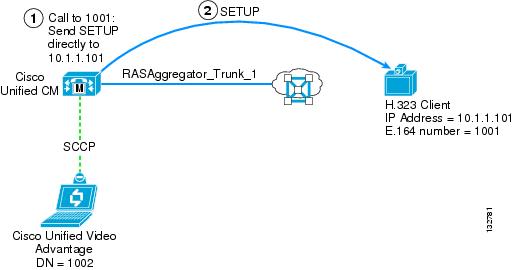
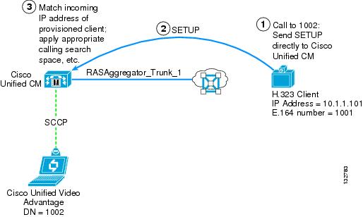
This type of configuration is used for clients that have a static IP address and are also capable of peer-to-peer signaling (that is, they do not require RAS procedures to dial E.164 numbers). Unified CM signals directly to them, and they signal directly to Unified CM (thus, synchronous communications). No gatekeeper or RASAggregator trunk is needed for this type of client. (See Figure 16-15 and Figure 16-16.)
Figure 16-11 through Figure 16-16 illustrate the call signaling flows used in these three scenarios.
Figure 16-11 Call to Gatekeeper-Controlled Client from Unified CM
Figure 16-12 Call from Gatekeeper-Controlled Client to Unified CM
Figure 16-13 Call to Non-Gatekeeper Controlled Client from Unified CM (Asynchronous)
Figure 16-14 Call from Non-Gatekeeper Controlled Client to Unified CM (Asynchronous)
Figure 16-15 Call to Non-Gatekeeper Controlled Client from Unified CM (Synchronous)
Figure 16-16 Call from Non-Gatekeeper Controlled Client to Unified CM (Synchronous)
Gatekeeper-Controlled Clients
When you configure an H.323 client as gatekeeper-controlled, you may enter any alpha-numeric string (such as a descriptive name) in the Device Name field, check the Gatekeeper-controlled box, and fill in the following fields:
•
The device pool you want the client to use. All H.323 clients (whether gatekeeper-controlled or non-gatekeeper controlled) that are registered in the same zone must use the same device pool. If you accidentally assign different device pools across the endpoints, Unified CM will register multiple RASAggregator trunks within the zone, and an inbound call might be rejected by Unified CM if the call is directed to the wrong RASAggregator trunk.
•
A drop-down list of gatekeeper IP addresses. You must define the gatekeeper in Unified CM before configuring any gatekeeper-controlled H.323 clients.
•
The technology prefix used by the RASAggregator trunk to register in the client zone on the gatekeeper. This technology prefix must match what is configured as the default technology prefix on the gatekeeper. All gatekeeper-controlled H.323 clients that are registered in the same zone must use the same technology prefix. If you accidentally assign different technology prefixes across the endpoints, Unified CM will register multiple RASAggregator trunks within the zone, and an inbound call might be rejected by Unified CM if the call is directed to the wrong RASAggregator trunk. Cisco recommends that you use 1# for this prefix.
•
The (case-sensitive) name of the client zone as configured in the gatekeeper. All gatekeeper-controlled H.323 clients that are registered in the same zone must use the same zone name. If you accidentally assign different zone names (remember, the field is case sensitive) across the endpoints, Unified CM will attempt to register multiple RASAggregator trunks with the gatekeeper (but the one with the incorrect zone name will fail to register), and an inbound call might be rejected by Unified CM if the call is directed to the wrong RASAggregator trunk.
Also, you must set the Unified CM service parameter Send Product ID and Version ID to True. This parameter allows the RASAggregator trunk to register with the gatekeeper as an H323-GW, so that the gatekeeper can direct all H.323 calls to, from, or within the client zone to the RASAggregator trunk.
Non-Gatekeeper Controlled Clients
When provisioning an H.323 client as non-gatekeeper controlled, you must enter the static IP address of the client into the Device Name field and leave all of the settings under the Gatekeeper-controlled section blank (unchecked). Unified CM then uses the static IP address to reach the client any time a call is extended to its directory number.
If the client is configured to use peer-to-peer mode, then no further configuration is required. If the client requires RAS procedures to place calls to E.164 addresses, then you must also configure a dummy gatekeeper-controlled H.323 client in order to create the RASAggregator trunk, by filling in the following fields:
•
A descriptive name that identifies this client as a dummy client used for the purpose of creating the RASAggregator trunk for the client zone.
•
The device pool you chose when configuring the non-gatekeeper controlled H.323 client(s). If the device pool assigned to the dummy client is different than that assigned to the real clients, inbound calls from the real clients might be rejected by Unified CM.
•
A drop-down list of gatekeeper IP addresses. You must define the gatekeeper in Unified CM before configuring the dummy gatekeeper-controlled H.323 client.
•
The technology prefix used by the RASAggregator trunk to register in the client zone on the gatekeeper. This technology prefix must match what is configured as the default technology prefix on the gatekeeper. Cisco recommends that you use 1# for this prefix.
•
The (case-sensitive) name of the client zone as configured in the gatekeeper.
Also, you must set the Unified CM service parameter Send Product ID and Version ID to True. This parameter allows the RASAggregator trunk to register with the gatekeeper as an H323-GW, so that the gatekeeper can direct all H.323 calls to, from, or within the client zone to the RASAggregator trunk.
Provisioning H.323 MCUs
H.323 MCUs are provisioned in Unified CM as H.323 gateways, and then route patterns are configured to extend calls to these devices. When provisioning an H.323 gateway, you must enter the static IP address and TCP signaling port of the MCU into the Device Name field. Unified CM then uses the static IP address and TCP port to reach the MCU any time a call matches the route pattern(s) associated with it.
Note
If the MCU is configured to use peer-to-peer mode, then no further configuration is required. (Cisco Unified Videoconferencing MCUs do not currently support peer-to-peer mode, but some third-party MCUs do.) If the MCU requires RAS procedures to place calls to E.164 addresses, then you must also configure a dummy gatekeeper-controlled H.323 client in order to create the RASAggregator trunk, by filling in the following fields:
•
A descriptive name that identifies this client as a dummy client used for the purpose of creating the RASAggregator trunk for the MCU zone.
•
The device pool you chose when configuring the H.323 gateway representing the MCU. If the device pool assigned to the dummy client is different than that assigned to the H.323 gateway device representing the MCU, inbound calls from the MCU might be rejected by Unified CM.
•
A drop-down list of gatekeeper IP addresses. You must define the gatekeeper in Unified CM before configuring the dummy gatekeeper-controlled H.323 client.
•
The technology prefix used by the RASAggregator trunk to register in the MCU zone on the gatekeeper. This technology prefix must match what is configured as the default technology prefix on the gatekeeper. Cisco recommends that you use 1# for this prefix.
•
The (case-sensitive) name of the MCU zone as configured in the gatekeeper.
Also, you must set the Unified CM service parameter Send Product ID and Version ID to True. This parameter allows the RASAggregator trunk to register with the gatekeeper as an H323-GW, so that the gatekeeper can direct all H.323 calls to, from, or within the MCU zone to the RASAggregator trunk.
MCU Service Prefixes
H.323 MCUs can use either E.164 addresses or technology prefixes (also referred to as service prefixes in the MCU) as the dial-in number(s) to reach reservationless or scheduled H.323 conferences running on them. Cisco recommends that you configure the MCUs to use E.164 addresses by setting the MCU Mode to MCU instead of Gateway in the MCU administration screens. If the MCU setting is not available on the model of MCU you are using, then you must use the following special configuration to properly route calls placed from other H.323 endpoints to the MCU:
If the MCU is configured in Gateway mode or is another vendor's MCU that (for whatever reason) requires its conference IDs to register as technology prefixes instead of as E.164 addresses, then the service prefix(s) of the MCU must begin with a # character. For example, if the MCUs service prefix is 8005551212, then you must provision the service prefix on the MCU as #8005551212. Thus, when other H.323 endpoints dial 8005551212, the gatekeeper will not find a matching technology prefix registered and will instead route the call to the RASAggregator trunk that is registered with the default technology prefix in the zone of the endpoint that is placing the call. Unified CM must then prepend the # character to the beginning of the called number before extending the call to the MCU. This character is prepended on the route pattern(s) associated with the H.323 gateway representing the MCU. Calls to the MCU from SCCP clients will therefore also have this # character prepended to the calling number.
If the MCU is configured in MCU mode or is another vendor's MCU that uses E.164 addresses for its conference IDs, then you do not have to prepend the # character. Also note that, if the MCU uses peer-to-peer mode and hence does not need to register its technology prefixes with any gatekeeper, then this situation does not apply and you do not have to prepend a # character.
Provisioning H.320 Gateways
As with H.323 MCUs, H.320 gateways are provisioned in Unified CM as H.323 gateways, and then route patterns are configured to extend calls to these devices. When provisioning an H.323 gateway, you must enter the static IP address and TCP signaling port of the H.320 gateway into the Device Name field. Unified CM then uses the static IP address and TCP port to reach the gateway any time a call matches the route pattern(s) associated with it.
Note
If the gateway is configured to use peer-to-peer mode, then no further configuration is required. If the gateway requires RAS procedures to place calls to E.164 addresses, then you must also configure a dummy gatekeeper-controlled H.323 client in order to create the RASAggregator trunk, by filling in the following fields:
•
A descriptive name that identifies this client as a dummy client used for the purpose of creating the RASAggregator trunk for the gateway zone.
•
The device pool you chose when configuring the H.323 gateway representing the H.320 gateway. If the device pool assigned to the dummy client is different than that assigned to the gateway, inbound calls from the gateway might be rejected by Unified CM.
•
A drop-down list of gatekeeper IP addresses. You must define the gatekeeper in Unified CM before configuring the dummy gatekeeper-controlled H.323 client.
•
This field requires an entry. Ensure that it is "non-dialable" within Unified CM.
•
The technology prefix used by the RASAggregator trunk to register in the gateway zone on the gatekeeper. This technology prefix must match what is configured as the default technology prefix on the gatekeeper. Cisco recommends that you use 1# for this prefix.
•
The (case-sensitive) name of the gateway zone as configured in the gatekeeper.
Also, you must set the Unified CM service parameter Send Product ID and Version ID to True. This parameter allows the RASAggregator trunk to register with the gatekeeper as an H323-GW, so that the gatekeeper can direct all H.323 calls to, from, or within the gateway zone to the RASAggregator trunk.
Gateway Service Prefixes
H.320 gateways use technology prefixes (also referred to as service prefixes in the gateway) as the prefix that users should dial to reach an ISDN destination. For calls to route correctly, you must configure the service prefix(s) of the gateway to begin with a # character. For example, if the gateway's service prefix that clients dial to reach an ISDN number is 9, then you must provision the service prefix on the gateway as #9. In this way, when H.323 clients dial 9 plus the PSTN number (such as 918005551212), the gatekeeper will not find a matching technology prefix registered and will instead route the call to the Unified CM trunk that is registered with the default technology prefix. Unified CM must then prepend the # character to the beginning of the called number before extending the call to the gateway. Note that, if the gateway uses peer-to-peer mode and hence does not need to register its technology prefixes with any gatekeeper, then this situation does not apply and you do not have to prepend a # character.
Gatekeeper Zone Configuration
The preceding sections discuss how to provision the endpoints in Unified CM Administration. You must also configure the endpoint gatekeeper(s) with the appropriate zone definitions. You must configure a zone for each type of endpoint (client, MCU, or gateway) and, optionally, for each device pool associated with these endpoints in Unified CM.
Each zone is configured to route all calls placed to, from, or within the zone to the RASAggregator trunk registered in that zone. You configure the zones on the endpoint gatekeeper by using the following command syntax:
zone local <zone_name> <domain_name> <ip_address> invia <zone_name>
outvia <zone_name> enable-intrazone
The command argument invia applies to calls placed to the zone from any other zone, outvia applies to calls placed from the zone to any other zone, and enable-intrazone applies to calls placed within the zone. The following sections illustrate the use of these commands.
Client Zones
The number of client zones you have to configure within each endpoint gatekeeper depends on the following factors:
•
The device pool determines which Unified CM servers are primary, secondary, and tertiary servers for each H.323 client. If you assign all H.323 clients to the same device pool, then you need to define only a single client zone in the endpoint gatekeeper. In other words, for each device pool used by H.323 clients, you must configure a separate client zone in the gatekeeper.
•
Each client zone is configured to route calls to a particular RASAggregator trunk. Therefore, if one endpoint gatekeeper is used to service multiple Unified CM clusters, then you must define a separate client zone for each cluster that the gatekeeper services.
To illustrate, the following three examples show how client zones may be configured. Example 16-1 shows a single client zone defined for a single Unified CM cluster in which all H.323 clients are associated with the same device pool. Example 16-2 shows a single Unified CM cluster in which the H.323 clients are divided between two different device pools. Example 16-3 shows two Unified CM clusters in which the H.323 clients are divided between two different device pools in each cluster.
Note
Example 16-1 Client Zone for a Single Unified CM Cluster and Single Device Pool
gatekeeperzone local clients domain.com invia clients outvia clients enable-intrazonegw-type-prefix 1# default-technologyno use-proxy clients default inbound-to terminalno use-proxy clients default outbound-from terminal! no arq reject-unknown-prefixendpoint ttl 60no shutdownExample 16-2 Client Zones for a Single Unified CM Cluster and Two Device Pools
gatekeeperzone local dp1-clients domain.com invia dp1-clients outvia dp1-clients enable-intrazonezone local dp2-clients domain.com invia dp2-clients outvia dp2-clients enable-intrazonegw-type-prefix 1# default-technologyno use-proxy dp1-clients default inbound-to terminalno use-proxy dp1-clients default outbound-from terminalno use-proxy dp2-clients default inbound-to terminalno use-proxy dp2-clients default outbound-from terminal! no arq reject-unknown-prefixendpoint ttl 60no shutdownExample 16-3 Client Zones for Two Unified CM Clusters with Two Device Pools per Cluster
gatekeeperzone local clstr1-dp1-clients domain.com invia clstr1-dp1-clients outvia clstr1-dp1-clients enable-intrazonezone local clstr1-dp2-clients domain.com invia clstr1-dp2-clients outvia clstr1-dp2-clients enable-intrazonezone local clstr2-dp1-clients domain.com invia clstr2-dp1-clients outvia clstr2-dp1-clients enable-intrazonezone local clstr2-dp2-clients domain.com invia clstr2-dp2-clients outvia clstr2-dp2-clients enable-intrazonegw-type-prefix 1# default-technologyno use-proxy clstr1-dp1-clients default inbound-to terminalno use-proxy clstr1-dp1-clients default outbound-from terminalno use-proxy clstr1-dp2-clients default inbound-to terminalno use-proxy clstr1-dp2-clients default outbound-from terminalno use-proxy clstr2-dp1-clients default inbound-to terminalno use-proxy clstr2-dp1-clients default outbound-from terminalno use-proxy clstr2-dp2-clients default inbound-to terminalno use-proxy clstr2-dp2-clients default outbound-from terminal! no arq reject-unknown-prefixendpoint ttl 60no shutdownDisabling The Use of Proxy
The Cisco IOS Gatekeeper, formerly known as the Cisco Multimedia Conference Manager (MCM), previously offered an H.323 proxy function that has been at End of Life (EOL) for some time and is not compatible with Unified CM, but the commands in the gatekeeper to use a proxy for all calls to and from terminals (clients) are still enabled by default. You must disable this function for each client zone by using the following command syntax:
gatekeeperno use-proxy <zone_name> default [inbound-to | outbound-from] terminalsThe Cisco MCM proxy was replaced by a new solution called the Cisco IOS Multiservice IP-to-IP Gateway and the associated via-zone-enabled Cisco IOS Gatekeeper. This document does not discuss the IP-to-IP Gateway, but Cisco Unified CM Release 4.1 and above leverages the via-zone and IP-to-IP gateway constructs by registering its RASAggregator trunks with the gatekeeper, effectively mimicking an IP-to-IP gateway so that the gatekeeper will route all invia, outvia, and enable-intrazone calls to the RASAggregator trunk as if it were an IP-to-IP gateway.
Client Zone Prefixes
For H.323 client zones, there is no need to configure zone prefixes or technology prefixes of any kind, except for the default technology prefix. Instead, the invia, outvia, enable-intrazone, and gw-type-prefix <1#> default-technology commands ensure that all calls placed are routed to the RASAggregator trunk associated with the zone in which the call originated.
MCU Zones
The number of MCU zones you have to configure within each endpoint gatekeeper depends on the following factors:
•
The device pool determines which Unified CM servers are primary, secondary, and tertiary servers for each MCU. If you assign all MCUs to the same device pool, then you need to define only a single MCU zone in the endpoint gatekeeper. In other words, for each device pool used by MCUs, you must configure a separate MCU zone in the gatekeeper.
•
Each MCU zone is configured to route calls to a particular RASAggregator trunk. Therefore, if one endpoint gatekeeper is used to service multiple Unified CM clusters, then you must define a separate MCU zone for each cluster that the gatekeeper services.
To illustrate, the following three examples show how MCU zones may be configured. Example 16-4 shows a single MCU zone defined for a single Unified CM cluster in which all MCUs are associated with the same device pool. Example 16-5 shows a single Unified CM cluster in which the MCUs are divided between two different device pools. Example 16-6 shows two Unified CM clusters in which the MCUs are divided between two different device pools.
Note
Example 16-4 MCU Zone for a Single Unified CM Cluster and Single Device Pool
gatekeeperzone local MCUs domain.com invia MCUs outvia MCUs enable-intrazonegw-type-prefix 1# default-technology! no use-proxy MCUs default inbound-to [MCU | gateway]! no use-proxy MCUs default outbound-from [MCU | gateway]! no arq reject-unknown-prefixendpoint ttl 60no shutdownExample 16-5 MCU Zones for a Single Unified CM Cluster and Two Device Pools
gatekeeperzone local dp1-MCUs domain.com invia dp1-MCUs outvia dp1-MCUs enable-intrazonezone local dp2-MCUs domain.com invia dp2-MCUs outvia dp2-MCUs enable-intrazonegw-type-prefix 1# default-technology! no use-proxy dp1-MCUs default inbound-to [MCU | gateway]! no use-proxy dp1-MCUs default outbound-from [MCU | gateway]! no use-proxy dp2-MCUs default inbound-to [MCU | gateway]! no use-proxy dp2-MCUs default outbound-from [MCU | gateway]! no arq reject-unknown-prefixendpoint ttl 60no shutdownExample 16-6 MCU Zones for Two Unified CM Clusters with Two Device Pools per Cluster
gatekeeperzone local clstr1-dp1-MCUs domain.com invia clstr1-dp1-MCUs outvia clstr1-dp1-MCUs enable-intrazonezone local clstr1-dp2-MCUs domain.com invia clstr1-dp2-MCUs outvia clstr1-dp2-MCUs enable-intrazonezone local clstr2-dp1-MCUs domain.com invia clstr2-dp1-MCUs outvia clstr2-dp1-MCUs enable-intrazonezone local clstr2-dp2-MCUs domain.com invia clstr2-dp2-MCUs outvia clstr2-dp2-MCUs enable-intrazonegw-type-prefix 1# default-technology! no use-proxy clstr1-dp1-MCUs default inbound-to [MCU | gateway]! no use-proxy clstr1-dp1-MCUs default outbound-from [MCU | gateway]! no use-proxy clstr1-dp2-MCUs default inbound-to [MCU | gateway]! no use-proxy clstr1-dp2-MCUs default outbound-from [MCU | gateway]! no use-proxy clstr2-dp1-MCUs default inbound-to [MCU | gateway]! no use-proxy clstr2-dp1-MCUs default outbound-from [MCU | gateway]! no use-proxy clstr2-dp2-MCUs default inbound-to [MCU | gateway]! no use-proxy clstr2-dp2-MCUs default outbound-from [MCU | gateway]! no arq reject-unknown-prefixendpoint ttl 60no shutdownDisabling The Use of Proxy
By default, the Cisco IOS Gatekeeper is set to not use a proxy for calls to and from MCUs or gateways. However, if you have enabled the use of proxy for those types of endpoints, you must disable it for each MCU zone by using the following command syntax:
gatekeeperno use-proxy <zone_name> default [inbound-to | outbound-from] [MCU | gateway]If your MCU is registering as an MCU, then use the MCU argument at the end of the no use-proxy command; if your MCU is registering as a gateway, then use the gateway argument instead.
MCU Zone Prefixes
For H.323 MCU zones, there is no need to configure zone prefixes or technology prefixes of any kind, except for the default technology prefix. Instead, the invia, outvia, enable-intrazone, and gw-type-prefix <1#> default-technology commands ensure that all calls placed are routed to the RASAggregator trunk associated with the zone in which the call originated.
If your MCUs are registering their service prefixes as technology prefixes instead of E.164 addresses, use the special configuration described previously for prepending a # character to the MCU's service prefixes (see MCU Service Prefixes). Due to the way the Cisco IOS Gatekeeper selects a via-zone for calls to a technology prefix, when the endpoint dials the service prefix of the MCU, the call will fail if the gatekeeper finds a matching technology prefix registered. You must ensure that the client does not dial the # character, so that the gatekeeper will not find a matching technology prefix and will instead route the call to the RASAggregator trunk associated with the zone in which the call originated.
H.320 Gateway Zones
The number of H.320 gateway zones you have to configure within each endpoint gatekeeper depends on the following factors:
•
The device pool determines which Unified CM servers are primary, secondary, and tertiary servers for each H.320 gateway. If you assign all gateways to the same device pool, then you need to define only a single gateway zone in the endpoint gatekeeper. In other words, for each device pool used by H.320 gateways, you must configure a separate gateway zone in the gatekeeper.
•
Each gateway zone is configured to route calls to a particular RASAggregator trunk. Therefore, if one endpoint gatekeeper is used to service multiple Unified CM clusters, then you must define a separate gateway zone for each cluster that the gatekeeper services.
To illustrate, the following three examples show how gateway zones may be configured. Example 16-7 shows a single gateway zone defined for a single Unified CM cluster in which all H.320 gateways are associated with the same device pool. Example 16-8 shows a single Unified CM cluster in which the gateways are divided between two different device pools. Example 16-9 shows two Unified CM clusters in which the gateways are divided between two different device pools.
Note
Example 16-7 Gateway Zone for a Single Unified CM Cluster and Single Device Pool
gatekeeperzone local gateways domain.com invia gateways outvia gateways enable-intrazonegw-type-prefix 1# default-technology! no use-proxy gateways default inbound-to gateway! no use-proxy gateways default outbound-from gateway! no arq reject-unknown-prefixendpoint ttl 60no shutdownExample 16-8 Gateway Zones for a Single Unified CM Cluster and Two Device Pools
gatekeeperzone local dp1-gateways domain.com invia dp1-gateways outvia dp1-gateways enable-intrazonezone local dp2-gateways domain.com invia dp2-gateways outvia dp2-gateways enable-intrazonegw-type-prefix 1# default-technology! no use-proxy dp1-gateways default inbound-to gateway! no use-proxy dp1-gateways default outbound-from gateway! no use-proxy dp2-gateways default inbound-to gateway! no use-proxy dp2-gateways default outbound-from gateway! no arq reject-unknown-prefixendpoint ttl 60no shutdownExample 16-9 Gateway Zones for Two Unified CM Clusters with Two Device Pools per Cluster
gatekeeperzone local clstr1-dp1-gateways domain.com invia clstr1-dp1-gateways outvia clstr1-dp1-gateways enable-intrazonezone local clstr1-dp2-gateways domain.com invia clstr1-dp2-gateways outvia clstr1-dp2-gateways enable-intrazonezone local clstr2-dp1-gateways domain.com invia clstr2-dp1-gateways outvia clstr2-dp1-gateways enable-intrazonezone local clstr2-dp2-gateways domain.com invia clstr2-dp2-gateways outvia clstr2-dp2-gateways enable-intrazonegw-type-prefix 1# default-technology! no use-proxy clstr1-dp1-gateways default inbound-to gateway! no use-proxy clstr1-dp1-gateways default outbound-from gateway! no use-proxy clstr1-dp2-gateways default inbound-to gateway! no use-proxy clstr1-dp2-gateways default outbound-from gateway! no use-proxy clstr2-dp1-gateways default inbound-to gateway! no use-proxy clstr2-dp1-gateways default outbound-from gateway! no use-proxy clstr2-dp2-gateways default inbound-to gateway! no use-proxy clstr2-dp2-gateways default outbound-from gateway! no arq reject-unknown-prefixendpoint ttl 60no shutdownDisabling The Use of Proxy
By default, the Cisco IOS Gatekeeper is set to not use a proxy for calls to and from gateways. However, if you have enabled the use of proxy for those types of endpoints, you must disable it for each H.320 gateway zone by using the following command syntax:
gatekeeperno use-proxy <zone_name> default [inbound-to | outbound-from] gatewayGateway Zone Prefixes
There is no need to configure zone prefixes of any kind for H.320 gateway zones. Instead, the invia, outvia, enable-intrazone, and gw-type-prefix <1#> default-technology commands ensure that all calls placed are routed to the RASAggregator trunk associated with the zone in which the call originated.
You must also use the special configuration described previously for prepending a # character to the gateway's service prefixes (see Gateway Service Prefixes). Due to the way the Cisco IOS Gatekeeper selects a via-zone for calls to a technology prefix, when the endpoint dials the service prefix of the gateway, the call will fail if the gatekeeper finds a matching technology prefix registered. You must ensure that the client does not dial the # character, so that the gatekeeper will not find a matching technology prefix and will instead route the call to the RASAggregator trunk associated with the zone in which the call originated.
Zone Subnets
As mentioned previously, the H.323 specification permits a single gatekeeper to manage multiple zones. However, the gatekeeper needs a way to decide which zone an endpoint should be placed in when it receives a Registration Request (RRQ) from that device. The RRQ message contains a Gatekeeper Identifier field that enables the endpoint to indicate the zone in which it would like to register. However, many H.323 video endpoints do not populate this field, and if the gatekeeper has multiple zones defined, it will not know which zone to place the endpoint into. Therefore, you must use of the zone subnet command to tell the gatekeeper which zone to associate with the endpoint. This command defines which IP addresses or IP address ranges are permitted to register in each zone. The command syntax requires that you enter a network mask. Therefore, you can specify either a particular host address by entering a 32-bit (/32) network mask or a range of addresses by specifying a smaller network mask.
Because MCUs, H.320 gateways, and Unified CM servers typically use fixed IP addresses but H.323 clients can use DHCP addresses, Cisco recommends that you define zone subnet commands only for the MCU and gateway zones but leave the client zones open so that any IP address is permitted in them. Note that you must also permit the Unified CM servers to register in the MCU and gateway zones, as illustrated in Example 16-10.
Note
Example 16-10 Defining Zone Subnets
gatekeeperno zone subnet MCUs default enablezone subnet MCUs [MCUs_IP_addr]/32 enablezone subnet MCUs [RASAggregators_IP_addr]/32 enableno zone subnet gateways default enablezone subnet gateways [gateways_IP_addr]/32 enablezone subnet gateways [RASAggregators_IP_addr]/32 enable! zone subnet clients default enableno zone subnet clients [MCUs_IP_addr]/32 enableno zone subnet clients [gateways_IP_addr]/32 enableThe configuration in Example 16-10 explicitly permits the MCU and the RASAggregator for the MCU zone to register in the MCU zone, and it explicitly permits the gateway and RASAggregator for the gateway zone to register in the gateway zone. It also explicitly denies the MCU and gateway from registering in the client zone, while implicitly permitting all other IP addresses (including the RASAggregator for the client zone) to register in the client zone.
Endpoint Time to Live
Endpoints send lightweight Registration Requests (RRQs) to their gatekeeper periodically to maintain their registration status. The frequency with which they send these RRQs is referred to as the Time to Live (TTL) value. The endpoint may specify the TTL it wishes to use in the body of its RRQs. The gatekeeper may then honor the endpoint's requested TTL value by echoing it in the Registration Confirm (RCF) response or, alternatively, may override the endpoint's request by specifying a different TTL value in the RCF.
If the TTL value is not specified in the RRQ, the gatekeeper should specify one in its RCF response. The endpoint should then honor the TTL specified by the gatekeeper. The Cisco IOS Gatekeeper honors all TTL values specified by the endpoints. However, many H.323 video endpoints do not specify a TTL value in their RRQs. In such cases, the Cisco IOS Gatekeeper defaults to specifying a TTL value of 1800 seconds (30 minutes). The Cisco IOS Gatekeeper will flush the endpoint's registration after three TTL intervals have passed without receiving any messages from the endpoint (3 * 30 minutes = 90 minutes).
A large TTL value can cause problems with H.323 clients that do not use static IP addresses. For example, with the default TTL value of 1800 seconds, if you disconnect the client from the network and move it to another location in which it receives a different DHCP address, it will fail to register with the gatekeeper (Registration Reject (RRJ) cause value "duplicate alias") until three TTL intervals have passed, and the gatekeeper will flush that endpoint's original registration.
Therefore, Cisco recommends that you consider reducing the TTL value to as low a number as possible without causing any negative effect on your network. The Cisco IOS Gatekeeper permits you to set the TTL value anywhere in the range of 60 seconds to 3600 seconds. In most cases, 60 seconds should work well. However, if your gatekeeper is already heavily utilized, adjusting the TTL from the default of 1800 seconds to 60 seconds might cause it to become overwhelmed.
Use the following command syntax to set the TTL value:
gatekeeperendpoint ttl <seconds>Summary of Endpoint Gatekeepers
This section summarizes some key points to remember about endpoint gatekeepers and provides some example configurations that combine techniques used in the previous examples.
•
•
•
•
•
•
•
Example 16-11 shows a configuration for an endpoint gatekeeper servicing a single Unified CM cluster in which a single device pool is used to service all H.323 video endpoint types.
Note
Example 16-11 Endpoint Gatekeeper Configuration for a Single Cluster and a Single Device Pool
gatekeeperzone local clients domain.com invia clients outvia clients enable-intrazonezone local MCUs domain.com invia MCUs outvia MCUs enable-intrazonezone local gateways domain.com invia gateways outvia gateways enable-intrazone! zone subnet clients default enableno zone subnet clients [MCUs_IP_addr]/32 enableno zone subnet clients [gateways_IP_addr]/32 enableno zone subnet MCUs default enablezone subnet MCUs [MCUs_IP_addr]/32 enablezone subnet MCUs [RASAggregators_IP_addr]/32 enableno zone subnet gateways default enablezone subnet gateways [gateways_IP_addr]/32 enablezone subnet gateways [RASAggregators_IP_addr]/32 enableno use-proxy clients inbound-to terminalsno use-proxy clients outbound-from terminals! no use-proxy MCUs inbound-to [MCU | gateway]! no use-proxy MCUs outbound-from [MCU | gateway]! no use-proxy gateways inbound-to gateway! no use-proxy gateways outbound-from gatewaygw-type-prefix 1# default-technology! no arq reject-unknown-prefixendpoint ttl 60no shutdownExample 16-12 shows a configuration for an endpoint gatekeeper servicing two Unified CM clusters. Each cluster has two different device pools for its H.323 video endpoints.
Example 16-12 Endpoint Gatekeeper Configuration for Two Clusters and a Two Device Pools
gatekeeperzone local clstr1-dp1-clients domain.com invia clstr1-dp1-clients outvia clstr1-dp1-clients enable-intrazonezone local clstr1-dp1-MCUs domain.com invia clstr1-dp1-MCUs outvia clstr1-dp1-MCUs enable-intrazonezone local clstr1-dp1-gateways domain.com invia clstr1-dp1-gateways outvia clstr1-dp1-gateways enable-intrazonezone local clstr1-dp2-clients domain.com invia clstr1-dp2-clients outvia clstr1-dp2-clients enable-intrazonezone local clstr1-dp2-MCUs domain.com invia clstr1-dp2-MCUs outvia clstr1-dp2-MCUs enable-intrazonezone local clstr1-dp2-gateways domain.com invia clstr1-dp2-gateways outvia clstr1-dp2-gateways enable-intrazonezone local clstr2-dp1-clients domain.com invia clstr2-dp1-clients outvia clstr2-dp1-clients enable-intrazonezone local clstr2-dp1-MCUs domain.com invia clstr1-dp2-MCUs outvia clstr2-dp1-MCUs enable-intrazonezone local clstr2-dp1-gateways domain.com invia clstr2-dp1-gateways outvia clstr2-dp1-gateways enable-intrazonezone local clstr2-dp2-clients domain.com invia clstr2-dp2-clients outvia clstr2-dp2-clients enable-intrazonezone local clstr2-dp2-MCUs domain.com invia clstr2-dp2-MCUs outvia clstr2-dp2-MCUs enable-intrazonezone local clstr2-dp2-gateways domain.com invia clstr2-dp2-gateways outvia clstr2-dp2-gateways enable-intrazone! zone subnet clstr1-dp1-clients default enableno zone subnet clstr1-dp1-clients [clstr1-dp1 MCUs_IP_addr]/32 enableno zone subnet clstr1-dp1-clients [clstr1-dp2 MCUs_IP_addr]/32 enableno zone subnet clstr1-dp1-clients [clstr2-dp1 MCUs_IP_addr]/32 enableno zone subnet clstr1-dp1-clients [clstr2-dp2 MCUs_IP_addr]/32 enableno zone subnet clstr1-dp1-clients [clstr1-dp1 gateways_IP_addr]/32 enableno zone subnet clstr1-dp1-clients [clstr1-dp2 gateways_IP_addr]/32 enableno zone subnet clstr1-dp1-clients [clstr2-dp1 gateways_IP_addr]/32 enableno zone subnet clstr1-dp1-clients [clstr2-dp2 gateways_IP_addr]/32 enable! zone subnet clstr1-dp2-clients default enableno zone subnet clstr1-dp2-clients [clstr1-dp1 MCUs_IP_addr]/32 enableno zone subnet clstr1-dp2-clients [clstr1-dp2 MCUs_IP_addr]/32 enableno zone subnet clstr1-dp2-clients [clstr2-dp1 MCUs_IP_addr]/32 enableno zone subnet clstr1-dp2-clients [clstr2-dp2 MCUs_IP_addr]/32 enableno zone subnet clstr1-dp2-clients [clstr1-dp1 gateways_IP_addr]/32 enableno zone subnet clstr1-dp2-clients [clstr1-dp2 gateways_IP_addr]/32 enableno zone subnet clstr1-dp2-clients [clstr2-dp1 gateways_IP_addr]/32 enableno zone subnet clstr1-dp2-clients [clstr2-dp2 gateways_IP_addr]/32 enable! zone subnet clstr2-dp1-clients default enableno zone subnet clstr2-dp1-clients [clstr1-dp1 MCUs_IP_addr]/32 enableno zone subnet clstr2-dp1-clients [clstr1-dp2 MCUs_IP_addr]/32 enableno zone subnet clstr2-dp1-clients [clstr2-dp1 MCUs_IP_addr]/32 enableno zone subnet clstr2-dp1-clients [clstr2-dp2 MCUs_IP_addr]/32 enableno zone subnet clstr2-dp1-clients [clstr1-dp1 gateways_IP_addr]/32 enableno zone subnet clstr2-dp1-clients [clstr1-dp2 gateways_IP_addr]/32 enableno zone subnet clstr2-dp1-clients [clstr2-dp1 gateways_IP_addr]/32 enableno zone subnet clstr2-dp1-clients [clstr2-dp2 gateways_IP_addr]/32 enablezone subnet clstr2-dp2-clients default enableno zone subnet clstr2-dp2-clients [clstr1-dp1 MCUs_IP_addr]/32 enableno zone subnet clstr2-dp2-clients [clstr1-dp2 MCUs_IP_addr]/32 enableno zone subnet clstr2-dp2-clients [clstr2-dp1 MCUs_IP_addr]/32 enableno zone subnet clstr2-dp2-clients [clstr2-dp2 MCUs_IP_addr]/32 enableno zone subnet clstr2-dp2-clients [clstr1-dp1 gateways_IP_addr]/32 enableno zone subnet clstr2-dp2-clients [clstr1-dp2 gateways_IP_addr]/32 enableno zone subnet clstr2-dp2-clients [clstr2-dp1 gateways_IP_addr]/32 enableno zone subnet clstr2-dp2-clients [clstr2-dp2 gateways_IP_addr]/32 enableno zone subnet clstr1-dp1-MCUs default enablezone subnet clstr1-dp1-MCUs [clstr1-dp1 MCUs_IP_addr]/32 enablezone subnet clstr1-dp1-MCUs [clstr1-dp1 RASAggregators_IP_addr]/32 enableno zone subnet clstr1-dp2-MCUs default enablezone subnet clstr1-dp2-MCUs [clstr1-dp2 MCUs_IP_addr]/32 enablezone subnet clstr1-dp2-MCUs [clstr1-dp2 RASAggregators_IP_addr]/32 enableno zone subnet clstr2-dp1-MCUs default enablezone subnet clstr2-dp1-MCUs [clstr2-dp1 MCUs_IP_addr]/32 enablezone subnet clstr2-dp1-MCUs [clstr2-dp1 RASAggregators_IP_addr]/32 enableno zone subnet clstr2-dp2-MCUs default enablezone subnet clstr2-dp2-MCUs [clstr2-dp2 MCUs_IP_addr]/32 enablezone subnet clstr2-dp2-MCUs [clstr2-dp2 RASAggregators_IP_addr]/32 enableno zone subnet clstr1-dp1-gateways default enablezone subnet clstr1-dp1-gateways [clstr1-dp1 gateways_IP_addr]/32 enablezone subnet clstr1-dp1-gateways [clstr1-dp1 RASAggregators_IP_addr]/32 enableno zone subnet clstr1-dp2-gateways default enablezone subnet clstr1-dp2-gateways [clstr1-dp2 gateways_IP_addr]/32 enablezone subnet clstr1-dp2-gateways [clstr1-dp2 RASAggregators_IP_addr]/32 enableno zone subnet clstr2-dp1-gateways default enablezone subnet clstr2-dp1-gateways [clstr2-dp1 gateways_IP_addr]/32 enablezone subnet clstr2-dp1-gateways [clstr2-dp1 RASAggregators_IP_addr]/32 enableno zone subnet clstr2-dp2-gateways default enablezone subnet clstr2-dp2-gateways [clstr2-dp2 gateways_IP_addr]/32 enablezone subnet clstr2-dp2-gateways [clstr2-dp2 RASAggregators_IP_addr]/32 enableno use-proxy clstr1-dp1-clients inbound-to terminalsno use-proxy clstr1-dp1-clients outbound-from terminalsno use-proxy clstr1-dp2-clients inbound-to terminalsno use-proxy clstr1-dp2-clients outbound-from terminalsno use-proxy clstr2-dp1-clients inbound-to terminalsno use-proxy clstr2-dp1-clients outbound-from terminalsno use-proxy clstr2-dp2-clients inbound-to terminalsno use-proxy clstr2-dp2-clients outbound-from terminals! no use-proxy clstr1-dp1-MCUs inbound-to [MCU | gateway]! no use-proxy clstr1-dp1-MCUs outbound-from [MCU | gateway]! no use-proxy clstr1-dp2-MCUs inbound-to [MCU | gateway]! no use-proxy clstr1-dp2-MCUs outbound-from [MCU | gateway]! no use-proxy clstr2-dp1-MCUs inbound-to [MCU | gateway]! no use-proxy clstr2-dp1-MCUs outbound-from [MCU | gateway]! no use-proxy clstr2-dp2-MCUs inbound-to [MCU | gateway]! no use-proxy clstr2-dp2-MCUs outbound-from [MCU | gateway]! no use-proxy clstr1-dp1-gateways inbound-to gateway! no use-proxy clstr1-dp1-gateways outbound-from gateway! no use-proxy clstr1-dp2-gateways inbound-to gateway! no use-proxy clstr1-dp2-gateways outbound-from gateway! no use-proxy clstr2-dp1-gateways inbound-to gateway! no use-proxy clstr2-dp1-gateways outbound-from gateway! no use-proxy clstr2-dp2-gateways inbound-to gateway! no use-proxy clstr2-dp2-gateways outbound-from gatewaygw-type-prefix 1# default-technology! no arq reject-unknown-prefixendpoint ttl 60no shutdownMigrating from Cisco Unified CM 4.0
The process of migrating from the design methodology documented in the Cisco IP Video Telephony SRND for Cisco Unified CallManager 4.0 to the design methodology presented in this chapter consists of the following fundamental steps:
1.
2.
3.
4.
Each of these steps will cause service disruptions to existing H.323 video endpoints, so ensure that these configuration changes are carefully planned and done at a time when the administrator will be able to minimize disruption to the existing H.323 video endpoints.
Applications
Cisco IP Communications provides an expanding portfolio of applications that extend the features of Unified CM and provide advanced capabilities and integration with other communication media. Many of these applications can be used in conjunction with IP Video Telephony devices, even if they do not specifically support video. For instance, Cisco Unified CM Release 4.1 does not support the negotiation of video channels for CTI applications using the TAPI/JTAPI protocols, but that does not necessarily preclude using a CTI application in conjunction with a video call. This section reviews some of the Cisco and third-party applications and discusses whether or not they can be used to provide advanced call treatment for video calls.
CTI Applications
The following applications are based on the Computer Telephony Integration (CTI) interface.
Cisco Emergency Responder
Cisco Emergency Responder (ER) routes emergency (911) calls to the correct Public Safety Answering Point (PSAP). It also provides the PSAP with the correct calling line ID of the originating device so that the PSAP can respond to the correct physical location of the incident and call the party back in the event that the call is disconnected. Cisco ER uses JTAPI to integrate with Unified CM. Emergency calls are routed to Cisco ER via a CTI route point, then Cisco ER decides which PSAP to forward the call to and what calling line ID to display. Cisco ER tracks each endpoint on the network to determine its physical location by using Simple Network Management Protocol (SNMP) and Cisco Discovery Protocol (CDP) to discover the physical port and specific Cisco Catalyst Ethernet switch to which the endpoint is connected. If CDP is not available, Cisco ER can be configured to locate endpoints by their IP subnet instead. Cisco ER then correlates this information with the physical location of the switch and stores the information in its database.
Both Cisco Unified Video Advantage and the Cisco IP Video Phone 7985 support CDP for the purpose of Cisco ER discovery. Cisco Unified Video Advantage does not send CDP messages to the switch directly but relies on its associated Cisco Unified IP Phone for this support. Therefore, if a Video Telephony user dials 911, Cisco ER is able to route the call to the correct PSAP.
Because Sony and Tandberg SCCP endpoints do not support CDP, Cisco ER must track these endpoints by their IP subnet. Cisco ER is therefore able to route the call to the correct PSAP.
Because H.323 videoconferencing clients do not support CDP, Cisco ER must track them by their IP subnet. Cisco ER is therefore able to route the call to the correct PSAP. However, the H.323 device must support the Empty Capabilities Set (ECS) procedure in order to have its call routed by Cisco ER. If the H.323 endpoint does not support receiving an ECS from Unified CM, calls to 911 that are handled by Cisco ER will fail.
Cisco Unified Communications Manager Assistant
Cisco Unified Communications Manager Assistant enables administrative assistants to provide coverage for the managers with whom they are associated. Unified CM Assistant uses JTAPI to integrate with Unified CM. While Unified CM Assistant is not specifically video-capable, there is nothing stopping Unified CM Assistant from being used with phones that are video-enabled. Once Unified CM Assistant has handled the call and the call is transferred to the final destination device, the two devices in the call communicate with each other directly and could establish video channels at that point. For example, if a video-capable endpoint dialed the directory number of a Manager, and the Assistant covered the call using the Unified CM Assistant application, there might not be any video established during the initial handling of the call. But once the Assistant transferred the caller to the Manager, Unified CM could then negotiate video channels. However, H.323 devices must support the Empty Capabilities Set (ECS) procedure in order to interoperate with Unified CM Assistant. If the H.323 endpoint does not support receiving an ECS from Unified CM, calls that are intercepted by Unified CM Assistant will fail when the Assistant attempts to transfer the call to the Manager.
Cisco Unified IP Interactive Voice Response and Cisco Unified Contact Center
Cisco Unified IP Interactive Voice Response (Unified IP IVR) and Cisco Unified Contact Center (Unified CC) use JTAPI to integrate with Unified CM. If a video-capable device calls into an IVR application (such as a help desk), the communication is audio-only while the caller is connected to the application server (that is, while the caller browses the IVR menu or waits in queue for a help-desk member to take the call). However, once the IVR application transfers the call to its final destination, video channels can be negotiated at that time. H.323 devices must support the Empty Capabilities Set (ECS) procedure in order to interoperate with Cisco Unified IP IVR and Unified CC. If the H.323 endpoint does not support receiving an ECS from Unified CM, calls that are intercepted by Cisco Unified IP IVR or Unified CC will fail when the application attempts to transfer the caller to the final destination.
IVR applications often use DTMF tones to select options in the IVR menu. An alternative is speech recognition, which enables the caller to speak commands to the IVR server instead of pressing keys on the phone. Because Cisco Unified IP IVR and Unified CC both use JTAPI to integrate with Unified CM, they pass DTMF tones through out-of-band signaling messages. Many H.323 devices on the market today use in-band DTMF tones, and these H.323 clients would not be able to use DTMF to navigate an IP IVR or Unified CC menu. However, these H.323 clients could use speech recognition if the IVR server is enabled for it. Video-capable devices such as Cisco Unified Video Advantage, Sony or Tandberg SCCP devices, and any H.323 endpoint that uses H.245 alphanumeric out-of-band signaling for DTMF, can navigate the IVR menus using DTMF tones.
Cisco Attendant Console
Cisco Attendant Console uses JTAPI to integrate with Unified CM. The Attendant Console is used as a front-office device to handle incoming calls. Although Attendant Console does not specifically support video, video channels can be negotiated once the call is transferred to its final destination. However, H.323 devices must support the Empty Capabilities Set (ECS) procedure in order to interoperate with the Attendant Console. If the H.323 endpoint does not support receiving an ECS from Unified CM, calls that are intercepted by an Attendant Console will fail when the attendant attempts to transfer the caller to the final destination.
Cisco Personal Assistant
Cisco Personal Assistant (PA) provides two main functions:
•
•
For both of these functions, no video is established while the call is connected to the PA server, but video channels can be negotiated once PA transfers the call to its final destination. H.323 devices must support the Empty Capabilities Set (ECS) procedure in order to interoperate with PA. If the H.323 endpoint does not support receiving an ECS from Unified CM, calls that are intercepted by PA will fail when the application attempts to transfer the caller to the final destination.
Cisco IP SoftPhone and Cisco IP Communicator
Cisco IP SoftPhone uses TAPI to integrate with Unified CM and can be configured either as a standalone softphone or as a software interface to control an associated SCCP hardware phone. Cisco IP SoftPhone does not specifically support video, but it can be used in conjunction with an IP Phone that has a Cisco Unified Video Advantage client associated to it. Cisco IP SoftPhone cannot be used to control a Sony or Tandberg SCCP device.
Cisco IP Communicator differs from IP SoftPhone in that it is an SCCP client and therefore acts like a Cisco 7970 Series IP Phone.
As of version 2.0, Cisco IP Communicator can associate to Cisco Unified Video Advantage 2.0 when both applications reside on the same PC. For more information, refer to the chapter on IP Telephony Endpoints.
Collaboration Solutions
The following technologies are sometimes used to provide video communications between endpoints.
T.120 Application Sharing
Some videoconferencing endpoints use the T.120 protocol to share documents, whiteboards, and text among participants in a conference. Unified CM does not support negotiating a T.120 channel. Instead of T.120, Cisco recommends using web-based collaboration solutions such as Cisco MeetingPlace or other third-party collaboration solutions such as Placeware, Web-Ex, or IBM E-Collaborate.
Cisco Unified MeetingPlace
Cisco Unified MeetingPlace combines a high-end audio and video conferencing solution with a web-based front end for scheduling and participating in conferences. For more information, refer to the chapter on Cisco Unified MeetingPlace Integration, page 14-1.
Wireless Networking Solutions
Because video is so bandwidth intensive, Cisco does not recommend using a shared wireless medium such as 802.11b/g for video endpoints.
Cisco Aironet 802.11b Networking Solutions
The Tandberg T-1000 model endpoint offers a PCMCIA interface in which you can install a Cisco Aironet PCMCIA 802.11b Wireless Adapter. However, you should take care to ensure that the video endpoints do not share the wireless bandwidth with any production IP Phones because video will consume much of the bandwidth and make it difficult to support video, audio, and data all on the same wireless medium.
Cisco Unified Video Advantage relies on a physical Ethernet connection to the physical IP Phone with which it is associated. It is not uncommon for a user to have both a physical Ethernet interface and an Aironet 802.11b Wireless Adapter installed in the same PC. This configuration could cause problems for Cisco Unified Video Advantage if the wireless interface happens to be the preferred path to the network because Cisco Unified Video Advantage will not associate over that interface. Cisco recommends that you always make the physical Ethernet interface the preferred path. Also, when users connect to the PC port on the back of the IP Phone, instruct them to disable their Aironet Adapter to keep it from accidentally taking precedence.
Cisco Unified Wireless IP Phone 7920
The Cisco Unified Wireless IP Phone 7920 does not support video. Nothing prevents a video endpoint from calling a Cisco Unified Wireless IP Phone 7920; however, it will negotiate as an audio-only call. The Wireless IP Phone user can then put the call on hold, transfer it, or conference it. If the caller is an H.323 video endpoint, it must support the Empty Capabilities Set (ECS) procedure in order for these supplementary services to work.
XML Services
Currently there are no XML applications specifically written for the Cisco Unified Video Advantage client solution, Cisco IP Video Phone 7985, or the Sony or Tandberg SCCP endpoints. However, with the exception of the Sony endpoints, these endpoints do support XML applications. Cisco Unified Video Advantage uses a Cisco Unified IP Phone, so any XML application supported on those phone models should also work with Unified Video Advantage.
The Tandberg SCCP endpoints support XML, but not all XML applications currently work on the Tandberg endpoints. For example, Cisco Extension Mobility and the Berbee InformaCast product are two popular XML applications that currently do not work on the Sony or Tandberg SCCP endpoints. Support for these applications will require firmware upgrades to the endpoints as well as changes in Unified CM Administration in some cases.