-
Cisco Unified Communications SRND Based on Cisco Unified Communications Manager 5.x
-
Preface
-
Introduction
-
IP Telephony Deployment Models
-
Network Infrastructure
-
Gateways
-
Cisco Unified Communications Manager Trunks
-
Media Resources
-
Music on Hold
-
Call Processing
-
Call Admission Control
-
Dial Plan
-
Emergency Services
-
Third-Party Voicemail Design
-
Cisco Unity
-
Cisco Unified MeetingPlace Integration
-
Cisco Unified MeetingPlace Express
-
IP Video Telephony
-
LDAP Directory Integration
-
IP Telephony Migration Options
-
Voice Security
-
IP Telephony Endpoints
-
Cisco Unified Presence
-
Cisco Unified Communications Manager Applications
-
Cisco Mobility Applications
-
Recommended Hardware and Software Combinations
-
Glossary
-
Index
-
Table Of Contents
Traffic Patterns and Gateway Sizing
Normal Business Traffic Profile
Contact Center Traffic Profile
Gateway Sizing for Contact Center Traffic
Voice Activity Detection (VAD)
Cisco Access Digital Trunk Gateways
Gateway Protocols and Core Feature Requirements
Site-Specific Gateway Requirements
Gateway Support for Fax Pass-Through and Fax Relay
Gateway Support for Modem Pass-Through and Modem Relay
Supported Platforms and Features
Gateway Combinations and Interoperability of Features
Feature Support Between Similar Gateways
Gateway Configuration Examples
Cisco IOS Gateway Configuration
Unified CM Configuration for Cisco IOS Gateways
Clock Sourcing for Fax and Modem Pass-Through
Loose Gateway Controlled with Named Service Event (NSE)
Gateway Controlled with Capability Exchange Through H.245 or Session Description Protocol (SDP)
Call-Agent-Controlled T.38 with H.323 Annex D
Routing Inbound Calls from the PSTN
Routing Outbound Calls to the PSTN
Automated Alternate Routing (AAR)
ISDN B-Channel Binding, Rollover, and Busy Out
Configuring the Gateways in Unified CM
Voice Gateways Bearer Capabilities
Gateways
Gateways provide a number of methods for connecting an IP telephony network to the Public Switched Telephone Network (PSTN), a legacy PBX, or key systems. Gateways range from specialized, entry-level and stand-alone voice gateways to high-end, feature-rich integrated router and Cisco Catalyst gateways.
This chapter explains important factors to consider when selecting a Cisco gateway to provide the appropriate protocol and feature support for your IP Telephony network. The main topics discussed in this chapter include:
•
Traffic Patterns and Gateway Sizing
Traffic Patterns and Gateway Sizing
This section presents a high-level discussion of the differences between various traffic models or patterns and how they can affect voice gateway selection. The emphasis is on traffic patterns and gateway sizing for traffic-intensive deployments.
Definitions and Terminology
This section uses the following terms and definitions:
•
The number of calls that are all active in the system at the same time.
•
The maximum number of simultaneous calls in active (talk) state that the system can handle. The number of calls expected to be active simultaneously during the busy hour of the day should not exceed this number.
•
The call arrival rate, described as the number of calls that arrive (that is, new call setup attempts) in one second. Call arrival rates are also often quoted in calls per hour, but this metric is looser in the sense that 100 calls arriving in the last five seconds of an hour provides an average call arrival rate of 100 calls per hour (which is an extremely low rate for a communications system), while it also provides an arrival rate of 20 calls per second (which is a high rate). Sustaining 20 calls per second for an entire hour would result in 72,000 calls per hour. Therefore calls-per-hour is not a very useful metric for ascertaining a system's ability to handle bursty call arrival traffic patterns.
•
The number of calls attempted during the busiest hour of the day (the peak hour). This is the same as the calls-per-second rating for the busiest hour of the day, but it is expressed over a period of an hour rather than a second. For example, 10 cps would be equal to 3600 calls per hour. There is also a metric for Busy Hour Call Completions (BHCC), which can be lower than the BHCA (call attempts) under the assumption that not all calls are successful (as when a blocking factor exists). This chapter assumes 100% call completions, so that BHCA = BHCC.
•
Steady arrival means the call attempts are spaced more or less equally over a period of time. For example, 60 calls per hour at a steady arrival rate would present one call attempt roughly every minute (or approximately 0.02 cps). With bursty arrival, the calls arriving over a given period of time (such as an hour) are not spaced equally but are clumped together in one or more spikes. In the worst case, an arrival rate of 60 calls per hour could offer all 60 calls in a single second of the hour, thus averaging 0 cps for most of the hour with a peak of 60 cps for that one second. This kind of traffic is extremely stressful to communications systems.
•
This is the period of "talk time" on a voice call; that is, the period of time between call setup and call teardown when there is an open speech path between the two parties. A hold time of 3 minutes (180 seconds) is an industry average used for traffic engineering of voice systems. The shorter the hold time on the average call, the greater the percentage of system CPU time spent on setting up and tearing down calls compared to the CPU time spent on maintaining the speech path.
PSTN Traffic Patterns
Traffic, when used in the context of voice communication systems, refers to the volume of calls being sent and/or received. Of particular importance is the traffic carried by external circuits such as the public switched telephone network (PSTN). Traffic is measured in Erlangs, and an Erlang is defined as one call lasting for one hour. This section does not go into any further detail on Erlangs other than to say that there are mathematical tables (Erlang-B and Erlang-C) that are used to calculate how many circuits are required for a given amount of offered traffic.
The amount of traffic received and generated by your business determines the size of the external circuits required. However; many customers typically continue to use the same number of circuits for their IP-based communications system as they previously used for a TDM-based system. While this sizing method might work if no issues are encountered, the process of ongoing system traffic analysis should be part of any routine maintenance practices. Traffic analysis can show that the system is over-provisioned for the current levels of traffic (and, therefore, the customer is paying for circuits that are not needed) or, conversely, that the system is under-provisioned and may be suffering from occasional blocked and/or lost calls, in which case increasing the number of circuits will remedy the situation.
Normal Business Traffic Profile
Most customers have a normal traffic profile, which means that they typically have two busy hours per day, one occurring during the morning from 10:00 to 11:00 and the other in the afternoon from 14:00 to 15:00. These busy-hour patterns can often be attributed to such things as employees starting the work day or returning from a lunch break. The calls themselves tend to have longer hold times and they tend to arrive and leave in a steady manner. A generally accepted industry average holding time to use for traffic calculations is 3 minutes.
Assuming that the communications system is engineered with the busy-hour traffic in mind, no issues should arise. Engineering a system below these levels will result in blocked and/or lost calls, which can have a detrimental effect on business.
Contact Center Traffic Profile
Contact centers present somewhat different patterns of traffic in that these systems typically handle large volumes of calls for the given number of agents or interactive voice response (IVR) systems available to service them. Contact centers want to get the most out of their resources, therefore their agents, trunks, and IVR systems are kept busy all the while they are in operation, which usually is 24 hours a day. Call queuing is typical (when incoming call traffic exceeds agent capacity, calls wait in queue for the next available agent), and the agents are usually dedicated during their work shifts to taking contact center calls.
Call holding times in contact centers are often of a shorter average duration than normal business calls. Contributing to the shorter average call holding time is the fact that many calls interact only with the IVR system and never need to speak to a human agent (also termed self-service calls). A representative holding time for self-service calls is about 30 seconds, while a call that talks to an agent has an average holding time of 3 minutes (the same as normal business traffic), making the overall average holding time in the contact center shorter than for normal business traffic.
The goal of contact centers to optimize resource use (including IVR ports, PSTN trunks, and human agents), combined with the fact that contact centers are systems dedicated to taking telephone calls, also presents the system with higher call arrival rates than in a typical business environment. These call arrival rates can also peak at different times of day and for different reasons (not the usual busy hour) than normal business traffic. For example, when a television advertisement runs for a particular holiday package with a 1-800 number, the call arrival rate for the system where those calls are received will experience a peak of traffic for about 15 minutes after the ad airs. This call arrival rate can exceed the average call arrival rate of the contact center by an order of magnitude.
Gateway Sizing for Contact Center Traffic
Short call durations as well as bursty call arrival rates impact the PSTN gateway's ability to process the traffic. Under these circumstances the gateway needs more resources to process all calls in a timely manner, as compared to gateways that receive calls of longer duration that are presented more uniformly over time. Because gateways have varying capabilities to deal with these traffic patterns, careful consideration should be given to selecting the appropriate gateway for the environment in which it will operate. Some gateways support more T1/E1 ports than others, and some are more able than others to deal with multiple calls arriving at the same time.
For a traffic pattern with multiple calls arriving in close proximity to each other (that is, high or bursty call arrival rates), a gateway with a suitable rating of calls per second (cps) is the best fit. Under these conditions, using calls with 15-second hold times, the Cisco AS5400XM Universal Gateway can maintain 20 cps (with 310 calls active at once), the Cisco 3845 Integrated Services Router can maintain 17 cps (with 255 calls active at once), and the Cisco Catalyst 6500 Communication Media Module can maintain 7 cps (with 130 calls active at once). The performance of the Cisco AS5350XM Universal Gateway is identical to that of the AS5400XM in terms of calls per second.
For traffic patterns with a steady arrival rate, the maximum number of active calls that a gateway can handle is generally the more important consideration. Under these conditions, using calls with 180-second hold times, the Cisco AS5400XM Universal Gateway can maintain 630 simultaneously active calls (with a call arrival rate of up to 3.5 cps), the Cisco 3845 Integrated Services Router can maintain 504 simultaneously active calls (with a call arrival rate of up to 3 cps), and the Cisco Catalyst 6500 Communication Media Module can maintain 240 simultaneously active calls (with a call arrival rate of up to 1.3 cps).
These numbers assume that all of the following conditions apply:
•
•
•
•
•
•
•
•
Voice Activity Detection (VAD)
VAD is a digital signal processing feature that suppresses the creation of most of the IP packets during times when the speech path in a particular direction of the call is perceived as being silent. Typically only one party on a call speaks at a time, so that packets need flow in only one direction, and packets in the reverse (or silent) direction need not be sent except as an occasional keepalive measure. VAD can therefore provide significant savings in the number of IP packets sent for a VoIP call, and thereby save considerable CPU cycles on the gateway platform. While the actual packet savings that VAD can provide varies with the call flow, the application, and the nature of speaker interactions, it tends to use 10% to 30% fewer packets than would be sent for a call made using a VAD-off configuration.
VAD is most often turned off in endpoints and voice gateways deployed in Unified CM networks; VAD is most often turned on in voice gateways in other types of network deployments.
Codec
Both G.711 and G.729A use as their default configuration a 20 ms sampling time, which results in a 50 packets per second (pps) VoIP call in each direction. While a G.711 IP packet (200 bytes) is larger than a G.729A packet (60 bytes), this difference has not proven to have any significant effect on voice gateway CPU performance. Both G.711 and G.729 packets qualify as "small" IP packets to the router, therefore the packet rate is the salient codec parameter affecting CPU performance.
Performance Overload
Cisco IOS is designed to have some amount of CPU left over during peak processing, to handle interrupt-level events. The performance figures in this section are designed with the processor running at an average load of approximately 75%. If the load on a given Cisco IOS gateway continually exceeds this threshold, the following will result:
•
•
Cisco IOS Gateways are designed to handle a short burst of calls, but continual overloading of the recommended call rate (calls per second) is not supported.
Note
Performance Tuning
The CPU utilization of a Cisco IOS Voice gateway is affected by every process that is enabled in a chassis. Some of the lowest level processes such as IP routing and memory defragmentation will occur even when there is no live traffic on the chassis.
Lowering the CPU utilization can help to increase the performance of a Cisco IOS Voice Gateway by ensuring that there are enough available CPU resources to process the real-time voice packets and the call setup instructions. Some of the techniques for decreasing CPU utilization are described in Table 4-1.
Additional Information
For more information on Cisco Voice Gateway capabilities and call center traffic analysis, refer to the following sources:
•
http://www.cisco.com/application/pdf/en/us/guest/products/ps259/c1650/cdccont_0900aecd8057f2e0.pdf
•
http://www.cisco.com/en/US/products/hw/univgate/ps505/products_data_sheet0900aecd802efc92.html
•
http://www.cisco.com/en/US/products/hw/univgate/ps505/prod_brochure0900aecd802f6ece.html
•
http://www.erlang.com/calculator/
Understanding Cisco Gateways
Cisco access gateways enable Cisco Unified Communications Manager (Unified CM) to communicate with non-IP telecommunications devices. There are two types of Cisco access gateways, analog and digital.
Cisco Access Analog Gateways
There are two categories of Cisco access analog gateways, trunk gateways and station gateways.
•
Analog station gateways connect Unified CM to Plain Old Telephone Service (POTS) analog telephones, interactive voice response (IVR) systems, fax machines, and voice mail systems. Station gateways provide Foreign Exchange Station (FXS) ports.
•
Analog trunk gateways connect Unified CM to PSTN central office (CO) or PBX trunks. Trunk gateways provide Foreign Exchange Office (FXO) ports for access to the PSTN, PBXs, or key systems, and E&M (recEive and transMit, or ear and mouth) ports for analog trunk connection to a legacy PBX. Whenever possible, use digital gateways to minimize any answer and disconnect supervision issues. Analog Direct Inward Dialing (DID) and Centralized Automatic Message Accounting (CAMA) are also available for PSTN connectivity.
Cisco Access Digital Trunk Gateways
A Cisco access digital trunk gateway connects Unified CM to the PSTN or to a PBX via digital trunks such as Primary Rate Interface (PRI), Basic Rate Interface (BRI), or T1 Channel Associated Signaling (CAS). Digital T1 PRI trunks may also be use to connect to certain legacy voice mail systems.
Gateway Selection
When selecting an IP telephony gateway, consider the following factors:
•
•
Core Feature Requirements
Gateways used in IP telephony applications must meet the following core feature requirements:
•
DTMF relay capability, specifically out-of-band DTMF, separates DTMF digits from the voice stream and sends them as signaling indications through the gateway protocol (H.323, SCCP, MGCP, or SIP) signaling channel instead of as part of the voice stream or bearer traffic. Out-of-band DTMF is required when using a low bit-rate codec for voice compression because the potential exists for DTMF signal loss or distortion.
•
Supplementary services are typically basic telephony functions such as hold, transfer, and conferencing.
•
Fax over IP enables interoperability of traditional analog fax machines with IP telephony networks. The fax image is converted from an analog signal and is carried as digital data over the packet network. For more information, see Fax and Modem Support
•
Cisco Unified Communications is based on a distributed model for high availability. Unified CM clusters provide for Unified CM redundancy. The gateways must support the ability to "re-home" to a secondary Unified CM in the event that a primary Unified CM fails. Redundancy differs from call survivability in the event of a Unified CM or network failure.
Refer to the gateway product documentation to verify that any IP Telephony gateway you select for an enterprise deployment can support the preceding core requirements. Additionally, every IP Telephony implementation has its own site-specific feature requirements, such as analog or digital access, DID, and capacity requirements (see Site-Specific Gateway Requirements).
Gateway Protocols
Cisco Unified CM (Release 3.1 and later) supports the following gateway protocols:
•
•
Cisco Unified CM Release 4.0 and later supports Session Initiation Protocol (SIP) on the trunk side. The SIP trunk implementation has been enhanced in Cisco Unified CM Release 5.0 to support more features.
Cisco Unified IP Phones use Skinny Client Control Protocol (SCCP), which is a lighter-weight protocol. SCCP and MGCP use a master/slave model, while SIP and H.323 use a peer-to-peer model.
Protocol selection depends on site-specific requirements and the installed base of equipment. For example, most remote branch locations have Cisco 2600XM, 2800, 3700, or 3800 Series routers installed. These routers support SIP, H.323, and MGCP 0.1 with Cisco IOS Release 12.2.11(T) and Cisco Unified CM Release 3.1 or later. For gateway configuration, MGCP might be preferred over H.323 or SIP due to simpler configuration. On the other hand, H.323 or SIP might be preferred over MGCP because of the robustness of the interfaces supported.
Simplified Message Desk Interface (SMDI) is a standard for integrating voice mail systems to PBXs or Centrex systems. Connecting to a voice mail system via SMDI and using either analog FXS or digital T1 PRI would require either SCCP or MGCP protocol because H.323 or SIP devices do not identify the specific line being used from a group of ports. Use of H.323 or SIP gateways for this purpose means the Cisco Message Interface cannot correctly correlate the SMDI information with the actual port or channel being used for an incoming call.
In addition, the Unified CM deployment model being used can influence gateway protocol selection. (Refer to the chapter on Deployment Models, page 2-1.)
Table 4-2 shows which gateways support a given protocol. Each of these protocols follows a slightly different methodology to provide support for the core gateway requirements. Gateway Protocols and Core Feature Requirements, describes how each protocol provides these feature requirements.
Table 4-2 Supported Gateway Protocols and Cisco Unified Communications Gateways
Cisco 3800
Yes, beginning with Cisco IOS Release 12.3.11T
Supported with:
•
•
•
Yes, beginning with Cisco IOS Release 12.3.11T
Yes for DSP resources, beginning with Cisco IOS Release 12.3.11T.
For FXS, use Cisco IOS Release 12.4.9.T.
Yes, SIP trunk
Cisco 2800
Yes, beginning with Cisco IOS Release 12.3.8T4
Supported with:
•
•
•
Yes, beginning with Cisco IOS Release 12.3.8T4
Yes for DSP resources, beginning with Cisco IOS Release 12.3.11T.
For FXS, use Cisco IOS Release 12.4.9.T.
Yes, SIP trunk
Cisco 3700
Yes
Supported with:
•
•
•
Yes
DSP farm in Cisco IOS Release 12.2.13T
Yes, SIP trunk
Communication Media Module (CMM)
Yes
Supported with:
•
•
•
Yes
No
Yes
Catalyst 6000
WS-X6608-x1 Gateway Module and
FXS Module WS-X66241Yes
Supported with:
•
•
•
•
No
No
No
VG224
Yes, FXS only.
Also supports conferencing and transcoding for VG224 beginning with Cisco IOS Release 12.3(T).
Yes, FXS only
Yes, beginning with Cisco IOS Release 12.4(2)T
Yes, SIP trunk
VG248
No
No
Yes2
No
Cisco ATA 188
Yes, FXS only
Yes, FXS only
Yes, FXS only
Yes, third-party SIP phone
Cisco AS5350XM
Cisco AS5400XM
No
Yes
No
Yes, SIP trunk
Cisco AS58501
No
Yes
No
Yes, SIP trunk
Cisco 53001
No
Yes
No
Yes, SIP trunk
Cisco 3640 and 36601
Yes
Supported with:
•
•
•
Yes
DSP farm in Cisco IOS Release 12.2.13T
Yes, SIP trunk
Yes
Supported with:
•
•
•
Yes
DSP farm in Cisco IOS Release 12.2.13T
Yes, SIP trunk
Cisco 1751 and 17601
Yes
Yes
Yes, conferencing and transcoding
Yes, SIP trunk
VG2001
Yes
Supported with:
•
•
•
Yes
Yes (DSP farm)
No
Cisco 7200
No
Yes
No
Yes, SIP trunk
Catalyst 4000 WS-X4604-GWY Gateway Module1
Yes
Yes
No
No
Cisco ICS7750-MRP1
No
Yes
No
No
Cisco ICS7750-ASI1
No
Yes
No
No
DE-30+, DT-24+1
Yes
No
No
No
Cisco 827-V41
No
Yes, supported for FXS
No
No
1 These models have reached End of Sale (EOS).
2 The VG248 is not a true gateway in that it uses Skinny Client Control Protocol (SCCP) instead of H.323, MGCP, or SIP.
3 For IP Telephony applications, use Cisco 2800 Series Routers. For memory considerations for the Cisco 2600 routers, see the Product Bulletin at /en/US/products/hw/routers/ps259/prod_bulletin09186a0080088755.html
Note
Gateway Protocols and Core Feature Requirements
This section describes how each protocol (SCCP, H.323, MGCP, and SIP) supports the following gateway feature requirements:
DTMF Relay
Dual-Tone Multifrequency (DTMF) is a signaling method that uses specific pairs of frequencies within the voice band for signals. A 64 kbps pulse code modulation (PCM) voice channel can carry these signals without difficulty. However, when using a low bite-rate codec for voice compression, the potential exists for DTMF signal loss or distortion. An out-of-band signaling method for carrying DTMF tones across a Voice over IP (VoIP) infrastructure provides an elegant solution for these codec-induced symptoms.
SCCP Gateways
The SCCP gateways, such as the Cisco VG248, carry DTMF signals out-of-band using Transmission Control Protocol (TCP) port 2002. Out-of-band DTMF is the default gateway configuration mode for the VG248.
H.323 Gateways
The H.323 gateways, such as the Cisco 3800 series products, can communicate with Unified CM using the enhanced H.245 capability for exchanging DTMF signals out-of-band. The following is an example out-of-band DTMF configuration on a Cisco IOS gateway:
dial-peer voice 100 voipdestination-pattern 555....session target ipv4:10.1.1.1CODEC g729ar8dtmf-relay h245-alphanumericpreference 0MGCP Gateway
The Cisco IOS-based VG224, 2600XM, 2800, 3700, and 3800 platforms use MGCP for Unified CM communication. Within the MGCP protocol is the concept of packages. The MGCP gateway loads the DTMF package upon start-up. The MGCP gateway sends symbols over the control channel to represent any DTMF tones it receives. Unified CM then interprets these signals and passes on the DTMF signals, out-of-band, to the signaling endpoint. The global configuration command for DTMF relay is:
mgcp dtmf-relay CODEC all mode out-of-bandYou must enter additional configuration parameters in the Unified CM MGCP gateway configuration interface.
The Catalyst 6000, DE-30+, and DT-24+ all support MGCP with Unified CM Release 3.1 and later. DTMF relay is enabled by default and does not need additional configuration.
SIP Gateway
The Cisco IOS-based VG224, 2600XM, 2800, 3700, 3800 platforms can use SIP for Unified CM communication. They support various methods for DTMF, but only the following two methods can be used to communicate with Unified CM:
•
•
The following example shows a configuration for NTE:
dial-peer voice 100 voipdestination-pattern 555....session target ipv4:10.1.1.1session protocol sipv2dtmf-relay rtp-nteThe following example shows a configuration for UN:
dial-peer voice 100 voipdestination-pattern 555....session target ipv4:10.1.1.1session protocol sipv2dtmf-relay sip-notifyFor more details on DTMF method selection, see the chapter on Media Resources, page 6-1.
Supplementary Services
Supplementary services provide user functions such as hold, transfer, and conferencing. These are considered fundamental requirements of any voice installation. Each gateway evaluated for use in an IP telephony network should provide support for supplementary services natively, without the use of a software media termination point (MTP).
SCCP Gateways
The Cisco VG224, VG248, and ATA 188 gateways provide full supplementary service support. The Cisco 2800 and 3800 Series gateways also support FXS SCCP ports with Cisco IOS Release 12.4.9T. The SCCP gateways use the Gateway-to-Unified CM signaling channel and SCCP to exchange call control parameters.
H.323 Gateways
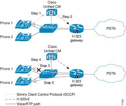
H.323v2 implements Open/Close LogicalChannel and the emptyCapabilitySet features. The use of H.323v2 by H.323 gateways, beginning in Cisco IOS Release 12.0(7)T and Cisco Unified CM Release 3.0 and later, eliminates the requirement for an MTP to provide supplementary services. With Unified CM Release 3.1 and later, a transcoder is allocated dynamically only if required during a call to provide access to G.711-only devices while still maintaining a G.729 stream across the WAN. Full support for H.323v2 is available in Cisco IOS Release 12.1.1T.
Once an H.323v2 call is set up between a Cisco IOS gateway and an IP phone, using the Unified CM as an H.323 proxy, the IP phone can request to modify the bearer connection. Because the Real-Time Transport Protocol (RTP) stream is directly connected to the IP phone from the Cisco IOS gateway, a supported voice codec can be negotiated.
Figure 4-1 and the following steps illustrate a call transfer between two IP phones:
1.
2.
3.
4.
5.
Figure 4-1 H.323 Gateway Supplementary Service Support
MGCP Gateway
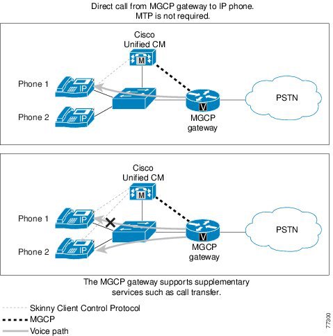
The MGCP gateways provide full support for the hold, transfer, and conference features through the MGCP protocol. Because MGCP is a master/slave protocol with Unified CM controlling all session intelligence, Unified CM can easily manipulate MGCP gateway voice connections. If an IP telephony endpoint (for example, an IP phone) needs to modify the session (for example, transfer the call to another endpoint), the endpoint would notify Unified CM using SCCP. Unified CM then informs the MGCP gateway, using the MGCP User Datagram Protocol (UDP) control connection, to terminate the current RTP stream associated with the Session ID and to start a new media session with the new endpoint information. Figure 4-2 illustrates the protocols exchanged between the MGCP gateway, endpoints, and Unified CM.
Figure 4-2 MGCP Gateway Supplementary Service Support
SIP Gateway
The Unified CM SIP trunk interface to Cisco IOS SIP gateways supports supplementary services such as hold, blind transfer, and attended transfer. The support for supplementary services is achieved via SIP methods such as INVITE and REFER. For more details, refer to the following documentation:
•
•
Unified CM Redundancy
An integral piece of the IP telephony architecture is the provisioning of low-cost, distributed PC-based systems to replace expensive and proprietary legacy PBX systems. This distributed design lends itself to the robust fault tolerant architecture of clustered Unified CMs. Even in its most simplistic form (a two-system cluster), a secondary Unified CM should be able to pick up control of all gateways initially managed by the primary Unified CM.
SCCP Gateways
Upon boot-up, the Cisco VG224, VG248, and ATA 188 gateways are provisioned with Unified CM server information. When these gateways initialize, a list of Unified CMs is downloaded to the gateways. This list is prioritized into a primary Unified CM and secondary Unified CM. In the event that the primary Unified CM becomes unreachable, the gateway registers with the secondary Unified CM.
H.323 VoIP Call Preservation Enhancements for WAN Link Failures
H.323 VoIP call preservation enhancements for WAN link failures sustain connectivity for H.323 topologies where signaling is handled by an entity that is different from the other endpoint, such as a gatekeeper that provides routed signaling or a call agent (such as the Cisco BTS 10200 Softswitch, Cisco PGW 2200 Softswitch, or Cisco Unified CM) that brokers signaling between the two connected parties.
Call preservation is useful when a gateway and the other endpoint (typically a Cisco Unified IP phone) are located at the same site but the call agent is remote and therefore more likely to experience connectivity failures.
Example of H.323 VoIP Call Preservation for All Calls
The following configuration example enables H.323 VoIP call preservation for all calls:
voice service voiph323call preserveMGCP Gateway
MGCP gateways also have the ability to fail over to a secondary Unified CM in the event of communication loss with the primary Unified CM. When the failover occurs, active calls are preserved.
Within the MGCP gateway configuration file, the primary Unified CM is identified using the call-agent <hostname> command, and a list of secondary Unified CM is added using the ccm-manager redundant-host command. Keepalives with the primary Unified CM are through the MGCP application-level keepalive mechanism, whereby the MGCP gateway sends an empty MGCP notify (NTFY) message to Unified CM and waits for an acknowledgement. Keepalive with the backup Unified CMs is through the TCP keepalive mechanism.
If the primary Unified CM becomes available at a later time, the MGCP gateway can "re-home," or switch back to the original Unified CM. This re-homing can occur either immediately, after a configurable amount of time, or only when all connected sessions have been released. This is enabled through the following global configuration commands:
ccm-manager redundant-host <hostname1 | ipaddress1 > <hostname2 | ipaddress2>[no] call-manager redundancy switchback [immediate|graceful|delay <delay_time>]SIP Gateway
Redundancy with Cisco IOS SIP gateways can be achieved similarly to H.323. If the SIP gateway cannot establish a connection to the primary Unified CM, it tries a second Unified CM defined under another dial-peer statement with a higher preference.
By default the Cisco IOS SIP gateway transmits the SIP INVITE request 6 times to the Unified CM IP address configured under the dial-peer. If the SIP gateway does not receive a response from that Unified CM, it will try to contact the Unified CM configured under the other dial-peer with a higher preference.
Cisco IOS SIP gateways wait for the SIP 100 response to an INVITE for a period of 500 ms. By default, it can take up to 3 seconds for the Cisco IOS SIP gateway to reach the backup Unified CM. You can change the SIP INVITE retry attempts under the sip-ua configuration by using the command retry invite <number>. You can also change the period that the Cisco IOS SIP gateway waits for a SIP 100 response to a SIP INVITE request by using the command timers trying <time> under the sip-ua configuration.
One other way to speed up the failover to the backup Unified CM is to configure the command monitor probe icmp-ping under the dial-peer statement. If Unified CM does not respond to an Internet Control Message Protocol (ICMP) echo message (ping), the dial-peer will be shut down. This command is useful only when the Unified CM is not reachable. ICMP echo messages are sent every 10 seconds.
The following commands enable you to configure Unified CM redundancy on a Cisco IOS SIP gateway:
sip-uaretry invite <number>timers trying <time>dial-peer voice 101 voipdestination-pattern 2...session target ipv4:10.1.1.101preference 0monitor probe icmp-pingsession protocol sipv2dial-peer voice 102 voipdestination-pattern 2...session target ipv4:10.1.1.102preference 1monitor probe icmp-pingsession protocol sipv2Site-Specific Gateway Requirements
Each IP Telephony implementation has its own site-specific requirements. The following questions can help you with IP Telephony gateway selection:
•
•
•
•
–
–
–
–
–
•
•
•
•
•
•
•
•
•
•
•
Note
Note
Cisco Unified Communications gateways are able to inter-operate with most major PBX vendors, and they are EIA/TIA-464B compliant.
The site-specific and core gateway requirements are a good start to help narrow the possible choices. Once you have defined the required features, you can make a gateway selection for each of the pertinent configurations, whether they are single-site enterprise deployments of various sizes and complexities or multisite enterprise deployments.
The following tables summarize the features and interface types supported by the various Cisco gateway models.
Note
http://www.cisco.com/en/US/products/sw/voicesw/ps556/prod_software_versions_comparison.htmlCisco Analog Gateways
Table 4-3 lists supported interface types for Cisco analog gateways using H.323 or Session Initiation Protocol (SIP), and Table 4-4 lists supported interface types for Cisco analog gateways using Media Gateway Control Protocol (MGCP).
Table 4-3 Supported Analog H.323 and SIP Features
3800 Series
Yes
Yes
Yes
Yes
Yes
Yes
2800 Series
Yes
Yes
Yes
Yes
Yes
Yes
3700 Series1
Yes
Yes
Yes
Yes
Yes
Yes
Communication Media Module (CMM) 24FXS
Yes
N/A
N/A
N/A
N/A
N/A
CMM-6T1/E1
N/A
N/A
N/A
N/A
N/A
N/A
6608 and 66241
N/A
N/A
N/A
N/A
N/A
N/A
VG224
Yes
N/A
N/A
N/A
N/A
N/A
VG248
No
No
No
No
No
No
Analog Telephone Adapter (ATA)1
Yes
No
No
No
No
No
3600 Series1
Yes
Yes
Yes
Yes
Yes
12.2.11T
2600 Series1
Yes
Yes
Yes
Yes
Yes
12.2.11T
1751 and 17601
Yes
Yes
Yes
Yes
Yes
Yes
VG2001
Yes
Yes
Yes
No
Yes
No
7x00 family
N/A
N/A
N/A
N/A
N/A
N/A
ICS 77501
Yes
Yes
Yes
Yes
Yes
No
Catalyst 4000 Access Gateway Module (AGM)
Yes
Yes
No
No
No
No
827-4V1
Yes
No
No
No
No
No
1 These models have reached End of Sale (EOS).
Table 4-4 Supported Analog MGCP Features
3800 Series
Yes
Yes
No
Yes
No
No
2800 Series
Yes
Yes
No
Yes
No
No
3700 Series1
Yes
Yes
No
Yes
No
No
Communication Media Module (CMM) 24FXS
Yes
N/A
N/A
N/A
N/A
N/A
CMM-6T1/E1
N/A
N/A
N/A
N/A
N/A
N/A
6608 and 66241
Yes
No
No
No
No
No
VG224
Yes
No
No
No
No
No
VG248
No
No
No
No
No
No
Analog Telephone Adapter (ATA)1
Yes
N/A
N/A
N/A
N/A
N/A
3600 Series1
Yes
Yes
No
Yes
No
No
2600 Series1
Yes
Yes
No
Yes
No
No
1751 and 17601
Yes
Yes
No
Yes
No
No
VG2001
Yes
Yes
No
Yes
No
No
7x00 family
N/A
N/A
N/A
N/A
N/A
N/A
ICS 77501
Yes
Yes
No
No
No
No
Catalyst 4000 Access Gateway Module (AGM)1
Yes
Yes
No
No
No
No
827-4V1
No
No
N/A
N/A
N/A
N/A
1 These models have reached End of Sale (EOS).
Cisco Digital Gateways
Table 4-5 through Table 4-8 list supported interface types for Cisco digital gateways using H.323 or Session Initiation Protocol (SIP). Table 4-9 lists supported interface types for Cisco digital gateways using Media Gateway Control Protocol (MGCP).
Table 4-5 Supported Digital H.323 and SIP Features for BRI, T1 CAS, T1 FGB, T1 FGD, and T1 QSIG
3800 Series
Yes
Yes
Yes
No
Yes
No
Yes
Yes
2800 Series
Yes
Yes
Yes
No
Yes
No
Yes
Yes
3700 Series1
Yes
Yes
Yes
No
Yes
No
Yes
Yes
Communication Media Module (CMM) 24FXS
N/A
N/A
N/A
N/A
N/A
N/A
N/A
N/A
CMM-6T1/E1
N/A
N/A
N/A
N/A
Yes
No
No
Yes
6608 and 66241
N/A
N/A
N/A
N/A
No
No
No
No
VG224
N/A
N/A
N/A
N/A
N/A
N/A
N/A
N/A
VG248
No
No
No
No
No
No
No
No
Analog Telephone Adapter (ATA)1
No
No
No
No
No
No
No
No
3600 Series1
Yes
Yes
Yes
No
Yes
No
Yes
Yes
2600 Series1
Yes
Yes
Yes
No
Yes
No
Yes
Yes
1751 and 17601
No
Yes
Yes
No
Yes
No
No
Yes
VG2001
Yes
Yes
No
No
Yes
No
Yes
No
7x00 family
N/A
N/A
N/A
N/A
Yes
No
Yes
Yes
ICS 77501
Yes
Yes
No
No
Yes
No
Yes
No
Catalyst 4000 Access Gateway Module (AGM)1
Yes
No
Yes
No
Yes
No
Yes
Yes
827-4V1
No
No
No
No
No
No
No
No
1 These models have reached End of Sale (EOS).
Table 4-6 Supported Digital H.323 and SIP Features for T1 PRI SL-1, 4ESS, and 5ESS
3800 Series
Yes
No
Yes
Yes
Yes
Yes
2800 Series
Yes
No
Yes
Yes
Yes
Yes
3700 Series1
Yes
No
Yes
No
Yes
No
Communication Media Module (CMM) 24FXS
N/A
N/A
N/A
N/A
N/A
N/A
CMM-6T1/E1
Yes
Yes
Yes
Yes
Yes
Yes
6608 and 66241
No
No
No
No
No
No
VG224
N/A
N/A
N/A
N/A
N/A
N/A
VG248
No
No
No
No
No
No
Analog Telephone Adapter (ATA)1
No
No
No
No
No
No
3600 Series1
Yes
No
Yes
Yes
Yes
Yes
2600 Series1
Yes
No
Yes
Yes
Yes
Yes
1751 and 17601
Yes
No
Yes
No
Yes
No
VG2001
Yes
No
Yes
No
Yes
No
7x00 family
Yes
No
Yes
No
Yes
No
ICS 77501
Yes
No
Yes
No
Yes
No
Catalyst 4000 Access Gateway Module (AGM)1
Yes
No
Yes
No
Yes
No
827-4V1
No
No
No
No
No
No
1 These models have reached End of Sale (EOS).
Table 4-7 Supported Digital H.323 and SIP Features for T1 PRI NI2, NFAS, and Network Specific Facilities (NSF) Service
3800 Series
Yes
Yes
Yes
Yes
Yes
Yes
2800 Series
Yes
Yes
Yes
Yes
Yes
Yes
3700 Series1
Yes
Yes
Yes
Yes
Yes
Yes
Communication Media Module (CMM) 24FXS
N/A
N/A
N/A
N/A
N/A
N/A
CMM-6T1/E1
Yes
Yes
Yes
Yes
Yes
No
6608 and 66241
No
No
No
No
No
No
VG224
N/A
N/A
N/A
N/A
N/A
N/A
VG248
No
No
No
No
No
No
Analog Telephone Adapter (ATA)1
No
No
No
No
No
No
3600 Series1
Yes
Yes
Yes
Yes
Yes
Yes
2600 Series1
Yes
Yes
Yes
Yes
Yes
Yes
1751 and 17601
Yes
Yes
No
No
No
No
VG2001
Yes
Yes
No
No
No
No
7x00 family
Yes
Yes
No
No
No
No
ICS 77501
Yes
Yes
Yes
Yes
Yes
No
Catalyst 4000 Access Gateway Module (AGM)1
Yes
Yes
No
No
No
No
827-4V1
No
No
No
No
No
No
1 These models have reached End of Sale (EOS).
Table 4-8 Supported Digital H.323 and SIP Features for E1 and J1
3800 Series
Yes
Yes
Yes
Yes
Yes
Yes
Yes
2800 Series
Yes
Yes
Yes
Yes
Yes
Yes
Yes
3700 Series1
Yes
Yes
Yes
Yes
Yes
Yes
Yes
Communication Media Module (CMM) 24FXS
N/A
N/A
N/A
N/A
N/A
N/A
N/A
CMM-6T1/E1
No
No
Yes
Yes
Yes
Yes
N/A
6608 and 66241
No
No
No
No
No
No
No
VG224
N/A
N/A
N/A
N/A
N/A
N/A
N/A
VG248
No
No
No
No
No
No
No
Analog Telephone Adapter (ATA)1
No
No
No
No
No
No
No
3600 Series1
Yes
Yes
Yes
Yes
Yes
Yes
Yes
2600 Series1
Yes
Yes
Yes
Yes
Yes
Yes
Yes
1751 and 17601
No
No
Yes
Yes
Yes
Yes
No
VG2001
No
Yes
Yes
Yes
Yes
No
Yes
7x00 family
Yes
No
Yes
Yes
Yes
Yes
No
ICS 77501
No
No
Yes
Yes
Yes
No
No
Catalyst 4000 Access Gateway Module (AGM)1
No
No
Yes
Yes
Yes
Yes
No
827-4V1
No
No
No
No
No
No
No
1 These models have reached End of Sale (EOS).
Table 4-9 Supported Digital MGCP Features
3800 Series
12.4(2)T
Yes3
Yes
Yes3
Yes3
Yes3
Yes3
2800 Series
12.4(2)T
Yes3
Yes for 2811, 2821, 2851
Yes3
Yes3
Yes3
Yes3
3700 Series2
12.4(2)T
Yes3
Yes
Yes3
Yes3
Yes3
Yes3
Communication Media Module (CMM) 24FXS
N/A
N/A
Yes
N/A
N/A
N/A
N/A
CMM-6T1/E1
N/A
Yes
Yes
Yes
Yes
Yes
Yes
66082
N/A
Yes
Yes - E&M only
Yes
Yes
Yes
Yes
66242
N/A
N/A
N/A
N/A
N/A
N/A
N/A
VG224
N/A
N/A
N/A
N/A
N/A
N/A
N/A
VG248
N/A
N/A
N/A
N/A
N/A
N/A
N/A
Analog Telephone Adapter (ATA)2
N/A
N/A
N/A
N/A
N/A
N/A
N/A
3600 Series2
12.4(2)T
Yes3
Yes
Yes3
Yes3
Yes3
Yes3
2600 Series2
12.4(2)T
Yes3
Yes for 2600XM only
Yes3
Yes3
Yes3
Yes3
1751 and 17602
12.3(14)T
Yes
N/A
Yes
Yes
Yes
Yes
VG2002
No
Yes
N/A
Yes
Yes
Yes
Yes
7x00 family
N/A
No
N/A
No
No
No
No
ICS 7750
12.3.7T
Yes
N/A
Yes
Yes
Yes
Yes
Catalyst 4000 Access Gateway Module (AGM)2
No
Yes
N/A
Yes
Yes
Yes
Yes
827-4V2
N/A
N/A
N/A
N/A
N/A
N/A
N/A
1 Cisco IOS Release 12.4(2)T supports BRI MGCP with the following hardware: NM-HDV2, NM-HD-XX and on-board H-WIC slots. BRI MGCP is also supported on older Cisco IOS releases with NM-1V/2V hardware.
2 These models have reached End of Sale (EOS).
3 AIM-VOICE-30 modules require Cisco IOS Release 12.2.13T to support MGCP.
QSIG Support
QSIG is a suite of international standards designed to provide flexibility in connecting PBX equipment to a corporate network. Among its other features, QSIG provides an open, standards-based method for interconnecting PBX equipment from different vendors.
ECMA QSIG is currently supported in H.323 gateways in PBX-to-PBX mode. The H.323 gateways provide full QSIG feature transparency for QSIG information elements. Basic call setup and teardown are supported using H.323 QSIG gateways, as summarized in Table 4-10.
Table 4-10 QSIG Support on H.323 Gateways
Cisco 3800
BRI and T1/E1 QSIG
12.3.11T
Cisco 2800 Series
BRI and T1/E1 QSIG
12.3.8T4
Cisco 37001
T1/E1 QSIG
12.2.8T
Cisco AS5350XM
Cisco AS5400XM
T1/E1
12.2.2T
Cisco 53001
T1/E1
12.0.7T
Cisco 2600XM and 3600 Series1
BRI and T1/E1 QSIG
12.1.2T
Cisco 1751 and 17601
BRI
T1/E1 QSIG
12.2(8)YH
12.2(4)YB
Cisco 7200
T1/E1 QSIG
12.1.2T
1 These models have reached End of Sale (EOS).
For more information on QSIG support on Cisco IOS gateways, refer to the documentation at
Prior to Cisco Unified CM Release 3.3, basic PRI functionality is all that is provided whenever a PBX is connected to a gateway using QSIG via H.323 and calls are made between phones on the PBX and IP phones attached to the Unified CM. This basic functionality, which includes only the Calling Line Identifier (CLID) and Direct Inward Dialed (DID) number, is provided by the gateway terminating the QSIG protocol rather than by Unified CM.
For Unified CM to support QSIG functionality, QSIG must be back-hauled directly to Unified CM. This support is provided in Cisco Unified CM Release 3.3 and later, in conjunction with all MGCP T1/E1 ISDN gateways.
Fax and Modem Support
This section describes the fax and modem support available with Unified CM and Cisco voice gateways. This section first presents brief overviews of fax and modem support on Cisco voice gateways, followed by a listing of supported platforms and example configuration files.
Gateway Support for Fax Pass-Through and Fax Relay
Fax over IP enables interoperability of traditional analog fax machines with IP Telephony networks. The fax image is converted from an analog signal and is carried as digital data over the packet network.
In its original form, fax data is digital. However, to transmit across a traditional PSTN, it is modulated and converted to analog. Fax over IP reverses this analog conversion, transmitting digital data over the packet network and then reconverting the digital data to analog for the receiving fax machine.
Most Cisco voice gateways currently support two methods to transmit fax traffic across the IP network:
•
•
Fax relay mode is the preferred method to transmit fax traffic. However, if a specific gateway does not support fax relay, it supports fax pass-through.
Best Practices
The following recommendations and guidelines can assist you in best implementing fax support on Cisco voice gateways:
•
–
–
–
For detailed information about implementing QoS in a Cisco Unified Communications network, refer to the Enterprise QoS Solution Reference Network Design Guide, available at
•
–
–
•
The only non-IOS gateway that does not support fax relay is the Cisco Digital Access DT-24/DE-30+. If you connect this gateway to a Cisco IOS gateway, you should configure both gateways to use fax pass-through mode.
•
•
•
•
Gateway Support for Modem Pass-Through and Modem Relay
In general, there are two mechanisms for supporting modem sessions over an IP network using voice gateways:
•
•
Currently, both modem relay and modem pass-through are supported on Cisco voice gateways.
Modem pass-through is the transport of modem signals through a packet network using pulse code modulation (PCM) encoded packets and a G.711 codec. Modem pass-through requires the ability of the gateways to discriminate between modem signals and voice signals and take appropriate action. When the gateway detects the modem signal, it disables the following services:
•
•
In modem pass-through mode, the terminating gateway will upspeed to G.711 upon detection of the modem tone. The configuration for modem pass-through and fax pass-through is done with the same command, modem passthrough. The modem traffic is transparently carried over a QoS-enabled IP infrastructure, and at no point is the data demodulated within the IP network.
Modem upspeed is similar to pass-through in the sense that the modem call is carried in-band over the "voice" call. The difference is that the gateways are, to some extent, aware of the modem call when the upspeed feature is used. Although relay mechanisms are not employed, the gateways do recognize the modem tone, automatically change the "voice" codec to G.711 (the upspeed portion), and turn off VAD and echo cancellation (EC) for the duration of the call.
Currently, this upspeed feature is not supported on any Cisco IOS platform except the Cisco AS5300 via Cisco IOS Release 12.1.3T. For Cisco 2600XM, 3700, VG224, and Catalyst 4000 Access Gateway Module (AGM) platforms, the modem upspeed feature will be supported in a future Cisco IOS release. For these platforms, you can configure no vad on the dial peer until the modem upspeed feature becomes available.
The modem upspeed feature is also supported on the Catalyst 6000 gateway modules.
Best Practices
Observe the following recommended best practices to ensure optimum performance of modem traffic transported over an IP infrastructure:
•
–
–
–
For more information, refer to the Enterprise QoS Solution Reference Network Design Guide, available at
•
•
•
•
•
V.90 Support
Currently, Cisco equipment supports only V.34 modems. Although V.90 modems will function on existing hardware, and speeds higher than V.34 speeds can be achieved, full V.90 support cannot be guaranteed.
Super-Group 3 Fax Support
Cisco IOS gateways with Cisco IOS Release 12.4.4T support Super-Group 3 fax; however, only Group 3 speeds are negotiated.
Supported Platforms and Features
The following Cisco platforms support fax and modem features:
Analog Gateways
Cisco IOS Gateways:
•
•
•
•
•
•
•
•
Non-IOS Gateways:
•
•
•
Digital Gateways
Cisco IOS Gateways:
•
•
•
•
•
•
•
•
•
•
Non-IOS Gateways:
•
Note
Platform Protocol Support
Common call control protocols used today in enterprise solutions include H.323, Session Initiation Protocol (SIP), Media Gateway Control Protocol (MGCP), and Skinny Client Control Protocol (SCCP). Not all Cisco voice platforms support all of these protocols or all of the fax and modem features, thus raising interoperability issues. Additional interoperability issues occur when mixing Cisco IOS gateways, such as the Cisco 2600XM or the Cisco 3700 Series, with non-IOS gateways such as the VG248. This section lists the combinations of gateways that provide support for interoperability of fax, modem, and protocol features.
Some of the common combinations of protocols in a network include: MGCP and H.323; SCCP and H.323; SCCP and SIP; MGCP and SIP; H.323 and SIP; and SCCP and MGCP. Common voice gateways included the Cisco VG224, VG248, 2600XM, 2800, 3700, 3800, and Catalyst 6000.
Table 4-11 lists the protocol combinations that currently support fax and modem interoperability.
Note
Gateway Combinations and Interoperability of Features
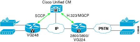
The most frequent questions about fax and modem interoperability arise from combining a Cisco IOS gateway (such as a Cisco 2800 or 3800) with a non-IOS gateway (such as a Cisco VG248), as illustrated in Figure 4-3.
Figure 4-3 Configuration Combining a Cisco IOS and Non-IOS Gateway
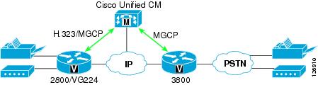
The second most common source of questions about fax and modem interoperability arise in configurations using only Cisco IOS gateways, as illustrated in Figure 4-4.
Figure 4-4 Configuration Using Only Cisco IOS Gateways
Feature Support Between Similar Gateways
Table 4-12 lists the fax and modem features supported between gateways of the same general type, such as between the Cisco VG248 and 6608, between 2600XM and 3700, or between 2600XM and AS5300. In these cases, as long as both platforms support a given feature, those platforms will interoperate.
Gateway Configuration Examples
This section provides listings of example gateway configurations for fax and modem support.
Cisco IOS Gateway Configuration
H.323
!! Cisco fax relay is ON by default!(except for 5350/5400, where Cisco fax relay is not supported)!dial-peer voice 1000 voipdestination-pattern 1Tsession target ipv4:10.10.10.1modem passthrough mode nse codec g711ulaw!!MGCP
!ccm-manager mgcpmgcpmgcp call-agent 10.10.10.1 service-type mgcp version 0.1mgcp modem passthrough voip mode nsemgcp fax t38 inhibit!dial-peer voice 100 potsapplication mgcpappport 1/0/0!Cisco VG248 Configuration
-----------------------------------------------------------| Cisco VG248 (VGC10d8002407) |----- -----------------------------------------------------| Advanced settings ||-----------------------------------------------------|| Allow last good configuration (enabled) || SRST policy (disabled) || SRST provider () || Call preservation (enabled: no timeout) || Media receive timeout (disabled) || Busy out off hook ports (disabled) || DTMF tone dur ------------------------ 100ms) || Echo cancelli| Passthrough signalling |e: use DSP) || Passthrough s|------------------------|) || Hook flash ti| legacy | default>) || Hook flash re| IOS mode | || Fax relay max ------------------------ 14400 bps) || Fax relay playout delay (default: 300) |-----------------------------------------------------------------------------------------------------------------------------------------------------------------| Cisco VG248 (VGC10d8002407) |----- -----------------------------------------------------| Advanced settings ||-----------------------------------------------------|| Allow last good configuration (enabled) || SRST policy (disabled) || SRST provider () || Call preservation (enabled: no timeout) || Media receive timeout (disabled) || Busy out off hook ports (disabled) || DTMF tone duration (default: 100ms) || Echo cancelling policy (alternate: use DSP) || Passthrough signalling (IOS mode) || Hook flash timer (<country default>) || Hook flash reject period (none) || Fax relay maximum speed (default: 14400 bps) || Fax relay playout delay (default: 300) |------------------------------------------------------------------------------------------------------Unified CM Configuration for Cisco IOS Gateways
Perform the following steps in Unified CM to configure it for the Cisco IOS gateways (such as the Cisco 6608 and 6624).
Step 1
Step 2
Step 3
Step 4
Step 5
Step 6
This configuration supports voice, Cisco fax relay, and modem pass-through between Cisco VG248, 6608, 6624, and IOS gateways, with the exception of Cisco AS5350 and AS540 gateways (which do not support Cisco fax relay). The configuration also supports a V.34 modem connection in pass-through mode. V.90 modem connections are not guaranteed but are possible, depending on amount of network jitter and clock sync.
Clock Sourcing for Fax and Modem Pass-Through
The clock signal plays a critical role in enabling fax and modem pass-through to work correctly. The gateway clock must synchronize with the PSTN clock, where Stratum clocking is provided. Without this clock synchronization, fax and (especially) modem pass-through will not work. To synchronize the clocks correctly, enter the following configuration in the T1 controller. (In this example, the T1 controller is the voice gateway that connects to the PSTN.)
!controller T1 0framing esflinecode b8zsclock source linechannel-group 1 timeslots 1-24 speed 64!Also enter this configuration in all other interfaces connected to the PSTN.
T.38 Fax Relay
T.38 fax relay is not supported on Cisco ATA 188, VG248, 6608, and 6624 gateways, but it is supported on most of the high-performance Cisco IOS voice platforms such as the Cisco 2800 and 3800 Series Routers. When operating in either H.323 or SIP mode, these platforms do not support MGCP.
You can configure T.38 fax relay in any of the following ways:
•
•
•
Loose Gateway Controlled with Named Service Event (NSE)
This configuration uses static T.38 configuration on the dial-peer, as illustrated in the following Cisco IOS gateway configuration example:
H.323
!dial-peer voice 1000 voipdestination-pattern 1Tsession target ipv4:10.10.10.1modem passthrough mode nse codec g711ulawfax protocol t38!!MGCP
!ccm-manage mgcpmgcpmgcp call-agent 10.10.10.1 service-type mgcp version 0.1mgcp modem passthrough voip mode nseno mgcp fax t38 inhibit!dial-peer voice 100 potsapplication mgcpappport 1/0/0!!Gateway Controlled with Capability Exchange Through H.245 or Session Description Protocol (SDP)
The following characteristics apply to this method of configuring T.38 fax relay:
•
•
•
–
–
–
The following example illustrates this type of configuration:
H.323
!dial-peer voice 1000 voipdestination-pattern 1Tsession target ipv4:10.10.10.1modem passthrough mode nse codec g711ulaw!! To enable T.38 fax relay and fall back to Cisco fax relay when! T.38 fax negotiation fails. This is the default case.fax protocol t38 fallback cisco!dial-peer voice 1001 voipdestination-pattern 2Tsession target ipv4:10.10.10.2modem passthrough mode nse codec g711ulaw!! To enable T.38 fax relay and fall back to fax passthrough when! T.38 fax negotiation fails.fax protocol t38 nse fallback pass-through!dial-peer voice 1002 voipdestination-pattern 3Tsession target ipv4:10.10.10.3modem passthrough mode nse codec g711ulaw!! This CLI is needed when talking to MGCP endpoint where CA/GK! doesn't support T.38 fax relay such as CCM.fax protocol t38 nse force fallback none!!MGCP
!ccm-manage mgcpmgcpmgcp call-agent 10.10.10.1 service-type mgcp version 0.1mgcp modem passthrough voip mode nseno mgcp fax t38 inhibit!! This CLI is needed when CA doesn't support T.38 fax relaymgcp fax t38 gateway force!dial-peer voice 100 potsapplication mgcpappport 1/0/0!!In topologies that employ the Cisco VG248 and 6608 or 6624, use the following Cisco IOS commands:
fax protocol t38 [nse [force]] fallback [cisco | none]modem passthrough nse codec {g711ulaw|g711alaw}These two commands enable Cisco IOS gateways to interoperate with the VG248 for Cisco fax relay and modem pass-through as well as with other Cisco IOS gateways for T.38 fax relay and modem pass-through.
Call-Agent-Controlled T.38 with H.323 Annex D
The following characteristics apply to this method of configuring T.38 fax relay:
•
•
•
•
•
The following example illustrates this type of configuration:
H.323
!dial-peer voice 1000 voipdestination-pattern 1Tsession target ipv4:10.10.10.1modem passthrough mode nse codec g711ulaw!! To enable T.38 fax relay.fax protocol t38!!MGCP
!ccm-manager mgcpmgcpmgcp call-agent 10.10.10.1 service-type mgcp version 0.1!! T.38 fax relay is ON by default. HOWEVER, Unified CM doesn't! support CA controlled mode. This is the configuration for! talking to BTS.!dial-peer voice 100 potsapplication mgcpappport 1/0/0!Gateways for Video Telephony
Cisco offers voice gateway functionality in a variety of forms, such as standalone devices, modules that integrate into Cisco IOS Routers, or line cards that integrate into Cisco Catalyst Ethernet Switches. These gateways support multiple VoIP protocols (such as H.323, MGCP, SIP, and SCCP), multiple port interface types (such as FXS, FXO, E&M, T1/E1-CAS, T1/E1-PRI, ISDN BRI, and so on), and a myriad of advanced VoIP features. They also offer a rich set of management and troubleshooting interfaces. However, Cisco Voice Gateways do not support the H.320 protocol suite or the H.26x family of video codecs and, therefore, cannot be used for video calls. For this reason, Cisco offers a separate family of video-capable gateways under the IP/VC 3500 Series portfolio.
The IP/VC gateways, while excellent for video calls, do not support all of the features that Cisco Voice Gateways offer. The IP/VC gateways have the following characteristics:
•
•
•
•
•
•
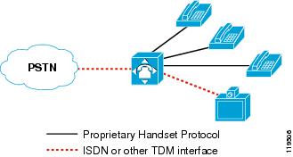
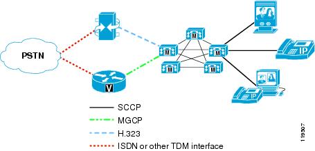
As a result of these differences in the products, Cisco Unified Videoconferencing 3500 Series gateways are not recommended as replacements for Cisco Voice Gateways. IP Telephony customers who want to add video to their communications environment should purchase both types of gateways and use the Cisco Voice Gateways for all voice calls and use the Cisco Unified Videoconferencing 3500 Series gateways for video calls only. The customer might also have to procure separate voice and video circuits from their PSTN service provider, depending on which model of Cisco IOS Gateway they are deploying. For example, you cannot have a single T1-PRI circuit from the Central Office (CO) and share that line for both voice and video calls. In the previous generation of H.320 videoconferencing, these lines were often shared, as depicted in Figure 4-5. With IP Video Telephony, PSTN lines can no longer be shared due to the need for separate voice and video gateways, as depicted in Figure 4-6.
Figure 4-5 Traditional PBX Sharing PSTN Lines Between Voice and H.320 Videoconferencing
Figure 4-6 Unified CM System with Separate PSTN Lines for Voice and IP Video Telephony
With separate voice and video gateways, the route plans must also be separate for both inbound and outbound calls. For inbound calls, there is no way to have a single Direct Inward Dial (DID) extension for a user who wants to be able to receive both voice and video calls. Typically, each user will already have a DID for voice calls. When you introduce video into the scenario, users will have to be dialed some other way, such as via a second DID number or by dialing the main number of the video gateway and then entering the users video extension when prompted by the Interactive Voice Response (IVR). For outbound calls, there is no way to have a single PSTN access code for both voice and video calls. Typically, users will already have a well-known access code for voice (such as 9 in most US enterprises), but when you introduce video into the scenario, they will have to dial some other access code to place outbound video calls.
Another consideration for deploying two types of gateways is the placement of those gateways. Typically, enterprises have many PSTN gateway resources consolidated at their central site(s), and each branch office has some local gateway resources as well. For instance, Cisco Catalyst 6500 gateways may be deployed at the central site with several T1/E1 circuits connected to them, while Cisco Integrated Services Routers (ISRs) may be deployed at each branch office with either analog or digital trunks to the local CO. When video is introduced into this scenario, the customer must also determine the number of PSTN circuits they will need for video and where the video gateways will be placed. For instance, will they deploy only a few IP/VC 3500 Series gateways at the central site, or will they also deploy them at each branch office?
Finally, consider how calls will be routed across the IP network to a remote gateway for the purpose of providing toll bypass, and how calls will be re-routed over the PSTN in the event that the IP network is unavailable or does not have enough bandwidth to complete the call. More specifically, do you want to invoke automated alternate routing (AAR) for video calls?
Routing Inbound Calls from the PSTN
Use one of the following methods to route inbound calls from the PSTN:
•
•
Note
The following example illustrates the second method:
A user has a Cisco Unified IP Phone 7960 attached to a PC running Cisco Unified Video Advantage. The extension of the IP Phone is 51212, and the fully qualified DID number is 1-408-555-1212. To reach the user from the PSTN for a voice-only call, people simply dial the DID number. The CO sends calls to that DID number through T1-PRI circuit(s) connected to a Cisco Voice Gateway. When the call is received by the gateway, Unified CM knows that the gateway is capable of audio only, so it negotiates only a single audio channel for that call. Conversely, for people to reach the user from the PSTN for a video call, they must dial the main number of the video gateway and then enter the user's extension. For example, they might dial 1-408-555-1000. The CO would send calls to that number through the T1-PRI circuit(s) connected to a Cisco Unified Videoconferencing 3500 Series video gateway. When the call is received by the gateway, an IVR prompt asks the caller to enter the extension of the person they are trying to reach. When the caller enters the extension via DTMF tones, Unified CM knows that the gateway is capable of video, so it negotiates both audio and video channels for that call.
Gateway Digit Manipulation
The Cisco Unified Videoconferencing 3500 Series Gateways cannot manipulate digits for calls received from the PSTN. It takes the exact number of digits passed to it in the Q.931 Called Party Number field and sends them all to Unified CM. Therefore, Unified CM must manipulate the digits in order to match the directory number (DN) of the destination device. For instance, if the circuit from the CO switch to the gateway is configured to pass 10 digits but the extension of the called party is only five digits, Unified CM must strip off the leading five digits before attempting to find a matching DN. You can implement this digit manipulation in one of the following ways:
•
This method enables you to instruct Unified CM to pay attention to only the least-significant N digits of the called number. For example, setting the Significant Digits to 5 will cause Unified CM to ignore all but the last 5 digits of the called number. This is the easiest approach, but it affects all calls received from that gateway. Thus, if you have variable-length extension numbers, this is not the recommended approach.
•
This method enables Unified CM to match calls to the full number of digits received, to modify the called number, and then to continue performing digit analysis on the resulting modified number. This approach is slightly more complex than the preceding method, but it is more flexible and enables you to use a finer granularity for matching calls and for specifying how they will be modified.
Routing Outbound Calls to the PSTN
Use one of the following methods to route outbound calls to the PSTN:
•
•
Gateway Service Prefixes
The Cisco Unified Videoconferencing Gateways use service prefixes to define the speed for outbound calls. When you configure a service prefix in the gateway, you must choose one of the following speeds:
•
•
•
•
•
•
Note
Calls from an IP endpoint toward the PSTN must include the service prefix at the beginning of the called number in order for the gateway to decide which service to use for the call. Optionally, you can configure the default prefix to be used for calls that do not include a service prefix at the beginning of the number. This method can become quite complex because users will have to remember which prefix to dial for the speed of the call they wish to make, and you would have to configure multiple route patterns in Unified CM (one for each speed). Fortunately, the Auto speed enables you to minimize this effort. If the majority of your calls are made using 64 kbps per channel (for example, 128 kbps, 384 kbps, 512 kbps, 768 kbps, and so on), you could use the Auto service in that case. You would then need to create only one other service for the rare case in which someone makes a call using 56 kbps per channel (for example, 112 kbps, 336 kbps, and so on).
Cisco recommends that you always use a # character in your service prefixes because the gateway recognizes the # as an end-of-dialing character. By placing this character in the service prefix, you block people from attempting to use the gateway for toll fraud by dialing the main number of the gateway, reaching the IVR, and then dialing out to an off-net number. The # can either be at the beginning (recommended) or the end of the service prefix. For example, if your access code to reach the PSTN is 8 for video calls, Cisco recommends that you configure the service prefix as #8 or 8#. Or, if you have two service prefixes as described above, you might use #80 for the Auto 64-kbps service and #81 for the Auto 56-kbps service.
The ramification of using a service prefix is that Unified CM must prepend the service prefix to the called number when sending calls to the IP/VC gateway. Because forcing users to dial the # would not be very user-friendly, Cisco recommends that you configure Unified CM to prepend the # to the dialed number. For example, if the access code to dial a video call to the PSTN is 8, you could configure a route pattern as 8.@ in Unified CM, and in the route pattern configuration you would configure the called number translation rule to prepend #8 whenever that route pattern is dialed. Or, if you have two service prefixes as described above, you might use 80.@ for the Auto 64-kbps service (prefixing # to the called number) and 81.@ for the Auto 56-kbps service (prefixing # to the called number).
Automated Alternate Routing (AAR)
When the IP network does not have enough bandwidth available to process a call, Unified CM uses its call admission control mechanism to determine what to do with the call. As described in the chapter on IP Video Telephony, page 16-1, Unified CM performs one of the following actions with the call, depending on how you have configured it:
•
•
•
The first two options are covered in the chapter on IP Video Telephony, page 16-1, and this section covers the AAR option.
To provide AAR for voice or video calls, you must configure the calling and called devices as members of an AAR group and configure an External Phone Number Mask for the called device. The External Phone Number Mask designates the fully qualified E.164 address for the user's extension, and the AAR group indicates what digits should be prepended to the External Phone Number Mask of the called device in order for the call to route successfully over the PSTN.
For example, assume that user A is in the San Jose AAR group and user B is in the San Francisco AAR group. User B's extension is 51212, and the External Phone Number Mask is 6505551212. The AAR groups are configured to prepend 91 for calls between the San Jose and San Francisco AAR groups. Thus, if user A dials 51212 and there is not enough bandwidth available to process the call over the IP WAN between those two sites, Unified CM will take user B's External Phone Number Mask of 6505551212, prepend 91 to it, and generate a new call to 916505551212 using the AAR calling search space for user A.
This same logic applies to video calls as well, with one additional step in the process. For video-capable devices, there is field called Retry Video Call as Audio. As described in the chapter on IP Video Telephony, page 16-1, if this option is enabled (checked), Unified CM does not perform AAR but retries the same call (that is, the call to 51212) as a voice-only call instead. If this option is disabled (unchecked), Unified CM performs AAR. By default, all video-capable devices in Unified CM have the Retry Video Call as Audio option enabled (checked). Therefore, to provide AAR for video calls, you must disable (uncheck) the Retry Video Call as Audio option. Additionally, if a call admission control policy based on Resource Reservation Protocol (RSVP) is being used between locations, the RSVP policy must be set to Mandatory for both the audio and video streams.
Furthermore, Unified CM looks at only the called device to determine whether the Retry Video Call as Audio option is enabled or disabled. So in the scenario above, user B's phone would have to have the Retry Video Call as Audio option disabled in order for the AAR process to take place.
Finally, devices can belong to only one AAR group. Because the AAR groups determine which digits to prepend, AAR groups also influence which gateway will be used for the rerouted call. Depending on your choice of configuration for outbound call routing to the PSTN, as discussed in the previous section, video calls that are rerouted by AAR might go out a voice gateway instead of a video gateway. Therefore, carefully construct the AAR groups and the AAR calling search spaces to ensure that the correct digits are prepended and that the correct calling search space is used for AAR calls.
While these considerations can make AAR quite complex to configure in a large enterprise environment, AAR is easier to implement when the endpoints are strictly of one type or the other (such as IP Phones for audio-only calls and systems such as the Tandberg T-1000 dedicated for video calls). When endpoints are capable of both audio and video calls (such as Cisco Unified Video Advantage or a Cisco IP Video Phone 7985G), the configuration of AAR can quickly become unwieldy. Therefore, Cisco recommends that large enterprise customers who have a mixture of voice and video endpoints give careful thought to the importance of AAR for each user, and use AAR only for select video devices such as dedicated videoconference rooms or executive video systems. Table 4-13 lists scenarios when it is appropriate to use AAR with various device types.
Least-Cost Routing
Least-cost routing (LCR) and tail-end hop-off (TEHO) are very popular in VoIP networks and can be used successfully for video calls as well. In general, both terms refer to a way of configuring the call routing rules so that calls to a long-distance number are routed over the IP network to the gateway closest to the destination, in an effort to reduce toll charges. (For Cisco Unified CM Release 4.1, LCR basically means the same thing as TEHO.) Unified CM supports this feature through its rich set of digit analysis and digit manipulation capabilities, including:
•
•
•
•
Configuring LCR for video calls is somewhat more complicated than for voice calls, for the following reasons:
•
•
With respect to dedicated gateways, the logic behind why you might or might not decide to use LCR for video calls is very similar to that explained in the section on Automated Alternate Routing (AAR). Due to the need to have different types of gateways for voice and video, it can become quite complex to configure all the necessary partitions, calling search spaces, translation patterns, route patterns, route filters, route lists, and route groups needed for LCR to route voice calls out one gateway and video calls out another.
With respect to bandwidth requirements, the decision to use LCR depends on whether or not you have enough available bandwidth on your IP network to support LCR for video calls to/from a given location. If the current bandwidth is not sufficient, then you have to determine whether the benefits of video calls are worth the cost of either upgrading your IP network to make room for video calls or deploying local gateways and routing calls over the PSTN. For example, suppose you have a central site with a branch office connected to it via a 1.544-Mbps T1 Frame Relay circuit. The branch office has twenty video-enabled users in it. A 1.544-Mbps T1 circuit can handle at most about four 384-kbps video calls. Would it really make sense in this case to route video calls up to the central site in order to save on toll charges? Depending on the number of calls you want to support, you might have to upgrade your 1.544-Mbps T1 circuit to something faster. Is video an important enough application to justify the additional monthly charges for this upgrade? If not, it might make more sense to deploy an IP/VC video gateway at the branch office and not bother with LCR. However, placing local IP/VC gateways at each branch office is not inexpensive either, so ultimately you must decide how important video-to-PSTN calls are to your business. If video is not critical, perhaps it is not worth upgrading the bandwidth or buying video gateways but, instead, using the Retry Video Call as Audio feature to reroute video calls as voice-only calls if they exceed the available bandwidth. Once a call is downgraded to voice-only, local gateway resources and bandwidth to perform LCR become more affordable and easier to configure.
ISDN B-Channel Binding, Rollover, and Busy Out
H.320 video uses multiple ISDN channels bound together to achieve the speeds needed to pass full-motion video. One of the problems with this bonding mechanism is that, when an inbound ISDN video call is received, the gateway does not know how many channels will be requested for that call until after it accepts the call and the source device indicates how many additional channels are required. If there are not enough B-Channels to satisfy the request, the call is disconnected. Therefore, careful traffic engineering is required to minimize the possibility that this situation will occur. Essentially, you want to ensure that there are always enough B-Channels available to handle the next call that might come in.
This B-Channel issue occurs in two cases:
•
•
Inbound Calls
For inbound calls, consider the following scenario:
A company has a Cisco 3526 IP/VC Gateway with an ISDN PRI circuit connecting it to a central office (CO) switch. The ISDN PRI circuit in this case offers 23 B-Channels. A video call is received from the PSTN at 384 kbps. This call takes six B-Channels, leaving 17 available. A second and third 384-kbps call are received on the line while the first one is still active. These each take an additional six channels, leaving five channels available. When the fourth 384-kbps call is received, the gateway will answer the call but, recognizing that it does not have enough B-Channels available (it only has five left but the call requires six), it will disconnect (by sending a Q.931 RELEASE COMPLETE with "16: Normal Call Clearing" as the reason). The caller attempting to make the fourth call will not know why the call failed and might redial the number repeatedly, trying to make the call work.
On Cisco Unified Videoconferencing gateways, you can minimize your chances of running into this issue by configuring the gateway to send a request to the CO to busy-out the remaining B-Channels (in this example, five channels) whenever the gateway reaches a certain threshold of utilization (configured as a percentage of total bandwidth).
In addition, you can have the CO provision multiple ISDN circuits in a trunk group. When the first circuit reaches the busy-out threshold, calls will roll over to the next PRI in the group. The Cisco 3540 IP/VC Gateway offers two ISDN PRI connections and supports bonding channels across both ports. For example, port 1 might have only five channels available while port 2 is sitting idle and, therefore, has 23 channels available. By taking the five channels from port 1 and one channel from port 2 and bonding them together, the fourth 384-kbps call can succeed. This leaves 22 channels available on controller 2, and at some point additional inbound calls would reach the busy-out threshold again. At that point the remaining channels on port 2 will be busied out, and all further inbound calls will be rejected with cause code "Network Congestion." Cisco Unified Videoconferencing gateways cannot bound channels across different gateways or across different Cisco 3540 gateway models in the same Cisco 3544 chassis, so two ports is the maximum that you can bond together. The CO switch can still roll calls over to a third or forth PRI in the trunk group (most COs support trunk groups of up to 6 circuits), but you cannot bond channels between PRI number one and PRI number three, for example, as you can between PRI number one and PRI number two.
The busy-out logic described above depends on the assumption that all calls take place at the same speed. Suppose, for example, that two 384-kbps calls are active on a port and a 128-kbps call came in. This call would take only two channels, using a total of 14 channels for the three calls (6+6+2 = 14) and leaving nine channels available on the circuit. However, if the busy-out threshold is set at 18 channels (assuming that all calls would take place at 384-kbps), only four channels are still available under this busy-out threshold. If another 384 kbps call comes in at this point, the call will fail because the remaining four channels are not enough to support the call. Also, because the busy-out threshold of 18 channels has not been reached yet (only 14 channels are used), the circuit is not busied out and calls will not roll over to the next circuit. This condition will persist until one of the existing calls is disconnected. To avoid such situations, it is important to try to standardize on a single call speed for all calls.
Outbound Calls
Outbound calls encounter the same potential situations as inbound calls, but the way in which the busy-out occurs is different. The Cisco 3500 Series IP/VC Gateways support messages called Resource Availability Indicator and Resource Availability Confirm (RAI/RAC). The RAI/RAC messages are defined under the H.225 RAS specification and are used by the gateways to tell the gatekeeper that they are full and to no longer route any more calls to them. When the gateway reaches the busy-out threshold, it sends an RAI message with a status of True to the gatekeeper. True means "Do not send me any more calls;" False means "I am available." The gateway sends an RAI=False as soon as it is no longer at its busy-out threshold. The busy-out threshold for outbound calls is separate from the busy-out threshold for inbound calls, and you can configure them differently so that inbound calls will roll over to the next available circuit but outbound calls will still be accepted, or vice versa. For example, you could configure the RAI threshold to 12 channels but the ISDN busy-out threshold to 18 channels. When two 384 kbps are active, outbound calls will roll over to the next available gateway, but a third 384-kbps inbound call could still be received. An equally efficient method of achieving outbound call busy-out failover is to use Unified CM's route group and route list construct, as described in the following section, instead of the RAI/RAC method.
Configuring the Gateways in Unified CM
You can configure an IP/VC gateway in either of the following ways in Unified CM:
•
•
If you have only one gateway, it is probably easier to configure it directly in Unified CM instead of going through a trunk to get to it. If you have multiple gateways for load balancing and redundancy, you can either configure them all in Unified CM and place them into a route group(s) and route list, or configure an H.225 trunk to the gatekeeper and rely on RAI/RAC between the gateways and the gatekeeper to tell Unified CM which gateway it should send a given call to.
For inbound calls from the PSTN to Unified CM, the Cisco Unified Videoconferencing gateways can either register with a gatekeeper or be configured with the IP addresses of up to three Unified CM servers to which they should send all inbound call requests. This method is known as peer-to-peer mode. Either way, the goal is have all inbound calls received by the gateways sent to Unified CM so that Unified CM can decide how to route the calls. See Gatekeepers, page 16-22, for more details on how to configure the gatekeeper to route calls from the gateways to Unified CM.
Call Signaling Port Numbers
By default, the Cisco Unified Videoconferencing Gateways listen on TCP port 2720 instead of the well-known port 1720. However, also by default, Unified CM sends H.323 calls to port 1720. You can change the port that the gateway listens on or you can change the port that Unified CM sends to in the H.323 gateway device configuration in Unified CM. Either way, both sides have to match in order for outbound calls to the gateway to succeed.
In the inbound direction, when configured to operate in peer-to-peer mode, the Cisco Unified Videoconferencing Gateways will send the call to Unified CM on port 1720. When configured to register with a gatekeeper, Unified CM uses a randomly generated port number for all gatekeeper-controlled trunks. This method enables Unified CM to have multiple trunks to the same gatekeeper. This port number is included in the Registration Request (RRQ) from Unified CM to the gatekeeper, so the inbound H.225 setup message from the gateway to Unified CM will be sent to this port number. However, if the gateway is configured directly in Unified CM as an H.323 gateway device, Unified CM will ignore the fact that the call came in on the TCP port of the H.225 trunk and will instead match the source IP address to the H.323 gateway device configured in its database. If it does not find a matching device, Unified CM will treat the call as if it came in on the trunk.
In the outbound direction, if Unified CM uses a gatekeeper-controlled H.225 trunk to reach the gateway, the gatekeeper will tell Unified CM which TCP port to use to reach the gateway. If the gateway is configured in Unified CM as an H.323 gateway device (that is, peer-to-peer mode), then Unified CM must be configured to send calls either to port 2720 (default) or to 1720 (if the listening port on the gateway has been modified).
Call Signaling Timers
Due to the delay inherent in H.320 bonding, video calls can take longer to complete than voice calls. Several timers in Unified CM are tuned, by default, to make voice calls process as fast as possible, and they can cause video calls to fail. Therefore, you must modify the following timers from their default values in order to support H.320 gateway calls:
•
•
•
Cisco recommends that you increase each of these timers to 25 by modifying them under the Service Parameters in Unified CM Administration. Note that these are cluster-wide service parameters, so they will affect calls to all types of H.323 devices, including voice calls to existing H.323 Cisco Voice Gateways.
Voice Gateways Bearer Capabilities
H.323 calls use the H.225/Q.931 Bearer Capabilities Information Element (bearer-caps) to indicate what type of call is being made. A voice-only call has its bearer-caps set to "speech" or "3.1 KHz Audio," while a video call has its bearer-caps set to "Unrestricted Digital Information." Cisco voice gateways, some legacy PBXs, and most cellular carriers do not support Unrestricted Digital Information bearer-caps. Therefore, calls to a voice gateway might fail if Unified CM attempts the call as a video call.
Unified CM decides which bearer-caps to set, based on the following factors:
•
•
For example, consider a network in which a video-capable device (such as a Cisco Unified IP Phone with a VT Advantage client associated to it) is configured in the same region as a Cisco voice gateway. When the user dials 9 to access an outside line, Unified CM determines that the calling device is video-capable and that the region is set to allow 384 kbps of video bandwidth. Unified CM then sets the bearer-caps to Unrestricted Digital Information for that call. But because the call is to a Cisco voice gateway, the gateway rejects the call with the cause code "Incompatible Destination." This problem will occur in any network that uses H.323 voice gateways and that has IP Phones associated with Cisco Unified Video Advantage. From the user's perspective, things will appear to work fine before installing Cisco Unified Video Advantage, but calls to the PSTN will fail as soon as the user plugs a PC running Cisco Unified Video Advantage into the IP Phone.
This situation exists only on calls to H.323 voice gateways. If the Cisco voice gateway uses MGCP to communicate with Unified CM, the problem will not occur because Unified CM does not support video on its MGCP protocol stack and because, in MGCP mode, Unified CM has complete control over the D-Channel signaling to the PSTN. Likewise, if the Cisco voice gateway uses SIP to communicate with Unified CM, the problem will not occur then either because Unified CM does not support video on its SIP protocol stack, but even if it did, the gateway would simply need to ignore the video capabilities passed in Unified CM's outgoing Session Description Protocol (SDP) advertisement.
To prevent this situation, configure the bearer-caps on all Cisco H.323 voice gateways by using the bearer-caps command under the voice-port configuration mode, as illustrated in the following example:
gateway#configure terminalgateway(config)#voice-port 1/0:23gateway(config-voiceport)#bearer-caps speech