-
Cisco Unified Communications SRND Based on Cisco Unified Communications Manager 5.x
-
Preface
-
Introduction
-
IP Telephony Deployment Models
-
Network Infrastructure
-
Gateways
-
Cisco Unified Communications Manager Trunks
-
Media Resources
-
Music on Hold
-
Call Processing
-
Call Admission Control
-
Dial Plan
-
Emergency Services
-
Third-Party Voicemail Design
-
Cisco Unity
-
Cisco Unified MeetingPlace Integration
-
Cisco Unified MeetingPlace Express
-
IP Video Telephony
-
LDAP Directory Integration
-
IP Telephony Migration Options
-
Voice Security
-
IP Telephony Endpoints
-
Cisco Unified Presence
-
Cisco Unified Communications Manager Applications
-
Cisco Mobility Applications
-
Recommended Hardware and Software Combinations
-
Glossary
-
Index
-
Table Of Contents
Avoiding Overlap of Extension Dialing
Variable Length On-Net Dial Plan
On-Net and Off-Net Access Codes
User Input on Type-A SIP Phones
User Input on Type-B SIP Phones
Calling Privileges in Unified CM
Digit Manipulation in Unified CM
Establish the PSTN Number of the Destination
Prefix the Required Access Codes
Select the Proper Dial Plan and Route
Special Considerations for Sites Located Within the Same Local Dialing Area
Call Routing in Cisco IOS with H.323 Dial Peers
Call Routing in Cisco IOS with a Gatekeeper
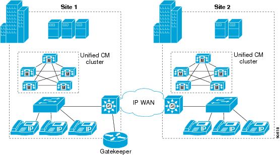
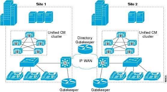
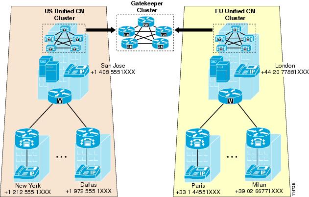
Centralized Gatekeeper Configuration
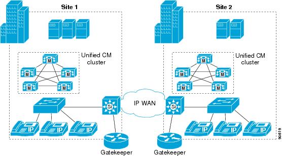
Distributed Gatekeeper Configuration
Distributed Gatekeeper Configuration with Directory Gatekeeper
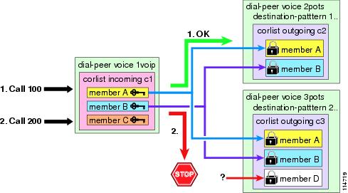
Calling Privileges in Cisco IOS with H.323 Dial Peers
Digit Manipulation in Cisco IOS with H.323 Dial Peers
Design Guidelines for Multisite Deployments
Deploying Uniform On-Net Dial Plans
Inter-Site Calls Within a Cluster
Outgoing PSTN and IP WAN Calls
Deploying Variable-Length On-Net Dial Plans with Partitioned Addressing
Inter-Site Calls Within a Cluster
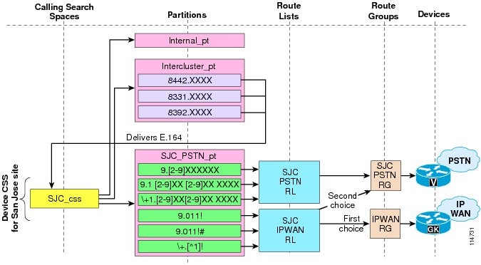
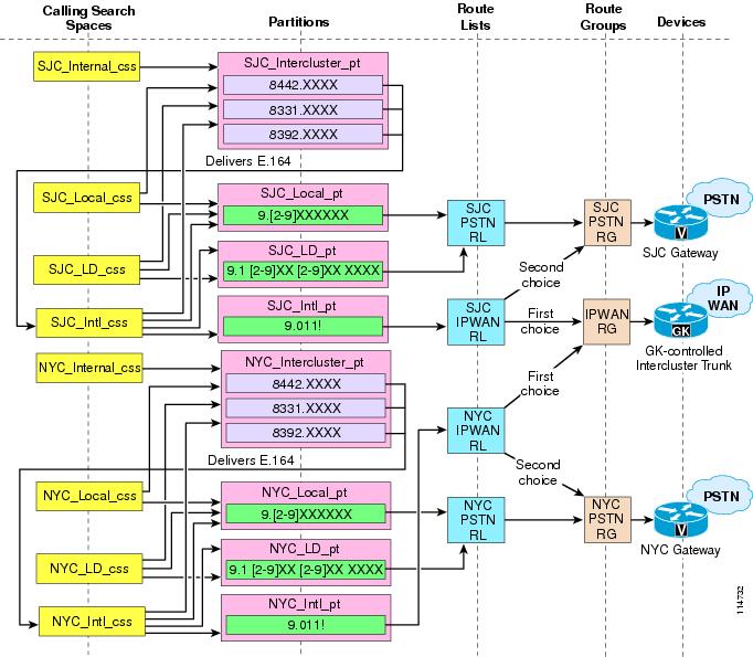
Outgoing PSTN and IP WAN Calls
Deploying Variable-Length On-Net Dial Plans with Flat Addressing
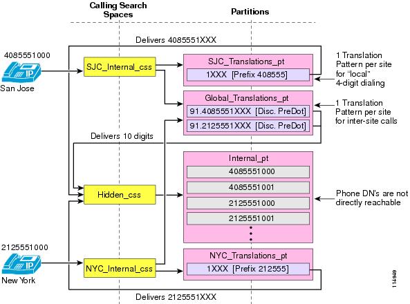
Inter-Site Calls Within a Cluster
Outgoing PSTN and IP WAN Calls
Special Considerations for Deployments Without Site Codes
Deploying Dialed Pattern Recognition in the Phones with Unified CM 5.x
Building Classes of Service for Unified CM with the Traditional Approach
Building Classes of Service for Unified CM with the Line/Device Approach
Guidelines for the Line/Device Approach
Extension Mobility Considerations for the Line/Device Approach
Building Classes of Service in Cisco IOS with H.323
Deploying Call Coverage in a Multisite Centralized Call Processing Model
Deploying Call Coverage in a Multisite Distributed Call Processing Model
Dial Plan
The dial plan is one of the key elements of an IP Telephony system, and an integral part of all call processing agents. Generally, the dial plan is responsible for instructing the call processing agent on how to route calls. Specifically, the dial plan performs the following main functions:
•
Endpoint addressing
Reachability of internal destinations is provided by assigning directory numbers (DNs) to all endpoints (such as IP phones, fax machines, and analog phones) and applications (such as voicemail systems, auto attendants, and conferencing systems)
•
Depending on the calling device, different paths can be selected to reach the same destination. Moreover, a secondary path can be used when the primary path is not available (for example, a call can be transparently rerouted over the PSTN during an IP WAN failure).
•
Different groups of devices can be assigned to different classes of service, by granting or denying access to certain destinations. For example, lobby phones might be allowed to reach only internal and local PSTN destinations, while executive phones could have unrestricted PSTN access.
•
In some cases, it is necessary to manipulate the dialed string before routing the call; for example, when rerouting over the PSTN a call originally dialed using the on-net access code, or when expanding an abbreviated code (such as 0 for the operator) to an extension.
•
Special groups of devices can be created to handle incoming calls for a certain service according to different rules (top-down, circular hunt, longest idle, or broadcast).
This chapter examines the following main aspects of dial plan:
This section analyzes the thought process involved in planning an IP Telephony dial plan, ranging from the number of digits used for internal extensions to the overall architecture of a company's internal dial plan. (Prerequisite: Some familiarity with dial plans in general.)
This section provides detailed explanations of the elements of a Cisco Unified Communications dial plan. Covered topics include call routing logic, calling privileges, and digit manipulation techniques for various Cisco products. (Prerequisite: A working knowledge of Cisco Unified Communications Manager and Cisco IOS is recommended.)
This section contains design and deployment guidelines related to multisite IP Telephony networks, endpoint addressing methods, approaches to building classes of service, and call coverage functionality. (Prerequisite: A working knowledge of Cisco Unified Communications Manager and Cisco IOS is recommended.)
For more details, refer to the Cisco Unified Communications Manager System Guide, the Cisco IOS Voice, Video, and Fax Configuration Guide, Release 12.2, and other product documentation available at
For purposes of this chapter only, we define two types of IP phones:
•
Includes the Cisco Unified IP Phone 7905, 7912, 7940, and 7960.
•
Includes the Cisco Unified IP Phone 7911, 7941, 7961, 7970, and 7971.
Type-A phones differ somewhat from Type-B phones in their behavior, and Type-B phones offer support for Key Press Markup Language (KPML) but Type-A phones do not. (See User Input on Type-A SIP Phones and User Input on Type-B SIP Phones.)
Planning Considerations
The dial plan is the most fundamental attribute of a telephony system. It is at the very core of the user experience because it defines the rules that govern how a user reaches any destination. These rules include:
•
•
•
•
•
•
•
•
A dial plan suitable for an IP telephony system is not fundamentally different from a dial plan designed for a traditional TDM telephony system; however, an IP-based system presents the dial plan architect with some new possibilities. For example, because of the flexibility of IP-based technology, telephony users in separate sites who used to be served by different, independent TDM systems can now be included in one, unified IP-based system. These new possibilities afforded by IP-based systems require some rethinking of the way we look at dial plans. This section examines some of the elements that the system planner must consider to properly establish the requirements that drive the design of the dial plan.
Dialed Pattern Recognition
Digit strings dialed by a user on a telephone generally follow patterns. For instance, many enterprises implement a five-digit abbreviated dialing pattern for calls made within the same office location. Also, many enterprises rely on a single-digit access code to represent outside dialing, followed by some quantity of digits to reach a local PSTN number or a long-distance PSTN number (for example, 9 followed by seven digits to reach a local number, or 9 followed by 1 and ten digits to reach a long-distance destination).
The system administrator must plan the system's recognition of these patterns to ensure that the system will act promptly upon detection of a string that corresponds to a predetermined pattern so that users experience no (or minimal) post-dialing delay.
For phones using the Skinny Client Control Protocol (SCCP) and for SIP phones using the Key Press Markup Language (KPML) during dialing, you can implement pattern recognition in Cisco Unified Communications Manager (Unified CM) by configuring route patterns, translation patterns, phone DNs, and so forth. With each digit dialed by the user, the phone sends a signaling message to Unified CM, which performs the incremental work of recognizing a matching pattern. As each key press from the user input is collected, Unified CM's digit analysis provides appropriate user feedback, such as:
•
•
•
Once digit dialing is completed, Unified CM provides user feedback in the form of call progress tones, such as ringback tone if the destination is in the alerting stage or reorder tone if the destination is invalid.
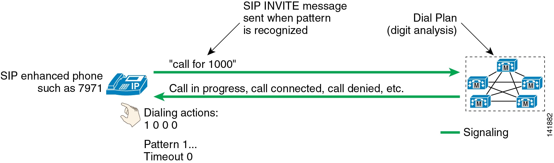
IP phones running the Session Initiation Protocol (SIP) can be configured with pattern recognition instructions called SIP dial rules. When used, they accomplish the bulk of the task of pattern recognition within the phone. Once a pattern is recognized, the SIP phone sends an invitation to Unified CM to place a call to the number corresponding to the user's input. That action, called a SIP INVITE, is subjected to the Unified CM dial plan in the same way a call from an IP phone running the SCCP protocol would be, except that Unified CM's digit analysis is presented with a completed dial string (that is, all of the digits entered by the user are presented as a block to Unified CM for processing). In this mode of operation, user feedback during the dialing of the digit string is limited to what the phone can provide (see SIP Dial Rules). Once the string has been composed, user feedback can still be provided by Unified CM in the form of call progress tones.
On-Net versus Off-Net Dialing
Calls that originate and terminate on the same telephony network are considered to be on-network (or on-net). By contrast, if a call originates in company A and terminates at company B, it probably has to be routed through different telephony networks: first company A's network, followed by the PSTN, and finally into company B's network. From the caller's perspective, the call was routed off-network (or off-net); from the called party's perspective, the call originated off-net.
In TDM systems, the on-net boundaries of a telephony system are established by the PBX or Centrex system, and they typically do not extend outside of a single site. When they do, they typically do not include sites not immediately on the periphery of a large system hub.
One of the key attributes of IP telephony is its ability to expand the boundaries of calls that can be considered on-net. For instance, telephony users in an enterprise with six dispersed branch offices might be used to reaching one colleague with abbreviated dialing (for example, four-digit dialing) if the called party is located in the same site but dialing a full PSTN number to reach another colleague located in a different site. With an IP-based system where all users are served by the same IP network, it now becomes economically feasible to unite all six branches under a four-digit abbreviated dialing plan, with the IP network as the preferred path and automated overflow to the PSTN as a secondary path if the IP network is congested.
Abbreviated Dialing
Consider an extension with direct inward dial (DID) capability, which can be reached directly from the PSTN. An off-net PSTN caller has to dial the fully qualified PSTN number (for example, 1 415 555 1234) to reach a DID extension. An on-net caller might, however, prefer the ability to reach that same extension by simply dialing the last few digits of the DID number. In a four-digit abbreviated dial plan, the on-net caller would dial only 1234 in this example to reach the same extension.
Avoiding Overlap of Extension Dialing
A telephony system must be configured so that any extension can be reached in an unambiguous manner. To accomplish this goal, the dial plan must satisfy the following requirements:
•
•
–
–
Dialing String Length
The number of dialable extensions determines the quantity of digits needed to dial extensions. For example, a four-digit abbreviated dial plan cannot accommodate more than 10000 extensions (from 0000 to 9999). If 0 and 9 are reserved as operator code and off-net access code, respectively, the number range is further reduced to 8000 (1000 to 8999).
Uniform On-Net Dial Plan
A dial plan can be designed so that all extensions within the system are reached in a uniform way; that is, a fixed quantity of digits is used to reach a given extension from any on-net origination point. Uniform dialing is desirable because of the simplicity it presents to users. A user does not have to remember different ways to dial a number when calling from various on-net locations.
For example, if phone A is reached by dialing 1234 from any on-net location, whether the calling phone is in the same office or at a different site, the enterprise's dial plan is deemed uniform.
When the enterprise consists of few sites, this approach can be used with few complications. The larger the enterprise, in terms of number of extensions and sites, the more of the following challenges it faces in designing a uniform dial plan:
•
•
•
Once a given quantity of digits has been selected and the requisite ranges have been excluded (for example, ranges beginning with 9 or 0), the remaining dialing space has to be divided between all sites.
Most systems require that two ranges be excluded, thus leaving eight different possibilities for the leading digit of the dial range. Table 10-1 exemplifies the distribution of the dialing space for a typical four-digit uniform dial plan.
For the example in Table 10-1, the various sites were assigned numbers in the following ways:
•
•
•
•
•
•
When implementing a new dial plan, one of the main desires of any planner is to avoid having to change phone numbers. In addition, the extension ranges of any existing phone systems may have overlapped without any problems in the past, but they could be incompatible with a uniform dial plan.
Variable Length On-Net Dial Plan
Systems with many sites or overlapping site extension ranges can benefit from the use of a variable-length dial plan with the following characteristics:
•
•
•
The use of access and site codes (see Table 10-2) enables the on-net dial plan to differentiate between extensions that would overlap if a uniform abbreviated dial plan were implemented.
In Table 10-2, sites A, B, and C are independently assigned the four-digit range 1XXX. For calls from site A to site B under the old telephony system, the calls had to be routed as off-net calls. With the new system, these calls can be dialed as on-net calls.
From site A, users simply dial 1234 to reach extension 1234. But from site B, the dial plan must accommodate the ability to reach extension 1234 at site A without conflicting with site B's own extension 1234. Therefore, each site is assigned a site code.
From site B, merely dialing the combination of site A's code with the desired extension is not feasible: in this case because 11234 would partially overlap with site B's extension 1123, thus causing interdigit timeout issues. If, instead, we assign 8 as an inter-site on-net access code, this would allow site B to dial 81234 to reach site A's extension 1234.
The following factors determine the quantity of digits required to dial an on-net, off-site extension:
•
•
•
For example, a system with 75 sites which each use four-digit abbreviated dialing would require a format of 8 + SS + XXXX, where 8 is the on-net access code, SS is a two-digit site code, and XXXX is a four-digit extension number, giving a total of seven digits.
On-Net and Off-Net Access Codes
It is common practice in most enterprise telephony systems to dedicate a digit (for example, 9) as an off-net access code to steer calls to an off-net destination. In the variable-length on-net dial plan, another steering digit (for example, 8) is also required as an on-net access code to dial calls to on-net extensions at other sites. These two access codes, along with the use of an operator access code (for example, 0), implicitly exclude three of the ten possible leading digits of any dialed string. This restriction might not prove convenient for either of the following reasons:
•
•
In systems where a uniform off-net access code (for example, 9) is already in use by all sites, it might be desirable to use the same code for both off-net and on-net off-site destinations. This approach has two main implications:
•
•
Plan Ahead
Implementing an IP-based system might require changing certain existing user practices. Although it is preferable to plan a new system so that the implementation is as transparent as possible to users, dialing habits might have to be adapted to accommodate the integration of multiple sites that used to be on separate telephony systems. For instance, adapting to a new global, enterprise-wide dial plan might require changing the way a user reaches another user at a different site, the quantity of digits used to make intra-site calls and, in some cases, the extension numbers. To avoid exposing users to multiple generations of dial plan changes, try to anticipate expansion of the enterprise, which could result in the addition of sites in different dialing regions, an increase in the required number of on-net extensions, PSTN renumbering (for example, an area code split), or business expansion into different countries.
Dial Plan Elements
This section provides design and configuration guidelines for the following dial plan elements within a Cisco Unified Communications system:
•
•
•
•
•
•
•
User Input on SCCP Phones
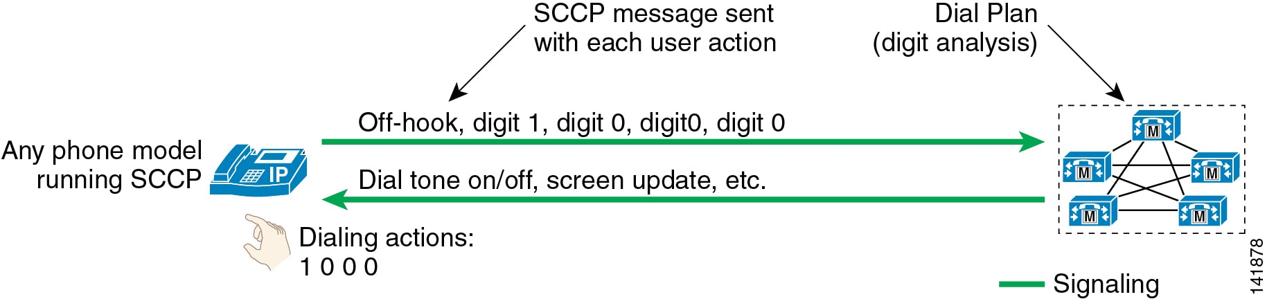
IP phones using SCCP report every single user input event to Unified CM immediately. For instance, as soon as the user goes off-hook, a signaling message is sent from the phone to the Unified CM server with which it is registered. The phone can be considered to be a terminal, where all decisions resulting from the user input are made by the Unified CM server's configured dial plan.
As other user events are detected by the phone, they are relayed to Unified CM individually. A user who goes off-hook and then dials 1000 would trigger five individual signaling events from the phone to Unified CM. All the resulting feedback provided to the user, such as screen messages, playing dial tone, secondary dial tone, ring back, reorder, and so forth, are commands issued by Unified CM to the phone in response to the dial plan configuration. (See Figure 10-1.)
Figure 10-1 User Input and Feedback for SCCP Phones
It is neither required nor possible to configure dial plan information on IP phones running SCCP. All dial plan functionality is contained in the Unified CM cluster, including the recognition of dialing patterns as user input is collected.
If the user dials a pattern that is denied by Unified CM, reorder tone is played to the user as soon as that pattern becomes the best match in Unified CM's digit analysis. For instance, if all calls to the pay-per-minute Numbering Plan Area (or area code) 976 are denied, reorder tone would be sent to the user's phone as soon as the user dials 91976.
User Input on Type-A SIP Phones
For purposes of this chapter only, we define Type-A phones to include the Cisco Unified IP Phone 7905, 7912, 7940, and 7960. Type-A phones differ somewhat from Type-B phones in their behavior, and Type-A phones do not offer support for Key Press Markup Language (KPML) as do Type-B phones. (See User Input on Type-B SIP Phones.)
Type-A IP phones using SIP offer two distinct modes of operation:
•
•
No SIP Dial Rules Configured on the Phone
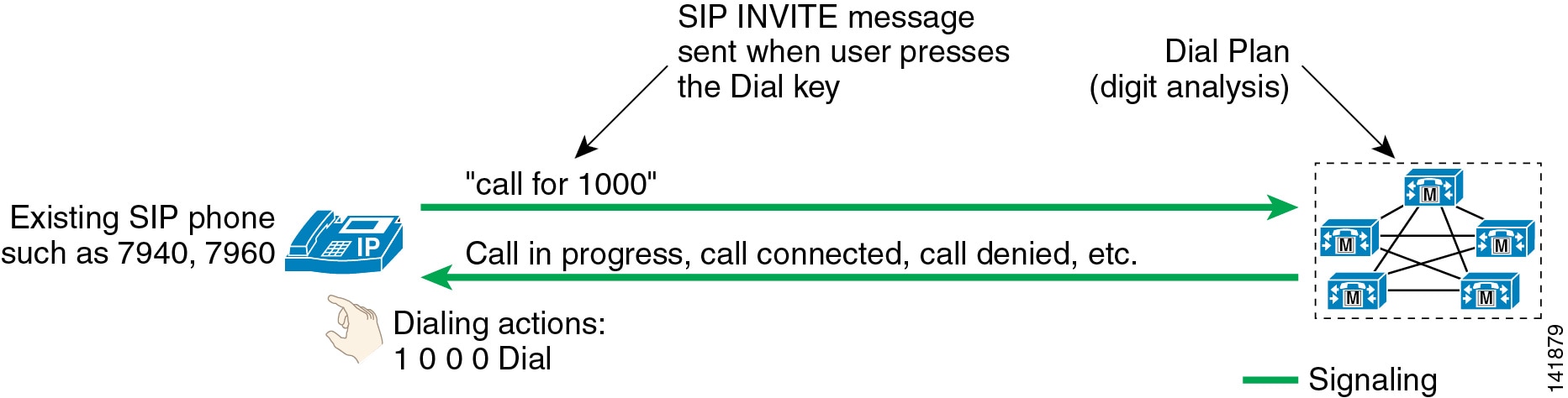
Figure 10-2 illustrates the behavior of a SIP Type-A phone with no dial plan rules configured on the phone. In this mode of operation, the phone accumulates all user input events until the user presses either the # key or the Dial softkey. This function is similar to the "send" button used on many mobile phones. For example, a user making a call to extension 1000 would have to press 1, 0, 0, and 0 followed by the Dial softkey or the # key. The phone would then send a SIP INVITE message to Unified CM to indicate that a call to extension 1000 is requested. As the call reaches Unified CM, it is subjected to the dial plan configuration for this phone, including all the class-of-service and call-routing logic implemented in Unified CM's dial plan.
Figure 10-2 User Input and Feedback for Type-A SIP Phones with No Dial Rules Configured
If the user dials digits but then does not press the Dial softkey or the # key, the phone will wait for inter-digit timeout (10 seconds by default) before sending a SIP INVITE message to Unified CM. For the example in Figure 10-2, dialing 1, 0, 0, 0 and waiting for inter-digit timeout would result in the phone placing a call to extension 1000 after ten seconds.
Note
If the user dials a pattern that is denied by Unified CM, the user must enter the entire pattern and press the Dial key, and the INVITE message must be sent to Unified CM, before any indication that the call is rejected (reorder tone) is sent to the caller. For instance, if all calls to NPA 976 are denied, the user would have to dial 919765551234 and press Dial before the reorder tone would be played.
SIP Dial Rules Configured on the Phone
SIP dial rules enable the phone to recognize patterns dialed by users. Once the recognition has occurred, the sending of the SIP INVITE message to Unified CM is automated and does not require the user to press the Dial key or wait for the inter-digit timeout. (For more details, see SIP Dial Rules.)
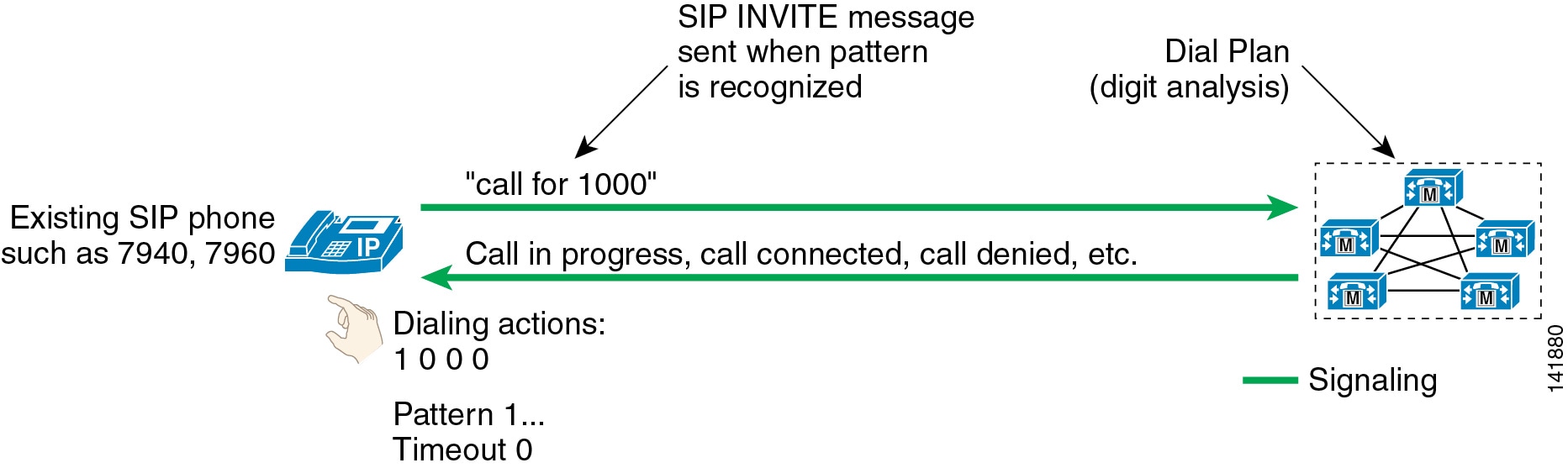
For example, if a branch location of the enterprise requires that calls between phones within the same branch be dialed as four-digit extensions, the phone could be configured to recognize the four-digit patterns so that the user is not required to press the Dial key or wait for the inter-digit timeout. (See Figure 10-3.)
Figure 10-3 User Input and Feedback for Type-A SIP Phones with Dial Rules Configured
In Figure 10-3, the phone is configured to recognize all four-digit patterns beginning with 1 and has an associated timeout value of 0. All user input actions matching the pattern will trigger the sending of the SIP INVITE message to Unified CM immediately, without requiring the user to press the Dial key.
Type-A phones using SIP dial rules offer a way to dial patterns not explicitly configured on the phone. If a dialed pattern does not match a SIP dial rule, the user can press the Dial key or wait for inter-digit timeout.
If a particular pattern is recognized by the phone but blocked by Unified CM, the user must dial the entire dial string before receiving an indication that the call is rejected by the system. For instance, if a SIP dial rule is configured on the phone to recognize calls dialed in the form 919765551234 but such calls are blocked by the Unified CM dial plan, the user will receive reorder tone at the end of dialing (after pressing the final 4 key).
User Input on Type-B SIP Phones
For purposes of this chapter only, we define Type-B phones to include the Cisco Unified IP Phone 7911, 7941, 7961, 7970, and 7971. Type-B phones differ somewhat from Type-A phones in their behavior, and Type-B phones offer support for Key Press Markup Language (KPML) but Type-A phones do not. (See User Input on Type-A SIP Phones.)
Type-B IP phones (such as the Cisco Unified IP Phone 7911, 7941, 7961, 7970, and 7971) running SIP offer two distinct modes of operation:
•
•
No SIP Dial Rules Configured on the Phone
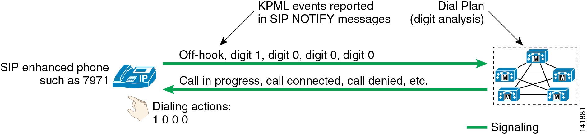
Type-B IP telephones offer functionality based on the Key Press Markup Language (KPML) to report user key presses. Each one of the user input events will generate its own KPML-based message to Unified CM. From the standpoint of relaying each user action immediately to Unified CM, this mode of operation is very similar to that of phones running SCCP. (See Figure 10-4.)
Figure 10-4 User Input and Feedback for Type-B SIP Phones with No Dial Rules Configured
Every user key press triggers a SIP NOTIFY message to Unified CM to report a KPML event corresponding to the key pressed by the user. This messaging enables Unified CM's digit analysis to recognize partial patterns as they are composed by the user and to provide the appropriate feedback, such as immediate reorder tone if an invalid number is being dialed.
In contrast to Type-A IP phones running SIP without dial rules, Type-B SIP phones have no Dial key to indicate the end of user input. In Figure 10-4, a user dialing 1000 would be provided call progress indication (either ringback tone or reorder tone) after dialing the last 0 and without having to press the Dial key. This behavior is consistent with the user interface on phones running the SCCP protocol.
SIP Dial Rules Configured on the Phone
Type-B IP phones can be configured with SIP dial rules so that dialed pattern recognition is accomplished by the phone. (See Figure 10-5.)
Figure 10-5 User Input and Feedback for Type-B SIP Phones with Dial Rules Configured
In Figure 10-5, the phone is configured to recognize all four-digit patterns beginning with 1, and it has an associated timeout value of 0. All user input actions matching these criteria will trigger the sending of a SIP INVITE message to Unified CM.
Note
Type-B phones using SIP dial rules offer only one way to dial patterns not explicitly configured on the phone. If a dialed pattern does not match a SIP dial rule, the user has to wait for inter-digit timeout before the SIP NOTIFY message is sent to Unified CM. Unlike Type-A IP phones, Type-B IP phones do not have a Dial key to indicate the end of dialing, except when on-hook dialing is used. In the latter case, the user can press the "dial" key at any time to trigger the sending of all dialed digits to Unified CM.
Note
If a particular pattern is recognized by the phone but blocked by Unified CM, the user must dial the entire dial string before receiving an indication that the call is rejected by the system. For instance, if a SIP dial rule is configured on the phone to recognize calls dialed in the form 919765551234 but such calls are blocked by the Unified CM dial plan, the user will receive reorder tone at the end of dialing (after pressing the 4 key).
SIP Dial Rules
Cisco Unified CM offers SIP dial rule functionality to allow phones to perform pattern recognition as user input is collected. For example, a phone can be configured to recognize the well established pattern 911 and to send a message to Unified CM to initiate an emergency call immediately, while at the same time allowing the user to enter patterns of variable length for international numbers.
It is important to note that pattern recognition configuration on the phone through the use of SIP dial rules does not supersede the Class of Service and Route Plan configurations of Unified CM. A phone might very well be configured to recognize long-distance patterns while Unified CM is configured to block such calls because the phone is assigned a class of service allowing only local calls.
There are two types of SIP dial rules, based on the phone model on which they will be deployed:
•
•
There are four basic Dial Parameters that can be used as part of a dial rule:
•
This parameter is the actual numerical representation of the pattern. It can contain digits, wildcards, or instructions to play secondary dial tone. The following table provides a list of values and their effect for the two types of dial rules.
•
This parameter specifies the button to which the dial pattern applies. If the user is initiating a call on line button 1, only the dial patterns specified for Button 1 apply. If this optional parameter is not configured, the dial pattern applies to all lines on the phone. This parameter applies only to the Cisco SIP IP Phone models 7940, 7941, 7960, 7961, 7970, and 7971. The button number corresponds to the order of the buttons on the side of the screen, from top to bottom, with 1 being on top button.
•
This parameter specifies the time, in seconds, before the system times out and dials the number as entered by the user. To have the number dialed immediately, specify 0. This parameter is available only for 7940_7960_OTHER dial rules. If this parameter is omitted, the phone's default inter-digit timeout value is used (default of 10 seconds).
•
This parameter represents the tag that automatically gets added to the dialed number. Valid values include IP (when SIP Call Agents other than Unified CM are deployed) and Phone. This parameter is available only for 7940_7960_OTHER dial rules. This parameter is optional, and it should be omitted in deployments where Unified CM is the only call agent.
Note
........
9.......Chooses first matching pattern: ........
Chooses longest matching pattern: 9.......
Call Routing in Unified CM
All dialing destinations configured in Unified CM are added to its internal call routing table as patterns. These destinations include IP phone lines, voicemail ports, route patterns, translation patterns, and CTI route points.
When a number is dialed, Unified CM uses closest-match logic to select which pattern to match from among all the patterns in its call routing table. In practice, when multiple potentially matching patterns are present, the destination pattern is chosen based on the following criteria:
•
•
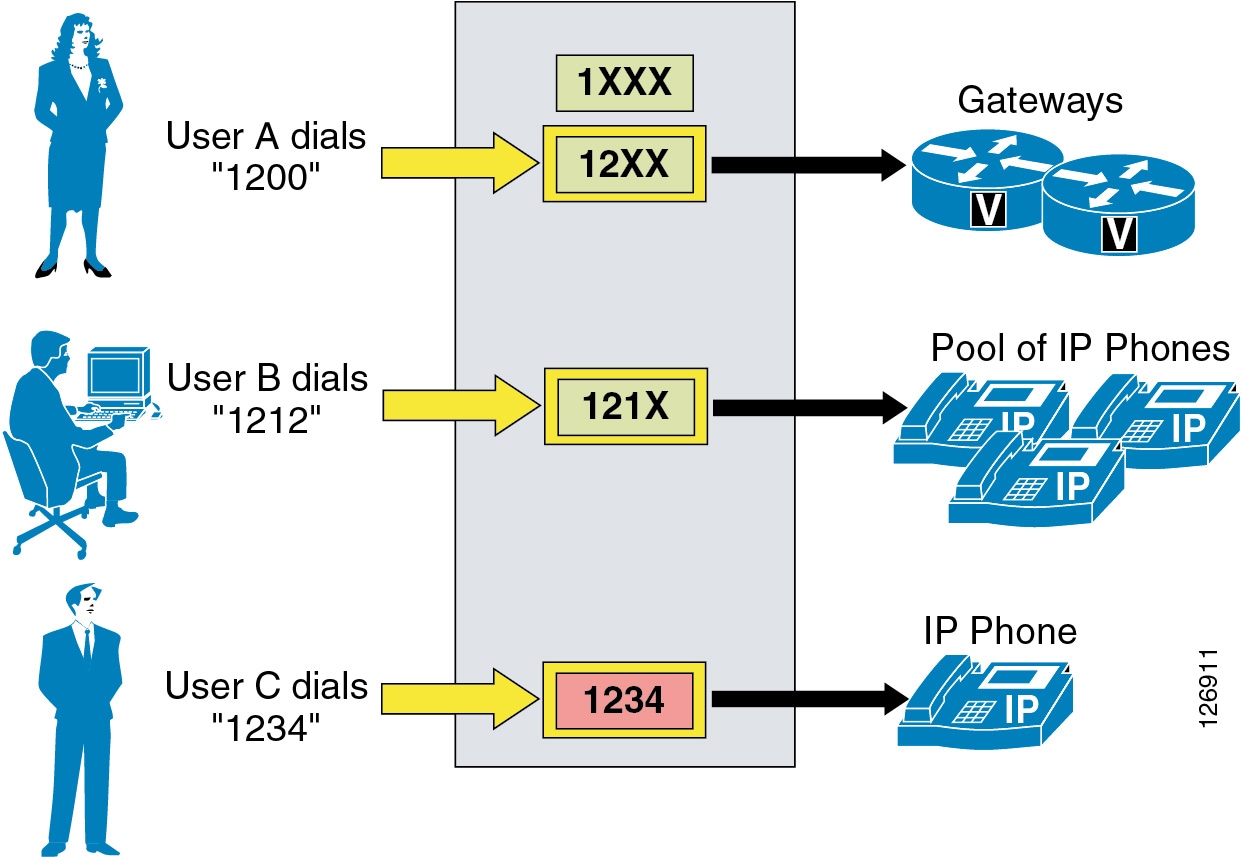
For example, consider the case shown in Figure 10-6, where the call routing table includes the patterns 1XXX, 12XX, and 1234.
Figure 10-6 Unified CM Call Routing Logic Example
When user A dials the string 1200, Unified CM compares it with the patterns in its call routing table. In this case, there are two potentially matching patterns, 1XXX and 12XX. Both of them match the dialed string, but 1XXX matches a total of 1000 strings (from 1000 to 1999) while 12XX matches only 100 strings (from 1200 to 1299). Therefore, 12XX is selected as the destination of this call.
When user B dials the string 1212, there are three potentially matching patterns, 1XXX, 12XX and 121X. As mentioned above, 1XXX matches 1000 strings and 12XX matches 100 strings. However, 121X matches only 10 strings; therefore it is selected as the destination of the call.
When user C dials the string 1234, there are three potentially matching patterns, 1XXX, 12XX, and 1234. As mentioned above, 1XXX matches 1000 strings and 12XX matches 100 strings. However, 1234 matches only a single string (the dialed string); therefore it is selected as the destination of this call.
Note
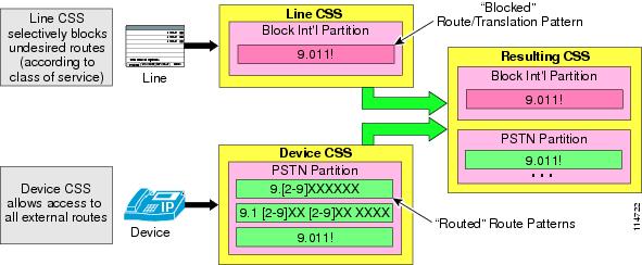
Unified CM automatically "knows" how to route calls to destinations within the same cluster. For external destinations such as PSTN gateways, H.323 gatekeepers, or other Unified CM clusters, you have to use the external route construct (described in the following sections) to configure explicit routing. This construct is based upon a three-tiered architecture that allows for multiple layers of call routing as well as digit manipulation. Unified CM searches for a configured route pattern that matches the external dialed string and uses it to select a corresponding route list, which is a prioritized list of the available paths for the call. These paths are known as route groups and are very similar to trunk groups in traditional PBX terminology. Figure 10-7 depicts the three-tiered architecture of the Unified CM external route construct.
Figure 10-7 External Route Pattern Architecture
The following sections describe the individual elements of the external route construct in Unified CM:
Route Patterns
Route patterns are strings of digits and wildcards, such as 9.[2-9]XXXXXX, configured in Unified CM to route calls to external entities. The route pattern can point directly to a gateway for routing calls or point to a route list, which in turn points to a route group and finally to a gateway.
Cisco strongly recommends that you use the complete route pattern, route list, and route group construct because it provides the greatest flexibility for call routing, digit manipulation, and future dial plan growth.
The @ Wildcard
•
•
http://www.cisco.com/en/US/products/sw/voicesw/ps5629/prod_maintenance_guides_list.html
•
Route Filters
•
•
•
•
International and Variable-Length Route Patterns
•
•
–
–
Overlap Sending and Overlap Receiving
In countries whose national numbering plan is not easily defined with static route patterns, you can configure Unified CM for overlap sending and overlap receiving.
Overlap sending means that Unified CM keeps collecting digits as they are dialed by the end users, and passes them on to the PSTN as they are dialed. To enable overlap sending in Unified CM Release 4.0 or later, check the Allow Overlap Sending box on the Route Pattern Configuration page. (In earlier Unified CM releases, overlap sending is enabled by setting the SendingCompleteIndicator service parameter to False.) The route pattern needs only to include the PSTN access code (for example, "9." in North America or "0." in many European countries).
Overlap receiving means that Unified CM receives the dialed digits one-by-one from a PRI PSTN gateway, and it then waits for completion of the dialed string before attempting to route the call to an internal destination. To enable overlap receiving in Cisco Unified CM Release 3.3(3) or later, set the OverlapReceivingFlagForPRI service parameter to True. (In earlier Unified CM releases, the parameter name was OverlapReceivingForPriFlag.)
Digit Manipulation in Route Patterns
•
•
•
•
Calling Line ID
•
•
Urgent Priority
•
•
For example, assume the route pattern 1XX is configured as urgent and the pattern 12! is configured as a regular route pattern. If a user dials 123, Unified CM will not make its routing decision as soon as it receives the third digit because even though 1XX is an urgent pattern, it is not the best match (10 total patterns matched by 12! versus 100 patterns matched by 1XX). Unified CM will have to wait for inter-digit timeout before routing the call because the pattern 12! allows for more digits to be input by the user.
Consider another example, where pattern 12[2-5] is marked as urgent and 12! is configured as a regular pattern. If the user dials 123, the pattern 12[2-5] is the best match (4 total patterns matched by 12[2-5] versus 10 patterns matched by 12!). Because the urgent-priority pattern is the best match, the T302 timer is aborted and no further user input is expected. Unified CM routes the call using pattern 12[2-5].
Call Classification
•
•
Forced Account Codes (FAC)
•
•
•
•
Client Matter Codes (CMC)
•
•
•
•
•
•
Route Lists
A route list is a prioritized list of eligible paths (route groups) for an outbound call. Typically, a route list is associated with a remote location, and multiple route patterns may point to it. A typical use of a route list is to specify two paths for a remote destination, where the first-choice path is across the IP WAN and the second-choice path is through the local PSTN gateways.
Route lists have the following characteristics:
•
•
•
•
•
1.
2.
3.
Route Groups
Route groups control and point to specific devices, which are typically gateways (MGCP or H.323), H.323 trunks to a gatekeeper or remote Unified CM cluster, or SIP trunks to a SIP proxy. (In Cisco Unified CM Release 3.2 and earlier, the role of the H.323 trunk was performed by the Anonymous Device gateway and by H.323 gateways configured using the Intercluster Trunk protocol.)
Unified CM sends calls to the devices according to the distribution algorithm assigned. Unified CM supports top-down and circular algorithms.
Route Group Devices
The route group devices are the endpoints accessed by route groups, and they typically consist of gateways or H.323 trunks to a gatekeeper or to remote Unified CMs. You can configure the following types of devices in Unified CM:
•
•
•
•
•
•
Note
Calling Privileges in Unified CM
Dialing privileges are configured in order to control which types of calls are allowed (or prevented) for a particular endpoint (such as phones, gateways, or CTI applications). All calls handled by Unified CM are subjected to the dialing privileges implemented through the configuration of the following elements:
A partition is a group of directory numbers (DNs) with similar accessibility, and a calling search space defines which partitions are accessible to a particular device. A device can call only those DNs located in the partitions that are part of its calling search space.
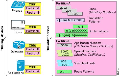
As illustrated in Figure 10-8, items that can be placed in partitions all have a dialable pattern, and they include phone lines, route patterns, translation patterns, CTI route group lines, CTI port lines, voicemail ports, and Meet-Me conference numbers. Conversely, items that have a calling search space are all devices capable of dialing a call, such as phones, phone lines, gateways, and applications (via their CTI route groups or voicemail ports).
Figure 10-8 Partitions and Calling Search Spaces
Partitions
The dial plan entries that you may place in a partition include IP phone directory numbers, translation patterns, route patterns, CTI route points, and voicemail ports. As described in the section on Call Routing in Unified CM, if two or more dial plan entries (directory numbers, route patterns, or so forth) overlap, Unified CM selects the entry with the closest match (most specific match) to the dialed number. In cases where two dial plan entries match the dialed pattern equally, Unified CM selects the dial plan entry that appears first in the calling search space of the device making the call.
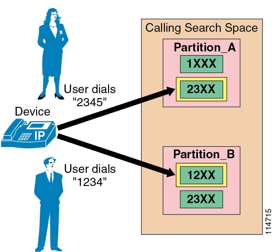
For example, consider Figure 10-9, where route patterns 1XXX and 23XX are part of Partition_A and route patterns 12XX and 23XX are part of Partition_B. The calling search space of the calling device lists the partitions in the order Partition_A:Partition_B. If the user of this device dials 2345, Unified CM selects route pattern 23XX in Partition_A as the matching entry because it appears first in the calling device's calling search space. However, if the user dials 1234, Unified CM selects route pattern 12XX in Partition_B as the matching entry because it is a closer match than 1XXX in Partition_A. Remember that the partition order in a calling search space is used exclusively as a tie-breaker in case of equal matches based on the closest-match logic.
Figure 10-9 Impact of Partition Order on the Matching Logic
Note
Beginning with Cisco Unified CM Release 4.1, partitions can be activated or deactivated based on the time and date. You can activate or deactivate partitions by first configuring time periods and schedules within Unified CM Administration and then assigning a specific time schedule to each partition. Outside of the times and days specified by the schedule, the partition is inactive, and all patterns contained within it are ignored by the Unified CM call routing engine. For more information on this feature, see Time-of-Day Routing.
Calling Search Spaces
A calling search space defines which partitions are accessible to a particular device. Devices that are assigned a certain calling search space can access only the partitions listed in that calling search space. Attempts to dial a DN in a partition outside that calling search space will fail, and the caller will hear a busy signal.
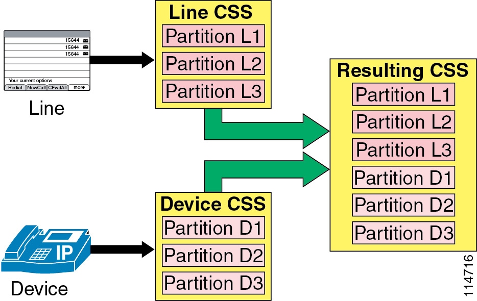
If you configure a calling search space both on an IP phone line and on the device (phone) itself, Unified CM concatenates the two calling search spaces and places the line's calling search space in front of the device's calling search space, as shown in Figure 10-10.
Figure 10-10 Concatenation of Line and Device Calling Search Spaces for IP Phones
If the same route pattern appears in two partitions, one contained in the line's calling search space and one contained in the device's calling search space, then according to the rules described in the section on Partitions, Unified CM selects the route pattern listed first in the concatenated list of partitions (in this case, the route pattern associated with the line's calling search space).
For recommendations on how to set the line and device calling search spaces, refer to the sections on Building Classes of Service for Unified CM with the Traditional Approach, and Building Classes of Service for Unified CM with the Line/Device Approach.
The maximum length of the combined calling search space (device plus line) is 1024 characters, including separator characters between each partition name. (For example, the string "partition_1:partition_2:partition_3" contains 35 characters.) Thus, the maximum number of partitions in a calling search space varies, depending on the length of the partition names. Also, because the calling search space clause combines the calling search space of the device and that of the line, the maximum character limit for an individual calling search space is 512 (half of the combined calling search space clause limit of 1024 characters).
Therefore, when you are creating partitions and calling search spaces, keep the names of partitions short relative to the number of partitions that you plan to include in a calling search space. For more details on configuring calling search spaces, refer to the Cisco Unified Communications Manager Administration Guide, available online at
Before you configure any partitions or calling search spaces, all DNs reside in a special partition named <None>, and all devices are assigned a calling search space also named <None>. When you create custom partitions and calling search spaces, any calling search space you create also contains the <None> partition, while the <None> calling search space contains only the <None> partition.
Note
Note
Call-Forward Calling Search Spaces
For Unified CM versions other than releases 5.x, while the main calling search space configured on the line is concatenated with the device calling search space, the calling search spaces configured for the three types of call forward (Forward All, Forward Busy, and Forward No Answer) are standalone values not concatenated with any other calling search space.
With Cisco Unified CM releases 5.x, the Call Forward All calling search space is concatenated with the Secondary Calling Search Space for Forward All available on the Directory Number configuration page, and the resulting calling search space applies to all calls when the Forward All action is initiated from the User page or from the Administrative pages.
These concatenated calling search spaces are also used when the Forward All action is invoked from a phone running SCCP or from an Type-B phone running SIP. For further details, see Building Classes of Service for Unified CM with the Line/Device Approach.
On Type-A IP phones running SIP, if Call Forward All is invoked from the phone itself, the device's Rerouting Calling Search Space is used for forwarded calls. If Forward All actions are invoked from the Unified CM User page or the Unified CM Administrative page, then any Forward All action initiated from the phone is irrelevant.
For example, assume an Type-A IP phone running SIP is configured with Forward All to extension 3000 from the Unified CM User page. At the same time, the phone itself is configured to Forward All to extension 2000. All calls made to that phone will be forwarded to extension 3000.
Note
When Forward All is initiated from an IP phone running SCCP or from an Type-B IP phone running SIP, user input is simultaneously compared to the patterns allowed in the configured Forward All calling search space(s). If an invalid destination pattern is configured, the user will be presented with reorder tone. When Forward All is invoked from an Type-A IP phone running SIP, Forward All user input is stored locally on the phone and is not verified against any calling search space in Unified CM. If user input corresponds to an invalid destination, no notification is offered to the user. Calls made to that phone will be presented with reorder tone as the phone tries to initiate a SIP re-route action to an invalid destination number.
When the Forward All calling search space is left as <None>, the results are difficult to predict and depend on the Unified CM release. Therefore, Cisco recommends the following best practices when configuring call-forward calling search spaces:
•
•
•
Digit Manipulation in Unified CM
The following tools provide digit manipulation capability in Unified CM:
•
•
The external route construct can be used to introduce some digit manipulation while routing calls to external devices, and it is described in the section on Call Routing in Unified CM.
Translation patterns are the most powerful tool in Unified CM to manipulate digits for any type of call. They follow the same general rules and use the same wildcards as route patterns. As with route patterns, you assign a translation pattern to a partition. However, when the dialed digits match the translation pattern, Unified CM does not route the call to an outside entity such as a gateway; instead, it performs the translation first and then routes the call again, this time using the calling search space configured within the translation pattern.
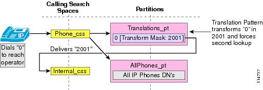
Translation patterns can be used for a variety of applications, as shown by the example in Figure 10-11.
Figure 10-11 Application Example for Translation Patterns
In this example, the administrator wishes to provide users with an operator service that is reached by dialing 0, while also maintaining a fixed-length internal numbering plan. The IP phones are configured with the Phone_css calling search space, which contains the Translations_pt partition (among others). A translation pattern 0 is defined in this partition, and the configured Called Party Transform Mask instructs Unified CM to replace the dialed string (0) with the new string 2001, which corresponds to the DN of the operator phone. A second lookup (of 2001 this time) is forced through the call routing engine, using the Internal_css calling search space, and the call can now be extended to the real operator DN of 2001, which resides in the AllPhones_pt partition.
Note
Automated Alternate Routing
The automated alternate routing (AAR) feature enables Unified CM to establish an alternate path for the voice media when the preferred path between two endpoints within the same cluster runs out of available bandwidth, as determined by the locations mechanism for call admission control.
The AAR feature applies primarily to centralized call processing deployments. For instance, if a phone in branch A calls a phone in branch B and the available bandwidth for the WAN link between the branches is insufficient (as computed by the locations mechanism), AAR can reroute the call through the PSTN. The audio path of the call would be IP-based from the calling phone to its local (branch A) PSTN gateway, TDM-based from that gateway through the PSTN to the branch B gateway, and IP-based from the branch B gateway to the destination IP phone.
AAR can be transparent to the users. You can configure AAR so that users dial only the on-net (for example, four-digit) directory number of the called phone and no additional user input is required to reach the destination through the alternate network (such as the PSTN).
Note
You must provide the following main elements for AAR to function properly:
•
•
•
Note
Establish the PSTN Number of the Destination
The rerouting of calls requires using a destination directory number (DN) that can be routed through the alternate network (for example, the PSTN). AAR uses the dialed digits to establish the on-cluster destination of the call and then combines them with the called party's External Phone Number Mask. The combination of these two elements must yield a fully qualified number that can be routed by the alternate network.
For example, assume phone A in San Francisco (DN = 2345) dials an on-net DN (1234) configured on phone B located in New York. If locations-based call admission control denies the call, AAR retrieves the External Phone Number Mask of the New York phone (212555XXXX) and uses it to derive the fully qualified number (2125551234) that can be routed on the PSTN.
The PSTN routing of a call from San Francisco to New York requires a "1" as a prefix to the phone number. Cisco recommends that you do not include this prefix as part of the External Phone Number Mask of phones because it would be displayed as part of the Calling Party Identification (CallerID) for any calls made by the phones to an off-net destination. Instead, Cisco recommends that you add the "1" as part of the AAR group configuration.
For deployments that cover multiple countries within the same Unified CM cluster, keep in mind that the external phone number mask needs to be configured in such a way that the destination phone can be reached from the same country or from a different country by simply prefixing digits. This means that any in-country prefixes (such as 0 in many countries) should not be included in the external phone number mask if they are not part of the E.164 address.
In order to better understand this, consider an example where a Unified CM cluster has a site in London (United Kingdom), one in Paris (France), and one in Nice (France). The E.164 address of the DID range in Paris is +33145678XXX, but these extensions are usually reached as 0145678XXX when calling from within the French PSTN.
When somebody in the London office wishes to dial the Paris office via the PSTN, the dialed string is 90033145678XXX. However, when somebody in the Nice office wishes to dial the Paris office via the PSTN, the dialed string is 00145678XXX. Therefore, in this case the external phone number mask for the Paris office phones must be set to 145678XXX and not to the usual French national number of 0145678XXX because, if the 0 were included in the mask, it would not be possible to obtain the string 90033145678XXX by simply prefixing additional digits.
Prefix the Required Access Codes
The destination number might require a prefix for an off-net access code (for example, 9) to be routed properly by the origination branch's dial plan. Furthermore, if the point of origin is located in a different area code (also known as Numbering Plan Area, or NPA), then a prefix of "1" might be required as part of the dialed string. When configuring AAR, you place the DNs in AAR groups. For each pair of AAR groups, you can then configure prefix digits to add to the DNs for calls between the two groups, including prefix digits for calls originating and terminating within the same AAR group.
As a general rule, place DNs in the same AAR group if they share all of the following characteristics:
•
•
•
For example, assume that both the San Francisco and New York sites share all of the preceding characteristics. We could place the DNs for San Francisco and New York into a single AAR group and configure the group such that AAR calls placed within this same AAR group are prefixed with 91. For phone A in San Francisco to reach phone B in New York (at 212 555 1234), the AAR group configuration prefixes 91 to the dialed string, yielding a completed string of 91 212 555 1234.
For deployments that cover multiple countries, you will typically need at least one AAR group per country. Considering the example introduced in the previous section, two AAR groups could be defined: the UK AAR group (assigned to all DNs in London) and the France AAR group (assigned to all DNs in Paris and Nice). The UK AAR group configuration prefixes 90033 for calls to the France AAR group, while the France AAR group simply prefixes 00 for calls within the same AAR group.
Select the Proper Dial Plan and Route
AAR calls should egress through a gateway within the same location as the calling phone, thus causing the completed dial string to be sent through the origination site's dial plan. To ensure that this is the case, select the appropriate AAR calling search space on the device configuration page in Unified CM Administration. Configure the off-net dial plan entries (for example, route patterns) in the AAR calling search space to point to co-located gateways and to remove the access code before presenting the call to the PSTN.
For example, phones at the San Francisco site can be configured with an AAR calling search space that permits long distance calls dialed as 91-NPA-NXX-XXXX but that delivers them to the San Francisco gateway with the access code (9) stripped.
Note
Note
Special Considerations for Sites Located Within the Same Local Dialing Area
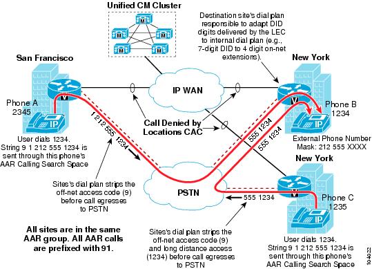
In some instances, the AAR dial string might have to be modified locally to allow for local area dialing. For example, assume two separate sites located in New York share the same area code of 212. (See Figure 10-12.) In this case, a number dialed as 91 212 555 1234 would have to be transformed to 9 555 1234.
This transformation is best done with a site-specific translation pattern of 91212.555XXXX (to strip the pre-dot digits and prepend 9). This translation pattern should be placed in a member partition of the AAR calling search space for the New York sites only; the San Francisco site still needs to reach this same destination as 91 212 555 1234. This translation pattern should also be placed in the New York sites' dial plan to provide proper routing of locally reachable numbers dialed as long distance calls. The New York sites' dial plan is responsible for accepting 9 555 1234 as a valid string and transforming it to 555 1234 before delivering the call to the PSTN.
Figure 10-12 Dialed Number Transformations for AAR Calls Between Sites
Note
Extension Mobility
The Extension Mobility feature enables a user to log in to an IP phone and automatically apply his or her profile to that phone, including extension number, speed dials, message waiting indicator (MWI) status, and calling privileges. This mechanism relies on the creation of a device profile associated with each Extension Mobility user. The device profile is effectively a virtual IP phone on which you can configure one or more lines and define calling privileges, speed dials, and so on.
When an IP phone is in the logged-out state, (that is, no Extension Mobility user has logged into it), the phone characteristics are determined by the device configuration page and the line configuration page(s). When a user logs in to an IP phone, the device configuration does not change, but the existing line configuration is saved in the Unified CM database and is replaced by the line configuration of the user's device profile.
One of the key benefits of Extension Mobility is that users can be reached at their own extensions regardless of where they are located, provided that they can log in to an IP phone controlled by the same Unified CM cluster. When Extension Mobility is applied to multisite deployments with centralized call processing, this capability is extended to multiple sites geographically separated from each other.
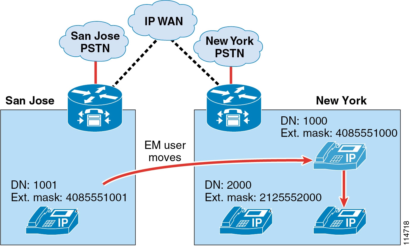
However, if you combine the Extension Mobility feature with the AAR feature described in the section on Automated Alternate Routing, some limitations exist. Consider the example shown in Figure 10-13, where Extension Mobility and AAR are deployed in a centralized call processing Unified CM cluster with one site in San Jose and one in New York.
Figure 10-13 Extension Mobility and AAR
In this example, assume that an Extension Mobility user who is normally based in San Jose has a DN of 1000 and a DID number of (408) 555-1000. That user's external phone number mask is therefore configured as 4085551000. The user now moves to the New York site and logs in. Also, assume that the IP WAN bandwidth between San Jose and New York has been entirely utilized.
When the user in San Jose with extension 1001 tries to call 1000, AAR is triggered and, based on the AAR calling search space of the calling party and the AAR group of the called party, a new call to 914085551000 is attempted by the San Jose phone. This call uses the San Jose gateway to access the PSTN, but because the DID (408) 555-1000 is owned by that same gateway, the PSTN sends the call back to it. The San Jose gateway tries to complete the call to the phone with extension 1000, which is now in New York. Because no bandwidth is available to New York, the AAR feature is invoked again, and one of the following two scenarios will occur:
•
•
Tip
This example highlights the fact that Extension Mobility leverages the dynamic aspect of Cisco IP Communications and, therefore, requires that the call routing between sites use the IP network. Because the E.164 numbers defined in the PSTN are static and the PSTN network is unaware of the movements of the Extension Mobility users, the AAR feature, which relies on the PSTN for call routing, cannot be used to reach Extension Mobility users who move to a site other than their home site.
Note
Immediate Divert (iDivert)
The Immediate Divert (iDivert) function is used to send calls directly to voicemail. It can be invoked when the call is ringing (incoming), when a call is on hold, or when a call is connected. For Cisco Unified CM releases prior to 5.1, the call is always sent to the invoking phone's voicemail box. Specifically, the iDivert action results in a call to the voicemail pilot of the invoking phone's voicemail profile, and it uses the calling search space configured on the voicemail pilot.
iDivert Enhancements in Cisco Unified CM 5.1
The iDivert function has been augmented in Cisco Unified CM 5.1 to allow incoming calls to be diverted to either the invoking phone's voicemail box (legacy behavior) or the voicemail box of the originally called party (enhanced behavior). The enhanced functionality is applicable only to diverted calls such as forwarded calls or calls redirected by an application.
For example:
Assume that phone A calls phone B, whose calls are forwarded to phone C. As phone C is ringing, the user at phone C activates the iDivert softkey, which offers two choices. The first choice results in the call being sent to the original called party's voicemail (in this case, phone B's voicemail box), while the second choice results in the call being sent to the iDivert invoker's voicemail (in this case, phone C's voicemail box). The same choices are available whether phone C invokes the feature while the call is ringing, connected, or placed on hold.
If a call is handled by Auto Call Pickup, Call Transfer, Call Park, Call Park Reversion, Conference, or a MeetMe Conference prior to the invocation of the iDivert function, the call is no longer considered to be a "diverted" call, and the only iDivert functionality available in this case is the legacy iDivert behavior (that is, sending the call to the invoker's voicemail). For example, assume phone A calls phone B, whose calls are forwarded to phone C, and then phone C transfers the call to phone D. This is not a diverted call because the last action applied to the call was the transfer to phone D. If phone D invokes the iDivert function, the call will be sent to phone D's voicemail box.
To enable the enhanced iDivert functionality, set the Unified CM service parameter Use Legacy Immediate Divert to False. When enabled, enhanced iDivert automatically allows the use of the feature over QSIG trunks, thus allowing an invoker's voicemail box to be hosted in a telephony system connected via QSIG.
In cases where iDivert is used in a cluster connected to other telephone systems using QSIG, there might be situations where only the legacy iDivert functionality (sending the call to the invoker's voicemail) is available to a phone when receiving a call. For instance, assume phones A and B are in cluster 1, and phone X is another QSIG-connected telephony system. Phone A calls phone X, which is call-forwarded to phone C. After the call is connected to phone C, iDivert will offer both the legacy (invoker's voicemail) and enhanced (original called party's voicemail) destinations only if QSIG path replacement has not occurred. If phone C invokes iDivert after QSIG path replacement, the only destination available is phone C's voicemail box.
Hunt Lists and Line Groups
The hunt pilot is typically used for call coverage, or distributing a call through a list of Skinny Client Control Protocol (SCCP) endpoints. For call distribution, you can use a hunt construct. This hunt construct is based upon a three-tiered architecture, similar to that used to route external calls, that allows for multiple layers of call routing as well as digit manipulation.
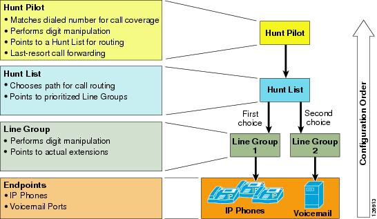
Unified CM searches for a configured hunt pilot that matches an incoming called number and uses it to select a corresponding hunt list, which is a prioritized list of the available paths for the call. These paths are known as line groups. Figure 10-14 depicts the three-tiered architecture of the hunt construct in Cisco Unified CM Release 4.1 or later.
Note
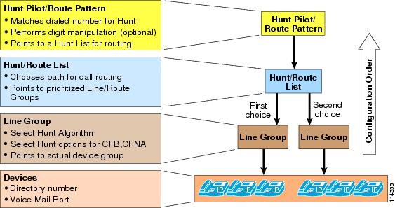
For comparison purposes, Figure 10-14 illustrates the hunt pilot architecture in Cisco Unified CM 4.1 and above, while Figure 10-15 shows the hunt pilot architecture in Unified CM 4.0.
Figure 10-14 Three-Tiered Architecture for the Hunt Construct in Unified CM Release 4.1
Figure 10-15 Hunt Construct in Unified CM Release 4.0
Hunt Pilot
Hunt pilots are strings of digits and wildcards similar to route patterns, such as 9.[2-9]XXXXXX, configured in Unified CM to route calls to directory numbers. The hunt pilot points directly to a hunt list. Hunt lists point to line groups, which finally point to SCCP endpoints.
Beginning with Cisco Unified CM Release 4.1, calls can be redirected to a final destination when the hunting fails because of one or both of the following reasons:
•
•
This call redirection is configured in the Hunt Forward Settings section of the Hunt Pilot configuration page, and the destination for this redirect can be either of the following options:
•
•
For example, you can implement the personal preferences option by configuring a user's phone so that the Forward No Answer field redirects the call to a hunt pilot, in order to search for someone else who can answer the call. If the call hunting fails, either because all the hunting options were exhausted or because a time-out period expired, the call can be sent to a destination personalized for the person who was originally called. For example, if you set the Forward No Coverage field within the person's DN configuration page to the voicemail number, the call will be sent to that person's voicemail box if hunting fails.
Note
The following considerations apply to calls handled by hunt pilots:
•
•
Note
•
Hunt List
A hunt list is a prioritized list of eligible paths (line groups) for call coverage. Hunt lists have the following characteristics:
•
•
•
•
Line Group
Line group members are user extension numbers that are controlled by Unified CM. Thus, when the call is being distributed through the line group members, Unified CM is in control of the call. Hunt options can be applied to the call when it is not answered or if the extension is busy or unregistered.
Line groups control the order in which the call is distributed, and they have the following characteristics:
•
•
•
•
–
–
–
–
•
–
–
–
–
For more information about hunt algorithms and hunt options, refer to the Cisco Unified Communications Manager Administration Guide, available at
Line Group Devices
The line group devices are the endpoints accessed by line groups, and they can be of any of the following types:
•
•
•
•
•
Time-of-Day Routing
Cisco Unified CM Release 4.1 introduces the time-of-day (ToD) routing feature. To use this feature, configure the following elements:
•
•
The time period allows you to configure start and end times for business hours. The start and end times indicate the times during which the calls can be routed. In addition to these times, you can set the event to repeat itself on a weekly or yearly basis. Moreover, you can also configure non-business hours by selecting "No business hours" from the Start Time and End Time options. All incoming calls will be blocked when this option is selected.
A time schedule is a group of specific time periods assigned to the partition. It determines whether the partition is active or inactive during the specified time periods. A matching/dialing pattern can be reached only if the partition in which the dialing pattern resides is active.
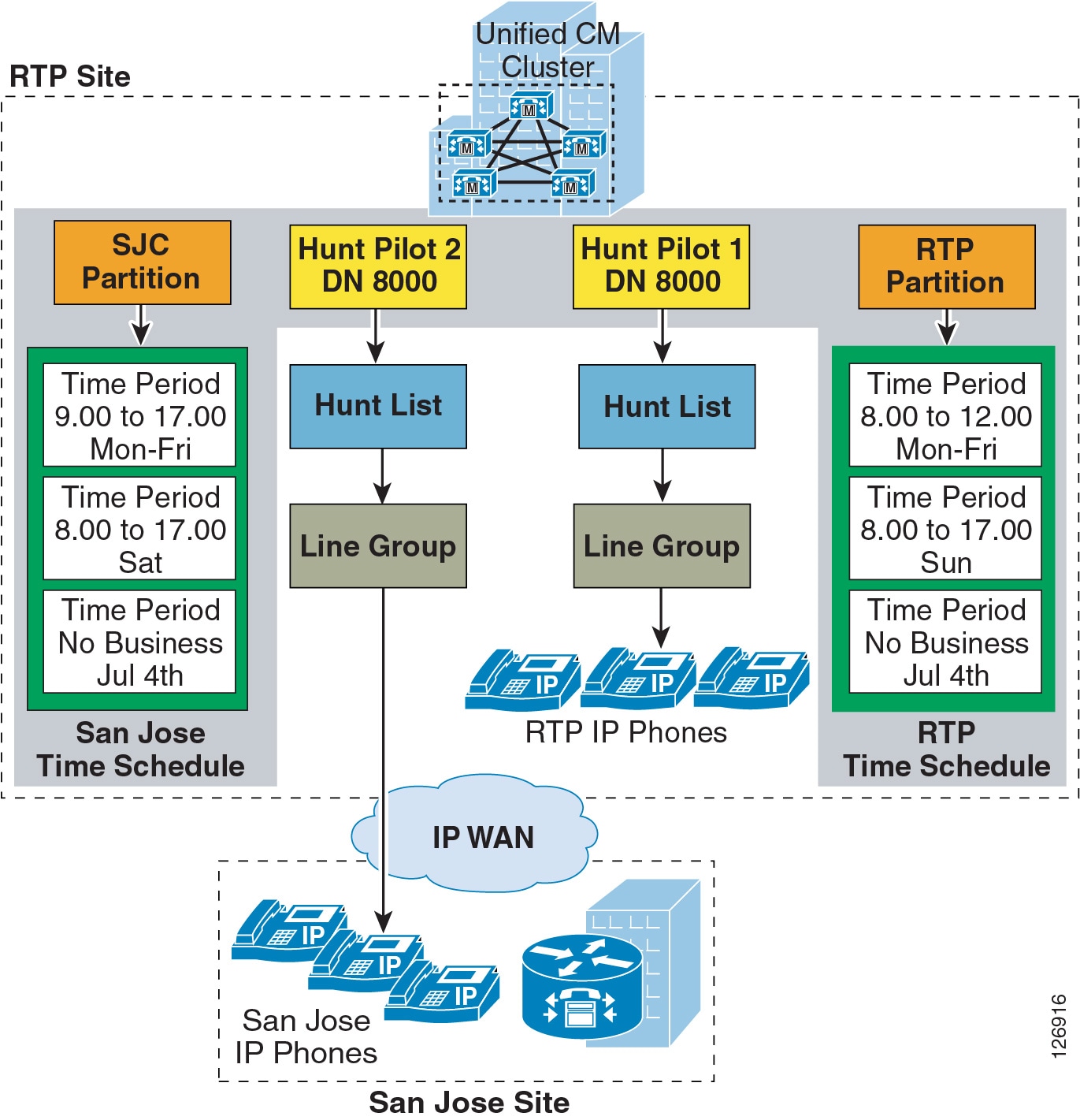
As illustrated in Figure 10-16, two hunt pilots with the same calling pattern (8000) are configured in two partitions (namely, RTP_Partition and SJC_Partition). Each of these partitions is assigned a time schedule, which contains a list of defined time periods. For example, RTP phones can be reached using Hunt Pilot 1 from 8:00 AM to 12:00 PM EST (GMT - 5.00) Monday through Friday as well as 8:00 AM to 5:00 PM on Sundays. In the same way, SJC phones can be reached using Hunt Pilot 2 from 8:00 AM to 5:00 PM PST (GMT - 8.00) Monday through Friday and 8:00 AM to 5:00 PM on Saturdays. Both of the hunt pilots in this example are inactive on July 4th.
Figure 10-16 Time-of-Day Routing
For the example in Figure 10-16, an incoming call to the hunt pilot (8000) on Wednesday at 3:00 PM will be forwarded to the SJC phones, while a person calling the hunt pilot on July 4th will get a fast busy tone unless there is another pattern that matches 8000.
Call Routing in Cisco IOS with H.323 Dial Peers
The call routing logic on Cisco IOS routers using the H.323 protocol relies on the dial peer construct. Dial peers are similar to static routes; they define where calls originate and terminate and what path the calls take through the network. Dial peers are used to identify call source and destination endpoints and to define the characteristics applied to each call leg in the call connection. Attributes within the dial peer determine which dialed digits the router collects and forwards to telephony devices.
For a detailed description of dial peers and their configuration, refer to Configuring Dial Plans, Dial Peers, and Digit Manipulation, part of the Cisco IOS Voice, Video, and Fax Configuration Guide, Release 12.2, available at
One of the keys to understanding call routing with dial peers is the concept of incoming versus outgoing call legs and, consequently, of incoming versus outgoing dial peers. Each call passing through the Cisco IOS router is considered to have two call legs, one entering the router and one exiting the router. The call leg entering the router is the incoming call leg, while the call leg exiting the router is the outgoing call leg.
Call legs can be of two main types:
•
•
For all calls going through the router, Cisco IOS associates one dial peer to each call leg. Dial peers are also of two main types, according to the type of call leg with which they are associated:
•
•
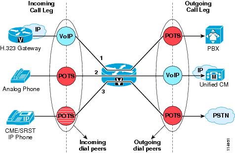
Figure 10-17 shows the following examples of different types of calls going through a Cisco IOS router:
•
•
•
Figure 10-17 Incoming and Outgoing Dial Peers
To match incoming call legs to incoming dial peers, the router selects a dial peer by matching the information elements in the setup message (called number/DNIS and calling number/ANI) with four configurable dial peer attributes. The router attempts to match these items in the following order:
1.
2.
3.
4.
The router must match only one of these conditions. It is not necessary for all the attributes to be configured in the dial peer or that every attribute match the call setup information; only one condition must be met for the router to select a dial peer. The router stops searching as soon as one dial peer is matched, and the call is routed according to the configured dial peer attributes. Even if there are other dial peers that would match, only the first match is used.
How the router selects an outbound dial peer depends on whether direct-inward-dial (DID) is configured in the inbound POTS dial peer:
•
•
By default, dial peers in a hunt group are selected according to the following criteria, in the order listed:
1.
This method selects the destination pattern that matches the greatest number of dialed digits. For example, if one dial peer is configured with a dial string of 345.... and a second dial peer is configured with 3456789, the router would first select 3456789 because it has the longest explicit match of the two dial peers.
2.
This method uses the priority configured with the preference dial peer command. The lower the preference number, the higher the priority. The highest priority is given to the dial peer with preference order 0. If the same preference is defined in multiple dial peers with the same destination pattern, a dial peer is selected randomly.
3.
In this method, all destination patterns are weighted equally.
You can change this default selection order or choose different methods for hunting dial peers by using the dial-peer hunt global configuration command. An additional selection criterion is least recent use, which selects the destination pattern that has waited the longest since being selected (equivalent to longest idle for Unified CM line groups).
Observe the following best practices when configuring H.323 dial peers on a Cisco IOS router:
•
dial-peer voice 999 potsincoming called-number .direct-inward-dialport 1/0:23•
dial-peer voice 100 voippreference 1!--- Make this the first choice dial peer.ip precedence 5destination-pattern 1...session target ipv4:10.10.10.2!--- This is the address of the primary Unified CM.dtmf-relay h245-alphadial-peer voice 101 voippreference 2!--- This is the second choice.ip precedence 5destination-pattern 1...session target ipv4:10.10.10.3!--- This is the address of the secondary Unified CM.dtmf-relay h245-alphaCall Routing in Cisco IOS with a Gatekeeper
An H.323 gatekeeper is an optional node that manages endpoints (such as H.323 terminals, gateways, and Multipoint Control Units (MCUs), as well as Cisco Unified Communications Manager Express (Unified CME) and Unified CM clusters) in an H.323 network, providing them with call routing and call admission control functions. The endpoints communicate with the gatekeeper using the H.323 Registration Admission Status (RAS) protocol.
Endpoints attempt to register with a gatekeeper on startup. When they want to communicate with another endpoint, they request admission to initiate a call using a symbolic alias for the endpoint, such as an E.164 address or an email address. If the gatekeeper decides that the call can proceed, it returns a destination IP address to the originating endpoint. This IP address might not be the actual address of the destination endpoint, but instead it might be an intermediate address, such as the address of an IP-to-IP gateway or a gatekeeper that routes call signaling.
For more details about the H.323 protocol and the message exchange between H.323 endpoints and gatekeepers, refer to the Cisco IOS H.323 Configuration Guide, available at
The Cisco 2600, 3600, 3700, 2800, 3800, and 7200 Series routers all support the gatekeeper feature. You can configure Cisco IOS gatekeepers in a number of different ways for redundancy, load balancing, and hierarchical call routing. This section focuses on the call routing capabilities of the gatekeeper feature. For redundancy and scalability considerations, refer to Gatekeeper Redundancy; for call admission control considerations, refer to Cisco IOS Gatekeeper Zones.
Call routing in Cisco IOS gatekeeper is based on the following types of information:
•
•
•
A zone is a collection of H.323 devices (such as endpoints, gateways, or MCUs) that register with a gatekeeper. There can be only one active gatekeeper per zone, and you can define up to 100 local zones on a single gatekeeper.
When an H.323 endpoint registers with the gatekeeper, it is assigned to a zone and it can optionally register one or more E.164 addresses for which it is responsible, as well as a technology prefix that specifies which kinds of calls it can handle (for example, voice, video, fax, and so on).
For each zone, you can configure one or more zone prefixes on the gatekeeper. Zone prefixes are strings that contain digits and wildcards and are used by the gatekeeper to facilitate call routing decisions. The following characters are allowed in a zone prefix string:
•
•
•
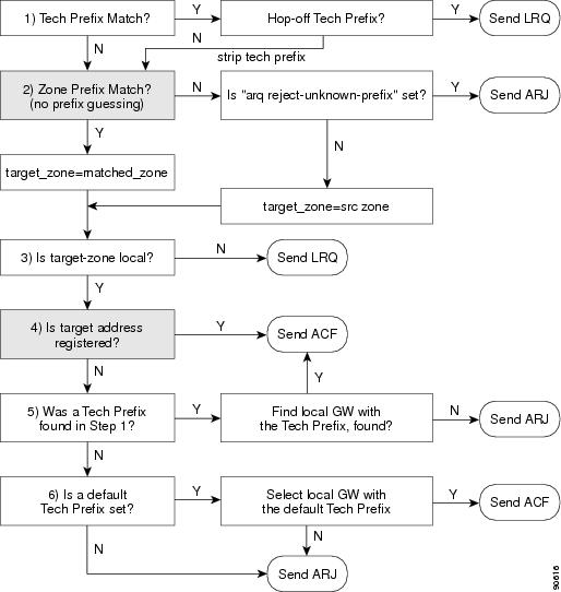
To understand the gatekeeper call routing behavior, it is helpful to consider the message parsing logic. Figure 10-18 illustrates the parsing logic for an Admission Request (ARQ). To initiate a call, an endpoint sends an Admission Request (ARQ) to the gatekeeper. The ARQ contains either an H.323 ID or the E.164 address of the destination, or called party, as well as the E.164 address or H.323 ID of the source, or calling party.
If the ARQ contains the E.164 address (with Unified CM, the ARQ always contains an E.164 address), the ARQ may or may not contain a technology prefix. If the ARQ contains a technology prefix, the gatekeeper strips it from the called number. If the ARQ does not contain a technology prefix, the gatekeeper uses the default technology prefix if one is configured (see the gw-type-prefix command in the section on Centralized Gatekeeper Configuration). The technology prefix thus obtained is stored in memory, and the gatekeeper continues with the call routing algorithm.
Next, the gatekeeper tries to match the called number with one of the configured zone prefixes. Longest-match is used if multiple potential matches exist. If no zone prefix can be matched, and if the gatekeeper is configured to accept calls with an unknown prefix, the gatekeeper then assumes that the destination zone is equal to the source zone.
At this point, the gatekeeper searches in the chosen destination zone for a registered E.164 address that matches the called number. If there is a match, the gatekeeper can send an Admission Confirm (ACF), provided that the requested bandwidth for the call is available and that the called endpoint is registered with the gatekeeper. The ACF will contain the IP address of the destination endpoint. If the bandwidth is unavailable or the called endpoint is not registered, the gatekeeper returns an Admission Reject (ARJ) to the calling endpoint.
If there is no matching E.164 address registered in the destination zone, the gatekeeper will use the previously stored technology prefix to choose a gateway registered in that zone as the destination for the call. The same considerations regarding bandwidth availability and endpoint registration dictate whether the gatekeeper will send an ACF or an ARJ to the calling endpoint.
Upon receipt of an ACF from the gatekeeper, the source endpoint can send a setup message directly to the destination endpoint by using the IP address returned in the ACF.
Figure 10-18 Gatekeeper Address Resolution for an ARQ
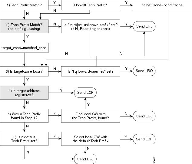
Figure 10-19 illustrates the parsing logic for a Location Request (LRQ). LRQ messages are exchanged between gatekeepers and are used for inter-zone (remote zone) calls. For example, gatekeeper A receives an ARQ from a local zone gateway requesting call admission for a remote zone device. Gatekeeper A then sends an LRQ message to gatekeeper B. Gatekeeper B replies to the LRQ message with either a Location Confirm (LCF) or Location Reject (LRJ) message, depending on whether it is configured to admit or reject the inter-zone call request and whether the requested resource is registered.
Figure 10-19 Gatekeeper Address Resolution for an LRQ
Traditional Cisco IOS gatekeeper functionality has been extended to accommodate for IP-to-IP gateways through the concept of a via-zone gatekeeper. (Refer to Cisco IOS Gatekeeper and IP-to-IP Gateway with RSVP, for some deployment examples.)
A via-zone gatekeeper differs from legacy gatekeepers in how it uses LRQ and ARQ messages for call routing. Using via-zone gatekeepers will maintain normal clusters and functionality. Legacy gatekeepers examine incoming LRQs based on the called number, and more specifically the dialedDigits field in the destinationInfo portion of the LRQ. Via-zone gatekeepers look at the origination point of the LRQ before looking at the called number. If an LRQ comes from a gatekeeper listed in the via-zone gatekeeper's remote zone configurations, the gatekeeper checks to see that the zone remote configuration contains an invia or outvia keyword. If the configuration contains either of these keywords, the gatekeeper uses the new via-zone behavior; if not, it uses legacy behavior.
For ARQ messages, the gatekeeper determines if an outvia keyword is configured on the destination zone. If the outvia keyword is configured and the zone named with the outvia keyword is local to the gatekeeper, the call is directed to an IP-IP gateway in that zone by returning an ACF pointing to the IP-IP gateway. If the zone named with the outvia keyword is remote, the gatekeeper sends a location request to the outvia gatekeeper rather than the remote zone gatekeeper. The invia keyword is not used in processing the ARQ.
Centralized Gatekeeper Configuration
A single gatekeeper can support call routing between clusters and call admission control for up to 100 Unified CM clusters. Figure 10-20 illustrates a distributed call processing environment with two Unified CM clusters and a single, centralized gatekeeper.
Figure 10-20 Centralized Gatekeeper Supporting Two Clusters
Example 10-1 shows the gatekeeper configuration for the example in Figure 10-20.
Example 10-1 Configuration for Centralized Gatekeeper
gatekeeperzone local GK-Site1 customer.com 10.1.10.100zone local GK-Site2 customer.comzone prefix GK-Site1 408.......zone prefix GK-Site2 212.......bandwidth interzone GK-Site1 160bandwidth interzone GK-Site2 160gw-type-prefix 1#* default-technologyarq reject-unknown-prefixno shutdownThe following notes also apply to Figure 10-20:
•
•
•
•
Technology prefixes indicate the type of call being made. The specific values used as technology prefixes are arbitrary and are defined by the network administrator. The same values should be used consistently throughout the entire deployment.
Technology prefixes are sent as a prefix to the E.164 address (phone number) to indicate whether the call is voice, video, or some other type. The # symbol is generally used to separate the prefix from the E.164 number. If a prefix is not included, the default technology prefix is used to route the call. There can be only one default technology prefix for the entire deployment.
Cisco IOS gateways automatically add a technology prefix to outbound calls if the gateway has a prefix configured. The gateway also automatically strips the prefix from incoming H.323 calls. Unified CM can register with the gatekeeper using a technology prefix, as specified on the configuration page for gatekeeper-controlled H.323 trunks. However, this technology prefix is not automatically added to outgoing calls to the gatekeeper, and is not automatically stripped from inbound calls to Unified CM. You can use translation patterns and significant digits to manipulate the called number so as to add or strip the technology prefix as needed.
•
Distributed Gatekeeper Configuration
Gatekeepers can be distributed to conserve bandwidth or to provide local call routing for H.323 gateways in case of a WAN failure. Figure 10-21 illustrates a distributed call processing environment with two clusters and two gatekeepers.
Figure 10-21 Distributed Gatekeepers Supporting Two Clusters
Example 10-2 shows the gatekeeper configuration for Site 1 in Figure 10-21.
Example 10-2 Gatekeeper Configuration for Site 1
gatekeeperzone local GK-Site1 customer.com 10.1.10.100zone remote GK-Site2 customer.com 10.1.11.100zone prefix GK-Site1 408.......zone prefix GK-Site2 212.......bandwidth remote 160gw-type-prefix 1#* default-technologyarq reject-unknown-prefixno shutdownThe following notes apply to Example 10-2:
•
•
•
•
•
•
Example 10-3 shows the gatekeeper configuration for Site 2 in Figure 10-21.
Example 10-3 Gatekeeper Configuration for Site 2
gatekeeperzone local GK-Site2 customer.com 10.1.11.100zone remote GK-Site1 customer.com 10.1.10.100zone prefix GK-Site2 212.......zone prefix GK-Site1 408.......bandwidth remote 160gw-type-prefix 1#* default-technologyarq reject-unknown-prefixno shutdownThe following notes apply to Example 10-3:
•
•
•
•
•
•
Distributed Gatekeeper Configuration with Directory Gatekeeper
Because there is no gatekeeper protocol available to update gatekeeper routing tables, use of a directory gatekeeper can help make distributed gatekeeper configurations more scalable and more manageable. Implementing a directory gatekeeper makes gatekeeper configurations at each site simpler and moves most of the configuration for inter-zone communication into the directory gatekeeper.
Without a directory gatekeeper, you would have to add an entry in every gatekeeper on the network every time you add a new zone on one of the gatekeepers. However, with a directory gatekeeper, you can add the new zone in the local gatekeeper and the directory gatekeeper only. If the local gatekeeper cannot resolve a call request locally, it forwards that request to the directory gatekeeper with a matching zone prefix.
Figure 10-22 illustrates a Unified CM distributed call processing environment with distributed gatekeepers for local call routing and a directory gatekeeper to provide call routing between gatekeepers.
Figure 10-22 Distributed Gatekeepers with a Directory Gatekeeper
Example 10-4 shows the gatekeeper configuration for Site 1 in Figure 10-22. Because the Site 1 and Site 2 gatekeeper configurations are almost identical in this example, only Site 1 is covered here.
Example 10-4 Gatekeeper Configuration for Site 1, with Directory Gatekeeper
gatekeeperzone local GK-Site1 customer.com 10.1.10.100zone remote DGK customer.com 10.1.10.101zone prefix GK-Site1 408.......zone prefix DGK ..........bandwidth remote 160gw-type-prefix 1#* default-technologyarq reject-unknown-prefixno shutdownThe following notes also apply to Example 10-4:
•
•
•
•
•
•
•
Example 10-5 shows the directory gatekeeper configuration for the example in Figure 10-22.
Example 10-5 Directory Gatekeeper Configuration
gatekeeperzone local DGK customer.com 10.1.10.101zone remote GK-Site1 customer.com 10.1.10.100zone remote GK-Site2 customer.com 10.1.11.100zone prefix GK-Site1 408*zone prefix GK-Site2 212*lrq forward-queriesno shutdownThe following notes also apply to Example 10-5:
•
•
•
•
Calling Privileges in Cisco IOS with H.323 Dial Peers
Use the class of restriction (COR) functionality to implement calling privileges with Cisco IOS-based systems using H.323, including H.323 gateways, SRST, and Cisco Unified Communications Manager Express (Unified CME). This functionality provides flexibility in network design, allows administrators to block calls for all users (for example, calls to 900 numbers), and applies different calling privileges to call attempts from different originators (for example, it allows some users but not others to call international numbers).
The fundamental mechanism at the center of the COR functionality relies on the definition of incoming and outgoing corlists that are associated to existing dial peers, where the concepts of incoming and outgoing are relative to the Cisco IOS router (as in the case of dial peers). Each corlist is defined to include a number of members, which are simply tags previously defined within Cisco IOS.
When a call goes through the router, an incoming dial peer and an outgoing dial peer are selected based on the Cisco IOS dial peer routing logic. If corlists are associated with the selected dial peers, the following additional check is performed before extending the call:
•
•
If no corlist statements are applied to some dial peers, the following properties apply:
•
•
This behavior is best illustrated with an example as shown in Figure 10-23, where one VoIP dial-peer and two POTS dial-peer are defined.
Figure 10-23 Example of COR Behavior
The VoIP dial-peer is associated with the c1 incoming corlist, with members A, B, and C. You can think of members of the incoming corlist as "keys."
The first POTS dial-peer has a destination-pattern of 1.. and is associated with the c2 outgoing corlist, with members A and B. The second POTS dial-peer has a destination-pattern of 2.. and is associated with the c3 outgoing corlist, with members A, B, and D. You can think of members of the outgoing corlists as "locks."
For the call to succeed, the incoming corlist of the incoming dial-peer must have all the "keys" needed to open all the "locks" of the outgoing corlist of the outgoing dial-peer.
In the example shown in Figure 10-23, a first VoIP call with destination 100 is received by the router. The Cisco IOS call routing logic matches the incoming call leg with the VoIP dial-peer and the outgoing call leg with the first POTS dial-peer. The COR logic is then applied; because the c1 incoming corlist has all the keys needed for the c2 outgoing corlist locks (A and B), the call succeeds.
A second VoIP call with destination 200 is then received by the router. The Cisco IOS call routing logic matches the incoming call leg with the VoIP dial-peer and the outgoing call leg with the second POTS dial-peer. The COR logic is then applied; because the c1 incoming corlist is missing one "key" for the c3 outgoing corlist (D), the call is rejected.
Follow these steps when configuring the COR functionality in Cisco IOS:
Step 1
Step 2
Step 3
With Cisco IOS Release 12.2(8)T and later, you can apply the COR functionality to SRST-controlled IP phones. Because IP phones register with the SRST router dynamically, SRST has no prior knowledge of the individual phones until they lose connectivity to the Unified CM cluster. Therefore, the COR feature configuration for SRST is based on the phone DNs instead. When the IP phones register with the SRST router, they communicate their DN to it, thus allowing the SRST router to assign them to the appropriate corlist.
Configure COR for IP phones controlled by SRST by using the command cor {incoming | outgoing} corlist-name {corlist-number starting-number - ending-number | default} within the call-manager-fallback configuration mode.
The following limitations apply to this command:
•
•
The COR functionality can also be deployed with Cisco Unified Communications Manager Express (Unified CME), using Cisco IOS Release 12.2(8)T and later. Because the individual IP phones are specifically configured within Unified CME, you can apply corlists directly to the IP phones themselves by using the command cor {incoming | outgoing} corlist-name within the ephone-dn dn-tag configuration mode of each IP phone.
Refer to the section on Building Classes of Service in Cisco IOS with H.323, for an example of how to apply all these concepts in practice.
For more details on configuration of Cisco SRST and Unified CME, refer to the Cisco SRST System Administrator Guide and the Cisco Unified Communications Manager Express System Administrator Guide, both available at
Digit Manipulation in Cisco IOS with H.323 Dial Peers
In Cisco IOS routers running H.323, digit manipulation is performed via voice translation profiles, which are used to manipulate the calling number (ANI) or called number (DNIS) digits for a voice call or to change the numbering type of a call.
Voice translation profiles are available starting with Cisco IOS Release 12.2(11)T, and they are used to convert a telephone number into a different number before the call is matched to an incoming dial peer or before the call is forwarded by the outgoing dial peer. For example, within your company you might dial a five-digit extension to reach an employee at another site. If the call is routed through the PSTN to reach the other site, the originating gateway must use voice translation profiles to convert the five-digit extension into the ten-digit format that is recognized by the central office switch.
You configure voice translation profiles by using the voice translation-rule and voice translation-profile Cisco IOS commands, which use regular expressions to define the digit strings to be modified. You then specify if the manipulations should be associated to calling numbers, called numbers, or redirected called numbers. After you define a voice translation profile, you can apply it to any of the following elements:
•
•
•
•
•
Note
A typical application of voice translation profiles is to enable the preservation of on-net inter-site dialing habits from a branch site even when the IP WAN is unavailable and the router is running in SRST mode. For example, consider a simple deployment with a central site in San Jose and three remote sites in San Francisco, New York, and Dallas. Table 10-4 shows the DID ranges and the internal site codes for this example.
Inter-site calls are normally placed across the IP WAN by dialing the on-net access code 8 followed by the one-digit site code and the four-digit extension of the called party. To preserve these dialing habits even when the IP WAN is down and Cisco SRST is active, the internal numbers must be converted back into the E.164 numbers before being sent to the PSTN. A sample configuration for the San Francisco router is as follows:
voice translation-rule 1rule 1 /^81/ /91408555/rule 2 /^83/ /91212555/rule 3 /^84/ /91972555/voice translation-profile on-net-xlatetranslate called 1call-manager-fallbacktranslation-profile outgoing on-net-xlatedial-peer voice 2 potsdestination-pattern 91[2-9]..[2-9]......port 1/0:0direct-inward-dialforward-digits 11With this configuration, when the San Francisco site is in SRST mode and a user dials 831000, the router will match rule 2 of voice translation-rule 1 and translate the called number to 912125551000. This new number will then be used to match the outgoing dial peer (dial-peer voice 2).
For a detailed description of dial peers and their configuration, refer to Configuring Dial Plans, Dial Peers, and Digit Manipulation, part of the Cisco IOS Voice, Video, and Fax Configuration Guide, Release 12.2, available at
For a thorough explanation of regular expression syntax in Cisco IOS, refer to the document on Regular Expressions, available at
Design Considerations
This section presents the following dial plan design considerations for multisite deployments:
•
•
•
•
–
–
–
•
–
–
•
•
Design Guidelines for Multisite Deployments
The following guidelines and best practices apply in common to all multisite IP Telephony deployments. For deployments that involve more than one Unified CM cluster, also refer to the section on Additional Considerations for Distributed Call Processing Deployments.
•
•
•
•
•
–
–
The second approach is preferable because it does not require additional calling search spaces to be defined for AAR. The additional * route patterns also provide a good troubleshooting and testing tool that allows for overriding the "force on-net" configuration and placing calls over the PSTN even when AAR is not invoked, or to force a call through the PSTN when the destination number is located in a branch under SRST mode.
•
–
This method involves configuring a set of N route patterns in a global partition, with each pattern pointing to a route list that has the appropriate remote site route group as the first choice and the central site route group as the second choice.
–
This method involves configuring N sets of N route patterns in site-specific partitions, with each pattern pointing to a route list that has the appropriate remote site route group as the first choice and the local site route group as the second choice.
While the second approach allows for an optimal failover scenario when the remote gateway or the IP WAN is unavailable, it also introduces a high level of complexity into the dial plan because it requires a minimum of N2 route patterns and N2 route lists, as opposed to the N route patterns and N route lists needed with the first approach.
•
•
Note
Additional Considerations for Distributed Call Processing Deployments
In addition to the considerations made in the previous section, observe the following best practices when designing a dial plan for a distributed call processing deployment (that is, any multisite deployment involving multiple Unified CM clusters):
•
•
•
•
•
•
•
–
–
–
For details on how to configure a Cisco IOS gatekeeper for distributed call processing deployments, see Gatekeeper Design Considerations.
Choosing a Dial Plan Approach
As introduced in Planning Considerations, there are two main approaches to a dial plan for internal destinations within an IP Telephony system:
•
•
To help you decide which approach is best suited for your needs, consider the following high-level design questions:
•
•
•
•
•
•
•
Uniform on-net dial plans are the easiest to design and configure; however, they work best for small to medium deployments, and they become impractical when the number of sites and users increases. They are described and analyzed in detail in the section on Deploying Uniform On-Net Dial Plans.
Variable-length on-net dial plans are more scalable but also more complex to design and configure. Figure 10-24 shows the typical requirements for a large-scale deployment using the variable-length on-net dial plan approach.
Figure 10-24 Typical Dialing Requirements for Large Multisite Deployments
With Unified CM, there are two main methods for implementing a variable-length on-net dial plan:
•
The internal extensions are placed in different partitions according to the site where they are located. This method is typically based on full E.164 addresses for inter-site calls and is analyzed in detail in the section on Deploying Variable-Length On-Net Dial Plans with Partitioned Addressing.
•
All internal extensions are placed in the same partition. This method is typically based on on-net site codes for inter-site calls and is analyzed in detail in the section on Deploying Variable-Length On-Net Dial Plans with Flat Addressing. In some cases it is possible to use this approach even when using full E.164 addresses for inter-site calls, as described in the section on Special Considerations for Deployments Without Site Codes.
Deploying Uniform On-Net Dial Plans
You can implement a uniform on-net dial plan by following these guidelines:
•
•
•
Figure 10-25 shows an example implementation for a single Unified CM cluster deployment.
Figure 10-25 Example of Uniform On-Net Dial Plan Deployment
Use this approach if both of the following conditions apply:
•
•
The following sections analyze implementation details and best practices for different types of calls within the framework of uniform on-net dial plans:
•
•
Inter-Site Calls Within a Cluster
Because all internal DNs are directly reachable from every device's calling search space, all on-net calls (intra-site and inter-site) are automatically enabled and need no additional configuration within Unified CM.
Outgoing PSTN and IP WAN Calls
PSTN calls are enabled via the site-specific partitions and route patterns, so that emergency and local calls can be routed via the local branch gateway. Long-distance and international calls may be routed via the same branch gateway (as shown in Figure 10-25) or via a centralized gateway, depending on company policy. This second option would simply require an additional route list per site, with the first-choice route group pointing to the central site gateway and, optionally, a second-choice route group pointing to the local branch gateway.
Abbreviated dialing to another Unified CM cluster or Cisco Unified Communications Manager Express (Unified CME) is also possible via a gatekeeper. For these IP WAN calls, Cisco recommends that you expand the abbreviated string to the full E.164 via a translation pattern before sending it to the gatekeeper.
Emergency Calls
If Cisco Emergency Responder is used for managing emergency calls, the partition containing the CTI route point used to send calls to Cisco Emergency Responder should be part of the calling search space of all phones in all branches instead of the site-specific 911 patterns as illustrated in Figure 10-25. Cisco Emergency Responder will be able to identify the calling phone because there is no duplicity of DNs allowed in the internal partition. For more information on Cisco Emergency Responder considerations, refer to the chapter on Emergency Services, and to the Cisco Emergency Responder product documentation available at
Incoming Calls
Incoming PSTN calls simply require stripping the excess digits in order to match the extension length configured in Unified CM. This can be done within the gateway configuration or, alternatively, via a translation pattern included in the gateway's calling search space.
Voicemail Calls
Because every extension is unique within the system, the extension itself can be used to configure voicemail boxes within the voicemail system. No translations are necessary to send calls to the voicemail system or to enable a Message Waiting Indicator (MWI) within Unified CM.
However, when users access the voicemail system from the PSTN, they need to be trained to enter their eight-digit extension to access their voicemail boxes.
Deploying Variable-Length On-Net Dial Plans with Partitioned Addressing
You can implement a variable-length on-net dial plan with partitioned addressing by placing the abbreviated DNs for phones at each site in a different partition (one partition per site), and by relying on a set of translation patterns placed in a global partition (one translation pattern per site) to perform the inter-site call routing.
This method enables you to satisfy the key requirement of supporting abbreviated dialing (typically four or five digits) within a site and full E.164 dialing between sites, at the price of higher complexity in the dial plan.
Note
Table 10-5 illustrates the basic relationship between calling search spaces and partitions at each site, without taking into account additional elements required to implement classes of service.
Use this approach if one or more of the following conditions apply:
•
Note
•
•
•
Note
To better understand how to deploy the partitioned addressing approach, consider the hypothetical customer network shown in Figure 10-26. This network has a main site (San Jose) and a number of smaller branch sites (New York and Dallas) in the United States, and a similar topology with a main site (London) and several smaller branch sites (Paris and Milan) in Europe. Given the user count, the administration needs, and the network topology, two Unified CM clusters with centralized call processing are deployed, one in the United States and one in Europe. A Cisco IOS gatekeeper cluster is used to provide E.164 address resolution and call admission control between the two clusters. It has also been decided that a variable-length on-net dial plan is required, with four-digit dialing within each site (the 1XXX extension range is chosen at each site) and full E.164 dialing between sites.
Figure 10-26 Example of a Large Multisite Deployment
Using the United States (US) cluster from Figure 10-26 as an example, the following sections analyze implementation details and best practices for different types of calls within the framework of the partitioned addressing approach:
•
•
Inter-Site Calls Within a Cluster
Figure 10-27 shows an example configuration for inter-site calls within the US cluster.
Figure 10-27 Inter-Site Calls Within a Cluster for the Partitioned Addressing Method
To provide connectivity between sites and partitions, use translation patterns according to the following guidelines:
•
•
•
•
Outgoing PSTN and IP WAN Calls
Depending on how the various types of PSTN calls need to be routed (centralized gateways versus distributed gateways), the configuration may vary. In the example shown in Figure 10-28, all domestic PSTN calls are routed via the local branch gateway. International calls are first routed through the gatekeeper to intercept calls toward the sites controlled by the Europe cluster, and then through the local PSTN gateway.
Figure 10-28 Outgoing PSTN and IP WAN Calls for the Partitioned Addressing Method.
As Figure 10-28 illustrates, for outgoing PSTN and IP WAN calls, there are no special considerations due to the partitioned nature of the internal addressing.
Note
Incoming Calls
To dispatch incoming PSTN or IP WAN calls to the appropriate extension, you can reuse the translation patterns in the Translations_pt partition mentioned previously. It is sufficient to assign all PSTN gateways a calling search space that contains only the Translations_pt partition, making sure that the gateways also prefix a 9 or a 91 to the incoming dialed number to match the already defined translation patterns. This approach assumes that the PSTN delivers the fully qualified number of each phone to the gateways, so that if an incoming dialed number is prefixed with 91, Unified CM will be presented with a number that matches the global translation patterns located in the Translations_pt partition.
Voicemail Calls
Voicemail integration requires special attention to the following requirements with the partitioned addressing approach:
•
•
The first issue is addressed in Unified CM by the use of the Voice Mail Box Mask field in the Voice Mail Profile Configuration page. This parameter, when configured, is used to communicate with the voicemail system and to uniquely identify the user. For example, the Voice Mail Box Mask parameter can be set to the full E.164 number associated with the user.
The second issue is addressed by reusing the translation patterns in the on-cluster partition. If the voicemail system has been configured with the full E.164 numbers, it is sufficient to prepend 9 to the E.164 number in order to match the translation patterns previously defined in the Translations_pt partition and to ensure proper inter-site communication. In this way, the MWI messages coming from the voicemail system with the full E.164 number will be translated to the appropriate extension in the specific partition. For example, the voicemail ports can be configured with a calling search space that contains a VM_Translations_pt partition with a single translation pattern that prefixes 9 to the E.164 numbers dialed by the voicemail system. The calling search space of this translation pattern contains the Translations_pt partition, which then provides access to all the extensions via the previously defined translation patterns.
Note
Deploying Variable-Length On-Net Dial Plans with Flat Addressing
You can implement a variable-length on-net dial plan with flat addressing by defining phone DNs as unique strings containing an on-net access code, a site code, and the extension (for example, 8-123-1000). You can place all these DNs in the same global partition, thus enabling inter-site calls using the site code, and you can define translation patterns in site-specific partitions (one translation pattern and one partition per site) to enable abbreviated dialing within a site.
This internal structure can be hidden from the end users by configuring the Line Text Label parameter within the Directory Number configuration page with the four or five-digit number that users are accustomed to dialing within the site. The external phone number mask should also be provisioned with the corresponding PSTN number in order to enable AAR and to give users a visual indication of their own DID number on the IP phone display.
Table 10-6 illustrates the basic relationship between calling search spaces and partitions at each site, without taking into account additional elements required to implement classes of service:
Use this approach if one or more of the following conditions apply:
•
•
•
•
Note
The following considerations apply to this approach:
•
•
•
•
•
To better understand how to deploy the flat addressing approach, consider again the hypothetical customer network shown in Figure 10-26. In this case, it has been decided that a variable-length on-net dial plan is required, with four-digit dialing within each site (the 1XXX extension range is chosen at each site) and inter-site dialing with an eight-digit string consisting of an on-net access code (8 in this example), a three-digit site code, and the four-digit extension. The three-digit site code is derived from the NANP area code for the sites located in the United States, and from the E.164 country code followed by a site identifier for the sites located in Europe. Table 10-7 summarizes the site codes chosen.
Table 10-7 Site Codes for the Customer Network in Figure 10-26
Site Code
408
212
972
442
331
392
Using the US cluster from this example, the following sections analyze implementation details and best practices for different types of calls within the framework of the flat addressing approach:
•
•
•
Inter-Site Calls Within a Cluster
Figure 10-29 shows an example configuration for inter-site calls within the US cluster.
Figure 10-29 Inter-Site Calls Within a Cluster for the Flat Addressing Method
To provide connectivity between sites and partitions, use the following guidelines:
•
•
•
The inclusion of the on-net access code in the DN configured in Unified CM enables you to place all internal extensions in a partition directly accessible by all phones, and at the same time ensures that all call directories on the IP phones are populated with numbers that can be directly redialed.
Note
Outgoing PSTN and IP WAN Calls
Depending on how the various types of PSTN calls need to be routed (centralized gateways versus distributed gateways), the configuration may vary.
To provide on-net connectivity for inter-site calls to the Europe (EU) cluster, the following options are possible:
Option 1: Eight-Digit Numbers Only
This option relies on a single route pattern that matches all eight-digit ranges (8XXXXXXX) and points to a route list or route group that contains only a gatekeeper-controlled intercluster trunk. The gatekeeper is configured to use the site codes as zone prefixes.
This solution is simple and easy to maintain because no information is needed about other clusters' site codes or E.164 ranges. However, no automatic PSTN failover is provided when the IP WAN is unavailable, and users are expected to redial manually using the PSTN access code and the E.164 address of the destination.
Option 2: Eight-Digit Numbers and E.164 Addresses with Centralized PSTN Failover
This option, illustrated in Figure 10-30, uses a global set of translation patterns that match the Europe eight-digit ranges and translate them into the corresponding E.164 numbers. The translation patterns use the central site's calling search space (in this case, San Jose), and the call then matches the international PSTN route pattern within the central site's PSTN partition. At each site, the international PSTN route pattern points to a route list with the IP WAN route group as a first choice and the local PSTN route group as a second choice. The gatekeeper is configured to use the E.164 ranges as zone prefixes.
Figure 10-30 Outgoing PSTN and IP WAN Calls for the Flat Addressing Method with Centralized PSTN Failover for IP WAN Calls
Note
This solution requires a little more configuration and maintenance than that outlined in Option 1 because it requires that you configure and maintain information about other clusters' site codes and E.164 ranges. On the other hand, it provides automatic PSTN failover when the IP WAN is unavailable. PSTN failover is provided using the central site's gateway only, so the IP WAN bandwidth usage is not optimal.
Also observe that calls to the Europe sites dialed as PSTN calls will automatically be placed on-net if the IP WAN is available, with an automatic PSTN failover that in this case uses the local gateway.
Option 3: Eight-Digit Numbers and E.164 Addresses with Distributed PSTN Failover
This option, illustrated in Figure 10-31, uses a set of translation patterns per site. Each set matches the Europe eight-digit ranges and translates them into the corresponding E.164 numbers. The translation patterns use the originating site's calling search space, and the call then matches the international PSTN route pattern within the originating site's PSTN partition. At each site, the international PSTN route pattern points to a route list with the IP WAN route group as a first choice and the local PSTN route group as a second choice. The gatekeeper is configured to use the E.164 ranges as zone prefixes.
Figure 10-31 Outgoing PSTN and IP WAN Calls for the Flat Addressing Method with Distributed PSTN Failover for IP WAN Calls
This solution requires a lot more configuration and maintenance than that outlined in Option 2 because it requires that you configure and maintain information about other clusters' site codes and E.164 ranges, and that you repeat the configuration for each remote site within the cluster. On the other hand, it provides automatic PSTN failover when the IP WAN is unavailable, using the local site's gateway so that the IP WAN bandwidth usage is optimal.
Also in this case, as for Option 2, calls to the Europe sites dialed as PSTN calls will automatically be placed on-net if the IP WAN is available, with an automatic PSTN failover using the local gateway.
Incoming Calls
Incoming PSTN calls require that the E.164 number be manipulated to obtain the eight-digit internal number in order to reach the destination phone. You can implement this requirement in any of the following ways:
•
•
•
The third approach has the advantage that the translation rules you configured can be reused to provide incoming PSTN connectivity to the IP phones when the branch is in SRST mode.
Voicemail Calls
Because every eight-digit extension is unique within the system, the extension itself can be used to configure voicemail boxes within the voicemail system. No translations are necessary to send calls to the voicemail system or to enable Message Waiting Indicators (MWIs) within Unified CM. Note that users are required to use their eight-digit on-net number when prompted for the mailbox number.
Special Considerations for Deployments Without Site Codes
This scenario is a variant of the flat addressing approach that does not rely on the definition of an on-net numbering plan based on site codes. In this scenario, intra-site calls are still dialed as four-digit numbers, while inter-site calls are dialed as regular PSTN calls and are then intercepted and routed across the IP WAN by Unified CM.
To implement this mechanism, follow these guidelines, illustrated in Figure 10-32:
•
•
•
•
Figure 10-32 Variable-Length Dial Plans with Flat Addressing Without Site Codes
This configuration variant allows you to establish dialing restrictions for inter-site calls. For example, if you must prevent a certain group of users from calling other sites, configure their calling search space so that it does not contain the Global_Translations_pt partition. However, keep in mind the following factors when choosing this approach:
•
•
•
•
•
•
Deploying Dialed Pattern Recognition in the Phones with Unified CM 5.x
The dialed pattern recognition capabilities of SIP phones need to take into account the typical dialing habits to be expected from users within the enterprise. Typically any combination of the following patterns may be in use in most enterprises:
•
•
•
•
•
•
Table 10-8 and Table 10-9 show an example of the SIP dial rules that could be employed in an enterprise with the following dial plan characteristics:
•
•
•
•
•
•
•
Pattern recognition is concerned only with automating the collection of user digit input, to be forwarded automatically to Unified CM without requiring inter-digit timeout or pressing the Dial key. All enforcement of class of service is handled by the various calling search spaces chosen from within Unified CM. That is why all phones are configured with SIP dial rules allowing the recognition of international dialing, for example, even if not all phones will be assigned to an unrestricted class of service.
The dial plan characteristics listed above are representative of the variable-length on-net dial plan with flat addressing (see Deploying Variable-Length On-Net Dial Plans with Flat Addressing). From the standpoint of pattern recognition, this dial plan is compatible with the uniform on-net dial plan and the variable-length on-net dial plan with partitioned addressing (see Deploying Uniform On-Net Dial Plans, and Deploying Variable-Length On-Net Dial Plans with Partitioned Addressing).
For each pattern in Table 10-8 and Table 10-9, the description provides the pattern in equivalent Unified CM notation. The tables provide the SIP dial rules for both the 7905_7912 and 7940_7960_OTHER cases.
Note
Building Classes of Service for Unified CM with the Traditional Approach
With Unified CM, you can define classes of service for IP Telephony users by combining partitions and device calling search spaces with external route patterns, as follows:
•
•
•
Figure 10-33 shows a simple example for a single-site deployment.
Figure 10-33 Basic Example of Classes of Service Using the Traditional Approach
With this approach, the device calling search space performs two distinct logical functions:
•
The calling search space contains specific partitions, which in turn contain specific route patterns that point to specific PSTN gateways through route lists and their associated route groups.
•
By selectively including certain partitions and not others in the device calling search space, you effectively apply calling restrictions to certain groups of users.
As a consequence, when you apply this approach to a multisite deployment with centralized call processing, you have to replicate partitions and calling search spaces for each site because for each site you have to create classes of service and, at the same time, route the PSTN calls out of the local branch gateways, as illustrated in Figure 10-34.
Figure 10-34 Calling Search Spaces and Partitions Needed with the Traditional Approach
Follow these additional guidelines when applying this dial plan approach to a multisite deployment with centralized call processing:
•
•
•
•
As a general rule, use the following formulas to calculate the total number of calling search spaces and partitions needed:
Total Partitions = (Number of classes of service) * (Number of sites) + (1 Partition for all IP phone DNs)
Total Calling Search Spaces = (Number of classes of service) * (Number of sites)
Note
Extension Mobility Considerations with the Traditional Approach
When using the Extension Mobility feature, the dialing restrictions of a phone are a function of the logged-in (or logged-out) status of the phone. Typically, a logged-out phone should be restricted to calling other phones and services (such as 911), but access to local or toll calls through the PSTN are restricted. Conversely, a phone where a user is logged-in should allow calls according to that user's dialing privileges and should route those calls to the appropriate gateway (for example, a co-located branch gateway for local calls).
With the traditional approach for building classes of service, consider the following guidelines to apply calling restrictions when using Extension Mobility:
•
•
•
Note that, when an Extension Mobility user who is normally based in Site 1 logs into an IP phone in Site 2, the path selection for PSTN calls will change as follows:
•
•
You can use one of the following methods to modify this behavior and ensure that PSTN calls are always routed via the local PSTN gateway even when Extension Mobility users roam across different sites:
•
•
•
Note
Building Classes of Service for Unified CM with the Line/Device Approach
The traditional approach outlined in the preceding section can result in a large number of partitions and calling search spaces when applied to large multisite deployments with centralized call processing. This configuration is required because the device calling search space is used to determine both the path selection (which PSTN gateway to use for external calls) and the class of service.
It is possible to significantly decrease the total number of partitions and calling search spaces needed by dividing these two functions between the line calling search space and the device calling search space, in what is called the line/device approach.
Keeping in mind how the line calling search space and the device calling search space for each given IP phone are combined within Unified CM, and how the line calling search space partitions appear first in the resulting calling search space (see Calling Privileges in Unified CM), you can apply the following general rules to the line/device approach:
•
•
To better understand how to apply these rules, consider the example shown in Figure 10-35, where the device calling search space contains a partition with route patterns to all PSTN numbers, including international numbers. The route patterns point to a PSTN gateway via the route list and route group construct.
Figure 10-35 Key Concepts in the Line/Device Approach
At the same time, the line calling search space contains a partition with a single translation pattern that matches international numbers and that has been configured as a blocked pattern.
The resulting calling search space therefore contains two identical patterns matching international numbers, with the blocked pattern in the line calling search space appearing first. The result is that international calls from this line will be blocked.
It is possible to use route patterns instead of translation patterns to block calls within the line calling search space. To configure a blocked route pattern, first create a "dummy" gateway with an unused IP address and place it into a "dummy" route list and route group construct. Then point the route pattern to the dummy route list. The main difference between using a route pattern and a translation pattern to block calls is the end-user experience when trying to dial a blocked number, as follows:
•
•
Follow these guidelines to implement the line/device approach in a multisite deployment with centralized call processing:
•
•
Figure 10-36 shows an example of how these guidelines can apply to a multisite deployment with N sites.
Figure 10-36 Calling Search Spaces and Partitions Needed with the Line/Device Approach
This approach has the significant advantage that only a single site-specific, unrestricted calling search space is required for each site (that is, one per branch). Because the dialing privileges are implemented through the use of blocked route patterns (which are not site-dependent), the same set of blocking calling search spaces can be used in all branches.
Consequently, you can use the following formulas to calculate the total number of calling search spaces and partitions needed:
Total Partitions = (Number of classes of service) + (Number of sites) + (1 Partition for all IP phone DNs)
Total Calling Search Spaces = (Number of classes of service) + (Number of sites)
Note
Note
When applied to centralized call processing deployments with large numbers of sites, the line/device approach drastically reduces the number of partitions and calling search spaces needed. For example, a deployment with 100 remote sites and 4 classes of service requires at least 401 partitions and 400 calling search spaces with the traditional approach but only 105 partitions and 104 calling search spaces with the line/device approach.
However, the line/device approach relies on the fact that you can globally identify the types of PSTN calls that must be restricted for certain classes of service (for example, local, long-distance, and international calls). If the national numbering plan of your country does not allow this global identification of the different types of calls, the efficiency of this approach (in terms of configuration savings) is lower than that indicated in the formulas above.
For example, in France the numbering plan is based on five area codes, from 01 to 05 (plus the 06 area code for cellular phones), followed by eight digits for the subscriber number. The key characteristic is that each PSTN destination is reached by dialing exactly the same number (for example, 01XXXXXXXX for Paris numbers, 04XXXXXXXX for Nice numbers, and so on), whether calling from the same local area or from a different area. This means that it is not possible to block access to long-distance calls with a single partition and a single route pattern because the concept of "long-distance call" changes depending on the area where the calling party is located. (For example, a call to 014455667788 is a local call if the caller is in Paris but a long-distance call is the caller is in Nice or Lyon.)
In such cases, you will have to configure additional sets of blocking calling search spaces and partitions, one for each area within which local and long distance calls are dialed the same way. In the example of France, you would have to defining five additional blocking calling search spaces and partitions, one for each area code, as shown in Table 10-10:
Guidelines for the Line/Device Approach
In Cisco Unified CM 5.x, a new Secondary Calling Search Space for Forward All has been introduced on the line configuration page. This calling search space is concatenated with the line's Forward All calling search space to allow for the line/device dial plan approach to offer the same class of service to Forward All actions as to regular calls made from the same line. The concatenation order is first the Forward All calling search space followed by the Secondary Calling Search Space for Forward All.
Consider the following guidelines when using the line/device approach:
•
•
•
–
–
–
Note
Note
•
•
Note
Extension Mobility Considerations for the Line/Device Approach
When using the Extension Mobility feature, the line/device approach provides a natural way to implement the dialing restrictions of a phone as a function of the logged-in (or logged-out) status of the phone. Typically, a logged-out phone should be restricted to calling other phones and services (such as 911), but access to local or toll calls through the PSTN are restricted. Conversely, a phone where a user is logged-in should allow calls according to that user's dialing privileges and should route those calls to the appropriate gateway (for example, a co-located branch gateway for local calls).
With the line/device approach for building classes of service, you can simply apply the same rules described in the previous section to the Extension Mobility device profile construct. Consider the following guidelines to apply calling restrictions when using Extension Mobility:
•
•
•
The key advantage of using the line/device approach for extension mobility is that, in a multisite deployment with centralized call processing, appropriate call routing is ensured even when users log in to IP phones located at branch sites different from their home site, as illustrated in Figure 10-37.
Figure 10-37 Extension Mobility with the Line/Device Approach
As described previously in this chapter, the line calling search space configured within the device profile replaces the line calling search space configured on the physical IP phone when a user logs in through Extension Mobility. Because the call routing is correctly determined by the device calling search space, the login operation is used merely to "unlock" the phone by removing the phone's line calling search space (which contains blocked patterns) and replacing it with the device profile's line calling search space (which does not contain blocked patterns in this simplified example).
Because all the call routing is done within the device calling search space while the line calling search space only introduces blocked patterns, whenever a user logs in at a different site from their home site, they will automatically inherit all the local dialing habits for that site. For example, assume that phone DNs are defined as eight-digit numbers, but four-digit dialing is provided within each site by local translation patterns. In this case, a user roaming to a different site will not be able to dial a colleague at the home site by using only four digits because the four-digit number will now be translated according to the rules of the host site where the user logged in.
In summary, when you use the line/device approach for Extension Mobility, end-users have to adopt the dialing behavior of the site where they logged in.
Call Forwarding Considerations
When applying the Line/Device calling search space approach to a centralized call processing environment with Extension Mobility, you should be aware of the call forwarding behavior if users need to be allowed to forward all their calls to external PSTN numbers.
In Figure 10-38, an Extension Mobility user is normally based in Site 1, with a device profile allows the user to place unrestricted PSTN calls and to forward all incoming calls to any PSTN number.
Figure 10-38 Call Forwarding Considerations for Extension Mobility with the Line/Device Approach
As described in the section on Call-Forward Calling Search Spaces, the Forward All calling search space is not concatenated with the line or the device calling search spaces and therefore needs to be set to Site1_all, which includes all PSTN routes using the Site 1 gateway.
When this user moves to Site 2 and logs into phone D, the user's device profile applies its line calling search space and Forward All calling search space(s) to the physical device. For direct PSTN calls, the calling search space used is the concatenation of the line and device calling search space, and phone D's device calling search space (Site2_all) correctly points to the Site 2 gateway.
If the user now configures the phone to forward all calls to a PSTN number, any forwarded call will use the Site1_all calling search space, which still points to the Site 1 gateway. This condition results in the following behavior:
•
•
•
Keep this behavior in mind when designing the network and training the users.
Note
Building Classes of Service in Cisco IOS with H.323
The following scenarios require you to define classes of service within Cisco IOS routers running the H.323 protocol:
•
•
Under normal conditions in Unified CM multisite deployments with centralized call processing, classes of service are implemented using partitions and calling search spaces within Unified CM. However, when IP WAN connectivity is lost between a branch site and the central site, Cisco SRST takes control of the branch IP phones, and all the configuration related to partitions and calling search spaces is unavailable until IP WAN connectivity is restored. Therefore, it is desirable to implement classes of service within the branch router when running in SRST mode.
Similarly, in Unified CME deployments, the router needs a mechanism to implement classes of service for the IP phones.
For both of these applications, define classes of service in Cisco IOS routers by using the class of restriction (COR) functionality (refer toCalling Privileges in Cisco IOS with H.323 Dial Peers, for details on COR).
You can adapt the COR functionality to replicate the Unified CM concepts of partitions and calling search spaces by following these main guidelines:
•
•
•
Figure 10-39 illustrates an implementation example based on SRST, where the IP phone with DN 2002 is configured to have unrestricted PSTN access, the IP phone with DN 2001 is configured to have only local PSTN access, and all other IP phones are configured to have access only to internal numbers and emergency services.
Figure 10-39 Building Classes of Service for Cisco SRST using COR
The following steps provide examples and guidelines for implementing a Cisco IOS solution like the one shown in Figure 10-39.
Step 1
dial-peer cor customname Emergencyname VMailname Localname LDname IntlStep 2
dial-peer cor list EmPtmember Emergencydial-peer cor list VMailPtmember VMaildial-peer cor list LocalPtmember Localdial-peer cor list LDPtmember LDdial-peer cor list IntlPtmember IntlStep 3
dial-peer cor list InternalCSSmember Emergencymember VMaildial-peer cor list LocalCSSmember Emergencymember VMailmember Localdial-peer cor list LDCSSmember Emergencymember VMailmember Localmember LDdial-peer cor list IntlCSSmember Emergencymember VMailmember Localmember LDmember IntlStep 4
dial-peer voice 100 potscorlist outgoing EmPtdestination-pattern 911no digit-stripdirect-inward-dialport 1/0:23dial-peer voice 101 potscorlist outgoing VMailPtdestination-pattern 914085551234forward-digits 11direct-inward-dialport 1/0:23dial-peer voice 102 potscorlist outgoing LocalPtdestination-pattern 9[2-9]......forward-digits 7direct-inward-dialport 1/0:23dial-peer voice 103 potscorlist outgoing LDPtdestination-pattern 91[2-9]..[2-9]......forward-digits 11direct-inward-dialport 1/0:23dial-peer voice 104 potscorlist outgoing IntlPtdestination-pattern 9011Tprefix-digits 011direct-inward-dialport 1/0:23Step 5
call-manager-fallbackcor incoming InternalCSS defaultcor incoming LocalCSS 1 3001 - 3003cor incoming LDCSS 2 3004cor incoming IntlCSS 3 3010When deploying COR for SRST, keep in mind the following limitations:
•
•
Therefore, if the phone DNs of users with non-default privileges are not consecutive and the SRST site is relatively large, you might have to reduce the number of classes of service in SRST mode to accommodate all the DNs without exceeding these limitations.
Although the preceding example is based on Cisco SRST, the same concepts can be applied to a Cisco Unified Communications Manager Express (Unified CME) deployment, except for the following considerations:
•
•
Deploying Call Coverage
Call coverage functionality is a key feature in many IP telephony deployments. Many customer-focused service companies have to route customer calls to the appropriate service representatives expeditiously. This section focuses on design guidelines for using the hunting mechanism based on hunt pilots, hunt lists, and line groups in Cisco Unified CM Release 4.1 to manage call distribution, and it covers the following main topics:
•
•
Note
Deploying Call Coverage in a Multisite Centralized Call Processing Model
Figure 10-40 shows an example of configuring hunt lists for a multisite centralized call processing deployment. This example assumes that the hunt pilot call will be distributed first through the remote office operators. If the call is not answered or is rejected due to call admission control, the call will then be routed to central-site operators or voicemail.
Figure 10-40 Call Coverage Between Multiple Sites in a Centralized Call Processing Deployment
In centralized IP telephony systems, features such as Automated Alternate Routing (AAR) and Survivable Remote Site Telephony (SRST) may be enabled for high availability. Consider the following guidelines when deploying call coverage functionality with AAR or SRST features enabled:
•
The line group members can be assigned in different locations and regions. Call admission control implemented through locations works as expected. However, a call being distributed from a hunt pilot will not use AAR to reroute a call if Unified CM blocks the call to one of its line group members due to insufficient WAN bandwidth. Instead, Unified CM distributes the call to the next available member or next available line group.
Note
•
–
–
Deploying Call Coverage in a Multisite Distributed Call Processing Model
Beginning with Cisco Unified CM Release 4.1, route groups can no longer be added to hunt lists. Thus, a hunt list cannot be used to send the calls to other clusters or to a remote gateway. But the hunt option settings in Hunt Pilot, introduced in Cisco Unified CM Release 4.1, can be used to match a route pattern that in turn points to gateways or trunks.
Figure 10-41 shows an example of configuring hunt lists for a distributed call processing deployment with an intercluster trunk. This example assumes that the hunt pilot call is first distributed within Cluster A. If the call is not answered, it is rerouted to Cluster B for call distribution using the Forward Hunt No Answer setting, which matches a route pattern. The route pattern, in turn, points to an intercluster trunk to Cluster B.
Figure 10-41 Call Coverage Between Clusters in a Distributed Call Processing Deployment
Tip
Guidelines
Consider the following guidelines when deploying call coverage functionality in a distributed call processing model:
•
•
Tip
Hunt Pilot Scalability
Cisco recommends using the following guidelines when deploying call coverage using top-down, circular, and longest-idle algorithms:
•
•
Note
•