-
Cisco Unified Communications SRND Based on Cisco Unified Communications Manager 5.x
-
Preface
-
Introduction
-
IP Telephony Deployment Models
-
Network Infrastructure
-
Gateways
-
Cisco Unified Communications Manager Trunks
-
Media Resources
-
Music on Hold
-
Call Processing
-
Call Admission Control
-
Dial Plan
-
Emergency Services
-
Third-Party Voicemail Design
-
Cisco Unity
-
Cisco Unified MeetingPlace Integration
-
Cisco Unified MeetingPlace Express
-
IP Video Telephony
-
LDAP Directory Integration
-
IP Telephony Migration Options
-
Voice Security
-
IP Telephony Endpoints
-
Cisco Unified Presence
-
Cisco Unified Communications Manager Applications
-
Cisco Mobility Applications
-
Recommended Hardware and Software Combinations
-
Glossary
-
Index
-
Table Of Contents
Medium and High Complexity Mode
DSP Resources for Voice Termination
Named Telephony Events (RFC 2833)
When are Media Termination Points Required for Named Telephony Events?
Configuration of DTMF on SIP and H.323 Gateways
Cisco IP Voice Media Streaming Application
Hardware and Software Capacities
Cisco 2800 and 3800 Series Platforms
Calculating DSP Requirements for the NM-HDV
Media Resource Groups and Lists
Media Resources
A media resource is a software-based or hardware-based entity that performs media processing functions on the data streams to which it is connected. Media processing functions include mixing multiple streams to create one output stream (conferencing), passing the stream from one connection to another (media termination point), converting the data stream from one compression type to another (transcoding), echo cancellation, signaling, termination of a voice stream from a TDM circuit (coding/decoding), packetization of a stream, streaming audio (annunciation), and so forth.
Use this chapter to determine which of the media resources described below are needed for your deployment. Also determine whether the resources that are required can be provided by software-based features or whether it is necessary to provision digital signal processors (DSPs) to implement the resources. Although the resources are discussed in individual sections, the same basic resources (DSPs and Cisco IP Voice Media Streaming Application) may be shared to implement higher-level functions.
This chapter focuses on the following features:
•
Media Termination Point (MTP)
•
For more details about the following features, refer to their respective sections:
•
For details about the dependencies on hardware and software, see the section on Hardware and Software Capacities.
You can control media resources on Cisco Unified Communications Manager (Unified CM) through the use of media resource groups and media resource group lists. You can create pools of resources to control the specific hardware or software that is used. Cisco recommends that you use pools to group resources based on physical location. For design guidelines based on the various call processing models, see the section on General Design Guidelines.
Voice Termination
Voice termination applies to a call that has two call legs, one leg on a time-division multiplexing (TDM) interface and the second leg on a Voice over IP (VoIP) connection. The TDM leg must be terminated by hardware that performs coding/decoding and packetization of the stream. This termination function is performed by digital signal processor (DSP) resources residing in the same hardware module, blade, or platform. All DSP hardware on Cisco TDM gateways is capable of terminating voice streams, and certain hardware is also capable of performing other media resource functions such as conferencing or transcoding (see Audio Conferencing and Transcoding).
Table 6-2 through Table 6-6 show the number of calls that each hardware platform can support, which is determined by the type of DSP chipset and the number of DSPs on the hardware. The hardware has either fixed DSP resources that cannot be upgraded or changed, or it has modular DSP resources that can be upgraded. For modular (upgradeable) hardware, Table 6-2 through Table 6-6 also list the maximum number of DSPs per hardware module.
The number of supported calls depends on the computational complexity of the codec used for a call and also on the complexity mode configured on the DSP. Cisco IOS enables you to configure a complexity mode on the hardware module. Some hardware platforms have two complexity modes, medium complexity and high complexity, while other hardware platforms have medium and high complexity as well as flex mode.
Medium and High Complexity Mode
To determine how many calls a module can support, locate the module in Table 6-2 through Table 6-6, and determine the number of DSPs it can provide as well as the desired codec type. For example, an NM-HD-2VE module with three C5510 DSPs configured in flex mode can support eight G.729 calls on each DSP, for a total of 24 calls using flex mode and G.729 codecs. Using G.711 codecs in flex mode, the same hardware could support 48 calls.
As indicated in Table 6-1, if a codec is supported in medium complexity mode, it is also supported in high complexity mode, albeit with fewer supported calls.
You can configure each DSP separately as either medium complexity, high complexity, or flex mode (C5510 only). The DSP treats all calls according to its configured complexity, regardless of the actual complexity of the codec of the call. A resource with configured complexity equal or higher than the actual complexity of the incoming call must be available, or the call will fail. For example, if a call requires a high-complexity codec but the DSP resource is configured for medium complexity mode, the call will fail. However, if a medium-complexity call is attempted on a DSP configured for high complexity mode, then the call will succeed and Cisco IOS will allocate a high-complexity mode resource.
To determine the maximum number of calls supported, find the appropriate row in Table 6-2 through Table 6-6 that contains the desired hardware. Check the medium and high complexity columns in Table 6-1 to verify which complexity modes are capable of handling the desired codecs. Then read the maximum number of supported calls for each DSP at the desired complexity mode.
Flex Mode
Flex mode, available only on hardware platforms that use the C5510 chipset, eliminates the requirement to specify the codec complexity at configuration time. A DSP in flex mode accepts a call of any supported codec type, as long as it has available processing power. The overhead of each call is tracked dynamically via a calculation of processing power in millions of instructions per second (MIPS). Cisco IOS performs a MIPS calculation for each call received and subtracts MIPS credits from its budget whenever a new call is initiated. The number of MIPS consumed by a call depends on the codec of the call, as shown in the Flex Mode column of Table 6-1. The DSP will allow a new call as long as it has remaining MIPS credits greater than or equal to the MIPS required for the incoming call. The Flex Mode column of Table 6-1 groups the supported codecs by the number of MIPS for a single call (either 15, 30, or 40 MIPS per call) and shows the MIPS budget available for various hardware.
Flex mode has an advantage when calls of multiple codecs must be supported on the same hardware because flex mode can support more calls than when the DSPs are configured as medium or high complexity. However, flex mode does allow oversubscription of the resources, which introduces the risk of call failure if all resources are used. With flex mode it is possible to have fewer DSP resources than with physical TDM interfaces.
For example, each DSP has a budget of 240 MIPS, for a total budget of 720 MIPS per NM-HD-2VE module. For an NM-HDV2 module, the budget per DSP is also 240 MIPS, but refer to Table 6-2 to determine the total number of MIPS available based on your choice and the number of PVDMs.
Compared to medium or high complexity mode, flex mode has the advantage of supporting the most G.711 calls per DSP. In medium complexity mode a DSP can support 8 G.711 calls, while flex mode supports 16 G.711 calls.
DSP Resources for Voice Termination
Table 6-2 through Table 6-6, organized by DSP chipset, provide information on DSP support by platform, DSP density, and the number of voice terminations (or calls) supported per DSP. Table 6-1 lists the codecs supported by the hardware modules in each complexity mode.
Hardware based on the C5510 chipset supports medium and high complexity modes as well as flex mode, as indicated in Table 6-2.
Table 6-2 DSP Resources on Cisco IOS Hardware Platforms with C5510 Chipset
VG-224
Fixed at 4 DSPs
N/A
24 calls per platform
Supported codecs:
•
•
N/A
NM-HD-1V2
Fixed at 1 DSP
4 calls per NM
4 calls per NM
240 MIPS per NM
NM-HD-2V
Fixed at 1 DSP
8 calls per NM
6 calls per NM
240 MIPS per NM
NM-HD-2VE
Fixed at 3 DSPs
24 calls per NM
18 calls per NM
720 MIPS per NM
NM-HDV2
NM-HDV2-2T1/E1
NM-HDV2-1T1/E1
1 to 4 of:
PVDM2-83 (½ DSP)
PVDM2-16 (1 DSP)
PVDM2-32 (2 DSPs)
PVDM2-48 (3 DSPs)
PVDM2-64 (4 DSPs)Calls per PVDM:
4
8
16
24
32Calls per PVDM:
3
6
12
18
24MIPS per PVDM:
120
240
480
720
9602801
2811
1 to 2 of:
PVDM2-83 (½ DSP)
PVDM2-16 (1 DSP)
PVDM2-32 (2 DSPs)
PVDM2-48 (3 DSPs)
PVDM2-64 (4 DSPs)Calls per PVDM:
4
8
16
24
32Calls per PVDM:
3
6
12
18
24MIPS per PVDM:
120
240
480
720
9602821
2851
1 to 3 of:
PVDM2-83 (½ DSP)
PVDM2-16 (1 DSP)
PVDM2-32 (2 DSPs)
PVDM2-48 (3 DSPs)
PVDM2-64 (4 DSPs)Calls per PVDM:
4
8
16
24
32Calls per PVDM:
3
6
12
18
24MIPS per PVDM:
120
240
480
720
9603825
3845
1 to 4 of:
PVDM2-83 (½ DSP)
PVDM2-16 (1 DSP)
PVDM2-32 (2 DSPs)
PVDM2-48 (3 DSPs)
PVDM2-64 (4 DSPs)Calls per PVDM:
4
8
16
24
32Calls per PVDM:
3
6
12
18
24MIPS per PVDM:
120
240
480
720
960
1 In flex mode, the maximum number of supported calls depends on the number of MIPS used per call (see Table 6-1).
2 With the NM-HD-1V module, the number of voice terminations (calls) is limited by the number of physical ports on the module.
3 The PVDM2-8 has a single half-capacity C5510.
Hardware that is based on the C5421 chipset may have DSPs configured as either medium complexity or high complexity. Table 6-3 lists the call density per DSP, and Table 6-1 lists the codecs supported in each complexity mode.
Hardware that is based on the C549 chipset may have DSPs configured as either medium complexity or high complexity. Table 6-4 lists the call density per DSP, and Table 6-1 lists the codecs supported in each complexity mode.
Table 6-4 DSP Resources on Cisco IOS Hardware Platforms with C549 Chipset
NM-HDV
NM-HDV-FARM
1 to 5 of PVDM-12
(3 DSPs per PVDM-12)12, 24, 36, 48, or 60 calls per NM
6, 12, 18, 24, or 30 calls per NM
17511
1760
1 to 2 of:
PVDM-256K-4 (1 DSP)
PVDM-256K-8 (2 DSPs)
PVDM-256K-12 (3 DSPs)
PVDM-256K-16HD (4 DSPs)
PVDM-256K-20HD (5 DSPs)Calls per NM:
4 or 8
8 or 16
12 or 24
16 or 32
20Calls per NM:
2 or 4
4 or 8
6 or 12
8 or 16
10
PA-VXA-1TE1-24+
PA-VXA-1TE1-30+
PA-VXB-2TE1+
PA-VXC-2TE1+
Fixed at:
7 DSPs
8 DSPs
12 DSPs
30 DSPs
Calls per PA:
28
32
48
120
Calls per PA:
14
16
24
60
PA-MCX-2TE1
PA-MCX-4TE1
PA-MCX-8TE1
Fixed (No on-board DSPs)
Depends on PA-VX(x)2
Depends on PA-VX(x)2
1 The 1751 supports a maximum of 8 DSPs (32 channels), and you can order these modules in multiples of 2 PVDMs as long as the total is less than 32 channels. The part number indicates the number of channels.
2 The multichannel port adaptors utilize unused DSPs from PA-VXAs, PA-VXBs, or PA-VXCs across the mix backplane.
Hardware that is based on the C542 chipset supports the following codecs:
•
•
•
•
•
•
•
•
•
•
•
•
•
Table 6-5 lists the call density per DSP.
Table 6-5 DSP Resources on Cisco IOS Hardware Platforms with C542 Chipset
NM-1V
Fixed at 2 DSPs
1 call per DSP
2 calls per NM
NM-2V
Fixed at 4 DSPs
1 call per DSP
4 calls per NM
1 These modules do not have any complexity mode but support all codecs equally.
Table 6-6 lists non-IOS hardware for DSP resources. All non-IOS hardware platforms have a fixed configuration of DSPs, as indicated in Table 6-6.
Table 6-6 DSP Resources on Non-IOS Hardware Platforms
WS-6608-T1
WS-6608-E1Fixed at 64 of C549
(8 DSPs per port)
2 calls per DSP
256 calls per module1
G.711 a-law, mu-law
G.729aWS-6624-FXS
Fixed at 12 of C549
2 calls per DSP
24 calls per module
G.711 a-law, mu-law
G.729aVG-248
Fixed at 12 of C5409
4 calls per DSP
48 calls per platform
G.711 a-law, mu-law
G.729aWS-SVC-CMM-ACT
Fixed at 4 of Broadcom 1500
32 calls per DSP
128 calls per module
G.711 (10-30 ms)
G.729 (10-60 ms)
G.723 (30-60 ms)WS-SVC-CMM-6T1
Fixed at 12 of C5441
15 calls per DSP
144 calls per module
G.711 (10, 20, 30 ms)
G.729 (10, 20, 30, 40, 50, 60 ms)
WS-SVC-CMM-6E1
Fixed at 12 of C5441
15 calls per DSP
180 calls per module
G.711 (10, 20, 30 ms)
G.729 (10, 20, 30, 40, 50, 60 ms)
WS-SVC-CMM-24FXS
Fixed at 3 of C5441
15 calls per DSP
24 calls per module
G.711 a-law, mu-law
G.729
G.729aATA-1882
Fixed at 1 of Komodo 3880
2 calls per platform
G.711 a-law, mu-law
G.729
1 A maximum of 192 calls are possible with T1 and 240 calls with E1, based on the number of physical ports. If none of the DSPs are configured for T1 or E1, then a maximum of 256 DSP resources are available.
2 The ATA module does not define complexity. It supports G.711, G.729, and G.723 only.
Audio Conferencing
A conference bridge is a resource that joins multiple participants into a single call. It can accept any number of connections for a given conference, up to the maximum number of streams allowed for a single conference on that device. There is a one-to-one correspondence between media streams connected to a conference and participants connected to the conference. The conference bridge mixes the streams together and creates a unique output stream for each connected party. The output stream for a given party is the composite of the streams from all connected parties minus their own input stream. Some conference bridges mix only the three loudest talkers on the conference and distribute that composite stream to each participant (minus their own input stream if they are one of the talkers).
Audio Conferencing Resources
A hardware conference bridge has all the capabilities of a software conference bridge. In addition, some hardware conference bridges can support multiple low bit-rate (LBR) stream types such as G.729, GSM, or G.723. This capability enables some hardware conference bridges to handle mixed-mode conferences. In a mixed-mode conference, the hardware conference bridge transcodes G.729, GSM, and G.723 streams into G.711 streams, mixes them, and then encodes the resulting stream into the appropriate stream type for transmission back to the user. Some hardware conference bridges support only G.711 conferences.
All conference bridges that are under the control of Cisco Unified Communications Manager (Unified CM) use Skinny Client Control Protocol (SCCP) to communicate with Unified CM.
Unified CM allocates a conference bridge from a conferencing resource that is registered with the Unified CM cluster. Both hardware and software conferencing resources can register with Unified CM at the same time, and Unified CM can allocate and use conference bridges from either resource. Unified CM does not distinguish between these types of conference bridges when it processes a conference allocation request.
The number of individual conferences that may be supported by the resource varies, and the maximum number of participants in a single conference varies, depending on the resource.
The following types of conference bridge resources may be used on a Unified CM system:
•
•
•
•
Software Audio Conference Bridge (Cisco IP Voice Media Streaming Application)
A software unicast conference bridge is a standard conference mixer that is capable of mixing G.711 audio streams and Cisco Wideband audio streams. Any combination of Wideband or G.711 a-law and mu-law streams may be connected to the same conference. The number of conferences that can be supported on a given configuration depends on the server where the conference bridge software is running and on what other functionality has been enabled for the application. The Cisco IP Voice Media Streaming Application is a resource that can also be used for several functions, and the design must consider all functions together (see Cisco IP Voice Media Streaming Application).
Hardware Audio Conference Bridge (Cisco NM-HDV2, NM-HD-1V/2V/2VE, 2800 Series, and 3800 Series Routers)
DSPs that are configured through Cisco IOS as conference resources will load firmware into the DSPs that is specific to conferencing functionality only, and these DSPs cannot be used for any other media feature.
The following guidelines and considerations apply to these DSP resources:
•
•
•
•
•
•
•
•
•
•
Hardware Audio Conference Bridge (Cisco WS-SVC-CMM-ACT)
The following guidelines and considerations apply to this DSP resource:
•
•
•
•
Hardware Audio Conference Bridge (Cisco NM-HDV and 1700 Series Routers)
The following guidelines and considerations apply to these DSP resources:
•
•
•
•
•
•
•
Hardware Audio Conference Bridge (Cisco Catalyst WS-X6608-T1 and WS-X6608-E1)
The following guidelines and considerations apply to these DSP resources:
•
•
•
Built-in Conference
Some phone models have a built-in conference resource that allows a three-way conference. This bridge is invoked only by the Barge feature and is not used as a general conferencing resource. For details on which phones have this bridge, see IP Telephony Endpoints. This bridge accepts only G.711 calls.
Transcoding
A transcoder is a device that converts an input stream from one codec into an output stream that uses a different codec. It may also connect two streams that utilize the same codec but with a different sampling rate. In a Unified CM system, the typical use of a transcoder is to convert between a G.711 voice stream and the low bit-rate compressed voice stream G729a. The following cases determine when transcoder resources are needed:
•
When a single codec is configured for all calls in the system, then no transcoder resources are required. The G.711 codec is supported by all vendors. A single-site deployment usually has no need for conserving bandwidth, and a single codec can be used. In this scenario, G.711 is the most common choice.
•
The most common reason for multiple codecs is to use G.711 for LAN calls to maximize the call quality and to use a low-bandwidth codec to maximize bandwidth efficiency for calls that traverse a WAN with limited bandwidth. Cisco recommends using G.729a as the low-bandwidth codec because it is supported on all Cisco Unified IP Phone models as well as most other Cisco Unified Communications devices, therefore it can eliminate the need for transcoding. Although Unified CM allows configuration of other low-bandwidth codecs between regions, the current phone models do not support those codecs and would require transcoders. They would require one transcoder for a call to a gateway and two transcoders if the call is to another IP phone. The use of transcoders is avoided if all devices support and are configured for both G.711 and G.729 because the devices will use the appropriate codec on a call-by-call basis.
•
This condition exists when G.729a is used in the system but there are devices that do not support this codec, or a device with G.729a support may be configured to not use it. In this case, a transcoder is also required. Devices from some third-party vendors may not support G.729. Another example where G.729 is supported but might not be configured is with Cisco Unity. Cisco Unity has support for accepting calls with G.729a, but the codec is implemented in software and is CPU-intensive. Because as few as 10 simultaneous calls can cause significant CPU utilization, many deployments choose to disable G.729 on Cisco Unity and off-load the transcoding function to a dedicated transcoding resource external to the Unity server. If your system includes Cisco Unity, determine whether Unity will accept G.729a calls or whether it will be configured for G.711 only.
Note
To finalize the design, it is necessary to know how many transcoders are needed and where they will be placed. If multiple codecs are needed, it is necessary to know how many endpoints do not support all codecs, where those endpoints are located, what other groups will be accessing those resources, how many maximum simultaneous calls these device must support, and where those resources are located in the network.
Transcoding Resources
DSP resources are required to perform transcoding. Those DSP resources can be located in the voice modules and the hardware platforms for transcoding that are listed in the following sections.
Hardware Transcoder (Cisco NM-HDV2, NM-HD-1V/2V/2VE, 2800, and 3800 Series Routers)
The following guidelines and considerations apply to these DSP resources:
•
•
•
•
Hardware Transcoder (Cisco WS-SVC-CMM-ACT)
The following guidelines and considerations apply to this DSP resource:
•
•
•
Hardware Transcoder (Cisco NM-HDV and 1700 Series Routers)
The following guidelines and considerations apply to these DSP resources:
•
•
•
•
•
•
Hardware Transcoder (Cisco WS-X6608)
The following guidelines and considerations apply to this DSP resource:
•
•
•
A transcoder is also capable of performing the same functionality as a media termination point (MTP). In cases where transcoder functionality and MTP functionality are both needed, a transcoder is allocated by the system. If MTP functionality is required, Unified CM will allocate either a transcoder or an MTP from the resource pool, and the choice of resource will be determined by the media resource groups, as described in the section on Media Resource Groups and Lists.
Media Termination Point (MTP)
A media termination point (MTP) is an entity that accepts two full-duplex G.711 streams. It bridges the media streams together and allows them to be set up and torn down independently. The streaming data received from the input stream on one connection is passed to the output stream on the other connection, and vice versa. MTPs have many possible uses, as described in the following sections.
Re-Packetization of a Stream
An MTP can be used to transcode a-law to mu-law and vice versa, or it can be used to bridge two connections that utilize different packetization periods (different sample sizes).
H.323 Supplementary Services
MTPs can be used to extend supplementary services to H.323 endpoints that do not support the H.323v2 OpenLogicalChannel and CloseLogicalChannel request features of the Empty Capabilities Set (ECS). This requirement occurs infrequently. Cisco H.323 endpoints support ECS, and most third party endpoints have support as well. When needed, an MTP is allocated and connected into a call on behalf of an H.323 endpoint. Once inserted, the media streams are connected between the MTP and the H.323 device, and these connections are present for the duration of the call. The media streams connected to the other side of the MTP can be connected and disconnected as needed to implement features such as hold, transfer, and so forth.
When an MTP is required on an H.323 call and none is available, the call will proceed but will not be able to invoke supplementary services.
H.323 Outbound Fast Start
H.323 defines a feature called Fast Start, which reduces the number of packets exchanged during a call setup, thereby reducing the amount of time for media to be established. It is useful when two devices that are utilizing H.323 have high network latency between them because the time to establish media is dependant on that latency. Unified CM distinguishes between inbound and outbound fast start based on the direction of the call setup, and the distinction is important because the MTP requirements are not equal. For inbound fast start, no MTP is required. Outbound calls on an H.323 trunk do require an MTP when fast start is enabled. Frequently it is only inbound calls that are problematic, and it is possible to use inbound fast start to solve the issue without also enabling outbound fast start.
Named Telephony Events (RFC 2833)
DTMF tones can be used during a call to signal to a far-end device for purposes of navigating a menu system, entering data, or other manipulation. They are processed differently than DTMF tones sent during a call setup as part of the call control.
Named Telephony Events (NTEs) defined by RFC 2833 are a method of sending DTMF from one endpoint to another after the call media has been established. The tones are sent as packet data using the already established RTP stream and are distinguished from the audio by the RTP packet type field. For example, the audio of a call can be sent on a session with an RTP packet type that identifies it as G.711 data, and the DTMF packets are sent with an RTP packet type that identifies them as NTEs. The consumer of the stream utilizes the G.711 packets and the NTE packets separately.
When are Media Termination Points Required for Named Telephony Events?
For Cisco Unified CM 4.x, only SIP trunks are supported, and they require that an MTP be allocated for all calls using the SIP trunk. The SIP trunk has a configuration parameter, "MTP required," which is selected by default and cannot be changed.
Cisco Unified CM 5.0 adds support for SIP on line devices and also removes the requirement that MTPs be allocated for all calls using SIP trunks. In Unified CM 5.0, an MTP is required when two endpoints do not have a method in common for sending DTMF between them or when the system configuration specifies that one must be allocated. The following description expands on the details and applies only to Unified CM 5.0.
Verify the types of endpoints planned for the system based on the following rules:
1.
All Cisco Unified Communications endpoints other than SIP send DMTF to Unified CM via various signaling paths, and Unified CM forwards the DTMF between dissimilar endpoints. For example, an IP phone may use SCCP messages to Unified CM to send DTMF, which then gets sent to an H.323 gateway via H.245 signaling events. The two endpoints have a common method by sending DTMF to Unified CM. If no SIP endpoints are used, stop here.
2.
All Cisco SIP endpoints support NTEs, therefore MTPs can be avoided entirely. DTMF is sent directly between the endpoints using NTE. If all endpoints are Cisco SIP devices, then no MTPs are required for DTMF conversion.
3.
To determine the support for NTE in your devices, see Table 6-7. RFC 2833 is not limited to SIP and can be supported in devices with other call control protocols. For example, Cisco Unified IP Phones that run either an SCCP or SIP stack can support NTEs in both modes. Some devices support DTMF via multiple methods (for example, a Cisco Unified IP Phone 7960 with an SCCP stack can send NTEs to the other device or SCCP to Unified CM). Other devices such as the Cisco Wireless IP Phone 7920 can send only SCCP, and still others can send only NTE (such as the Cisco Unified IP Phone 7960 with a SIP stack). Unified CM has the ability to allocate MTPs dynamically on a call-by-call basis, based on the capabilities of the pair of endpoints. Use Table 6-7 to determine whether MTPs should be provisioned.
4.
A SIP trunk that does not require MTPs will use dynamic allocation as described in rule 3. The SIP trunk is capable of accepting calls with or without Session Description Protocol (SDP) in the Invite, therefore it will not allocate an MTP for an inbound call. Only outbound calls may have an MTP allocated as described above. If a particular SIP trunk is used for inbound calls only, then it not necessary to allocate any MTP resources on the system for receiving calls on that trunk.
5.
In Cisco Unified CM 5.0, the SIP trunk parameter MTP Required is not selected by default, and the field is unlocked. When a SIP trunk is defined for a Cisco device (such as a SIP gateway), the device should be configured for NTE support. The default setting for MTP Required should normally be used, and MTPs are allocated only when needed.
There are other reasons for forcing an MTP. The establishment of a SIP dialog behaves differently when an MTP is allocated before call setup starts. SIP uses Session Description Protocol (SDP) for establishing the parameters of a session, and SDP is embedded into SIP messages. When an MTP is forced, the SDP is sent with the Invite message that initiates the call. When an MTP is not forced, it is allocated (if needed) after the Invite message. The Invite message does not contain SDP, and it is sent at a later point in the call setup. If the far-end device supports only Invite messages with embedded SDP, then the MTP Required parameter must be checked (enabled).
When this configuration parameter forces an MTP, the codec used on the call leg from the MTP to the far-end SIP device must be G.711 mu-law or a-law. There is an additional parameter on the trunk configuration that becomes unlocked when MTP Required is selected. This parameter allows a choice of which variant of G.711 to use. When an MTP is not forced by this configuration parameter, then the normal mechanisms for determining the codec apply.
Table 6-7 Endpoint Support for DTMF Methods
SCCP Stack:
12SP+, 30 VOIP,
7910, 7920, 7935, 7936
VG248,
DPA-7610, DPA-7630,
CTI Port, First Party Control
Yes
No
No
SCCP Stack:
7902, 7905, 7912,7940, 7941,
7960, 7961, 7970
Future new phone models
Yes
Yes
No
SIP Stack:
7905, 7911, 7912, 7940, 7941,
7960, 7961, 7970
Future new phone models
No
Yes
Yes for: 7911, 7941, 7961, 7970
No for: 7905, 7912, 7940, 7960
1 Key Press Markup Language (KPML)
Note
Example 6-1 Call Flow that Requires an MTP for NTE Conversion
Assume the example system has CTI route points with first-party control (the CTI port terminates the media), which integrate to a system that uses DTMF to navigate an IVR menu. If all phones in the system are running SCCP, then no MTP is required. In this case Unified CM controls the CTI port and receives DTMF from the IP phones via SCCP. Unified CM provides DTMF conversion.
However, if there are phones running a SIP stack, an MTP is required. NTEs are part of the media stream, therefore Unified CM does not receive them. An MTP is invoked into the media stream and has one call leg that uses SCCP, and the second call leg uses NTEs. The MTP is under SCCP control of Unified CM and performs the NTE-to-SCCP conversion under the control of Unified CM.
Configuration of DTMF on SIP and H.323 Gateways
Configure either sip-notify or rtp-nte as a method under a SIP dial peer. The best configuration of a SIP dial peer will depend on the mix of endpoints that exist in the system (see Table 6-7). When Unsolicited Notify is used on the gateway, that dial peer may be used by endpoints that support SCCP without the need for MTP resources. Endpoints that support only NTE must invoke an MTP to use the gateway.
Conversely, if NTE is configured on the SIP dial peer, then any endpoint that can use NTE can send DTMF directly to the gateway without need for MTPs. An endpoint that supports only SCCP will need to invoke an MTP.
SIP gateways have the ability to send DTMF using NTEs, Unsolicited Notify, or audio tones in the media stream. Unsolicited Notify is a Cisco proprietary method that sends a SIP Notify message with an event that contains the DTMF tone. This method is also supported on Unified CM.
The following example lists a SIP gateway configuration for Named Telephony Events:
dial-peer voice 10 voipdtmf-relay rtp-nteH.323 gateways have support for H.245 Alphanumeric, H.245 Signal, NTE, and audio in the media stream. The NTE option must not be used because it is not supported on Unified CM for H.323 at this time. The preferred option is H.245 signal. MTPs are required for establishing calls to an H.323 gateway if the other endpoint does not have signaling capability in common with Unified CM. For example, a Cisco Unified IP Phone 7960 running the SIP stack supports only NTEs, so an MTP is needed with an H.323 gateway.
The following configuration is recommended for DTMF methods on an H.323 gateway:
dial-peer voice 10 voipdtmf-relay h.245-signalCTI Route Points
CTI Route Points that have first-party control of a phone call will participate in the media stream of the call and require an MTP to be inserted. When the CTI has third-party control of a call such that the media passes through a device that is controlled by the CTI, then the requirement for an MTP is dependant on the capabilities of the controlled device.
MTP Resources
The following types of devices are available for use as an MTP:
Software MTP (Cisco IP Voice Media Streaming Application)
A software MTP is a device that is implemented by installing the Cisco IP Voice Media Streaming Application on a server. When the installed application is configured as an MTP application, it registers with a Unified CM node and informs Unified CM of how many MTP resources it supports. A software MTP device supports only G.711 streams. The IP Voice Media Streaming Application is a resource that may also be used for several functions, and the design guidance must consider all functions together (see Cisco IP Voice Media Streaming Application).
Software MTP (Based on Cisco IOS)
•
•
•
Hardware MTP (Cisco NM-HDV2, NM-HD-1V/2V/2VE, 2800 and 3800 Series Routers)
•
•
Hardware MTP (Cisco WS-SVC-CMM-ACT)
•
•
Hardware MTP (Catalyst WS-X6608-T1 and WS-X6608-E1)
•
•
•
Annunciator
An annunciator is a software function of the Cisco IP Voice Media Streaming Application that provides the ability to stream spoken messages or various call progress tones from the system to a user. It is capable of sending multiple one-way RTP streams to devices such as Cisco IP phones or gateways, and it uses SCCP messages to establish the RTP stream. The device must be capable of SCCP to utilize this feature. Tones and announcements are predefined by the system. The announcements support localization and also may be customized by replacing the appropriate .wav file. The annunciator is capable of supporting G.711 a-law and mu-law, G.729, and Wideband codecs without any transcoding resources.
The following features require an annunciator resource:
•
This feature has streaming messages that it plays in response to the following call failure conditions.
–
–
–
–
•
SIP endpoints have the ability to generate and send tones in-band in the RTP stream. Because SCCP devices do not have this ability, an annunciator is used in conjunction with an MTP to generate or accept DTMF tones when integrating with a SIP endpoint. The following types of tones are supported:
–
–
•
These devices require support for call progress tone (ringback tone).
•
During the following call failure conditions, the system plays a streaming message to the end user:
–
–
–
•
During a conference call, the system plays a barge-in tone to announce that a participant has joined or left the bridge.
An annunciator is automatically created in the system when the Cisco IP Voice Media Streaming Application is activated on a server. If the Media Streaming Application is deactivated, then the annunciator is also deleted. A single annunciator instance can service the entire Unified CM cluster if it meets the performance requirements (see Annunciator Performance); otherwise, you must configure additional annunciators for the cluster. Additional annunciators can be added by activating the Cisco IP Voice Media Streaming Application on other servers within the cluster.
The annunciator registers with a single Unified CM at a time, as defined by its device pool. It will automatically fail over to a secondary Unified CM if a secondary is configured for the device pool. Any announcement that is playing at the time of an outage will not be maintained.
An annunciator is considered a media device, and it can be included in media resource groups (MRGs) to control which annunciator is selected for use by phones and gateways.
Annunciator Performance
By default, the annunciator is configured to support 48 simultaneous streams, which is the maximum recommended for an annunciator running on the same server (co-resident) with the Unified CM service. If the server has only 10 Mbps connectivity, lower the setting to 24 simultaneous streams.
A standalone server without the Cisco CallManager Service can support up to 255 simultaneous announcement streams, and a high-performance server with dual CPUs and a high-performance disk system can support up to 400 streams. You can add multiple standalone servers to support the required number of streams.
Cisco RSVP Agent
In order to provide topology-aware call admission control, Unified CM invokes one or two RVSP Agents during the call setup to perform an RSVP reservation across the IP WAN. These agents are MTP or transcoder resources that have been configured to provide RSVP functionality. RSVP resources are treated the same way as regular MTPs or transcoders from the perspective of allocation of an MTP or transcoder resource by Unified CM.
The Cisco RSVP Agent feature was first introduced in Cisco IOS Release 12.4(6)T. For details on RSVP and Cisco RSVP Agents, refer to the chapter on Call Admission Control.
Cisco IP Voice Media Streaming Application
The Cisco IP Voice Media Streaming Application provides the following resources in software:
•
•
•
•
When the Media Streaming Application is activated, one of each of the above resources is automatically configured. If the annunciator, software conference bridge, or MTP are not needed, Cisco recommends that you disable them by disabling the Run Flag service parameter for the Cisco IP Voice Media Streaming Application.
Give careful consideration to situations that require multiple resources and to the load they place on the Media Streaming Application. Each resource has a service parameter that controls the maximum number of connections it can handle, with an associated default setting. You may run limited amounts of all four resources on the same server if you have not changed the default settings. However, if your deployment requires more than the default number of any one resource, configure that resource to run on its own dedicated server (without any other resources or the Cisco CallManager Service running on that server).
The annunciator is the only media resource that is available only through the IP Voice Media Streaming Application. Conferencing, MTPs, and music on hold (MoH) can all reside on servers other than the Unified CM servers. Cisco highly recommends that you disable the MTP and conferencing resources on Unified CM and that you provide external dedicated resources for this functionality.
Cisco also strongly recommends that you run the IP Voice Media Streaming Application on a server other than the publisher or any Unified CM server that provides call processing. The increase in CPU load for media resources might adversely impact call processing performance, and security issues can arise because User Datagram Protocol (UDP) traffic must be received on the Unified CM server.
Hardware and Software Capacities
This section provides data on capacities of the network modules and chassis that carry DSPs, the capacities of the chassis to carry network modules, and software dependencies of the hardware.
PVDMs
Table 6-8 and Table 6-9 show the number of DSPs that can reside on the two models of PVDMs or on fixed-configuration network modules. The PVDM2-xx modules are newer than the PVDM-256K-xx modules, and the two types are not interchangeable.
Table 6-8 Number of DSPs per PVDM-256K Module
PVDM-256K-4
1 DSP
PVDM-256K-8
2 DSPs
PVDM-256K-12
3 DSPs
PVDM-256K-16HD
4 DSPs
PVDM-256K-20HD
5 DSPs
Table 6-10 specifies minimum versions of Cisco IOS software needed to support media resource functionality on these hardware platforms and network modules.
Cisco 2800 and 3800 Series Platforms
Although the Cisco 2800 and 3800 Series Routers all have two AIM slots, they do not support the AIM-VOICE-30 or AIM-ATM-VOICE-30 cards because the functionality of these cards is provided instead by PVDM2 modules that are installed on the motherboard.
Network Modules
You can install the NM-HDV2, NM-HD-xx, and NM-HDV modules in the Cisco IOS platforms listed in Table 6-11, up to the maximum numbers indicated.
All three families of modules in Table 6-11 may be installed in a single chassis. However, the conferencing and transcoding features cannot be used simultaneously on both the NM-HDV family and either of the other two families (NM-HD-xx or NM-HDV2). In addition, the NM-HDV (TI-549), NM-HD-xx, and NM-HDV2 (TI-5510) cannot be used simultaneously for conferencing and transcoding within a single chassis.
You can mix NM-HDV and NM-HDV-FARM modules in the same chassis. Not all chassis can be completely populated by these modules. Table 6-11 shows the maximum number of modules that each type of hardware platform can support.
Table 6-11 Number of Module Slots per Platform Type
2691, 2811, 2821, 2851
1
36201 , 3725, 3825
2
3640
3
3745, 3845
4
3660
6
1 Although it has two NM slots, the Cisco 3620 Router supports only a single NM-HDV module.
Note
Calculating DSP Requirements for the NM-HDV
There are specific situations where the NM-HDV may not be fully populated. The sampling rate is not normally changed from the system defaults. If you do not require the sampling rate to be changed, then this issue may be ignored.
For sample rates of 20, 30, 40, or 60 ms with voice activity detection (VAD) enabled or disabled (or 10 ms with VAD enabled), it is possible to configure an NM-HDV or NM-HDV-FARM with a full complement of 5 PVDMs, giving 60 usable DSP resources.
For a sampling rate of 10 ms with VAD disabled, it is not possible to utilize all DSPs on a fully populated NM-HDV. The following additional calculation is required to ensure that the packet rate does not exceed 6600 packets per second (pps), which is the capacity of the NM-HDV:
100 pps (number of voice terminations) + 600 pps (number of conferences) + 200 pps (number of transcoding sessions) < 6600 pps
General Design Guidelines
The Unified CM constructs of media resource groups (MRGs) and media resource group lists (MRGLs) are used to control how the resources described in this chapter are organized and accessed. This section discusses considerations for how to utilize these constructs effectively. It also discusses specific considerations for the various Unified CM deployment models.
Media Resource Groups and Lists
Media resource groups and lists provide a method to control how resources are allocated that could include rights to resources, location of resources, or resource type for specific applications. This section assumes you have an understanding of media resource groups, and it highlights the following design considerations:
•
•
•
•
•
•
•
•
•
•
Deployment Models
This section examines where and when the MTP and transcoding resources are used within the following three enterprise IP Telephony deployment models plus a fourth application scenario:
•
•
•
•
Single-Site Deployments
In a single-site deployment, there is no need for transcoding because there are no low-speed links to justify the use of a low bit-rate (LBR) codec. Some MTP resources might be required in the presence of a significant number of devices that are not compliant with H.323v2, such as older versions of Microsoft NetMeeting or certain video devices. MTP resources may be required for DTMF conversion if SIP endpoints are present (see Named Telephony Events (RFC 2833).)
Multisite WAN Deployments with Centralized Call Processing
In a centralized call processing deployment, the Unified CM cluster and the applications (such as voice mail and IVR) are located at the central site, while several remote sites are connected through an IP WAN. The remote sites rely on the centralized Unified CMs to handle their call processing.
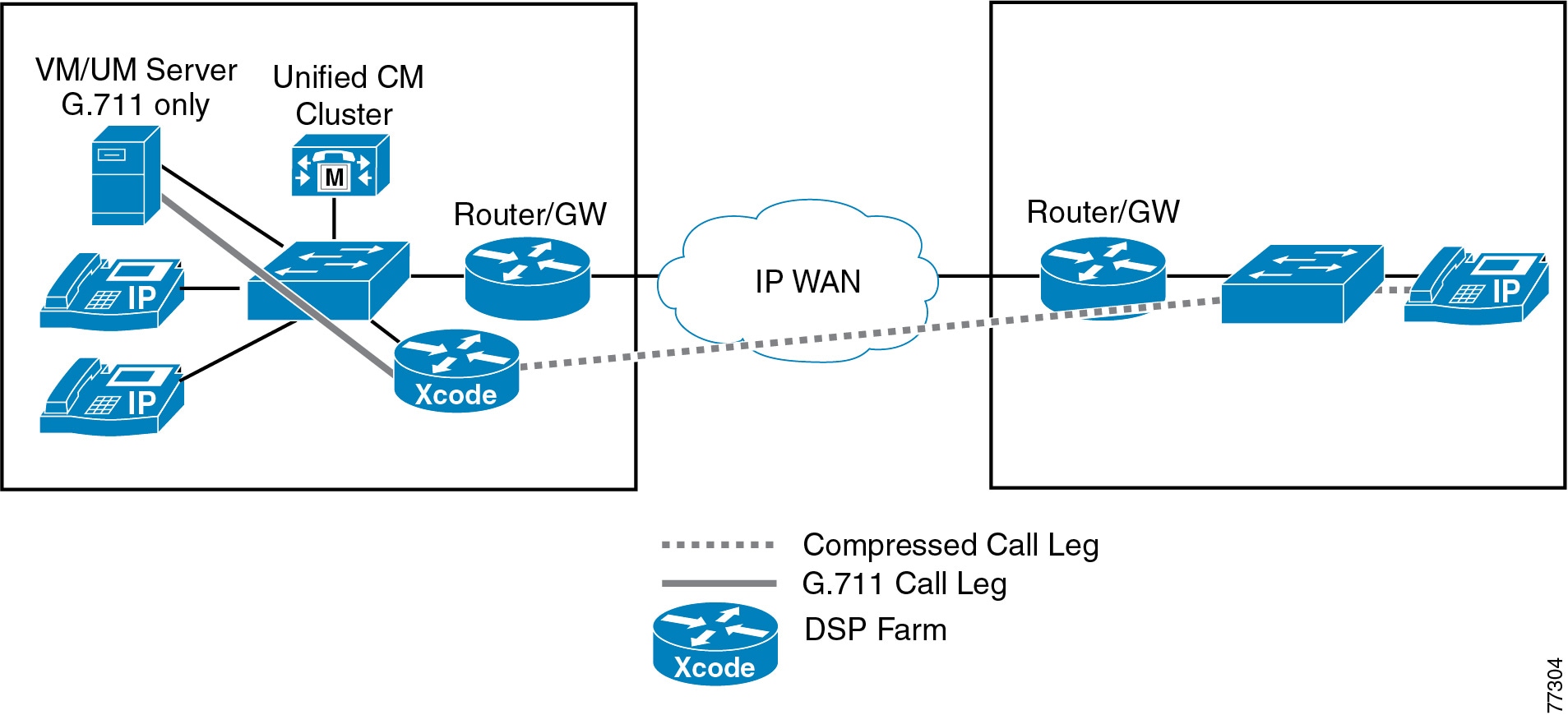
Because WAN bandwidth is typically limited, calls are configured to use a low bit-rate codec such as G.729 when traversing the WAN. (See Figure 6-1.)
Voice compression between IP phones is easily configured through the use of regions and locations in Unified CM. A region defines the type of compression (for example, G.711 or G.729) used by the devices in that region, and a location specifies the total amount of bandwidth available for calls to and from devices at that location.
Figure 6-1 Transcoding for the WAN with Centralized Call Processing
Unified CM uses media resource groups (MRGs) to enable sharing of MTP and transcoding resources among the Unified CM servers within a cluster. In addition, when using an LBR codec (for example, G.729a) for calls that traverse different regions, the transcoding resources are used only if one (or both) of the endpoints is unable to use the LBR codec.
In Figure 6-1, Unified CM knows that a transcoder is required and allocates one based on the MRGL and/or MRG of the device that is using the higher-bandwidth codec. In this case it is the VM/UM server that determines which transcoder device is used. This behavior of Unified CM is based on the assumption that the transcoder resources are actually located close to the higher-bandwidth device. If this system was designed so that the transcoder for the VM/UM server was located at the remote site, then G.711 would be sent across the WAN, which would defeat the intended design. As a result, if there are multiple sites with G.711-only devices, then each of these sites would need transcoder resources when an LBR is run on the WAN.
The placement of other resources is also important. For example, if a conference occurs with three phones at a remote site and the conference resource is located in the central (call processing) site, then three media streams are carried over the WAN. If the conference resource were local, then the calls would not traverse the WAN. It is necessary to consider this factor when designing the bandwidth and call admission control for your WAN.
Multisite WAN Deployments with Distributed Call Processing
In distributed call processing deployments, several sites are connected through an IP WAN. Each site contains a Unified CM cluster that can, in turn, follow the single-site model or the centralized call processing model. A gatekeeper may be used for call admission control between sites.
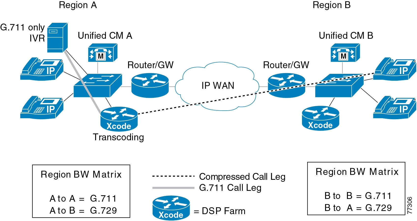
Because WAN bandwidth is typically limited, calls between sites may be configured to use an LBR codec (such as G.729a) when traversing the WAN. H.323v2 intercluster trunks are used to connect Unified CM clusters. Unified CM also supports compressed voice call connections through the MTP service if a hardware MTP is used. (See Figure 6-2.)
A distributed call processing deployment might need transcoding and MTP services in the following situations:
•
•
Figure 6-2 Intercluster Call Flow with Transcoding
Unified CM uses media resource groups (MRGs) to enable sharing of MTP and transcoding resources among the Unified CM servers within a cluster. In addition, for calls across intercluster trunks, MTP and transcoding resources are used only when needed, thus eliminating the need to configure the MTP service for applications that do not support LBR codecs.
The following characteristics apply to distributed call processing deployments:
•
•
IP PSTN Access
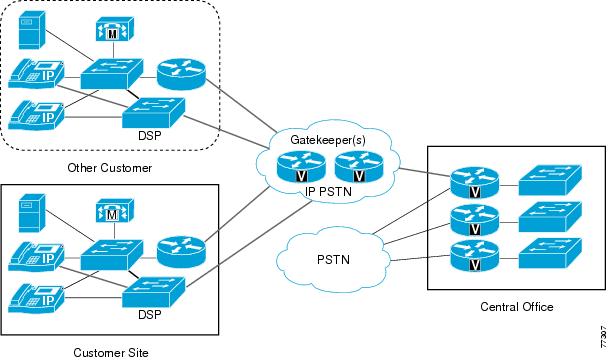
Another application scenario for MTP and transcoding resources involves a service provider that provides its customers with access to an IP PSTN instead of the traditional PSTN. In such a scenario, the gatekeepers reside in the service provider network. In order to simplify the dial plan, each customer is required to use an MTP to anchor its calls, so that the individual IP addresses assigned to the endpoints can be hidden. The service provider's central office can then relay through the traditional PSTN and/or provide IP connectivity to other customers. Figure 6-3 illustrates this deployment model.
Figure 6-3 IP PSTN Access Example
Note that the customer site in Figure 6-3 can use any of the previous three deployment models: single site, multisite WAN with centralized call processing, or multisite WAN with distributed call processing.
The H.323 trunk from the customer site to the IP PSTN must be configured with MTP so that the endpoint IP addresses remain masked. Thus, all external calls use the MTP resources. However, MTP resources can be shared within the Unified CM cluster to achieve more efficient use of the resources. This technique of utilizing MTPs for address hiding may be used for SIP trunks as well.