Feedback
Table Of Contents
Configuring IVR on One Switch Between Two VSANs
Configuring IVR Between Two Switches Using a Transit VSAN
IVR with Brocade and McData Switches Using Interop Mode
Inter-VSAN Routing
Inter-VSAN routing (IVR) facilitates the communication between a target and initiator in different VSANs, using IVR zones and IVR zone sets.
Cross VSAN communication is not permitted by default on a Cisco MDS 9000 switch. If there are two VSANs on a single switch, and one or more of the initiators in one VSAN needs to communicate with one or more of the targets in the other VSAN, IVR enables this communication.
This chapter describes how to configure IVR and includes the following sections:
•
Configuring IVR on One Switch Between Two VSANs
•
•
Configuring IVR on One Switch Between Two VSANs
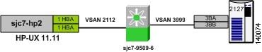
The following recipe provides the steps to configure IVR on a single switch. The example uses both VSANs 2112 and 3999. Before configuring IVR, you need to enable it. (See Figure 6-1.)
Figure 6-1 Single Switch IVR Topology
To configure IVR on one switch between two VSANs, follow these steps:
Step 1
Figure 6-2 Enabling IVR on the Switch
Step 2
Step 3
Figure 6-3 IVR Enable Status on the Switch
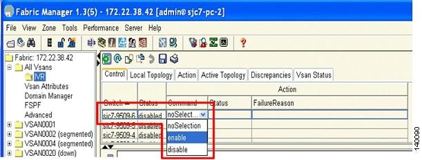
Alternatively, you can enable IVR from the switch by using the enable IVR command.
sjc7-9509-6# conf tEnter configuration commands, one per line. End with CNTL/Z.Sjc7-9509-6(config)# ivr enablesjc7-9509-6(config)#^Zsjc7-9509-6#Step 4
Step 5
Figure 6-4 Inserting IVR Topology
Step 6
Step 7
Step 8
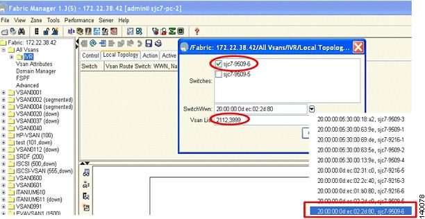
Figure 6-5 shows the switch sjc7-9509-6 selected, its switch WWN, and the VSANs (2112 and 3999) involved in the IVR configuration.
Figure 6-5 Adding Switch WWN and VSANs to Create the IVR Topology
After making these selections, the configuration is updated. You now need to activate the IVR topology.
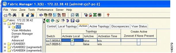
Step 9
Step 10
Figure 6-6 Activating IVR Topology
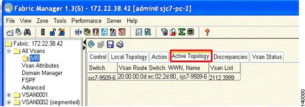
By selecting the Active Topology tab you can see the active topology. The Discrepancies tab shows the discrepancies, if any, that need to be fixed for IVR to function properly. Ideally the discrepancies tab should not have any entries. Figure 6-7 shows the Active Topology tab.
Figure 6-7 Active Topology Tab
The next step is to create an IVR zone set and zones so that the initiator and the target can communicate with each other.
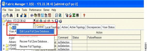
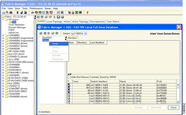
Step 11
Figure 6-8 Edit the IVR Zone on the Switch
Your next step is to create a zone and assign the required members to the zone.
Step 12
Figure 6-9 Insert IVR Zones
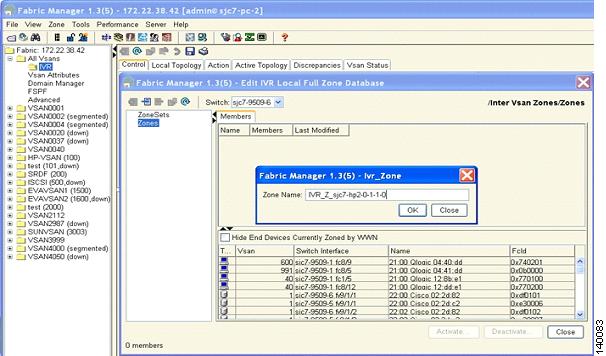
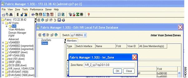
Step 13
Figure 6-10 Naming an IVR Zone
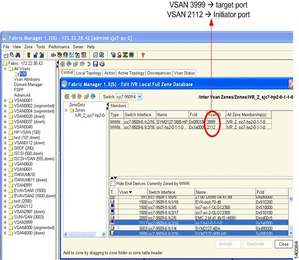
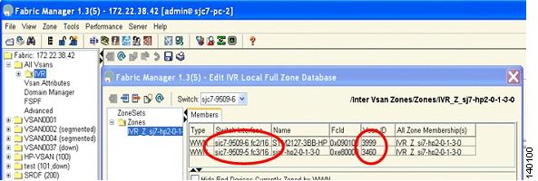
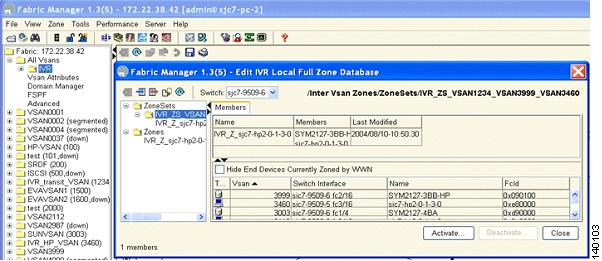
Step 14
Figure 6-11 Members of the IVR Zone
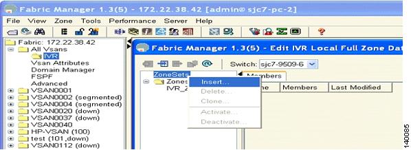
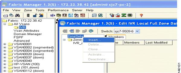
The next step is to create a IVR zone set and add the above zone to the zone set.
Step 15
Figure 6-12 Inserting IVR Zone Sets
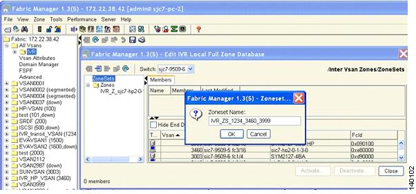
Step 16
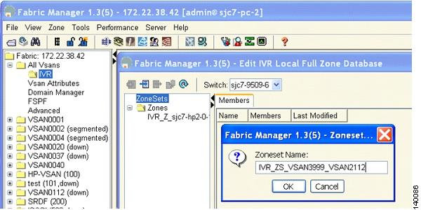
Figure 6-13 Naming an IVR
Step 17
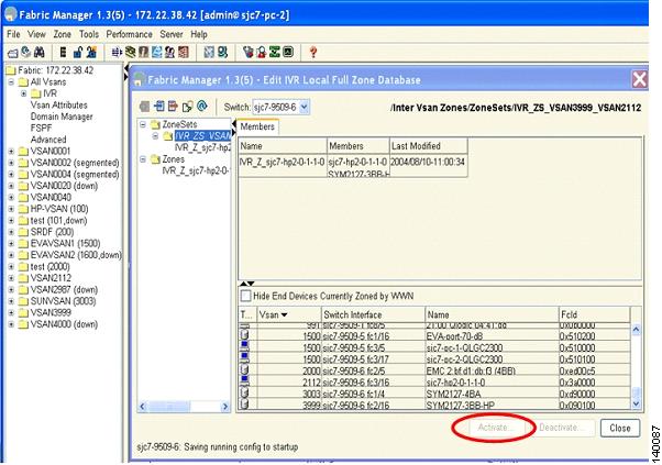
Figure 6-14 Activating an IVR
Step 18
Configuring IVR Between Two Switches Using a Transit VSAN
When two or more switches are involved in an IVR configuration, one or more transit VSANs may be required to support IVR.
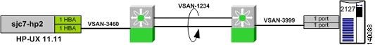
The following recipe uses switches sjc7-9509-6 and sjc7-9509-5. The target (storage) port is on switch sjc7-9509-6 in VSAN 3999 and the initiator is an HP-UX server on switch sjc7-9509-5 in VSAN 3460. VSAN 3999 is only available on switch sjc7-9509-6 and VSAN 3460 is only available on switch sjc7-9509-5. The transit VSAN used is 1234. The topology appears in Figure 6-15.
Figure 6-15 IVR Topology with Two MDS Switches
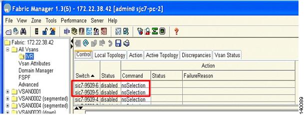
As with any IVR configuration, the switches involved must have IVR enabled on them. In this case, switches sjc7-9509-5 and sjc7-9509-6 need to have IVR enabled. Figure 6-16 shows that IVR is currently disabled on both switches
Figure 6-16 Switches with IVR Disabled
To configure IVR on two switches, follow these steps:
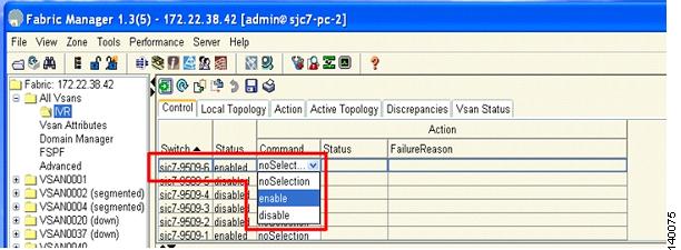
Step 1
Step 2
Figure 6-17 Enabling IVR in sjc7-9509-6
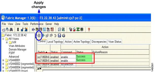
Figure 6-17 shows IVR being enabled for switch sjc7-9509-6. Follow the same procedure to enable IVR for switch sjc7-9509-5.
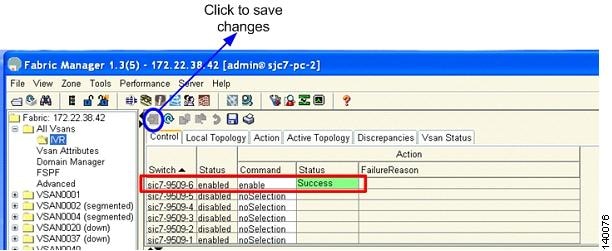
Step 3
Figure 6-18 Saving IVR Changes
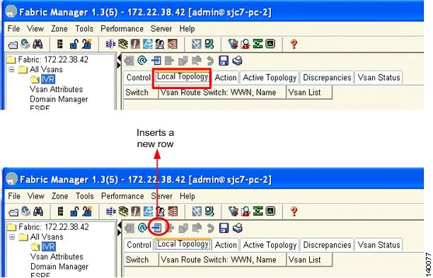
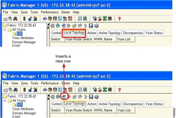
The next step is to create the IVR topology.
Step 4
Step 5
Figure 6-19 Create IVR Topology
Step 6
Step 7
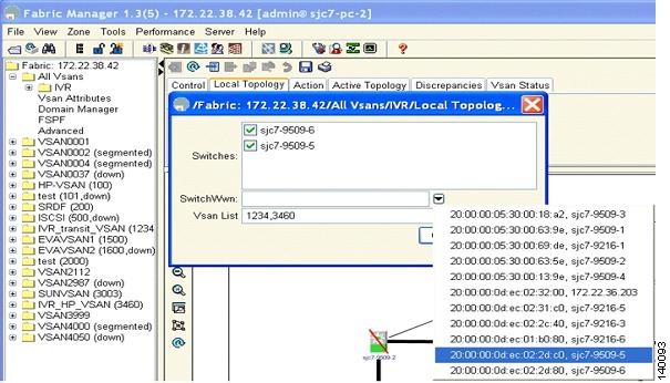
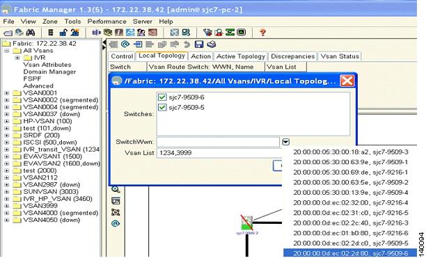
Figure 6-20 shows that the switches sjc7-9509-5 and sjc7-9509-6 are both selected in the Switches dialog box. In the Switch WWN dialog box, the WWN of switch sjc7-9509-5 is selected. In the VSAN list, the VSANs that need to be added to complete the IVR topology are shown. In this case it is VSAN 1234 (transit VSAN) and 3460 (host VSAN). This will create the first half of the topology required to make IVR work.
Figure 6-20 Phase One of the IVR Topology Configuration
Step 8
Figure 6-21 Phase Two of the IVR Topology Configuration
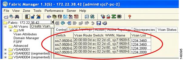
After the configuration, the local topology is shown in Figure 6-22. As can be seen, both switches have knowledge of all the VSANs involved in the IVR configuration.
Figure 6-22 Configured IVR Local Topology
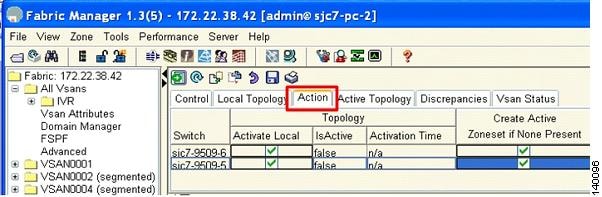
The next step is to activate the configured IVR topology.
Step 9
Step 10
Figure 6-23 Activating IVR Topology
Tip
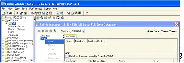
The next step is to create a IVR zone set and zones so that the initiator and the target can communicate with each other.
Step 11
Figure 6-24 Edit IVR Zone Set on the Switch
Step 12
Figure 6-25 Insert IVR Zones
The next step is to give the zone a name.
Step 13
Figure 6-26 Naming an IVR Zone
Step 14
Figure 6-27 Members of the IVR Zone
The next step is to create the IVR zone set and activate the zone set to complete the IVR configuration.
Step 15
Figure 6-28 Inserting IVR Zone Sets
Step 16
Figure 6-29 IVR Zone Set
Step 17
Figure 6-30 Adding an IVR Zone to an IVR Zone Set
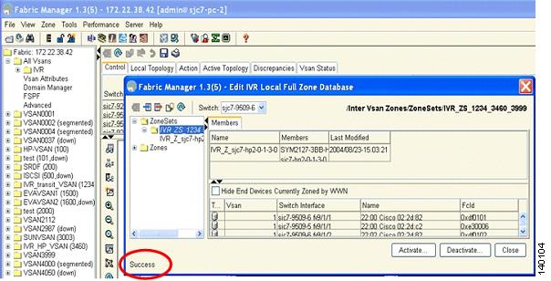
Step 18
Figure 6-31 Activating an IVR Zone Set
Step 19
The two-switch IVR configuration is now complete.
IVR with Brocade and McData Switches Using Interop Mode
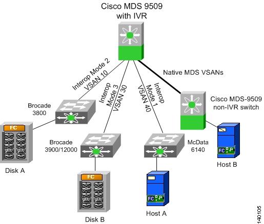
The procedure to configure IVR in interop mode with third-party switches is the same as described in the preceding recipes. You can use IVR in conjunction with Brocade and McData switches. When a third- party switch is present in the topology, they can be located either in the transit VSAN or as an edge switch connecting to an MDS 9000 switch enabled for IVR. Third-party switches cannot be used as IVR gateways. Figure 6-32 shows topologies such as these.
Figure 6-32 Sample IVR Topology with Interop Modes
For the third-party switches to function properly in an IVR configuration, they must be configured in a VSAN interop mode. IVR works with all three interop modes (1, 2, and 3). For more details on interoperability, refer to the MDS Switch to Switch Interoperability Configuration Guide located on http://www.cisco.com/en/US/partner/products/hw/ps4159/ps4358/products_mds_integration_list.html.
When a McData switch is present, the domain ID of the destination switch needs to be in the interop range. That is, the domain ID of the switch in a VSAN has to be between 97 and 127 for IVR to function properly. This means that a device on a McData switch cannot send a frame to a device in another VSAN, regardless of the interop mode, that is outside of the 97 to127 domain ID range.