Feedback
Table Of Contents
Before You Begin the Installation
Downloading a PIX 515 Image over TFTP
Upgrading the PIX 515 Activation Key
Installing a PIX 520 or Earlier Model
PIX Firewall with a Four-Port Interface Card
Installing for the First Time or Installing an Activation Key
Installing a PIX Firewall
This chapter includes the following sections, which describe how to install a PIX 515, PIX 520, and earlier models:
•
Before You Begin the Installation
•
Installation Overview
Follow these steps to install a PIX Firewall.
Note
Step 1
Step 2
Step 3
Step 4
If you are installing a PIX 520 or upgrading an earlier model, refer to "Installing a PIX 520 or Earlier Model"; otherwise, for the PIX 515, continue "Installing a PIX 515."
Before You Begin the Installation
Note
Before you begin the installation, gather the following information about each network interface that will be connected to the PIX Firewall:
outside
inside
0
100
To prepare to configure the PIX Firewall, locate the following information:
•
•
•
•
•
•
In addition, you should determine the following:
1
2
Installing a PIX 515
This section describes how to install a PIX 515 and also the following topics:
•
•
To install a PIX 515:
Step 1
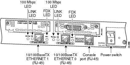
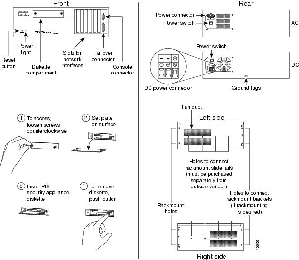
Figure 2-1 PIX 515 Features
This graphic shows the Ethernet connectors where you connect your inside and outside network cables, the Console port used to connect a computer to the PIX 515, the optional failover connector (requires a PIX-515-UR license to use), and LEDs for the various transmission states:
•
•
•
The USB port to the left of the Console port is not used. The detachable plate above the ETHERNET 1 connector is also not used.
lists the PIX 515 front panel's LEDs.
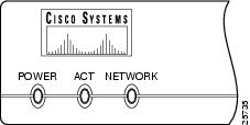
Figure 2-2 PIX 515 Front Panel LEDs
The LEDs are:
•
•
•
Step 2
Step 3
Step 4
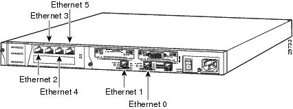
Figure 2-3 Four-Port Ethernet Connectors in a PIX 515
Connect the perimeter network cables to the card starting with the left connector and moving to the right. (The four-port interface card requires the PIX-515-UR license to be accessed.) Starting from the left the connectors are Ethernet 2, Ethernet 3, Ethernet 4, and Ethernet 5. The maximum number of allowed interfaces is 6; do not add a single-port card in the extra slot below the four-port card.
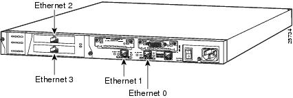
Figure 2-4 Two Single-Port Ethernet Connectors in a PIX 515
As shown in , if your unit has one or two single-port Ethernet cards installed in the auxiliary assembly on the left of the unit at the rear, the cards are numbered top to bottom so that the top card is Ethernet 2 and the bottom card is Ethernet 3. (Additional interface cards require the PIX-515-UR license to be accessed.)
Step 5
Step 6
Step 7
Step 8
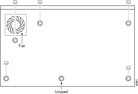
Figure 2-5 Attaching the Rubber Feet
to the PIX 515
If you want to install the PIX 515 in an equipment rack, two sets of brackets are provided in your accessory kit:
–
–
Note
To install the unit horizontally in an equipment rack:
(a)
(b)
(c)
To install the unit vertically in an equipment rack:
(a)
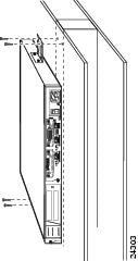
Figure 2-6 Attaching a Bracket for Vertical Mounting
(b)
Figure 2-7 Installing the PIX 515 Vertically
Step 9
Step 10
What to Do Next
If you are installing a PIX 515 with the PIX-515-R restricted feature license, you can optionally install the PIX Firewall Syslog Server as described in "." All other chapters in this guide do not apply to the PIX 515 with a restricted license.
If you have a PIX-515-UR unrestricted feature license, the following options are available:
•
•
•
•
Note
When you are done, refer to the configuration guide for your respective software version listed in the section, "Related Documentation" in "About This Manual."
Downloading a PIX 515 Image over TFTP
The PIX 515 receives its boot image from either Flash memory or by downloading the image from a TFTP server. (You can obtain a TFTP server as an option from Cisco, you can use the TFTP server provided with UNIX, or you can use a TFTP server available for your computer.)
Because the PIX 515 does not have a diskette drive, you need to send a binary image to the PIX 515 using Trivial File Transfer Protocol (TFTP). The PIX 515 has a special mode called ROM monitor mode that lets you retrieve the binary image over the network.
Note
Note
Note
Note
TFTP Overview
After the PIX 515 restarts, it pauses 10 seconds. To start the ROM monitor, press the Escape key or send a BREAK character. If you are using Windows HyperTerminal, you can press the Esc (Escape) key or send a BREAK character by pressing the ctrl and break keys. From a Telnet session to a terminal server that has serial access to the PIX 515, use ctrl ] to get the Telnet command prompt, and then enter the send break command. If you do not want to enter boot mode when the PIX 515 restarts, press the space bar to start the normal boot immediately, or wait until the 10 seconds passes and the PIX 515 will boot normally from Flash memory.
From ROM monitor, you can enter a number of commands that let you specify the file and location of the configuration image, and then download it to the PIX 515. The ROM monitor also lets you ping the TFTP server to see if it is online and to specify the IP address of the nearest router if the image is not on a subnet shared with a PIX 515 interface.
Note
The TFTP server should be installed, but is not required to be, on the most secure part of the network, preferably on the inside interface.
After you download an image, use the write memory command to store the image in Flash memory.
The monitor feature only works on the PIX 515 and not with earlier models of the PIX Firewall.
The maximum length of a filename is 122 characters.
If the TFTP service stops receiving data requests during a file transfer, it waits four seconds and then closes the connection.
Downloading an Image
To download an image over TFTP:
Step 1
Note
The monitor> prompt appears.
Step 2
Step 3
Step 4
Step 5
Step 6
Step 7
Step 8
Step 9
An example follows:
Rebooting....PIX BIOS (4.0) #47: Sat May 8 10:09:47 PDT 1999Platform PIX-520Flash=AT29C040A @ 0x300Use BREAK or ESC to interrupt flash boot.Use SPACE to begin flash boot immediately.Flash boot interrupted.0: i8255X @ PCI(bus:0 dev:13 irq:11)1: i8255X @ PCI(bus:0 dev:14 irq:10)Using 1: i82558 @ PCI(bus:0 dev:14 irq:10), MAC: 0090.2722.f0b1Use ? for help.The example continues:
monitor> ?? this help messageaddress [addr] set IP addressfile [name] set boot file namegateway [addr] set IP gatewayhelp this help messageinterface [num] select TFTP interfaceping <addr> send ICMP echoreload halt and reload systemserver [addr] set server IP addresstftp TFTP downloadtimeout TFTP timeouttrace toggle packet tracingmonitor> addr 192.168.1.1address 192.168.1.1monitor> serv 192.168.1.2server 192.168.1.2monitor> file cdiskfile cdiskmonitor> ping 192.168.1.2Sending 5, 100-byte 0x5b8d ICMP Echoes to 192.168.1.2, timeout is 4 seconds:!!!!!Success rate is 100 percent (5/5)monitor> tftptftp cdisk@192.168.1.2................................Received 626688 bytesPIX admin loader (3.0) #0: Tue May 11 10:43:02 PDT 1999Flash=AT29C040A @ 0x300Flash version 4.9.9.1, Install version 4.4.1Installing to flash...Upgrading the PIX 515 Activation Key
Note
To upgrade an activation key on the PIX 515:
Step 1
Step 2
Step 3
Step 4
Step 5
Step 6
Step 7
Step 8
When done, refer to "After the Prompts" for additional prompts information that displays when a PIX Firewall starts up.
Installing a PIX 520 or Earlier Model
To install a PIX 520 or earlier model:
Step 1
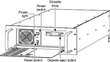
Figure 2-8 PIX 520 Front, Rear, and Side Panels.
lists the controls on earlier PIX Firewall models.
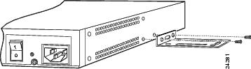
Figure 2-9 Earlier PIX Firewall Access
Step 2
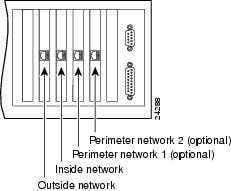
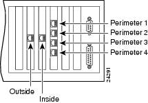
If you are not installing a four-port Ethernet card, which is supported only with version 4.4(1) and later, add the cables as shown in . The outside interface card must be in slot 0 (zero), which is the leftmost slot in the unit. The inside interface card can be in slot 1 or you can skip a slot. The PIX Firewall assumes that the next card it finds will be the inside interface even if an empty slot is left between the outside and inside interfaces.
Figure 2-10 Up to Four Single-Port Interfaces in a PIX Firewall
PIX Firewall version 2 supports two interfaces, version 3 supports three interfaces, versions 4.0 and 4.1 support three interfaces, version 4.2 supports four interfaces, version 4.3 supports four interfaces, and version 4.4 supports six interfaces.
PIX Firewall with a Four-Port Interface Card
As of PIX Firewall version 4.4(1) and later, you can install one optional four-port Ethernet interface card in the PIX 520 and earlier hardware models.
Note
The Cisco four-port Ethernet interface card provides four 10/100 Ethernet connections and has autosense capability. Connectors on the four-port card are numbered top to bottom sequentially; however, the actual device number depends on the slot in which the four-port card is installed. shows how the top connector is numbered
.
With the four-port card, having a card in slot 3 makes the number of interfaces greater than six; while the card in slot 3 cannot be accessed, its presence does not cause problems with the PIX Firewall.
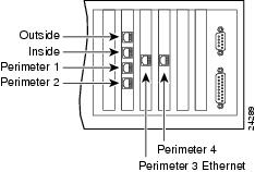
shows the location of the interfaces if you install a four-port card in slot 0.
Figure 2-11 Four-Port Ethernet Interface Installed in Slot 0
From this figure you can see that because the four-port card is numbered from the top down, the outside interface, which must be the first interface, is associated with the topmost connector.
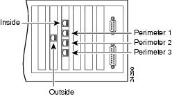
shows how the slots are numbered if a single-port interface card is inserted in slot 0.
Figure 2-12 Four-Port Ethernet Interface Installed in Slot 1
shows how the slots are numbered if single-port interface cards are installed in slot 0 and in slot 1.
Figure 2-13 Four-Port Ethernet Interface Installed in Slot 2
Step 3
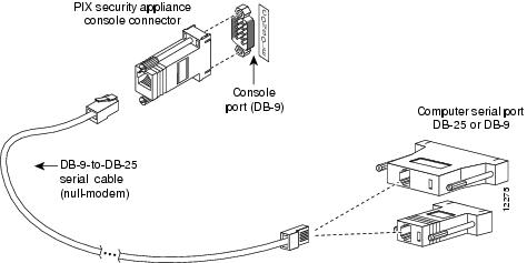
Figure 2-14 PIX Firewall Serial Cable Assembly
Step 4
Step 5
Step 6
If you are installing a DC voltage PIX Firewall, refer to ""."
Step 7
(a)
(b)
(c)
(d)
(e)
Startup Messages
When you reboot or power-on the PIX Firewall, messages appear similar to the following. The first messages to display are:
PIX Bios V2.7Booting Floppy...................................Execing flopPIX Floppy loader (V2.0)Reading second stage loader.....Starting second stage loader.PIX flash loader (V2.0)Flash=AT29C040AReading floppy image..................................Flash version 4.4, Floppy version 4.4The Flash statement indicates the type of Flash memory. Version 4.3 and 4.4 require that the Flash be 2 MB, which has the "AT29C040A" code. If you had the previous version, the 512 KB, PIX Firewall would have displayed an error message and stopped the installation.
The last line in this example lists the software versions in Flash memory and what you are installing on diskette.
When a Diskette is Inserted
When a diskette is inserted in the PIX Firewall unit's drive, you are prompted with the following prompt:
Do you want me to install floppy version onto flash? [n]If you have an existing configuration, enter n for no. Alternatively, you can ignore the prompt by waiting approximately 45 seconds and PIX Firewall will insert No for you.
The listing continues as follows:
Installing to flashIf you did not install the diskette version into Flash memory, proceed to "After the Prompts."
Installing for the First Time or Installing an Activation Key
If you are installing for the first time or you want to enter a new activation key, enter y for yes. PIX Firewall then displays:
Activation Key: aaaabbbb ccccddd eeeeffff 11112222Do you want to enter a new activation key? [n]If you do not wish to enter an activation key, enter n for no, or wait approximately 45 seconds and PIX Firewall will enter No for you. If you enter y to enter an activation key, you are prompted to enter each part of the activation key:
Enter Activation KeyPart 1 of 4:Enter the first part of your new activation key. (In the previous example for the activation key listing, the first part is aaaabbbb.)
PIX Firewall then prompts you for the other 3 parts of the activation key. Enter each part.
Part 2 of 4:Part 3 of 4:Part 4 of 4:After the Prompts
PIX Firewall then continues the startup messages as follows:
Using flash configErasing flash...Writing image into flash...Saving config...16MB RAMFlash=AT29C040A @ 0x300To install version 4.4, you need to see at least 16 MB of RAM. If you had too little memory, a message would display indicating "insufficient memory."
PIX Firewall then lists each interface. Because PIX Firewall interface cards are polled instead of using interrupts, the IRQ (interrupt request lines) can have duplicate numbers:
mcwa i82557 Ethernet at irq 10 MAC: 00a0.c90a.eb4dmcwa i82557 Ethernet at irq 9 MAC: 00a0.c986.8eeamcwa i82557 Ethernet at irq 10 MAC: 00a0.c9e8.8cafmcwa i82557 Ethernet at irq 11 MAC: 0090.2710.4aa4In this example, the PIX Firewall has four Ethernet interfaces. The MAC address is a unique hardware identifier for each interface.
If a Private Link card is present, the following message appears:
CA9568 Encryption @ 0x3a0The PIX Firewall symbol then displays followed by the version number and the number of connections.
-----------------------------------------------------------------------|| |||| |||||| ||||..:||||||:..:||||||:..c i s c o S y s t e m sPrivate Internet eXchange-----------------------------------------------------------------------PIX FirewallPIX Version 4.4(x)
Note
If a Private Link card is present, the following export statement appears:
****************************** Warning *******************************An encryption device has been discovered.This product is not authorized for use by persons located outside theUnited States and Canada that do not have export license authorityfrom Cisco Systems, Inc. and/or the U.S. Government.This product may not be exported outside the U.S. and Canada either byphysical or electronic means without the prior written approval ofCisco Systems, Inc. and/or the U.S. Government.Persons outside the U.S. and Canada may not reexport, resell, ortransfer this product by either physical or electronic means withoutprior written approval of Cisco Systems, Inc. and/or U.S. Government.******************************* Warning *******************************PIX Firewall then displays the following messages:
Copyright (c) 1996-1999 by Cisco Systems, Inc.Restricted Rights LegendUse, duplication, or disclosure by the Government issubject to restrictions as set forth in subparagraph(c) of the Commercial Computer Software - RestrictedRights clause at FAR sec. 52.227-19 and subparagraph(c) (1) (ii) of the Rights in Technical Data and ComputerSoftware clause at DFARS sec. 252.227-7013.Cisco Systems, Inc.170 West Tasman DriveSan Jose, California 95134-1706Type help or '?' for a list of available commands.pixfirewall> enableEnter the enable command to start unprivileged mode. You are then prompted for the enable password as follows:
Password:Unless you have assigned a value to the enable password, which you can do with the enable password command, press the Enter key to signify the default of no password. You are now in unprivileged mode.
Start configuration mode by entering the configure terminal command:
pixfirewall# configure terminalpixfirewall(config)#You are now ready to start configuring your PIX Firewall, which is described in the configuration guide for your version of the PIX Firewall. Refer to the section, "Related Documentation" in "About This Manual."