Feedback
Table Of Contents
Frequently Asked Failover Questions
Installing Failover
This chapter includes the following sections:
•
Installing the Failover Cable
•
Installing the Failover Cable
Follow these steps to install a failover Standby unit.
Step 1
Step 2
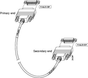
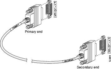
Install the cable for the PIX 515 as shown in or as shown in for the PIX 520 and earlier models.
Figure 3-1 PIX 515 Failover Cable Connection
Figure 3-2 PIX 520 and Earlier Model Failover Cable Connection
Step 3
Step 4
Step 5
Step 6
Within a few seconds, the Active unit automatically downloads its configuration to the Standby unit. The two units are now operating in failover mode. The first PIX Firewall (the one you configured) is the primary unit, and is active by default. The second PIX Firewall is the secondary unit, acting as failover Standby.
If the primary unit fails, the secondary unit automatically becomes active.
All further PIX Firewall configuration for this failover pair must be done on the Active unit, whichever unit that might be at the time you perform the configuration. The Active unit automatically updates the configuration on the Standby unit. If the Standby unit has failed, updating takes place as soon as the Standby unit is brought back into operation.
Refer to Chapter 3, "Advanced Configurations" in the configuration guide for your respective software version listed in the section, "Related Documentation" in "About This Manual."
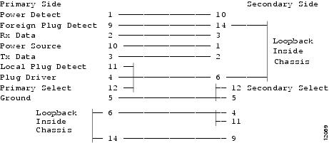
Failover Cable Pinouts
Should you need to test the cable you received, the pinouts are shown in .
Figure 3-3 Failover Cable Pinouts
Frequently Asked Failover Questions
This section contains some frequently asked questions about the failover feature.
•
No, failover will not work without the cable. If you run without the failover cable you are essentially running two separate PIX Firewall units. This will result in a bridge loop and flood the network. The failover cable is an essential part of failover.
•
No, the cable cannot be extended using modems or other RS-232 line extenders. Part of what the failover cable does is indicate the presence and power status of the other unit. When you place line extenders in this path you are relaying the status of the line extender rather than of the other PIX Firewall unit.
•
When the Active PIX Firewall experiences a power failure, the Standby PIX Firewall comes up in active mode. If the Primary unit is powered on again it will become the Standby unit.
•
When the active PIX Firewall fails by disconnecting the interface (cable pull), the Standby PIX Firewall becomes the Active unit. When the interface is plugged back in, the unit automatically recovers, and its status is changed from failed to Standby.
•
Yes, if you are running PIX Firewall version 4.2.x or later on both units.
•
Fault detection is based on the following:
•
•
•
Refer to the "Failover" section in Chapter 3, "Advanced Configurations" in the configuration guide for your respective software version listed in the section, "Related Documentation" in 'About This Manual.'