Feedback
Table Of Contents
Installing a DC Voltage PIX Firewall
Installing a DC Voltage PIX Firewall
Note
Only a DC power source that complies with the safety extra low voltage (SELV) requirements in UL 1950, CSA 22.2-950, EN60950, and EN41003 can be connected to a PIX Firewall DC-input power supply.
Note
Note
Before performing any of the following procedures, ensure that power is removed from the DC circuit. To ensure that all power is OFF, locate the circuit breaker on the panel board that services the DC circuit, switch the circuit breaker to the OFF position, and tape the switch handle of the circuit breaker in the OFF position.
To install the PIX Firewall DC power model:
Step 1
Step 2
Step 3
Step 4
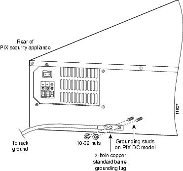
Figure 8-1
Attaching a Grounding Lug to the PIX Firewall
Step 5
Step 6
Step 7
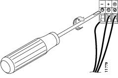
Figure 8-2 Attaching DC power cables
Step 8
Step 9
Step 10
Note
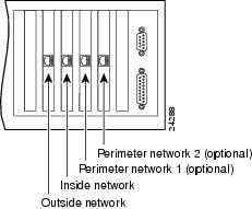
Figure 8-3 PIX Firewall Network Interfaces
Step 11
Note
Your unit is now ready to configure. Refer to configuration guide for your PIX Firewall version described in the section, "Related Documentation" in "About This Manual."