Cisco AS5850 Universal Gateway Card Guide
Replacing or Installing Server Cards

Table Of Contents

Replacing or Installing Server Cards

Online Insertion and Removal

Busyout Command

Required Materials

Removing a Server Card

Installing a Card


Replacing or Installing Server Cards


This chapter describes the procedures for replacing or installing server cards in the Cisco AS5850 chassis.

Online Insertion and Removal

The Cisco AS5850 universal gateway supports online insertion and removal (OIR). This feature allows you to remove and replace a route switch controller card or server card while the system is operating, without affecting system operation.

Each route switch controller card and server card contains a female connector that connects to a male connector on the system backplane. Each male backplane connector comprises a set of tiered pins in two lengths.

Each route switch controller card and server card is designed with two ejector levers to be used when you install or remove a card. The function of the ejector levers is to align and securely seat the card connectors in the backplane. The backplane connector for the route switch controller cards works only in slots 6 and 7. The server card backplane connectors work only in slots 0 through 5 and 8 through 13.


Caution Do not force the route switch controller cards or server cards into a slot, because this can damage the backplane connector pins if they are not aligned properly with the card connectors.


Note There is a separate procedure for OIR of an RSC card. Refer to the maintenance chapter in the Cisco AS5850 Operations, Administration, Maintenance, and Provisioning Guide, available online at: http://www.cisco.com/univercd/cc/td/doc/product/access/acs_serv/as5850/sw_conf/5850oamp/ index.htm.


Busyout Command

To remove a server card without dropping calls or connections, you must first take the card out of service by using the busyout command to remove DS-0s and modem resources from the available pool as calls are completed. The busyout command is executed on a per-card (slot) basis for line connections, and port connections can be busied out at the slot, SPE or individual port level.

The busyout command has the format busyout slot-number, where slot-number is 0 through 5 or 8 through 13. The following example shows how to busyout the card in slot 0:

Router# busyout 0
Router#

If you are replacing a failed card, we recommend that you proceed as follows:

1. Use the busyout command to take the card out of service.

2. Remove the existing card.

3. Install the new card in the same slot.

If you are replacing a server card with a new server card of the same type in the same slot, the system software recognizes the new server card interfaces and brings them up automatically. No additional configuration is needed. A server card installed in a different slot may need additional configuration.


Note The system brings online only the interfaces that match the current configuration and that were previously configured as up; all other interfaces require that you configure them with the configure command. For information on the configure command, refer to the Cisco AS5850 Universal Gateway Commissioning Guidelines that shipped with your system.


Required Materials

You need the following supplies to install a server card. Contact a service representative for ordering information if you need additional materials.

Server card

Interface cables and cable ties

No. 2 Phillips screwdriver

Your own ESD-prevention equipment or the disposable grounding wrist strap included with all upgrade kits, field-replaceable units (FRUs), and spares

Antistatic mat or foam pad, and an antistatic bag (if replacing an installed and configured card with a new card)

Cisco AS5850 Operations, Administration, Maintenance, and Provisioning Guide, available online at http://www.cisco.com/univercd/cc/td/doc/product/access/acs_serv/as5850/sw_conf/5850oamp/ index.htm

Cisco AS5850 Universal Gateway Card Guide (this guide)

Cisco AS5850 Universal Gateway Regulatory Compliance and Safety Information

Removing a Server Card

To remove a server card from the Cisco AS5850, complete the following steps:


Warning Before opening the chassis, disconnect the telephone-network cables to avoid contact with telephone network voltages. To see translations of the warnings that appear in this publication, refer to the Regulatory Compliance and Safety Information document that accompanied this device.


Caution Trunk cards weigh 8 lb (3.6 kg) each. Use two hands when removing or replacing a trunk card.


Caution To avoid erroneous failure messages, remove or insert only one server card at a time. Also, after inserting or removing a server card, allow at least 15 seconds before removing or inserting another server card so that the system can reinitialize and note the current configuration of all interfaces.


Step 1 Note the slot in which the card is installed. If you are replacing a server card with a new server card of the same type in the same slot, the system software recognizes the new server card interfaces and brings them up automatically. No additional configuration is needed.

Step 2 Initialize the software busyout procedure by entering the following console command in privileged EXEC mode:

busyout slot-number

Step 3 Verify that the yellow maintenance LED on the card comes on, which indicates that the card is offline and is ready to be removed.

Step 4 Attach an ESD-preventive wrist strap between you and an unpainted chassis surface.


Caution To prevent ESD damage, handle cards by ejector levers and carrier edges only, and use an ESD-preventive wrist strap or other grounding device.

Step 5 Disconnect all cables and secure them out of the way, using cable ties, if necessary.

Step 6 Using a No. 2 Phillips screwdriver, loosen the panel fasteners at the top and bottom of the card front panel. (See Figure 1-1.)

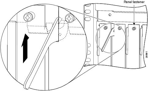
Figure 1-1 Using the Ejector Lever

Step 7 Pull either the top or bottom ejector lever away from the card's front panel to disengage the card from the backplane connector. (See Figure 1-1.)


Caution Always use the ejector levers to disengage or seat server cards in the backplane. Failure to do so can cause erroneous system error messages indicating a card failure. However, do not use the ejector levers to lift or support the weight of the cards.

Step 8 Grasp the ejector levers and pull the card partially out of the server slot until you can grasp the card front panel with one hand. Place your other hand under the card to balance the weight of the card as you pull it out of the slot. (See Figure 1-2.)


Warning High-performance devices on this card can get hot during operation. To remove the card, hold it by the faceplate and bottom edge. Allow the card to cool before touching any other part of it or placing it in an antistatic bag. To see translations of the warnings that appear in this publication, refer to the Regulatory Compliance and Safety Information document that accompanied this device.


Figure 1-2 Removing or Replacing a Server Card

Step 9 Pull the card straight out of the slot. Avoid touching the circuitry or any connector pins.

Step 10 Place the removed card on an antistatic mat or foam pad until you are ready to reinstall it in the chassis. If you plan to return the card to the factory, place it in an antistatic bag.

This completes the server card removal procedure. To install a server card, proceed to the following section, "Installing a Card."


Installing a Card

To install a new server card in the Cisco AS5850, follow these steps:


Caution Trunk cards weigh 8 lb (3.6 kg) each. Use both hands when removing or replacing a card.


Caution To avoid erroneous failure messages, remove or insert only one server card at a time. Also, after inserting or removing a server card, allow at least 15 seconds before removing or inserting another server card so that the system can reinitialize and note the current configuration of all interfaces.


Step 1 Attach an ESD-preventive wrist strap between you and an unpainted chassis surface.


Caution To prevent ESD damage, handle cards by ejector levers and carrier edges only, and use an ESD-preventive wrist strap or other grounding device.

Step 2 Carefully align the card carrier guides with the top and bottom grooves in the server slot. Avoid touching the circuitry or any connector pins.

Step 3 Slide the card into the slot until the ejector levers make contact with the chassis frame. (See Figure 1-2.)

Step 4 Seat the card in the backplane by pushing the card firmly until the ejector levers fold in toward the card's front panel and the front panel is flush with the chassis frame.


Caution Always use the ejector levers to disengage or seat trunk cards, port cards, or route switch controller cards in the backplane. Failure to do so can cause erroneous system error messages indicating a card failure. However, do not use the ejector levers to lift or support the weight of the cards.

Step 5 Tighten the panel fasteners using a No. 2 Phillips screwdriver. This secures the backplane connection and ensures proper EMI shielding.


Caution Always tighten the panel fasteners. These fasteners prevent accidental removal and provide proper grounding for the system.

Step 6 Repeat Step 2 through Step 5 for any other server cards you want to install.

Step 7 Install a blank filler card (DS58-BLANK=) in all empty card slots to keep the chassis dust-free and maintain proper airflow.


Caution To prevent the overheating of internal components, always install blank filler cards in empty slots to maintain the proper flow of cooling air across the cards.

This completes the server card replacement procedure.