Feedback
Table Of Contents
T1 and E1 Cable and Port Pinouts
Attaching the 8-Port Interface Cable to a Bracket (Optional)
SDH/STM-1 Trunk Card Optical Cables
SDH/STM-1 Test Port Adapter Cable
Cabling Specifications
This appendix provides cabling and pinout information for the trunk cards for the Cisco AS5850 universal gateway:
•
T1 and E1 Cable and Port Pinouts
•
•
•
Note
T1 and E1 Cable and Port Pinouts
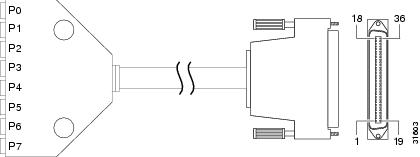
Figure A-1 shows a diagram of the 8-port T1/E1 interface cable.
Figure A-1 8-Port T1/E1 Interface Cable
Table A-1 lists the port pinouts for the 8-port serial port.
Table A-1 8 PRI T1/E1 Interface Cable
SHELL
GROUND
SHELL/BRAID
GROUND
SHELL
J1-11
J1-2
RX_TIP
RX_RING
Twisted pair #1
Port 7
<------
<------
RX_TIP
RX_RING
J9-11
J9-2
J1-3
J1-4
RX_TIP
RX_RING
Twisted pair #1
Port 6
<------
<------
RX_TIP
RX_RING
J8-1
J8-2
J1-5
J1-6
RX_TIP
RX_RING
Twisted pair #1
Port 5
<------
<------
RX_TIP
RX_RING
J7-1
J7-2
J1-7
J1-8
RX_TIP
RX_RING
Twisted pair #1
Port 4
<------
<------
RX_TIP
RX_RING
J6-1
J6-2
J1-9
J1-10
No Connect
No Connect
—
—
No Connect
No Connect
—
J1-11
J1-12
RX_TIP
RX_RING
Twisted pair #1
Port 3
<------
<------
RX_TIP
RX_RING
J5-1
J5-2
J1-13
J1-14
RX_TIP
RX_RING
Twisted pair #1
Port 2
<------
<------
RX_TIP
RX_RING
J4-1
J4-2
J1-15
J1-16
RX_TIP
RX_RING
Twisted pair #1
Port 1
<------
<------
RX_TIP
RX_RING
J3-1
J3-2
J1-17
J1-18
RX_TIP
RX_RING
Twisted pair #1
Port 0
<------
<------
RX_TIP
RX_RING
J2-1
J2-2
J1-19
J1-20
TX_TIP
TX_RING
Twisted pair #2
Port 7
------>
------>
TX_TIP
TX_RING
J9-4
J9-5
J1-21
J1-22
TX_TIP
TX_RING
Twisted pair #2
Port 6
------>
------>
TX_TIP
TX_RING
J8-4
J8-5
J1-23
J1-24
TX_TIP
TX_RING
Twisted pair #2
Port 5
------>
------>
TX_TIP
TX_RING
J7-4
J7-5
J1-25
J1-26
TX_TIP
TX_RING
Twisted pair #2
Port 4
------>
------>
TX_TIP
TX_RING
J6-4
J6-5
J1-27
J1-28
No connect
No connect
—
—
No Connect
No Connect
—
J1-29
J1-30
TX_TIP
TX_RING
Twisted pair #2
Port 3
------>
------>
TX_TIP
TX_RING
J5-4
J5-5
J1-31
J1-32
TX_TIP
TX_RING
Twisted pair #2
Port 2
------>
------>
TX_TIP
TX_RING
J4-4
J4-5
J1-33
J1-34
TX_TIP
TX_RING
Twisted pair #2
Port 1
------>
------>
TX_TIP
TX_RING
J3-4
J3-5
J1-35
J1-36
TX_TIP
TX_RING
Twisted pair #2
Port 0
------>
------>
TX_TIP
TX_RING
J2-4
J2-5
1 J1 connector is male 36 position plug. J2-29 connectors are female RJ-45 receptacles.
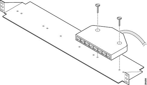
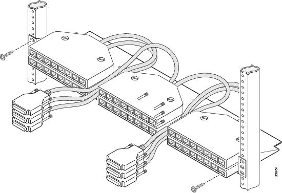
Attaching the 8-Port Interface Cable to a Bracket (Optional)
To attach the 8-port interface cable to a bracket, follow these steps:
Step 1
Figure A-2 Placing the Molded RJ-45 End of the Cable on the Bracket
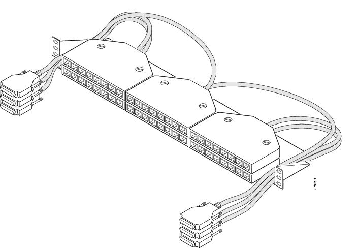
Step 2
a.
Figure A-3 Routing Cables with Molded RJ-45 Ends of Cables Next to Each Other
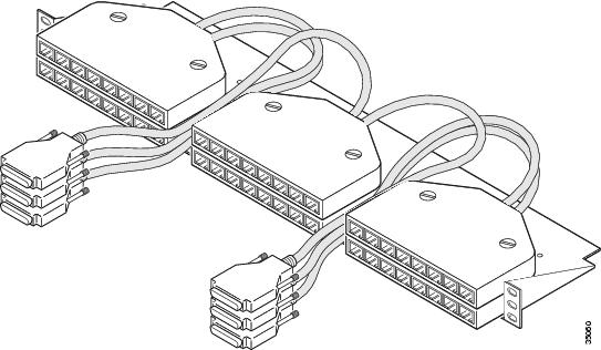
b.
Figure A-4 Routing Cables with Molded RJ-45 Ends of Cables Flush with Bracket Edges
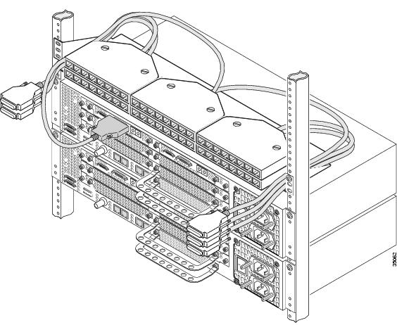
Step 3
Note
Figure A-5 Securing the Cable Bracket to the Rack
Step 4
Step 5
Figure A-6 Connecting the 36-Pin Cable Connector to an 8-Port Interface
CT3 Cable and Port Pinouts
Figure A-7 shows a diagram of the CT3 interface cable assembly. See Table A-2 for the CT3 cable pinouts.
Figure A-7 CT3 Cable Assembly
Table A-2 CT3 Cable Pinouts
1
Rx signal
2
Ground
1
Tx signal
2
Ground
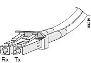
SDH/STM-1 Trunk Card Optical Cables
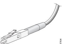
To connect a device to the SDH/STM-1 trunk card, use a standard SFF-LC, SM (single mode), IM (intermediate reach) optical cable with either one duplex connector or two simplex connectors. (See Figure A-8 or Figure A-9.)
Figure A-8 Duplex LC Cable Connector
Figure A-9 Simplex LC Cable Connector
Bantam Jack Port Pinouts
Table A-3 lists the port pinouts for the Bantam jacks.
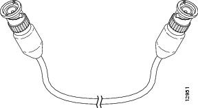
SDH/STM-1 Test Port Adapter Cable
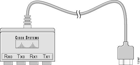
This cable (Cisco part number: 72-2694-01) has a Test Port I/O Connector on one end to attach to the SDH/STM-1 card and a four-port Bantam jack adapter on the other end. Connect a standard Bantam jack test cable to the transmit and receive ports on the adapter. (See Figure A-10.)
Figure A-10 SDH/STM-1 Trunk Card Test Port Adapter Cable