Feedback
Table Of Contents
Installing the SDH/STM-1 Trunk Card
Verifying and Troubleshooting the Installation
Configuring the SDH/STM-1 Trunk Card
Configure the SONET Controller
Configuring Administrative Unit Group (AUG) Mapping under SDH Framing
Configuring a TUG-3 under AU-4 AUG Mapping
Monitor and Drop & Insert Mode
SDH/STM-1 Trunk Card
This chapter describes the SDH/STM-1 trunk card functionality, connectors and LEDs, steps for verifying and troubleshooting your SDH/STM-1 trunk card installation, and card specifications.
This chapter contains the following sections:
•
Installing the SDH/STM-1 Trunk Card
•
Overview
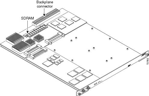
The SDH/STM-1 trunk card (see Figure 4-1) is a high density multiplex/demultiplex trunk card that demultiplexes the SDH/STM-1 trunk down to 1890 DS0 channels at 64 Kbps each. The SDH/STM-1 trunk card allows the Cisco AS5850 to interface to a SDH network at 155 Mbps with a single mode, intermediate reach fiber.
Note
Figure 4-1 shows the SDH/STM-1 trunk card.
Figure 4-1 SDH/STM-1 Trunk Card
Features
•
–
•
The SDH/STM-1 trunk card is a high density multiplex/demultiplex card that takes in an STM-1 (SDH) pipe, used to transport up to 1890 DS0 (30 DS0 per E1) channels in ISDN PRI and E1 R2 configuration and 1953 DS0 (31 DS0 per E1) in SS7 with A-link configuration. In case of NFAS or F-link configuration, between 1890 DS0 to 1953 DS0 channels can be transported. In one direction, a framer removes framing and embedded signaling bits, and the CPU sends the data stream to onboard time-division multiplexing (TDM) resources, which break out each call (DS0) and pass each call to an appropriate call termination resource. Digital calls are terminated onboard the SDH/STM-1 trunk card on HDLC controllers. There are 512 HDLC controllers and each HDLC controller can be used for either a D-channel or one digital call. The SDH/STM-1 trunk card can terminate a maximum of 512 digital calls, less the number of D-channels. For example, with 63 D-channels allocated, 449 digital calls can be terminated. Additional digital calls and analog modem-originated calls are passed over the TDM bus to an available modem resource. The system software controls port and HDLC resource management. In the other direction, the process is reversed.
•
The SDH/STM-1 trunk card supports OIR, a feature that allows you to remove and replace trunk cards in the Cisco AS5850 while the system is operating, without disrupting other cards and their associated calls. If you remove a trunk card while the system is operating, all calls associated with the lines on that card are dropped. Calls being handled by other trunk or modem cards, however, are not affected. For more information, see the "Busyout Command" section.
•
–
–
•
•
•
–
The Cisco AS5850 supports T1, E1, and T3 trunk cards. Table 4-1 shows the possible trunk card configurations:
Note
Interface Specifications
The physical layer interface for the SDH/STM-1 trunk card is synchronous transport module (STM). Each SDH/STM-1 trunk card has two 155.52-Mbps STM physical layer interfaces, but only one interface will be used. Each SDH/STM-1 trunk card has two LC small form-factor type fiber receptacles to allow connection to single-mode optical fiber. Table 4-2 describes the SDH/STM-1 trunk card optical specifications.
The SDH/STM-1 trunk card supports SDH MIB RFC 1595 and DS1 MIB RFC 1406, and provides support for SNMP agent v1 (RFC 1155-1157), and Management Information Base (MIB) II (RFC 1213).
Note
Table 4-2 SDH/STM-1 Trunk Card Optical Specifications
Single-mode intermediate-reach
LC duplex
1261-1360 nm
-8 dBm (max)
-15 dBm (min)
-7 dBm (max)
-28 dBm (min)1
9.3 miles (15 km)
1 bit error rate (BER) = 1*10-10
SONET and SDH Overview
SONET is an American National Standards Institute (ANSI) standard (T1.1051988) for optical digital transmission at hierarchical rates from 51.840 Mbps (STS-1) to 2.488 Gbps (STS-48) and higher. SDH is the international standard for optical digital transmission at hierarchical rates from 155.520 Mbps (STM-1) to 2.488 Gbps (STM-16) and higher.
Both SONET and SDH are based on a structure that has a basic frame and speed. The frame format used by SONET is the synchronous transport signal (STS), with STS-1 being the base level signal at 51.84 Mbps. An STS-1 frame can be carried in an OC-1 signal. The frame format used by SDH is the synchronous transport module (STM), with STM-1 being the base level signal at 155.52 Mbps. An STM-1 frame supports the same payload capacity as an OC-3 signal. The payload of an STM-1 frame can be carried in an OC-3 signal with suitable SDH-to-SONET translation.
Both SONET and SDH have a hierarchy of signaling speeds. Multiple lower-level signals can be multiplexed together to form higher-level signals. For example, three STS-1 signals can be multiplexed together to form an STS-3 signal, and four STM-1 signals multiplexed together form an STM-4 signal.
The International Telecommunications Union Telecommunication Sector (ITU-T) defines a series of SDH transmission rates beginning at 155.520 Mbps. (See Table 4-3.)
Table 4-3 SDH Transmission Rates
STS-3(c)
STM-12
STS-12(c)
STM-4(c)
STS-48(c)
STM-16(c)
1 ANSI-defined SONET specifications
2 Currently supported by the SDH/STM-1 trunk card
Clocking
Each RSC card contains a block of logic referred to as the common logic and system clocks. This block generates the backplane Stratum-4 compliant 4-MHz and 8-kHz clocks used for interface timing and for the TDM bus data movement. The common logic can use a variety of sources to generate system timing, including a T1 or E1 signal, or input from the BNC connector on the RSC front panel. Only one common logic, on one RSC, is active at a time, identified by the CLK LED on the RSC card front panel. The active common logic is user-selectable and is independent from each RSC card. This assures that if you need to replace an RSC, or if the slave RSC becomes the master, clocking remains stable. The selected common logic should not be changed during normal operation unless a hardware failure is suspected or diagnosed in the RSC card.
Each RSC card in the Cisco AS5850 may select from 14 total clock inputs generated from any line card in the chassis or from the RSC front panel BITS input. The default clock source will come from the first trunk card that boots up. If there are no good clocks available, the RSC generates clock for the system.
Note
By using the clock source command and the dial-tdm-clock command the user can select and prioritize the clocking source that will be used by the system.
Note
For more information about these clocking commands, refer to Cisco IOS Dial Technologies Command Reference and Cisco IOS Interface Command Reference. You can access these documents at: Cisco Product Documentation > Cisco IOS version you are using > Configuration Guides and Command References.
LED Indicators
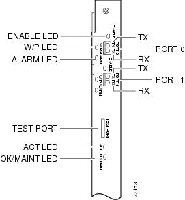
The SDH/STM-1 trunk card front panels are designed with LED indicators (Figure 4-2) to provide trunk card status and port-level monitoring information.
Figure 4-2 SDH/STM-1 Trunk Card LEDs
The two types of LEDs for the SDH/STM-1 trunk cards are:
•
•
All LEDs are visible from the front panel.
Table 4-4 lists the LEDs and their functions.
Table 4-5 SDH/STM-1 Trunk Card LED States
ON
—
OFF
Port up (Active), laser on, working port
ON
—
ON
Port up, port in alarm
OFF
—
OFF
Port inactive
1 The W/P LED is not implemented at this time.
Specifications
Table 4-6 lists the SDH/STM-1 trunk card specifications.
Table 4-6 SDH/STM-1 Trunk Card Specifications
Dimensions H x W x L
15.5 x 1.23 x 19 in. (39.37 x 3.12 x 48.26 cm)
Weight
8 lb (3.6 kg)
Transmission bit rate
155.52 Mbps
Power requirements
-48 VDC at 2 A (power consumption: 3.3 VDC and 5 VDC)
Regulatory compliance and safety1
CFR47 Part 15 (FCC) class B, ICES 003 class B, EN61000-3-2, EN55022 class B,CISPR22 class B, VCCI Class B
1 See also the regulatory compliance and safety document that shipped with your Cisco AS5850.
Installing the SDH/STM-1 Trunk Card
For instructions about installing and removing cards in the Cisco AS5850, see "Replacing or Installing Server Cards."
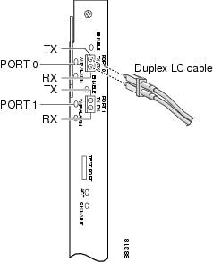
Connecting Trunk Card Cables
The SDH/STM-1 trunk card has two SFF-LC, SM optical connectors.
Follow these steps to connect an SDH/STM-1 trunk card to the network:
Warning
Step 1
Note
Figure 4-3 Connecting the SDH/STM-1 Trunk Card
Step 2
Note
Note
Verifying and Troubleshooting the Installation
When you first power on your Cisco AS5850 universal gateway, all LEDs go on while the system runs a series of diagnostics. After the system passes initial diagnostics, all LEDs go off and then go on again. Table 4-7 provides a quick reference for nominal LED readings for Cisco AS5850 core components. If LED readings vary from those listed, refer to the Cisco AS5850 Universal Gateway Hardware Installation Guide for troubleshooting information.
To complete the installation, verify that the SDH/STM-1 trunk card LEDs operate properly by observing the LED states. (See Table 4-5.)
Configuring the SDH/STM-1 Trunk Card
This section shows how to configure the SDH/STM-1 trunk card. A SONET controller is automatically created when the SDH/STM-1 trunk card is detected by the system. The basic configuration steps include:
•
•
•
Configure the SONET Controller
The following steps will configure the basic SONET controller:
Configuring Administrative Unit Group (AUG) Mapping under SDH Framing
In SDH, there are two possible mapping/multiplexing schemes for most payload types: ANSI and ETSI. The SDH/STM-1 trunk card supports both schemes.
In ANSI mapping, the low order payloads are aggregated into a VC-3 high order path. An AU pointer is added to the VC-3 to create an AU-3 (Administrative Unit type 3). Three such AU-3s are then synchronously multiplexed into an AUG (AU group). The multiplexing scheme is as follows:
VC-3 <-> AU-3 (x3) <-> AUG <-> STM-1
In ETSI mapping, the low order payloads are aggregated into a VC-4 high order path. An AU pointer is added to the VC-4 to create an AU-4 (Administrative Unit type 4). One AU-4 is "multiplexed" into an AUG (AU group), which is to say, the AUG is, in fact, equivalent to an AU-4. The multiplexing scheme is as follows:
TUG-3 (x3) <-> VC-4 <-> AU-4 (x1) <-> STM-1
Configuring a TUG-3 under AU-4 AUG Mapping
Under SDH framing with AUG mapping set to AU-4, the VC-4 high order path comprises three TUG-3s. Each TUG-3 can be configured to carry up to 21 E1s, mapped into VC-12s. The mode of operation of a TUG-3 is not configurable, and defaults to mode c-12.
When you are configuring theSDH/STM-1 trunk card for SDH framing, and have selected au-4 as the mode of operation, you can configure a TUG-3 using the following steps:
Configuring the E1 controller
You can allocate the available channels for channelized E1 in the following ways:
•
•
•
•
Follow these steps to configure an E1 controller:
Note
Note
Verify
To verify controller and path status, enter the show controllers sonet command.
Gateway# sh controllers sonetSONET 3/0 is down.Applique type is Channelized Sonet/SDHClock Source is Internal, AUG mapping is AU4.Medium info:Type: SDH, Line Coding: NRZ, Line Type: Short SMRegenerator Section Status:LOSMultiplex Section Status:Higher Order Path Status:Path# 1 has no defectsLower Order Path Status:VC-12 1/1/1/1 has no defectsVC-12 1/1/1/2 has no defectsVC-12 1/1/1/3 has no defectsVC-12 1/1/2/1 has no defectsVC-12 1/1/2/2 has no defectsVC-12 1/1/2/3 has no defectsVC-12 1/1/3/1 has no defectsVC-12 1/1/3/2 has no defectsVC-12 1/1/3/3 has no defectsVC-12 1/1/4/1 has no defectsVC-12 1/1/4/2 has no defectsVC-12 1/1/4/3 has no defectsVC-12 1/1/5/1 has no defectsVC-12 1/1/5/2 has no defectsVC-12 1/1/5/3 has no defectsVC-12 1/1/6/1 has no defectsVC-12 1/1/6/2 has no defectsVC-12 1/1/6/3 has no defectsVC-12 1/1/7/1 has no defectsVC-12 1/1/7/2 has no defectsVC-12 1/1/7/3 has no defects...VC-12 1/3/5/3 has no defectsVC-12 1/3/6/1 has no defectsVC-12 1/3/6/2 has no defectsVC-12 1/3/6/3 has no defectsVC-12 1/3/7/1 has no defectsVC-12 1/3/7/2 has no defectsVC-12 1/3/7/3 has no defectsData in current interval (20 seconds elapsed):Regenerator Section:0 CVs, 20 ESs, 20 SESs, 0 SEFSsMultiplex Section:0 CVs, 0 ESs, 0 SESs, 0 UASsHigher Order Path:Path# 1: 0 CVs, 0 ESs, 0 SESs, 20 UASsLower Order Path:VC-12 1/1/1/1: 0 CVs, 0 ESs, 0 SESs, 20 UASsVC-12 1/1/1/2: 0 CVs, 0 ESs, 0 SESs, 20 UASsVC-12 1/1/1/3: 0 CVs, 0 ESs, 0 SESs, 20 UASsVC-12 1/1/2/1: 0 CVs, 0 ESs, 0 SESs, 20 UASsVC-12 1/1/2/2: 0 CVs, 0 ESs, 0 SESs, 20 UASsVC-12 1/1/2/3: 0 CVs, 0 ESs, 0 SESs, 20 UASsVC-12 1/1/3/1: 0 CVs, 0 ESs, 0 SESs, 20 UASsVC-12 1/1/3/2: 0 CVs, 0 ESs, 0 SESs, 20 UASsVC-12 1/1/3/3: 0 CVs, 0 ESs, 0 SESs, 20 UASsVC-12 1/1/4/1: 0 CVs, 0 ESs, 0 SESs, 20 UASsVC-12 1/1/4/2: 0 CVs, 0 ESs, 0 SESs, 20 UASsVC-12 1/1/4/3: 0 CVs, 0 ESs, 0 SESs, 20 UASsVC-12 1/1/5/1: 0 CVs, 0 ESs, 0 SESs, 20 UASsVC-12 1/1/5/2: 0 CVs, 0 ESs, 0 SESs, 20 UASsVC-12 1/1/5/3: 0 CVs, 0 ESs, 0 SESs, 20 UASsVC-12 1/1/6/1: 0 CVs, 0 ESs, 0 SESs, 20 UASsVC-12 1/1/6/2: 0 CVs, 0 ESs, 0 SESs, 20 UASsVC-12 1/1/6/3: 0 CVs, 0 ESs, 0 SESs, 20 UASsVC-12 1/1/7/1: 0 CVs, 0 ESs, 0 SESs, 20 UASsVC-12 1/1/7/2: 0 CVs, 0 ESs, 0 SESs, 20 UASsVC-12 1/1/7/3: 0 CVs, 0 ESs, 0 SESs, 20 UASs...VC-12 1/3/5/3: 0 CVs, 0 ESs, 0 SESs, 20 UASsVC-12 1/3/6/1: 0 CVs, 0 ESs, 0 SESs, 20 UASsVC-12 1/3/6/2: 0 CVs, 0 ESs, 0 SESs, 20 UASsVC-12 1/3/6/3: 0 CVs, 0 ESs, 0 SESs, 20 UASsVC-12 1/3/7/1: 0 CVs, 0 ESs, 0 SESs, 20 UASsVC-12 1/3/7/2: 0 CVs, 0 ESs, 0 SESs, 20 UASsVC-12 1/3/7/3: 0 CVs, 0 ESs, 0 SESs, 20 UASsGateway#To troubleshoot your E1 controllers, first check that the configuration is correct. The framing type and line code should match to what the ADM has configured. Then check channel group and PRI-group configurations, especially to verify that the time slots and speeds are what the service provider has specified. At this point, use the show controller e1 command to check for E1 errors. Use the command several times to determine if error counters are increasing, or if the line status is continually changing. If this is occurring, you need to work with the service provider.
To refer VC-12 to the E1 controller mapping to Test port and MGCP endpoints, the following command can be used.
RSC-Slot6#sh controllers sonet 1/0 tabularSONET 1/0 is up.Applique type is Channelized Sonet/SDHClock Source is Internal, AUG mapping is AU4.--------VC-12 1/3/7/3 has no defectsVC-12 to E1 Controller to Port mapping:VC-12 E1(K/L/M) RPMS Trunk/Testport MGCP Endpoint1/1/1/1 1/0.1/1/1 0 11/1/2/1 1/0.1/2/1 1 2--------------------1/3/5/3 1/0.3/5/3 60 611/3/6/3 1/0.3/6/3 61 621/3/7/3 1/0.3/7/3 62 63Using the Test Port
Monitor and Drop & Insert Mode
The Monitor Mode and Drop & Insert Mode is available on the SDH/STM-1 trunk card.
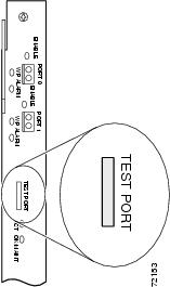
If a controller does not go up, or there are a large number of errors associated with a specific E1 controller, you might be able to determine whether the problem is in the server card or in an external line by using the test port. The test port is located on the front panel of the SDH/STM-1 trunk card.
The test connector allows the connection of an external optical analyzer (for example, an Omniver 718c test device) to monitor an individual circuit in monitor mode. (See Figure 4-4.)
Note
Use the test trunk stm1 command to enable and disable passive monitoring on a specific E1 controller:
Gateway# test trunk STM1 [drop | monitor] [tx | rx] [on | off] E1 controller
Use the show trunk testport command to check which ports are being monitored:
Gateway# show trunk testport
For more information on software commands, refer to the Cisco AS5850 Operations, Administration, Maintenance, and Provisioning Guide, available online at http://www.cisco.com/univercd/cc/td/doc/product/access/acs_serv/as5850/sw_conf/5850oamp/ index.htm.
Test equipment is used to listen to E1 signal on the RX0 jack or / and drop/insert E1 signal on the Tx0 jack during regular operation to detect errors.
Connecting test equipment to the following Bantam jack connectors provides various functions:
•
•
Note
Figure 4-4 SDH/STM-1 Trunk Card Test Port
Warning
Loopback Testing
If there are errors associated with the SONET controller, you can use the loopback command in controller configuration mode to test the controller.
Note
Gateway(config-controller)# loopback [{local | network}]
Options:
•
•