Feedback
Table Of Contents
Setting Up Basic IP Modem Services
Network-Service Considerations
Establishing a Network-Service Definition
Obtaining a New Cisco IOS Version
Backing Up Your AS5800 Configuration
Upgrading the Router-Shelf Software
Upgrading the Router-Shelf Boot Image
Split-Dial-Shelf Configuration
Potential Split-Dial-Shelf Problems
Split-Dial-Shelf Show Commands
Configuring Split-Dial-Shelf Routers
Split-Dial-Shelf Error Messages
Verifying and Troubleshooting Split-Dial-Shelf Installation
Provisioning
This chapter describes basic hardware and service provision considerations such as system environment requirements, physical infrastructure checklists, IP service considerations, and system upgrade procedures for the Cisco AS5800.
For details on the following, refer to the information on preparing for installation in the Cisco AS5800 Access Server Hardware Installation Guide, available online at
http://www.cisco.com/univercd/cc/td/doc/product/access/acs_serv/as5800/hw_inst/•
Safety recommendations
•
•
Note
Setting Up Basic IP Modem Services
This section describes how to set up and provision basic modem IP services using a Cisco AS5800 network access server. It is tailored for network engineers who work with dialup access technologies, and assumes the reader is Cisco certified or familiar with Cisco IOS routers and technologies.
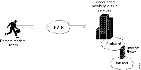
Corporate users and Internet service providers (ISP) install dialup services to facilitate e-mail, e-commerce, and application/database access for employees, roaming sales personnel, household consumers, and students. As a corporate user or ISP, you want to:
•
•
The following section discusses:
•
•
•
Figure 6-1 Business Scenario
Network-Service Considerations
The network-service definition for a corporate user generally differs from that for an ISP, as shown in Table 6-1.
Establishing a Network-Service Definition
Begin your implementation of basic IP UPC services by establishing a network service definition. Use the perspectives described in Table 6-1 preceding and in the following list of design and configuration considerations as a guide. A conservative approach is to project your current deployment and design into a three-month, one-year, and five-year timeline.
Step 1
•
•
•
Step 2
Step 3
•
•
Step 4
•
•
•
•
•
Step 5
•
•
•
•
•
Step 6
Step 7
•
•
•
Step 8
•
•
•
Step 9
Step 10
Step 11
•
•
Step 12
•
•
Step 13
•
•
Step 14
Step 15
Step 16
Step 17
Cisco IOS Upgrades
This section describes Cisco IOS upgrade procedures for the Cisco AS5800. The following tasks are detailed.
•
•
•
•
•
•
•
A Cisco IOS upgrade requires a compatible Cisco IOS image upgrade on both the dial-shelf controller (DSC) cards and router-shelf (RS) components of the system. Two distinct upgrade procedures are necessary, one for each component.
Note
Note
Software Upgrade Requisites
To upgrade a Cisco IOS software image you need the following:
•
•
Memory Requirements
Before installing new software, first determine the amount of available memory in RAM and Flash.
Note
Step 1
AS5800#show versionCisco Internetwork Operating System SoftwareIOS (tm) 5800 Software (C5800-P4-M), Version 12.x...ROM: System Bootstrap, Version 12.xBOOTFLASH: 7200 Software (C7200-BOOT-M), Version 12.x...cisco 7206VXR (NPE400) processor with 253952K/40960K bytes of memory....16384K bytes of Flash PCMCIA card at slot 0 (Sector size 128K).4096K bytes of Flash internal SIMM (Sector size 256K)....AS5800#Step 2
AS5800# show flash-#- ED --type-- -- --- -seek-- nlen -length- -----date/time------ name1 .. image AAD4004B 719C50 25 7314384 May 02 2000 13:55:04 c5800-p4-mz_120-4_XL1.bin9069488 bytes available (7314512 bytes used)Step 3
Obtaining a New Cisco IOS Version
To obtain a recent version of the Cisco IOS software, you need access to the Cisco.com website.
Cisco IOS software is version specific bundled software that includes the following compatible components:
•
•
•
Note
Step 2
Backing Up Your AS5800 Configuration
Cisco recommends backing up all existing Cisco IOS images and configurations from privileged exec mode.
Note
Step 1
AS5800# copy startup-config tftpAddress or name of remote host []? 171.71.219.167Destination filename [startup-config]? AS5800-startup!!3449 bytes copied in 0.136 secsStep 2
AS5800# copy running-config tftpAddress or name of remote host []? 171.71.219.167Destination filename [running-config]? AS5800-running-config!!3312 bytes copied in 0.140 secsStep 3
Router# copy running-configuration start-up configuration
Note
Step 4
AS5800# show bootflash:-#- ED --type-- --crc--- -seek-- nlen -length- -----date/time------ name1 .. image AC05EDDF 37A6B8 22 3384888 Dec 31 1999 18:08:09 c7200-boot-mz.120-4.XEStep 5
AS5800# copy bootflash: tftpSource filename [c]? c7200-boot-mz.120-4.XEAddress or name of remote host []? 171.71.219.167Destination filename [c7200-boot-mz.120-4.XE]?!!!!!!!!!!!!!!!!!!!!!!!!!!!!!!!!!!!!!!!!!!!!!!!!!!!!!!!!!!!!!!!!!!!!!!!!!!!!!!!!!!!!!!!!!! !!!!!!!!!!!!!!!!!!!!!!!!!!!!!!!!!!!!!!!!!!!!!!!!!!!!3384888 bytes copied in 89.920 secs (38032 bytes/sec)Step 6
AS5800# show flash-#- ED --type-- --crc--- -seek-- nlen -length- -----date/time------ name1 .. image AAD4004B 719C50 25 7314384 May 02 2000 13:55:04 c5800-p4-mz_120-4_XL1.binStep 7
AS5800# copy flash tftpSource filename []? c5800-p4-mz_120-4_XL1.binAddress or name of remote host []? 171.71.219.167Destination filename [c5800-p4-mz_120-4_XL1.bin]?!!!!!!!!!!!!!!!!!!!!!!!!!!!!!!!!!!!!!!!!!!!!!!!!!!!!!!!!!!!!!!!!!!!!!!!!!!!!!!!!!!!!!!!!!! !!!!!!!!!!!!!!!!!!!!!!!!!!!!!!!!!!!!!!!!!!!!!!!!!!!!7314384 bytes copied in 218.684 secs (33552 bytes/sec)Step 8
Note
Installing New IOS Software
A Cisco IOS upgrade requires a compatible Cisco IOS image upgrade on both the dial-shelf controller (DSC) cards and router-shelf (RS) components of the system. Two distinct upgrade procedures are necessary, one for each component.
Note
Note
Note
Upgrading the DSC Software
The following procedure outlines commands used to perform a Cisco 5814 dial-shelf controller (DSC) software upgrade from the router shelf.
Step 1
Step 2
AS5800# execute-on slot 12 show bootflash:DA-Slot12#-#- ED --type-- --crc--- -seek-- nlen -length- -----date/time------ name1 .. image BC8CA85F 251C60 26 2169824 Nov 18 1999 22:12:15 dsc-c5800-mz.120-4.XL1.binStep 3
AS5800# execute-on slot 12 delete bootflash:dsc-c5800-mz.120-4.XL1.binDA-Slot12#Delete filename [dsc-c5800-mz.120-4.XL1.bin]?Delete bootflash:dsc-c5800-mz.120-4.XL1.bin? [confirm]AS5800#Step 4
AS5800# execute-on slot 12 squeeze bootflashDA-Slot12#All deleted files will be removed. Continue? [confirm]Squeeze operation may take a while. Continue? [confirm]Squeeze of bootflash completeStep 5
AS5800# execute-on slot 12 show flashDA-Slot12#-#- ED --type-- --crc--- -seek-- nlen -length- -----date/time------ name1 .. image BC8CA85F 231C60 26 2169824 Sep 16 1999 18:10:32 dsc-c5800-mz.120-4.XL1.bin2 .D image 8FDE1F61 45FEC8 18 2286056 Jan 25 2000 18:28:57 dsc-c5800-mz.Jan21
Note
Step 6
AS5800# execute-on slot 12 delete flash:dsc-c5800-mz.120-4.XL1.binDA-Slot12#Delete filename [dsc-c5800-mz.120-4.XL1.bin]?Delete slot0:dsc-c5800-mz.120-4.XL1.bin? [confirm]AS5800#Step 7
AS5800# execute-on slot 12 squeeze flash:DA-Slot12#All deleted files will be removed. Continue? [confirm]Squeeze operation may take a while. Continue? [confirm]Writing sector: 1Squeeze of slot0 completeStep 8
Note
AS5800# copy tftp:dsc-c5800-mz.120-7.T.bin dsc12-slot0Address or name of remote host [171.71.219.167]?Source filename [dsc-c5800-mz.120-7.T.bin ]?Destination filename [dsc12-slot0]?Accessing tftp://171.71.219.167/dsc-c5800-mz.120-7.T.bin ...%Warning: File not a valid executable for this systemAbort Copy? [confirm]nLoading dsc-c5800-mz.120-7.T.bin from 171.71.219.167 (via FastEthernet0/0/0):!!!!!!!!!!!!!!!!!!!!!!!!!!!!!!!!!!!!!!!!!!!!!!!!!!!!!!!!!!The following Warning message appears.
%Warning: File not a valid executable for this systemAbort Copy? [confirm]
Note
Step 9
Step 10
AS5800# execute-on slot 12 copy slot0:dsc-c5800-mz.120-7.T.binbootflash:DA-Slot12#Destination filename [dsc-c5800-mz.120-7.T.bin ]?CCCCCCCCCCCCCCCCCCCCCCCCCCCCCCCCCCCCCCCCCCCCCCCCCCCCCCCCCCCCCCCCCCCCCCCCCCCCCCCCCCCCCCCCCC CCCCCCCCCCCCCCCCCCCCCCCCCCCCCCCCCCCCCCCCCCCCCCCCCCCC2169824 bytes copied in 24.464 secs (90409 bytes/sec)Step 11
Router# execute-on slot 12 reloadStep 12
Note
Upgrading the Router-Shelf Software
The following procedure outlines commands used to perform a Cisco 7206 router-shelf (RS) software upgrade from the router shelf.
Note
Step 1
AS5800# show flash-#- ED --type-- --crc--- -seek-- nlen -length- -----date/time------ name1 .. image AAD4004B 719C50 25 7314384 May 02 2000 13:55:04 c5800-p4-mz_120-4_XL1.bin9069488 bytes available (7314512 bytes used)
Note
Step 2
AS5800# delete slot0:c5800-p4-mz_120-4_XL1.binDelete filename [c5800-p4-mz_120-4_XL1.bin]?Delete slot0:c5800-p4-mz_120-4_XL1.bin? [confirm]Step 3
AS5800# squeeze slot0:All deleted files will be removed. Continue? [confirm]Squeeze operation may take a while. Continue? [confirm]Squeeze of slot0 completeStep 4
Note
AS5800# copy tftp:c5800-p4-mz.120-7.T.bin slot0:Address or name of remote host [171.71.219.167]?Source filename [c5800-p4-mz.120-7.T.bin ]?Destination filename [c5800-p4-mz.120-7.T.bin ]?Accessing tftp://171.71.219.167/c5800-p4-mz.120-7.T.bin ...Loading c5800-p4-mz.120-7.T.bin from 171.71.219.167 (via FastEthernet0/0/0):!!!!!!!!!!!!!!!!!!!!!!!!!!!!!!!!!!!!!!!!!!!!!!!!!!!!!!!!!!!!!!!!!!!!!!!Step 5
Note
Step 6
Router# reload
Upgrading the Router-Shelf Boot Image
The following procedure outlines commands used to perform a Cisco 7206 router-shelf (RS) boot image software upgrade from the router shelf.
Note
Step 1
AS5800# show bootflash-#- ED --type-- --crc--- -seek-- nlen -length- -----date/time------ name1 .. image AC05EDDF 37A6B8 22 3384888 Dec 31 1999 18:08:09 c7200-boot-mz.120-4.XE1 bytes available (3407872 bytes used)Step 2
AS5800# delete bootflash:Delete filename []? c7200-boot-mz.120-4.XEDelete bootflash:c7200-boot-mz.120-4.XE? [confirm]Step 3
AS5800# squeeze bootflash:All deleted files will be removed. Continue? [confirm]Squeeze operation may take a while. Continue? [confirm]Squeeze of bootflash completeStep 4
AS5800# copy tftp bootflash:Address or name of remote host []? 171.71.219.167Source filename []? c7200-boot-mz.120-7.T.binDestination filename [c7200-boot-mz.120-7.T.bin]?Accessing tftp://171.71.219.167/c7200-boot-mz.120-7.T.bin...Loading c7200-boot-mz.120-7.T.bin from 171.71.219.167 (via FastEthernet0/0/0):!!!!!!!!!!!!!!!!!!!!!!!!!!!!!!!!!!!!!!!!!!!!!!!!!!!!!!!!!!!!!!!!!!!!!!!!!!!!!!!!!!!![OK - 3384888/6769664 bytes]3384888 bytes copied in 65.112 secs (52075 bytes/sec)
Software Upgrade Verification
Perform the following steps to verify that the router shelf and DSCs are running new Cisco IOS images, and the Bootflash is running a new boot image.
Step 1
AS5800# execute-on slot 12 show versionDA-Slot12>Cisco Internetwork Operating System SoftwareIOS (tm) 5800 Software (C5800-DSC-M), Version 12.xTAC:Home:SW:IOS:Specials for infoCopyright (c) 1986-1999 by cisco Systems, Inc.Compiled Thu 12-Aug-99 18:48 by ayehImage text-base: 0x600088F0, data-base: 0x60520000ROM: System Bootstrap, Version x AA, ROM: 5800 Software (C5800-DSC-M),Version 12.xDA-Slot12 uptime is 41 minutesSystem returned to ROM by reloadSystem image file is "slot0:dsc-c5800-mz.120-7.T.bin "Router# execute-on slot 13 show version (IF APPLICABLE)Step 2
AS5800# show versionCisco Internetwork Operating System SoftwareIOS (tm) 5800 Software (C5800-P4-M), Version 12.x, TAC:Home:SW:IOS:Specials for infoCopyright (c) 1986-1999 by cisco Systems, Inc.Compiled Thu 12-Aug-99 13:16 by ayehImage text-base: 0x60008900, data-base: 0x611A6000ROM: System Bootstrap, Version 12.xBOOTFLASH: 7200 Software (C7200-BOOT-M), Version 12.xdoc-rtr58-01 uptime is 9 minutesSystem returned to ROM by reload at 16:04:24 CST Fri Jun 9 2000System restarted at 16:05:39 CST Fri Jun 9 2000System image file is "slot0:c5800-p4-mz.120-7.T.bin"Step 3
AS5800#sh bootflash:-#- ED --type-- --crc--- -seek-- nlen -length- -----date/time------ name1 .. image AC05EDDF 37A6B8 22 3384888 Jun 12 200014:00:23 c7200-boot-mz.120-7.T.bin22856 bytes available (3385016 bytes used)
Modem Upgrading
Compatible modem firmware is included in each Cisco IOS bundled software version and upgraded as part of the installation process.
Note
Modem Upgrades
This section describes basic debugging and modem commands used for upgrading modem module firmware as well as modem activation considerations. The show modem version command output is displayed to verify a successful download.
Debugging a Modem
Use the following commands for debugging a modem or group of modems.
From the Cisco IOS privileged mode AS5800-1# .
•
debug modem oob shelf/slot/port group group_number•
debug csm shelf/slot/port group group_number•
debug modem trace {normal | abnormal | all} shelf/slot/port group group_numberUpgrading Modem Firmware
Each modem card installed in your Cisco AS5800 access server contains 12 MICA modems, each with six modem SIMMs. This allows you to upgrade firmware for each group of six modem SIMMs.
The default firmware image is loaded on the modem card during system boot-up. Normally, you do not need to change the firmware image; however, you can override the default image with another firmware image.
A valid pool range must exist (that is, the pool-range modem pool configuration command must have been configured) for modem overrides to occur. Modem pooling allows you to define, select, and use separate modem pools within a single access server or router to enable different dial-in services for different customers. In this case, the modem pool specifies which modems are loaded with the new firmware image.
The specified firmware image is loaded on every modem for every slot specified in the pool range. If the modem is busy, the firmware change is deferred until the modem is available. When the modem is available, the firmware change takes place immediately.If you specify a firmware image that does not exist, the information is stored so that, in the event that the modem card is updated with that firmware image, it will be loaded when the modem card image boots.
At boot-up time, the default firmware image is loaded first. If there is a firmware image specified by the firmware command, it is then loaded onto the modem card.
Table 6-2 lists modem firmware upgrade commands to override the default modem firmware image with another specified firmware image.
To deactivate a modem command, type no before the command:
AS5800-1(config)# modem-pool testAS5800-1(config-modem-pool)# no firmware 2.2.2.2To verify that a download has succeeded, use the show modem version command.
AS5800-1> show modem versionModem Range Module Firmware Rev1/6/00 1/6/05 0 2.2.2.21/6/06 1/6/11 1 2.2.2.21/6/12 1/6/17 2 2.2.2.21/6/18 1/6/23 3 2.2.2.21/6/24 1/6/29 4 2.2.2.21/6/30 1/6/35 5 2.2.2.21/6/36 1/6/41 6 2.2.1.71/6/42 1/6/47 7 2.2.1.71/6/48 1/6/53 8 2.2.1.71/6/54 1/6/59 9 2.2.1.71/6/60 1/6/65 10 2.2.1.71/6/66 1/6/71 11 2.2.1.7Modem board HW version info:Modem Range: 1/6/00 1/6/05 Modem Module: 0Manufacture Cookie Info:EEPROM Type 0x0101, EEPROM Version 0x01, Board ID 0x06,Board Hardware Version 1.0, Item Number 73-2522-2,Board Revision 051, Serial Number 06298557,PLD/ISP Version 255.255, Manufacture Date 17-Jul-1997.Modem Range: 1/6/06 1/6/11 Modem Module: 1Manufacture Cookie Info:EEPROM Type 0x0101, EEPROM Version 0x01, Board ID 0x06,Board Hardware Version 1.0, Item Number 73-2522-2,Board Revision 051, Serial Number 06298553,PLD/ISP Version 255.255, Manufacture Date 17-Jul-1997.Modem Range: 1/6/12 1/6/17 Modem Module: 2Manufacture Cookie Info:EEPROM Type 0x0101, EEPROM Version 0x01, Board ID 0x06,Board Hardware Version 1.0, Item Number 73-2522-2,Board Revision 051, Serial Number 06298017,PLD/ISP Version 255.255, Manufacture Date 17-Jul-1997.Modem Range: 1/6/18 1/6/23 Modem Module: 3Manufacture Cookie Info:EEPROM Type 0x0101, EEPROM Version 0x01, Board ID 0x06,Board Hardware Version 1.0, Item Number 73-2522-2,Board Revision 051, Serial Number 06298019,PLD/ISP Version 255.255, Manufacture Date 17-Jul-1997.Modem Range: 1/6/24 1/6/29 Modem Module: 4Manufacture Cookie Info:EEPROM Type 0x0101, EEPROM Version 0x01, Board ID 0x06,Board Hardware Version 1.0, Item Number 73-2522-2,Board Revision 051, Serial Number 06298200,PLD/ISP Version 255.255, Manufacture Date 17-Jul-1997.Modem Range: 1/6/30 1/6/35 Modem Module: 5Manufacture Cookie Info:EEPROM Type 0x0101, EEPROM Version 0x01, Board ID 0x06,Board Hardware Version 1.0, Item Number 73-2522-2,Board Revision 051, Serial Number 06298590,PLD/ISP Version 255.255, Manufacture Date 17-Jul-1997.Modem Range: 1/6/36 1/6/41 Modem Module: 6Manufacture Cookie Info:EEPROM Type 0x0101, EEPROM Version 0x01, Board ID 0x06,Board Hardware Version 1.0, Item Number 73-2522-2,Board Revision 051, Serial Number 06298446,PLD/ISP Version 255.255, Manufacture Date 17-Jul-1997.Modem Range: 1/6/42 1/6/47 Modem Module: 7Manufacture Cookie Info:EEPROM Type 0x0101, EEPROM Version 0x01, Board ID 0x06,Board Hardware Version 1.0, Item Number 73-2522-2,Board Revision 051, Serial Number 06298593,PLD/ISP Version 255.255, Manufacture Date 17-Jul-1997.Modem Range: 1/6/48 1/6/53 Modem Module: 8Manufacture Cookie Info:EEPROM Type 0x0101, EEPROM Version 0x01, Board ID 0x06,Board Hardware Version 1.0, Item Number 73-2522-2,Board Revision 051, Serial Number 06298233,PLD/ISP Version 255.255, Manufacture Date 17-Jul-1997.Modem Range: 1/6/54 1/6/59 Modem Module: 9Manufacture Cookie Info:EEPROM Type 0x0101, EEPROM Version 0x01, Board ID 0x06,Board Hardware Version 1.0, Item Number 73-2522-2,Board Revision 051, Serial Number 06298309,PLD/ISP Version 255.255, Manufacture Date 17-Jul-1997.Modem Range: 1/6/60 1/6/65 Modem Module: 10Manufacture Cookie Info:EEPROM Type 0x0101, EEPROM Version 0x01, Board ID 0x06,Board Hardware Version 1.0, Item Number 73-2522-2,Board Revision 051, Serial Number 06297954,PLD/ISP Version 255.255, Manufacture Date 17-Jul-1997.Modem Range: 1/6/66 1/6/71 Modem Module: 11Manufacture Cookie Info:EEPROM Type 0x0101, EEPROM Version 0x01, Board ID 0x06,Board Hardware Version 1.0, Item Number 73-2522-2,Board Revision 051, Serial Number 06298008,PLD/ISP Version 255.255, Manufacture Date 17-Jul-1997.Modem Operation at Bootup
When the Cisco 7206 router shelf boots up and parses its NVRAM, the modem cards will not be up. As a result, the override firmware name is stored in the modem pool structures and no action is taken.
When a modem card becomes active, it sends a startup message to the router shelf. The router shelf then triggers a search in the various modem pools to see if any modem modules on the modem card have a specified firmware override. If yes, the firmware override request is relayed to the modem card, which will load the specified override firmware image on the indicated modem modules.
As a result, the modem modules that are destined to run an override firmware image will experience two firmware downloads at bootup time. The default modem firmware image is loaded first, followed by the override modem firmware image.
Error messages result if the following circumstances exist:
•
•
•
•
Split Dial Shelves
The split mode is intended to support two router shelves connected to a single dial shelf. To use this arrangement as intended, both router shelves need a split dial shelf configured. However, a second router is not required; a single router can run in split mode with all slots owned by that router.
Split-Dial-Shelf Configuration
Split-dial-shelf configuration is implemented by connecting two router shelves to a single dial shelf. You allocate the slots in the dial shelf between the two router shelves to achieve the desired configuration. The two router shelves are configured to run in split mode by a new top-level router configuration command:
dial-shelf split slots {slot-numbers}
where slot-numbers is a list of the dial-shelf slot numbers (from 0 to 11) that the router owns, with the slot numbers separated by spaces. Slot ownership for each of the two router shelves is configured individually using the dial-shelf split slots command.
•
•
•
When you configure a Cisco AS5800 to operate in split mode, it is the same as having two Cisco AS5800s, each having a separate set of feature boards assigned to its router that happen to be sharing a single dial shelf. Modem pooling, for example, is the same as if you had two separate Cisco AS5800s. Router shelf 1 has a modem pool that consists of all the modem cards that reside in slots owned by router shelf 1. The same situation applies to router shelf 2.
Changing to Split Mode
This section describes the procedure required to transition a router from normal mode to split mode, and change the set of slots a router owns while it is in split mode. The process of switching the ownership of a slot from one router to the other is potentially disruptive. When a feature board is restarted, all calls through that card are lost. Therefore, a router shelf cannot take over a slot until ownership is relinquished by the router that currently claims ownership, either by reconfiguring the router or disconnecting that router or its associated DSC.
The dial shelf is split by dividing the ownership of the feature boards between the two router shelves. You must configure the division of the dial-shelf slots between the two router shelves so that each router controls an appropriate mix of trunk and modem cards. Each router shelf controls its set of feature boards as if those were the only boards present. There is no interaction between feature boards owned by either router.
Split mode is entered when the dial-shelf split slots command is parsed on the router shelf. This can occur when the router is starting up and parsing the stored configuration or when the command is entered when the router is already up. On parsing the dial-shelf split slots command, the router frees any resources associated with cards in the slots that it no longer owns, as specified by exclusion of slot numbers from the slot-numbers argument. The router should be in the same state as if the card had been removed from the slot; all calls through that card will be terminated. The configured router then informs its connected DSCs that it is in split mode, and which slots it claims to own.
In split mode, a router shelf uses only half of the 1,792 available TDM timeslots. (See the "TDM Resource Allocation" section.) If a dial-shelf split slots command is entered when the calls using timeslots exceed the number that would be available to the router in split mode, the command is rejected. (This should occur only when a change to split mode is attempted where the dial shelf has more than 896 calls in progress, or more than half of the 1,792 available timeslots. Otherwise, a transition from normal mode to split mode can be made without disturbing the cards in the slots that remain owned, and calls going through those cards will stay up.)
TDM Resource Allocation
Trunk cards and modem cards are tied together across a time-division multiplexing (TDM) bus on the dial-shelf backplane. Timeslots for the TDM bus are allocated by the router shelf on a call-by-call basis. This is implemented by initializing a queue at start-up with one element for each usable timeslot (currently 14*128 = 1,792 timeslots are used). Timeslots for a call are allocated from the front of the queue and replaced at the end of the queue when the call is completed. For split-dial-shelf operation, timeslots are added to the queue dynamically, as needed. When a TDM slot is required and the queue is empty, a chunk of TDM slots is allocated to the queue.
In normal mode, the router shelf connected to the DSC in slot 12 allocates timeslots starting from 0 going up, and the router shelf connected to the DSC in slot 13 allocates timeslots starting from 1,791 going down. For split-dial-shelf operation each router is assigned half of the usable set of timeslots. The router shelf connected to the DSC in slot 12 controls the first half of the timeslots (0 to 895). The router shelf connected to the DSC in slot 13 controls the second half of the timeslots (896 to 1791).
Transition Procedure for Split Mode
To transition from normal mode to split mode, complete the following steps:
Step 1
Having the same version of Cisco IOS software running on both DSCs and both router shelves is not mandatory; however, it is a good idea. There is no automatic check to ensure that the versions are the same.
Step 2
The entire procedure for transitioning from normal mode to split mode should require approximately one hour if the hardware is already installed.
Step 3
Step 4
Enter the dial-shelf split slots {slot-numbers} command, specifying the slot numbers that are to be owned by the existing router shelf.
Step 5
Enter the dial-shelf split slots {slot-numbers} command, specifying the slot numbers that are to be owned by the new router shelf. Do not specify any of the slot numbers that you specified in Step 4. The range of valid slot numbers is 0 to 11.
Step 6
Step 7
Step 8
Enter the show dial-shelf command for each router. This command has been extended so that the response indicates that the router shelf is running in split mode, and which slots the router shelf owns. The status of any cards in any owned slots is shown, just as they are in the present show dial-shelf command.
Step 9
Changing Slot Sets
You can change the sets of slots owned by the two router shelves while they are in split mode. First remove slots from the set owned by one router, then add them to the slot set owned by the other router. The changed slot-set information is sent to the respective DSCs, and the DSCs determine which slots have been removed and which added. Moving a slot in this manner will disconnect all calls that were going through the card in that slot.
To move a slot from one router shelf's control to the others, first modify the router releasing the slot by entering the dial-shelf split slots remove command specifying the slot numbers to be released. The released slots can then be added to the slot set of the other router by entering the dial-shelf split slots command including the new slot numbers.
When a slot is removed, the router shelf that is losing the slot frees any resources and clears any state associated with the card in the slot it is relinquishing. The DSC reconfigures its hub to ignore traffic from that slot, and if there is a card in the slot it will be reset. This ensures that the card frees up any TDM resources it might be using, and allows it to restart under control of the router shelf that is subsequently configured to own the slot.
When a slot is added, if there are no configuration conflicts, and there is a card present in the added slot, a dial-shelf OIR insertion event is sent to the router shelf. The router shelf processes the event as a normal event. The card in the added slot is reset by the DSC to ensure a clean state, and the card downloads its image from the router shelf that now owns it. If the other router shelf (and the other DSC) claim ownership of the same slot, the command adding the slot should be rejected. However, should a configuration conflict exist, error messages are sent to both routers. The card is not reset until one of the other router shelves and its DSC stop claiming ownership of the slot. Normally this will not happen until you issue a dial-shelf split slots remove command surrendering the ownership claim on the slot by one of the routers.
Leaving Split Mode
Split mode is exited when the dial-shelf configuration is changed by a no dial-shelf split slots command. When the split dial-shelf line is removed, the router shelf will start using all of the TDM timeslots. Feature boards that were not owned in split mode and are not owned by the other router will be reset. Cards in slots that are owned by the other router will be reset, but only after the other DSC has been removed or is no longer claiming the slots. The split-dial-shelf configuration should not be removed while the second router shelf is still connected to the dial shelf.
When a router configured in split mode fails, all calls associated with the failed router are lost. Users cannot connect back in until the failed router recovers and is available to accept new incoming calls. However, the other split mode router shelf will continue to operate normally.
Potential Split-Dial-Shelf Problems
The system will behave as configured as soon as the configuration is changed. The exception is when there is a misconfiguration, such as when one router is configured in split mode and the other router is configured in normal mode, or when both routers are configured in split mode and both claim ownership of the same slots.
Problems can arise if one of the two routers connected to a dial shelf is not configured in split mode, or if both are configured in split mode and both claim ownership of the same slots. If the state of the second router is known when the dial-shelf split slots command is entered and the command would result in a conflict, the command is rejected.
If a conflict in slot ownership does arise, both routers receive warning messages until the conflict is resolved. Any card in a slot that is claimed by both routers remains under the control of the router that claimed it first, until you resolve the conflict by correcting the configuration of one or both routers.
Note that there can be slots that are not owned by either router (orphan slots). Cards in orphan slots cannot boot up until one of the two routers claims ownership of the slot, because neither DSC will download bootstrap images to cards in orphan slots.
Split-Dial-Shelf Show Commands
In normal mode, all show commands look and behave as they do in the current system. In split mode, most show commands look and behave as they would in the current system if there were no cards in the slots for which the other router has configured ownership. This is consistent with the view of a split-dial-shelf configuration being basically two separate Cisco AS5800 universal access servers. A router shelf cannot manage or even recognize cards in slots that it does not own. For example, DSIP console and execute-on commands work only in owned slots.
There are, however, the following exceptions:
•
•
When in split mode, the show dial-shelf output is extended. For example:
5800# show dial-shelfSystem is in split dial shelf mode.Slots owned: 0 2 3 4 5 6 (connected to DSC in slot 13)Slot Board CPU DRAM I/O Memory State ElapsedType Util Total (free) Total (free) Time0 CE1 0%/0% 21341728( 87%) 8388608( 45%) Up 01:11:372 CE1 0%/0% 21341728( 87%) 8388608( 45%) Up 01:11:374 Modem(HMM) 20%/20% 6661664( 47%) 6291456( 33%) Up 01:11:375 Modem(DMM) 0%/0% 6661664( 31%) 6291456( 32%) Up 01:11:376 Modem(DMM) 0%/0% 6661664( 31%) 6291456( 32%) Up 01:11:3713 DSC 0%/0% 20451808( 91%) 8388608( 66%) Up 01:16:31Dial shelf set for auto bootNote that only the first two lines of output are new. The remaining information is exactly the same as what would currently be displayed if there were no cards in the slots that are not owned (1 and 7 to 12).
•
5800# show dial-shelf splitSystem is in split dial shelf mode, connected to DSC in slot 13.Slots owned: 0 2 3 4 5 6Non owned slots:Slot Board Type1 CE17 Modem(DMM)8 Modem(DMM)9 Modem(DMM)10 Slot Empty11 Slot Empty12 DSC
Note
•
Managing a Split Dial Shelf
If you are installing split-dial-shelf systems, a system controller is available that provides a single system view of multiple POPs. The system controller for the Cisco AS5800 includes the Cisco 3640 router running Cisco IOS software. The system controller can be installed at a remote facility so that you can access multiple systems through a console port or Web interface.
There are no new Management Information Bases (MIBs) or MIB variables required for the split-dial-shelf configuration. A split dial shelf appears to Simple Network Management Protocol (SNMP) management applications as two separate Cisco AS5800s. You cannot use one console to manage the whole system—you must have a console session for each router shelf (two console sessions) to configure each split. The system controller must manage a split-dial-shelf configuration as two separate Cisco AS5800 universal access servers.
The normal mode configuration of the Cisco AS5800 requires the dial-shelf and router-shelf IDs to be different. In a split system, four unique shelf IDs are desirable; one for each router shelf and one for each of the slot sets. However, a split system will function satisfactorily if the router-shelf IDs are the same. If a system controller is used to manage a split-dial-shelf configuration, then the two routers must have distinct shelf IDs, just as they must when each router has its own dial shelf.
You can download software configurations to any Cisco AS5800 using SNMP or a Telnet connection. The system controller also provides performance monitoring and accounting data collection and logging.
In addition to the system controller, a network management system with a graphical user interface (GUI) runs on a UNIX SPARC station and includes a database management system, polling engine, trap management, and map integration.
Configuring Split-Dial-Shelf Routers
To configure a router for split-dial-shelf operation, use the following commands in global configuration mode 5800(config)#
dial-shelf split slots {slot_numbers}Normal mode: This command changes the router shelf to split mode with ownership of the slots listed.
In case of conflicting slot assignments, the command is rejected and a warning message is issued. Issue a show dial-shelf split slots command to the other router shelf to display its list of owned dial-shelf slots.
OIR events on all slots are detected by both DSCs and added to the list of feature boards physically present in the dial shelf. However, OIR event processing is done only for assigned slots.
Split mode: This command adds the dial-shelf slots listed to the router shelf's list of owned slots.
show dial-shelf splitNormal mode: This command is invalid.
Split mode: This command displays the slots assigned to each of the router shelves and the corresponding feature boards in orphan slots (slots not currently assigned to either router).
dial-shelf split slots noneNormal mode: This command puts the router shelf in split mode; however, it does not assign ownership of any dial-shelf slots.
To prevent accidentally entering the dial-shelf split slots command, at least one valid dial-shelf slot number (0-11) or the keyword none must be specified.
If the dial-shelf split slots command is entered in normal mode without valid slot numbers or the keyword none, the command is rejected.
Split mode: This command will change dial-shelf slot ownership. The router will no longer have ownership of any dial-shelf slots.
no dial-shelf split slotsNormal mode: This command has no effect. If the router shelf is in normal mode, it stays that way.
Split mode: This command changes the router shelf to normal mode if it is in split mode, and the other router shelf has already relinquished control of all dial-shelf slots or is switched off.
dial-shelf split slots {slot_numbers}Normal mode: This command changes the router shelf to split mode with ownership of the slots listed. Valid slot numbers are 0 through 11.
–
–
Split mode: This command adds the dial-shelf slots listed to the router shelf's list of owned dial-shelf slots. The effect of multiple commands is cumulative.
dial-shelf split slots remove {slot_numbers}Normal mode: This command has no effect.
Split mode: This command removes the dial-shelf slots listed from the router shelf's list of owned dial-shelf slots. The effect of multiple commands is cumulative.
Split-Dial-Shelf Error Messages
New error messages for various split-dial-shelf conditions include:
Duplicate priority clock source configured on other router shelf.Explanation The configuration commands for the master clock specify the clock sources and a priority for each source. Together, these commands define a prioritized list of the clock sources used to generate the master clock. This list, configured on the router shelf, is passed to and stored by the DSC providing the active clock. In the event of failure of the highest priority clock source, the DSC switches to the source with the next highest priority.
With a split dial shelf, clock sources can be configured on either of the router shelves from the slots that each shelf owns. All valid clock source configurations are known to the DSC providing the clock, including the clock sources configured on the other router or DSC.
This error condition results when a clock source input on one router is configured to have the same priority as one configured on the other router. The original configuration command is not rejected; however, these error messages are issued to both routers. The two inputs, with identical priorities, both go into the ordered list of clock sources, but the one received first by the DSC providing the active clock is assigned a higher priority.Action Reconfigure the clock sources on the two routers so that they have different priorities.
Other router shelf is in split mode when this one is not.Explanation Split mode is intended to support two router shelves connected to a single dial shelf. To use this arrangement, both connected router shelves should be configured for split dial shelves. Problems can arise if two routers are connected to the dial shelf, but one router is not configured in split mode.
Action Issue a dial-shelf split slots command to this router or a no-dial-shelf split slots command to the other router.
Other router shelf is not in split mode when this one is.Explanation Split mode is intended to support two router shelves connected to a single dial shelf. To use this arrangement, both connected router shelves should be configured for split dial shelves. Problems can arise if two routers are connected to the dial shelf, but one router is not configured in split mode.
Action Issue a dial-shelf split slots command to this router or a no-dial-shelf split slots command to the other router.
 Other router shelf has overlapping slot ownership specified in its split dial shelf
configuration.
Explanation Each router shelf connects to one of the DSCs in the dial shelf. The dial-shelf feature boards are divided between the two router shelves. Each router controls its own set of feature boards as if those were the only boards present. There is no interaction between the routers or between feature boards owned by one router and feature boards owned by the other router.
This error message indicates that both routers are configured in split mode, but there is an overlap in the set of slots each router claims. While the conflict in slot ownership continues, both router shelves will periodically receive this error message.Action Correct the configuration of one of the routers by issuing a dial-shelf split slots command with a list of slot numbers that does not include the slot that is reporting as having overlapping ownership. You must configure the division of the dial-shelf slots between the two router shelves so that each router controls an appropriate mix of trunk and modem cards. Any card in a slot that is claimed by both routers remains under the control of the router that claimed it first until you resolve the conflict by correcting the configuration.
Verifying and Troubleshooting Split-Dial-Shelf Installation
Your Cisco 7206 router went through extensive testing before leaving the factory. However, if you encounter problems starting the routers, do the following:
•
http://www.cisco.com/univercd/cc/td/doc/product/core/7206/•
http://www.cisco.com/univercd/cc/td/doc/product/core/7200vx/If you are unable to solve the problem, contact a customer service representative for assistance and further instructions. Be prepared to provide the representative with the following information:
•
•
•
•
•
•
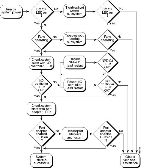
Figure 6-2 shows the general troubleshooting strategy for Cisco 7206 routers. Refer to this chart to isolate problems to a specific subsystem; then attempt to resolve the problem.
Figure 6-2 Troubleshooting Strategy for Start-Up Problems
Router-Shelf Redundancy
When an active router shelf in a Cisco AS5800 loses communication with the dial shelf, a backup router shelf can be automatically invoked to take over dial-shelf resources controlled by the lost router shelf. This backup method, called redundancy, is provided on the Cisco AS5800 to prevent a single point of failure, subsequent downtime, and user intervention to resolve unrecoverable hardware faults.
Router-shelf redundancy uses a second router shelf that automatically assumes resource responsibility (dial-shelf card and traffic control) of the primary, or active router, if it fails. This disruptive failover makes no attempt to retain established calls on the failed router. All calls are dropped when dial-shelf cards, controlled by the failing router, are automatically restarted by the secondary or backup router, which becomes the controlling router after restart.
Failover Operation
Redundancy on a Cisco AS5800 is two router shelves connected, in parallel, to a single dial shelf (as in split-dial-shelf mode), except only one router is active, or engaged, at any given time. Each router shelf contains user specific configurations for normal mode operations, as opposed to split mode. The active router controls all the dial-shelf cards, while the secondary router functions purely as a standby backup. In the event the active router fails, all dial-shelf cards are restarted by the backup router that automatically assumes active router functionality.
External interfaces do not share the same IP address between redundant routers or duplicate IP address errors occur. One (active) router shelf maintains control of dial-shelf cards at a time. However unsuccessful, it does not interfere with the operation of the primary active router. If the active router shelf crashes, the link between it and it's DSC will go down, relinquishing control of all dial-shelf cards to the other DSC which is connected to the secondary or backup router shelf. This surviving router shelf restarts the cards and commences normal operations. If the router shelf that crashed recovers, or is restarted, it will not regain control of the cards, but becomes the backup, serving as the standby router shelf for the new active router, should it fail.
Note
Load-Sharing
There is no load sharing between routers. Calls can not be routed through the active and backup routers simultaneously. Consequently, you cannot split the load between the routers to reduce granularity of failure, or the number of calls that are lost, when a router crashes. Conversely, failover conditions, that would otherwise occur, such as overwhelming traffic volume on the surviving router after failover, under load sharing, will not degrade service.
Hitless Redundancy
Hitless redundancy is not supported. When a router-shelf failover occurs, all calls associated with that router shelf are lost. Cisco AS5800 redundancy ensures that resources (particularly trunk lines) do not remain unusable while the controlling router is down.
Network Management
Redundancy management via SNMP is not supported. However, an SNMP trap will be issued by the backup router when the router failover event occurs. The trap "ccrSwitchStatusChange" defined in the CISCO-C8500-REDUNDANCY-MIB as well as the SNMP variables "ccrCpuMode" and "ccrCpuStatus" are used for issuing a failover.
Failover Performance
Enabling failover has no significant (greater than 1%) impact on system performance, both before and after failover has occurred. With a redundant router, of the same model as the active router, acting purely as a standby, the load capacity threshold is unchanged, thereby not affecting performance.
External Services
A single active router is conceptually simpler, and makes it easier to support failover when dealing with external servers, such as signalling controllers for RPMS server, SS7.
Note
SS7 Setup
In an SS7 environment, call signalling comes via an external SC2200 rather than directly from the switch over the trunk line (as for CAS and ISDN). After a switchover has occurred, both routers must be connected to the SC2200. Use SS7's redundant link manager (RLM) to provide redundant links between a single router and the signalling controller. Configure RLM links from both the active and standby routers so a change of routers will look like a change from one redundant link to another.
Configuring Redundancy
Router-shelf failover is a simple configuration command on the two router shelves in split-dial-shelf configuration mode. The command is issued in "redundancy" configuration submode:
router(config)# redundancyrouter(config-r)# failover group-number <group-code>This command must be configured on both routers. The parameter group-code is used by the system controller and must be the same for both routers forming the redundant pair. It identifies both routers as the same set of dial-shelf resources.
For successful failover to occur, both router-shelf configurations need to be synchronized. Configure each router separately, as active and backup, respectively, with the same configuration, except for the IP address on egress interfaces.
Note
Redundancy Show Commands
The show redundancy command indicates when failover is enabled. The show redundancy history command logs failover events (where the router has changed from ACTIVE to BACKUP or vice-versa).