Feedback
Table Of Contents
Cisco AS5800 Functional Profile
Network Topology and Equipment Selection
Configuration Design Parameters
Cisco IOS Software Fundamentals
Setup-Script Initial Configuration
Deployment and Operation Strategy
Introduction
The Cisco AS5800 universal access server is the latest entry into Cisco's award-winning AS5x00 series of universal access servers, and provides the highest concentration of modem and integrated services digital network (ISDN) terminations available in a single remote access concentrator product. The Cisco AS5800 is specifically designed to meet the demands of large service providers such as post, telephone, and telegraphs (PTTs), regional Bell operating companies (RBOCs), interexchange carriers (IXCs), and large Internet service providers (ISPs). The Cisco AS5800 complies with Network Equipment-Building System (NEBS) Level 3 requirements as defined by Telcordia Technologies SR-3580, and European requirements are defined by the European Telecommunication Standards Institute (ETSI). Cisco offers a full spectrum of lifecycle-focused support solutions that are complementary to the Cisco AS5800. Further, the Cisco AS5800 voice gateway enables highly scalable deployment of toll-quality voice and fax service over packet networks.
This introductory chapter provides a brief profile and review of the Cisco AS5800 hardware components and functionality, signal and data throughput logic, access server management flow, and Cisco IOS software, as well as an information map to this guide.
Cisco AS5800 Functional Profile
The Cisco AS5800 is a high-density, ISDN and modem WAN aggregation system that provides both digital and analog call termination. It is intended to be used in service-provider dial point-of-presence (PoP) or centralized-enterprise dial environments. The dial-shelf feature cards and the host router shelf communicate over a nonblocking interconnect that supports 100-Mbps full-duplex service.
The Cisco AS5800 supports high density dial aggregation and integrates with Cisco AS5200 and Cisco AS5300 access servers for scaling your service provider network. The Cisco AS5800 also supports high availability of service through online insertion and removal (OIR) capabilities, and redundant power supplies that are hot swappable. All active components within the dial-shelf chassis support OIR, which allows components to be removed or replaced while the system is powered on. Feature cards can be busied-out through the software to avoid loss of calls.
The Cisco AS5800 includes a Cisco 5814 dial shelf and a Cisco 7206 router shelf. If you are installing multiple access servers, a system controller is available, which provides a "single system" view of multiple POPs.
The system controller for the Cisco AS5800 includes the Cisco 3640 router running Cisco IOS software. The system controller can be installed at a remote facility so that you can access multiple systems through a console port or Web interface. It is also possible to download software configurations to any Cisco AS5800 using Simple Network Management Protocol (SNMP) or a Telnet connection using the TFTP protocols. The system controller also provides performance monitoring and accounting data collection and logging.
In addition to the system controller, a network management system (CiscoWorks) with a graphical user interface (GUI) runs on a UNIX SPARC station and includes a database management system, polling engine, trap management, and map integration.
The dial shelf contains ingress interfaces (CT1/CE1/PRI) that terminate ISDN and modem calls, and break out individual calls (DS0s) from the appropriate telco services. Digital or ISDN calls are terminated onboard the trunk card HDLC controllers, and analog calls are sent to modem resources on the modem cards. As a result, any DS0 can be mapped to any HDLC controller or modem module.You can install multiple ingress interface cards of similar or different types. This enables you to configure your systems as fully operative, port redundant, or card redundant, depending on your needs.
Trunk cards and modem cards are tied together across a time division multiplexing (TDM) bus on the dial-shelf backplane. The backplane TDM bus transmits and receives PCM-encoded analog data to and from the modem cards. Then the dial shelf and the router shelf exchange framed packets via a proprietary interconnect cable for further processing.
The dial shelf also contains a DSC card that provides clock and power control to the dial-shelf feature cards. Each dial-shelf controller card contains a block of logic referred to as the common logic and system clocks. This block generates the backplane Stratum-4 compliant 4-MHz and 8-KHz clocks used for interface timing and for the TDM bus data movement. The common logic can use a variety of sources to generate the system timing, including an E1 or T1 input signal from the BNC connector on the dial-shelf controller card front panel. The clock source can also be telco office timing units (BITS clocking) extracted from the network ingress interfaces.
On the DSC card, only one common logic is active at any one time, which is identified by the CLK (clock) LED on the DSC card front panel. The active common logic is user selectable and is independent from each dial-shelf controller card. This ensures that, if a DSC card needs replacing or if the slave DSC card becomes master, clocking remains stable. The selected common logic should not be changed during normal operation, unless related hardware failure is suspected or diagnosed.
Note
Software support for redundant DSC cards will be available soon.
The Cisco 7206 router shelf supports call signaling for PRI interfaces; packet processing, and routing; and all commonly used high-speed LAN and WAN interfaces including Fast Ethernet (FE), Asynchronous Transfer Mode (ATM), High-Speed Serial Interface (HSSI), and Fiber Distributed Data Interface (FDDI). These interfaces are supported by common port adapters that are configured on the Cisco 7206 router shelf.
You can install and upgrade software remotely, without affecting current system operation. You can also upload and download configuration files remotely, without affecting current system operation. Remote access is enabled by using SNMP, a Telnet session to a console port on the router shelf, the World Wide Web (WWW) interface, or the optional system controller network management system.
The Cisco AS5800 can dynamically adjust any port to support any user configuration. Individual users can be authenticated as they connect to the system by use of one or more authentication servers using RADIUS and TACACS+ authentication protocols. Primary and backup authentication servers can define user authentication parameters via user domain and the number called. User profile information can also be configured to include time of day, number of simultaneous sessions, and number of B channels used.
A remote LAN user can connect to the Cisco AS5800 via an ISDN line or asynchronous serial connection, be authenticated, and establish a session. In addition to dynamic or static address assignments, this connection requires the traditional Cisco IOS software support for different routing protocols on different ports simultaneously, with virtually no impact on service provider routing tables.
A dial wholesale customer can connect to a Cisco AS5800, and tunnel PPP packet information to a retail service provider using dial virtual private network (dial VPN).
Cisco AS5800 Hardware Review
The Cisco AS5800 consists of two primary system components, the Cisco 5814 dial shelf (DS) and the Cisco 7206 router shelf (RS).
For detailed Cisco 7206 router-shelf hardware specifications and functionality, refer to the following documents:
•
http://www.cisco.com/univercd/cc/td/doc/product/core/7200vx/72vxicg/•
http://www.cisco.com/univercd/cc/td/doc/product/access/acs_serv/as5800/hw_inst/For detailed Cisco 5814 dial-shelf hardware specifications and functionality, refer to the following documents:
•
http://www.cisco.com/univercd/cc/td/doc/product/access/acs_serv/as5800/hw_inst/•
http://www.cisco.com/univercd/cc/td/doc/product/access/acs_serv/as5800/hw_inst/Dial Shelf
The Cisco 5814 dial shelf (DS) houses three primary types of circuit cards or boards. Two of these circuit cards, commonly referred to as Feature Module (FM) are trunk cards and modems. They support online insertion and removal (OIR), a feature that permits dynamic replacement without interrupting system activity. These CE1/T1/T3 trunk cards and DMM modem carriers provide the ingress (signal input) interfaces for the Cisco AS5800. The third circuit card type is the dial-shelf controller (DSC) card that provides dial-shelf chassis control and management interfaces.
Dial-Shelf Controller
The Cisco AS5800 dial-shelf controller (DSC) card is located in slots 13 or 14 on the dial-shelf backplane interconnect bus (BIC). It manages all interfaces through the dial shelf, serves as the dial shelf's direct interface to the router shelf, and facilitates the TDM Bus Clock. The DSC card contains two PC card slots that hold the internal flash (bootflash).
Router Shelf
The Cisco 7206 serves as the host router for the Cisco AS5800 and conducts all route/packet route processing functionality of carrying data between the dial shelf and an external network. Full Cisco IOS software functionality is provided on the router shelf. Major components of the Cisco 7206 router shelf are the network processing engine (NPE), dial-shelf interconnect port adaptor (DSI-PA), and the egress interfaces (PAs).
The Cisco 7206 router shelf resides in a standard C7206 chassis, holds the Cisco AS5800's system configuration, performs all Cisco AS5800 routing functions, supports NPE-400, and provides the Cisco AS5800's egress (signal output) interfaces.
Note
System Architecture
The Cisco AS5800 system architecture consists of backplane bus connections that provide communications between the dial shelf and the host router shelf, monitor system environment conditions, and transmit clock/frame pulses to feature/DS controller cards.
For detailed Cisco 7206 router-shelf functionality and hardware specifications refer to the following documents:
•
http://www.cisco.com/univercd/cc/td/doc/product/core/7200vx/72vxicg/•
http://www.cisco.com/univercd/cc/td/doc/product/access/acs_serv/as5800/hw_inst/ROM Monitor
This section describes the Cisco AS5800 ROM monitors on the Cisco 7206 router shelf and the Cisco 5814 dial shelf. ROM monitor is the first software to run when the Cisco AS5800 is powered-up or reset.
The router-shelf ROM monitor operates like a regular Cisco 7206 router ROM monitor. For more information on basic router usage, refer to the Cisco 7206 Installation and Configuration Guide, available online at
http://www.cisco.com/univercd/cc/td/doc/product/core/7206/7206ig/.The dial-shelf ROM monitor is located on dial-shelf controller cards installed in dial-shelf chassis slots 12 and 13. The dial-shelf ROM monitor is configured to autoboot during system power-up or reset. It always attempts to boot from the first image on Flash memory devices in the following sequence:
•
•
•
Note
To boot the system from an image other than the default image, copy the image used to boot as the first file on a PCMCIA Flash memory card and insert the Flash memory card into PCMCIA slot 0 or 1. Reload the dial-shelf controller, which will cause the system to override the default image and reboot the system from the PCMCIA Flash memory card.
Network Topology and Equipment Selection
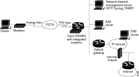
Figure 1-1 shows the topology devices used to build dialup access environments.
Figure 1-1 Network Topology Elements
Corporate users and ISPs may have identical network topologies:
•
•
•
•
•
•
•
•
•
Note
Configuration Design Parameters
Before Cisco AS5800 equipment is deployed at your site, define the following configuration design parameters:
•
•
•
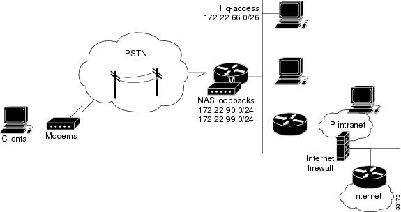
Figure 1-2 IP Subnetting Diagram
IP Subnetting Plan
The following list describes IP subnetting plan considerations. Identify network names, assigned subnets, and descriptions.
1.
–
–
2.
–
3.
–
–
4.
–
–
5.
–
Note
Device Parameters
The following list describes device parameter considerations.
1.
–
2.
–
3.
–
4.
–
5.
–
6.
–
–
7.
–
8.
–
9.
–
10.
–
–
Dial Plan
The following list describes dial plan setup considerations.
1.
–
–
2.
–
3.
–
–
Cisco IOS Software Fundamentals
Cisco IOS software provides the capability to configure a Cisco AS5800 using command-line interface (CLI) commands.
Use the following helpful reminders when configuring your Cisco IOS software:
•
•
•
•
•
Note
User Interface Command Modes
Cisco routers are configured from user interfaces, known as ports, which provide hardware connectivity. They are accessed from the console port on a router or Telnet into a router interface from another host. Typical interfaces are Serial 0 (S0), Serial 1 (S1), and Ethernet 0 (E0). Token Ring interfaces are referenced as (T0) and FDDI interfaces use (F0).
Command Modes
When using the CLI, a command interpreter, called EXEC, is employed by the operating system to translate any command and execute its operation. This command interpreter has two access modes, user and privileged, which provide security to the respective command levels. Each command mode restricts you to a subset of mode-specific commands.
User mode provides restricted access and limits router configuration or troubleshooting. At this level, miscellaneous functionality is performed, such as viewing system information, obtaining basic router status, changing terminal settings, or establishing remote device connectivity.
Privileged mode includes user mode functionality and provides unrestricted access. It is used exclusively for router configuration, debugging, setting operating system (OS) parameters, and retrieving detailed router status information.
There are many modes of configuration within privileged mode that determine the type of configuration desired, such as interface configuration (5800-1(config-if)#), line configuration (5800-1(config-line)#), and controller configuration (5800-1(config-controller)#). Each configuration command mode restricts you to a subset of mode specific commands.
In the following command sequence, command prompts are automatically modified to reflect command mode changes. A manual carriage return is implied at the end of each line item.
5800-1> enable5800-1# configure terminal5800-1(config)# interface ethernet 0/0/05800-1(config-if)# line 0/0/05800-1(config-line)# controller t1 0/0/05800-1(config-controller)# exit5800-1(config)# exit5800-1#%SYS-5-CONFIG_I: Configured from console by console5800-1#The last message is an example of a system response. Press Enter to get the 5800-1# prompt.
Table 1-1 lists common configuration modes. Configure global parameters in global configuration mode, interface parameters in interface configuration mode, and line parameters in line configuration mode.
Context-Sensitive Help
Context-sensitive help is available at any command prompt. Enter a question mark (?) for a list of complete command names, semantics, and command mode command syntax. Use arrow keys at command prompts to scroll through previous mode-specific commands for display.
Note
•
5800-1> ?•
5800-1> s?•
5800-1> show ?For more information about working with the user interface in the Cisco IOS software, refer to the document entitled Configuration Fundamentals Configuration Guide for your Cisco IOS software release, available from the Cisco.com website.
Note
Saving Configurations
To prevent losing the Cisco AS5800 configuration, save it to NVRAM using the following steps.
Step 1
5800-1> enablePassword: password5800-1#
Note
Step 2
5800-1# copy running-config startup-configBuilding configuration...The following message and prompt appears after a successful configuration copy.
[OK]5800-1#
Undoing a Command
To undo a command or disable a feature, enter the keyword no before the command; for example, no ip routing.
Basic Cisco AS5800 Start Up
This section describes how to start up your Cisco AS5800 and configure it using the prompt-driven setup script.
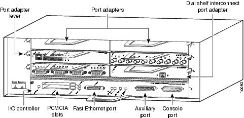
All Cisco AS5800 interfaces are configured by connecting a terminal station or PC to the Cisco 7206 router-shelf console port. This console port is located on the I/O controller front panel, as shown in Figure 1-3.
Figure 1-3 Cisco 7206 Router-Shelf Console Port
To customize your Cisco AS5800 software configuration, you should be familiar with Cisco IOS software. Review the "Cisco IOS Software Fundamentals" section to familiarize yourself with the command-line interface (CLI) commands, then continue with the "Commissioning"chapter for initial step-by-step configuration instructions.
Your Cisco AS5800 requires multiple Cisco IOS software images.
1.
2.
3.
4.
Although four Cisco IOS software images are required, only three software images (Items 1-3) require part numbers for ordering.
The dial-shelf controller image can be upgraded by copying the new image onto a Personal Computer Memory Card International Association (PCMCIA) Flash memory card on the dial-shelf controller card; however, you will soon be able to upgrade the dial-shelf controller image from the network.
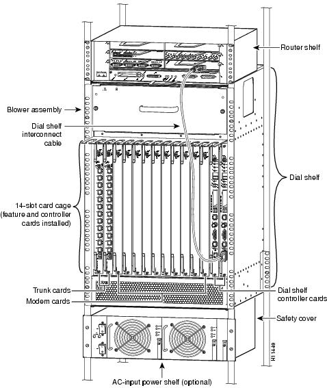
Figure 1-4 and Figure 1-5 show a rack-mounted Cisco AS5800 hardware components that require configuration or software monitoring.
Figure 1-4 Cisco AS5800 Universal Access Server—Front View
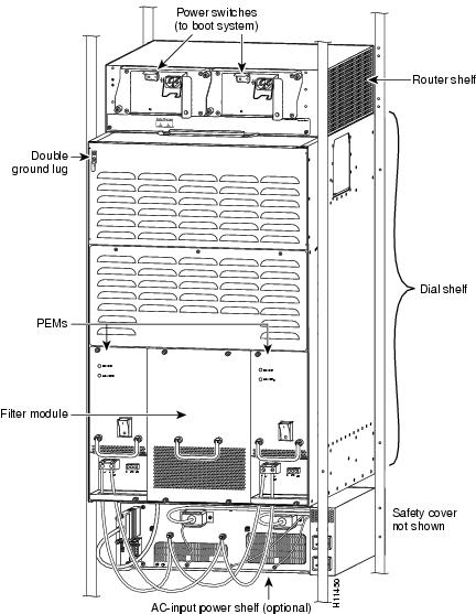
Figure 1-5 Cisco AS5800 Universal Access Server—Rear View
Cisco AS5800 First-Time Boot
When you power ON your Cisco AS5800, it goes through the following boot sequence:
1.
2.
3.
4.
5.
Cisco AS5800 Boot Process
The system boot process consists of two-stages. When the system is first powered on, the trunk cards and modem cards must receive a small image from the dial-shelf controller card, which is then launched by the ROM monitor. This allows the feature cards the ability to "talk" to the dial-shelf controller card and download the bootloader program. Communication is then made on the backplane, that allows each feature cards to talk with the router shelf the Cisco IOS software image. All cards download the bootloader image simultaneously, which then allows them to "talk" across the proprietary Fast Ethernet connection and request the image needed for each card. A hello message is exchanged between the router shelf and the dial shelf.
Because of this two-step boot process, when you first power ON your system, you might not see the feature card LEDs light immediately.
Dial-Shelf Booting
The dial shelf boots up independently from the router shelf. The dial-shelf controller card (DSC) is the first component to boot up. It is set for autobooting from internal Flash memory. If, however, a PCMCIA Flash memory card is present, the DSC tries to first boot from the card, beginning with slot 0.
Using the Setup Script
The setup script is designed to provide you with the minimum requirements needed to get your router running. The setup script enables your system controller to "talk" to the network. You can then configure your system using command-line interface (CLI) commands, or by downloading a predetermined site configuration file.
Before you power ON your Cisco AS5800 and begin using the setup script, verify that you have:
•
•
•
•
•
•
•
After you verify the information noted above, perform the configuration steps. Continue with the "Setup-Script Initial Configuration" section.
Running the Setup Script
You can run the setup script from the command line at any time using the setup command. The following commands help enable the setup command from the privileged EXEC mode.
Step 1
5800> enableStep 2
Password: password5800#Step 3
5800# setup
Passwords
Several passwords are used when configuring your Cisco IOS software. Passwords are used to identify user authorization and permission rights, virtual terminal configuration, and network management software initialization. Most passwords can use the same notation.
You need the following types of passwords when configuring Cisco IOS software:
•
•
Note
•
Setup-Script Initial Configuration
When the system is booted for the first time, NVRAM is blank. Because of this, the system software will automatically ask if you want to enter the setup script (system configuration dialog). After you have a configuration, run the setup script again to change it.
The first step is to power ON your Cisco AS5800. The power switch is located on the Cisco 7206 router-shelf rear panel. Be sure to power on the power entry modules (PEMs), which can be accessed from the Cisco 5814 dial-shelf rear panel. If you are using the optional AC-input power shelf, you also need to power on the AC-input power supplies.
Note
System Bootstrap, Version 12.x(19990210:195103) [12.0XE 105],Copyright (c) 19xx-20xx by cisco Systems, Inc.C7200 platform with 262144 Kbytes of main memorySelf decompressing the image : ###################################################################################################################################################################### [OK]Self decompressing the image : ############################################################################################################################################################################################################################################ [OK]Restricted Rights LegendUse, duplication, or disclosure by the Government is subject to restrictions as set forth in subparagraph (c) of the Commercial Computer Software - Restricted Rights clause at FAR sec. 52.227-19 and subparagraph (c) (1) (ii) of the Rights in Technical Data and Computer Software clause at DFARS sec. 252.227-7013.cisco Systems, Inc.170 West Tasman DriveSan Jose, California 95134-1706Cisco Internetwork Operating System Software IOS (tm) 5800 Software (C5800-P4-M),Copyright (c) 1986-2000 by cisco Systems, Inc.Compiled Fri 21-Jan-00 07:57 by Image text-base: 0x60008900, data-base: 0x6150C000cisco 7206VXR (NPE400) processor (revision B) with 253952K/40960K bytes of memory.Processor board ID 15376291 R7000 CPU at 262Mhz, Implementation 39, Rev 1.0, 256KB L2, 2048KB L3 Cache6 slot VXR midplane, Version 2.0Last reset from power-onX.25 software, Version 3.0.0.Bridging software.SuperLAT software (copyright 1990 by Meridian Technology Corp).Primary Rate ISDN software, Version 1.1.8 Ethernet/IEEE 802.3 interface(s)1 FastEthernet/IEEE 802.3 interface(s)4 Serial network interface(s)288 terminal line(s)12 Channelized T1/PRI port(s)125K bytes of non-volatile configuration memory.16384K bytes of Flash PCMCIA card at slot 0 (Sector size 128K).4096K bytes of Flash internal SIMM (Sector size 256K).Building configuration...[OK]Building configuration...SETUP: new interface Ethernet0/3/0 placed in "shutdown" stateSETUP: new interface Ethernet0/3/1 placed in "shutdown" stateSETUP: new interface Ethernet0/3/2 placed in "shutdown" stateSETUP: new interface Ethernet0/3/3 placed in "shutdown" stateSETUP: new interface Ethernet0/3/4 placed in "shutdown" stateSETUP: new interface Ethernet0/3/5 placed in "shutdown" stateSETUP: new interface Ethernet0/3/6 placed in "shutdown" stateSETUP: new interface Ethernet0/3/7 placed in "shutdown" statePress RETURN to get started!The system then asks if you would like to enter the system configuration dialog. Answer yes and configure your software using the system configuration dialog.
Note
Step 1
Continue with configuration dialog? [yes/no]: yesStep 2
Basic management setup configures only enough connectivity for management of the system, extended setup will ask you to configure each interface on the system
Router Shelf-ID [0]:Dial Shelf-ID [1]:
Note
Step 3
Would you like to enter basic management setup? [yes/no]: yesConfiguring global parameters:
Note
Step 4
Enter host name: 5800-1Step 5
Enter enable secret [<Use current secret>]: shhhhStep 6
Enter enable password [public]: guesswhoStep 7
Enter virtual terminal password: shhhh1Step 8
Configure System Management? [yes/no]: yesSystem Controller IP address: 10.10.1.1System Controller password: ciscoStep 9
Configure SNMP Network Management? [yes]:Community string [public]:Step 10
Enter interface name used to connect to the management network from the above interface
summary: Ethernet0/1/0
Step 11
Configuring interface Ethernet0/1/0:Configure IP on this interface? [no]:
Table 1-2 Current Interface Summary
FastEthernet0/0/0
unassigned
NO
unset
down
down
Ethernet0/1/0
10.10.1.12
YES
set
up
up
Ethernet0/1/1
unassigned
NO
unset
down
down
Ethernet0/1/2
unassigned
NO
unset
down
down
Ethernet0/1/3
unassigned
NO
unset
down
down
1 Any interface listed with OK? value "NO" does not have a valid configuration.
2 The IP address shown requires configuration by the user; it is not a default configuration.
Note
After you enter the interface used to connect to the management network, the system software will automatically display the command script that was just created.
The following configuration command script was created:hostname 5800-1enable secret 5 $1$g74v$J87e3eDZdh0wWIR7m4ELy/enable password shhhhline vty 0 4password alwaysupsyscon address 10.10.1.1 ciscosnmp-server community public!no ip routing!interface FastEthernet0/0/0shutdownno ip address!interface Ethernet0/1/0no shutdownno ip address!interface Ethernet0/1/1shutdownno ip address!interface Ethernet0/1/2shutdownno ip address!interface Ethernet0/1/3shutdownno ip address!endVerify that the command script just created is correct and enter yes at the prompt if you want to save the configuration. If you enter no at the prompt, you will need to repeat the steps described in Table 1-1 until the desired configuration file is achieved.
[0] Go back to the IOS command prompt without saving configuration[1] Return back to setup without saving this configuration[2] Save this configuration to NVRAM and exit.Selecting choice number [2] builds the configuration into NVRAM as follows:
Building configuration...Use the enabled mode 'configure' command to modify this configuration.5800#*Dec 23 12:48:58: %LINK-3-UPDOWN: Interface Ethernet0/1/0, changed state to upPress Return to display the privileged EXEC router prompt.
5800#You have just completed a basic Cisco AS5800 startup configuration; however, you will probably need to customize this configuration to further meet your site's requirements.
Deployment and Operation Strategy
The following steps describe and suggest a recommended deployment and operation task strategy for the Cisco AS5800 that serves as a functional task flow for this Guide.
Step 1
•
•
•
•
Step 2
•
•
•
Step 3
•
•
•
•
Step 4
•
•
Step 5
•
•
•
•
•
•
Step 6
•
•
•
Step 7
•
•
•
•
•
•
•
•
•
•
•
•
•
•
•
•
•
•
•
•
•
•