Feedback
Table Of Contents
Powering Off the Access Server
Replacing a DC Power Entry Module
Verifying and Troubleshooting the Installation
Replacing an AC-Input Power Supply
Removing and Replacing a Power Supply
Replacing a Dial-Shelf Controller Card
Verifying and Troubleshooting the Installation
Configuring the Dial-Shelf Controller Card
Verifying and Troubleshooting the Installation
Replacing a Dial-Shelf Interconnect Port Adapter
Removing the Dial-Shelf Interconnect Port Adapter
Replacing the Dial-Shelf Interconnect Port Adapter
Attaching the Dial-Shelf Interconnect Cable
Verifying and Troubleshooting the Installation
Replacing the Backplane Module
Maintenance
This chapter provides hardware replacement, system debugging, and troubleshooting procedures.
Replacement Procedures
This section provides detailed replacement procedures for the Cisco AS5800 field-replaceable units (FRUs) and covers the following areas:
•
Powering Off the Access Server
•
•
•
•
•
•
•
Note
http://www.cisco.com/univercd/cc/td/doc/product/core/7206/t
Instructions for rack-mounting the AC-input power shelf and for replacing an AC-input power supply are included in the Cisco AS5800 Access Server Hardware Installation Guide, available online at
http://www.cisco.com/univercd/cc/td/doc/product/access/acs_serv/as5800/hw_inst/.
Powering Off the Access Server
Some procedures in this section require you to power off the access server. See this section when appropriate.
Powering off the access server involves removing power from the following components:
•
•
•
Warning
Step 1
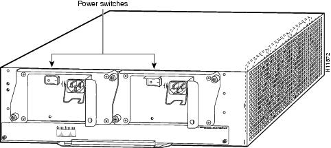
Figure 5-1 Router-Shelf Power Switches
Step 2
Figure 5-2 Dial-Shelf Power Switches on the PEMs
Step 3
Step 4
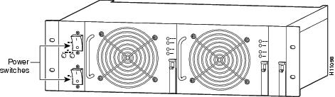
Figure 5-3 AC-Input Power Shelf
Replacing a DC Power Entry Module
This section explains how to remove and replace the power entry modules (PEMs) in the dial-shelf chassis.
Note
Tools and Parts Required
To replace a PEM you need the following items:
•
•
•
•
•
•
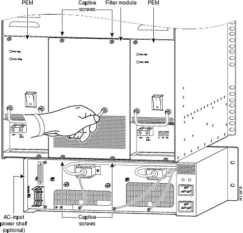
Removing a Power Entry Module
This section explains how to remove and replace the PEMs in the dial-shelf chassis.
Warning
Warning
Caution
The following procedure for hot-swapping a PEM assumes you are not using the optional AC-input power shelf, and that each PEM in your dial shelf is connected to a separate DC power source. If you are removing and replacing a PEM in an AC-configured system, you must perform the replacement during a scheduled maintenance time and power off the entire system.
Warning
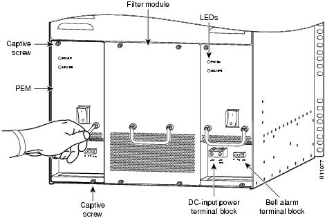
To remove a PEM, complete the following steps:
Step 1
Step 2
Step 3
Caution
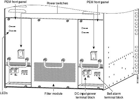
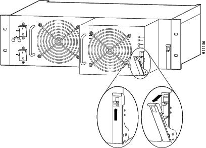
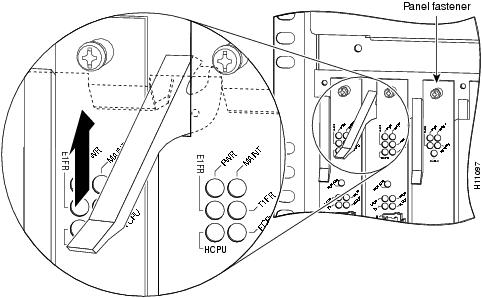
Figure 5-4 PEM Front Panel
Step 4
Step 5
Step 6
Step 7
Figure 5-5 Removing and Replacing a PEM
This completes the PEM removal process. Continue with Replacing the Power Entry Module.
Replacing the Power Entry Module
To install a new PEM, complete the following steps. (See Figure 5-5 to locate the PEMs in the dial shelf.)
Step 1
Step 2
Step 3
Step 4
This completes the procedure for replacing a PEM in the dial shelf. To connect the PEM power cables and power on the PEM, continue with section "Connecting to Your DC Power Source."
Note
Connecting to Your DC Power Source
If your site has access to a DC power source, you need to provide your own DC power cables. In the United States you need to use 6 AWG stranded or solid copper wire; elsewhere use 16 mm2 solid or 10 mm2 stranded copper wire.
To reconnect the PEM to your DC-input power source, complete the following steps:
Step 1
Step 2
Step 3
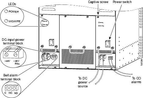
Figure 5-6 Power Entry Module (PEM) DC Terminal Block
Step 4
Step 5
Note
Step 6
Step 7
This completes the procedure for replacing a PEM and connecting to your DC power source. Continue with section "Verifying and Troubleshooting the Installation" on page 8 for installation troubleshooting tips.
Connecting to an AC Power Source
If you are using the optional AC-input power shelf, you cannot remove and replace a PEM while the system is powered on.
Caution
Verifying and Troubleshooting the Installation
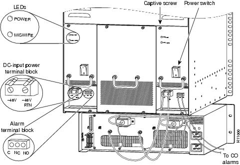
To complete the installation, verify that the power supply LEDs operate properly and that you have wired the DC-input connections correctly. Each PEM contains two LEDs on the front panel - POWER and MISWIRE. (See Figure 5-4.)
•
If neither the power nor the miswire LED is on, check the voltage at the DC-input terminal block. If the voltage reading falls between -40 and -60 VDC, replace the PEM.
•
If the miswire LED is on, the two DC conductors entering the PEM DC-input terminal block are reversed. Power OFF power at the source and reverse the connections.
This completes the procedures for installing and troubleshooting a power entry module. To verify that the PEM is properly installed, refer to the Cisco AS5800 Access Server Hardware Installation Guide, available online at
http://www.cisco.com/univercd/cc/td/doc/product/access/acs_serv/as5800/hw_inst/Replacing a Filter Module
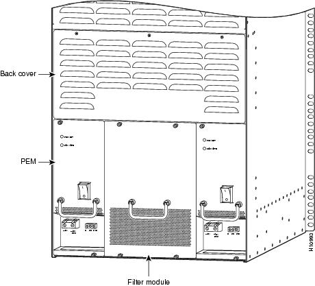
The Cisco AS5800 is equipped with a passive DC power filter, which contains a broadband electromagnetic interference (EMI) filter and circuitry for monitoring power coming into the Cisco 5814 dial shelf. The DC power filter is housed in the filter module, which resides in the dial shelf between the two power entry modules (PEMs).
Tools and Parts Required
To remove and replace the filter module you need the following parts and tools:
•
•
•
•
For additional equipment, contact a service representative for ordering information.
Removing a Filter Module
This procedure is ideally performed during a scheduled maintenance time. If not, you must first power off the dial shelf as follows:
Step 1
Figure 5-7 Dial-Shelf Power Switches on the PEMS
Step 2
Figure 5-8 AC-Input Power Shelf Power Switches
To remove the filter module from the dial shelf, complete the following steps:
Step 1
Step 2
Step 3
Step 4
Figure 5-9 Filter Module Monitor Cable Connections
Note
Caution
Step 5
Figure 5-10 Removing and Replacing the Filter Module
Step 6
Step 7
This completes the filter module removal process. Continue with Replacing the Filter Module.
Replacing the Filter Module
To replace the filter module, complete the following steps. When you are finished, use a Site Log sheet to record service maintenance.
Step 1
Step 2
Caution
Step 3
Step 4
Step 5
Step 6
This completes the procedure for removing and replacing the filter module.
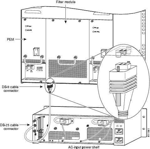
Replacing an AC-Input Power Supply
The AC-input power shelf is an optional component of the Cisco AS5800 and is used to convert AC-input power into DC-output power for the DC-powered Cisco 5814 dial shelf. The AC-input power shelf contains two AC-input power supplies.
This section explains how to remove and replace an individual power supply in the power shelf.
Tools and Parts Required
To remove and replace an individual power supply you need the following tools and parts:
•
•
•
Removing and Replacing a Power Supply
Use the following procedure if you are replacing a faulty power supply, or if you want to reduce the weight of the power shelf before you install it in a rack. If you do not want to remove power supplies prior to rack-mounting the AC-input power shelf, skip this section and continue with the "Replacing a Dial-Shelf Controller Card" section.
The AC-input power shelf is configured with two power supplies. You can remove or replace one of the power supplies without affecting system operation. When power is removed from one supply, the redundant power feature causes the second power supply to ramp up to full power and maintain uninterrupted system operation.
To remove a power supply, perform the following steps:
Caution
Step 1
Step 2
Note
Step 3
Figure 5-11 Removing and Replacing a Power Supply
Step 4
Step 5
To replace the power supply, follow these steps:
Step 1
Step 2
This completes the power supply replacement procedure.
Replacing a Dial-Shelf Controller Card
The dial-shelf controller (DSC) card serves as the interface between the dial shelf and the Cisco 7206 router shelf. This section lists tools and parts you need, and explains how to remove and replace a DSC card in the Cisco 5814 dial-shelf chassis.
Tools and Parts Required
The following parts and tools are required to remove and replace the dial-shelf controller card. If you need additional equipment, contact a service representative for ordering information.
•
•
•
•
•
•
•
Removing a Dial-Shelf Controller Card
Caution
Warning
Caution
Use the hw-module <shelf-id>/<slot-num> stop command to stop the backup DSC before you remove the backup (slave) DSC.
To remove a DSC, complete the following steps:
Note
Step 1
Caution
Step 2
Step 3
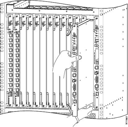
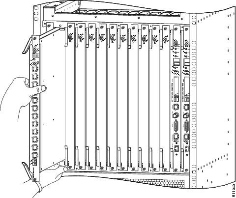
Figure 5-12 Using the Ejector Levers
Step 4
Caution
Step 5
Figure 5-13 Removing or Replacing a Dial-Shelf Controller Card
Note
Step 6
Caution
Caution
Caution
Replacing a Dial-Shelf Controller Card
Caution
Caution
Use the hw-module <shelf-id>/<slot-num> stop command to stop the backup DSC before you remove the backup (slave) DSC.
To replace a dial-shelf controller card, complete the following steps:
Note
Caution
Step 1
Caution
Step 2
Step 3
Caution
Step 4
Step 5
Caution
Step 6
Caution
This completes the steps for removing and replacing a dial-shelf controller card. For information on reconnecting the cables, see the "Connecting the Cables" section.
Note
Connecting the Cables
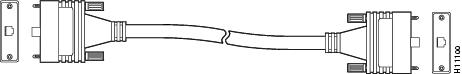
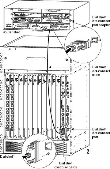
The DSC card includes a dial-shelf interconnect cable that connects the card to the dial-shelf interconnect port adapter in the Cisco 7206 router shelf. The connection between the DSC card and the dial-shelf interconnect port adapter uses a single full-duplex interconnect cable. (See Figure 5-14.)
Figure 5-14 Dial-Shelf Interconnect Cable
Attaching the Dial-Shelf Interconnect Cable
To connect the dial-shelf interconnect cable, complete the following steps:
Warning
Step 1
Step 2
Step 3
Step 4
Caution
Figure 5-15 Connecting the Dial-Shelf Interconnect Cable
Warning
For more information about the dial-shelf interconnect cable and dial-shelf interconnect port adapter, see the "Replacing a Dial-Shelf Interconnect Port Adapter" section.
Verifying and Troubleshooting the Installation
Verify that your new DSC card is properly installed and operative by observing the card LEDs as follows:
•
–
After the boot sequence completes, the alphanumeric display should read:
MSTRIf the boot sequence does not complete, contact a service representative for assistance.
–
If the problem persists with a new card installed, remove the dial-shelf controller card from the dial-shelf slot and examine the backplane for bent connector pins.
To inspect the backplane pins, first power OFF the system to avoid hazards caused by high voltages present on the backplane connectors. Next, remove cards in neighboring slots to allow an unimpeded view of the backplane connectors. Then, using a flashlight, verify that the backplane connectors are in good condition. If you discover bent pins, you need a new backplane. The backplane is an FRU. Contact your service representative to order a new backplane, and see the "Replacing the Backplane Module" section.
•
5800> enableenter password <password>5800# show diag <type {shelf | slot}>Ctrl-ZConfiguring the Dial-Shelf Controller Card
The Cisco 5814 dial shelf is designed to recognize DSC cards in specific slots within the dial-shelf chassis. Backplane slots 12 and 13 are the designated DSC card slots. This design supports redundancy features to eliminate dropped calls.
Caution
Commands for Dual-DSC-Equipped Systems
Table 5-1 shows new or modified commands have been added to support redundant-DSC-equipped systems.
Replacing a Flash Memory Card
Both the router shelf and the dial shelf contain PCMCIA slots for Flash memory cards. The router-shelf PCMCIA slots are located on the I/O controller and are oriented horizontally. The dial-shelf PCMCIA slots are located on the dial-shelf controller card and are oriented vertically. Except for the orientation of the slots, the installation procedures are the same for both shelves.
This section describes inserting and removing a Flash memory card in the dial shelf. For procedures specific to the router shelf, refer to the Cisco 7206 Installation and Configuration Guide, available online at
http://www.cisco.com/univercd/cc/td/doc/product/core/7206/The dial-shelf controller card has two PCMCIA slots for Flash memory cards. The slots are numbered left to right, slot 0 and slot 1, respectively.
Note
http://www.cisco.com/univercd/cc/td/doc/product/core/7206/To install a Flash memory card, complete the following steps:
Step 1
Step 2
Note
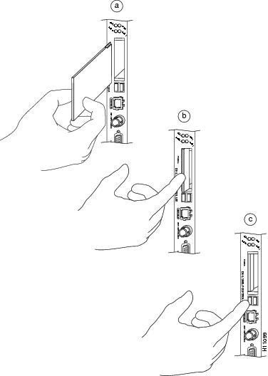
Removing a Flash Memory Card
To remove a Flash memory card from the PCMCIA slot, complete the following steps (see Figure 5-16):
Step 1
Step 2
Step 3
Figure 5-16 Inserting and Removing a PCMCIA Flash Card
This completes the dial-shelf controller card and Flash memory installation procedures.
Replacing the Blower Assembly
The Cisco AS5800 is equipped with a blower assembly, which is designed to monitor system internal operating temperatures and maintain acceptable cooling parameters.
This section explains how to remove and replace the blower assembly in the dial-shelf chassis.
Tools and Parts Required
You need the following tools and parts to remove and replace the blower assembly. If you need additional equipment, contact a service representative for ordering information.
•
•
•
•
Removing the Blower Assembly
Caution
Caution
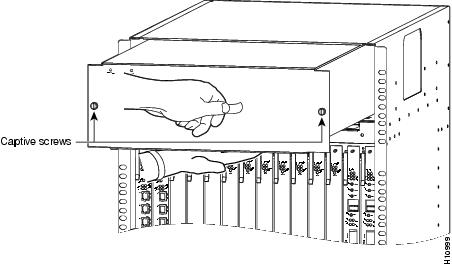
To remove the blower assembly, complete the following steps:
Step 1
Step 2
Step 3
Step 4
Step 5
Figure 5-17 Blower Assembly Removal and Replacement
This completes the blower assembly removal process. Continue with the "Replacing the Blower Assembly" section.
Replacing the Blower Assembly
To replace the blower assembly in the dial shelf, complete the following steps.
Caution
Step 1
Step 2
Step 3
Note
Step 4
Step 5
This completes the blower assembly installation procedure. Continue with the "Verifying and Troubleshooting the Installation" section to verify your installation.
Verifying and Troubleshooting the Installation
To verify that the blower assembly is properly installed and operational, complete the following steps:
Step 1
Step 2
•
Step 3
•
•
Replacing a Dial-Shelf Interconnect Port Adapter
The Cisco AS5800 is equipped with a dial-shelf interconnect port adapter that provides the connection between the Cisco 7206 router shelf and the Cisco 5814 dial shelf. The interconnect port adapter installs in the router shelf and connects to the dial shelf via a full-duplex 100-Mbps interconnect cable. The dial-shelf interconnect port adapter has no configurable ports.
The Cisco 7206 router shelf supports OIR; however, unless you have installed a second dial-shelf interconnect port adapter and established a redundant connection to the dial shelf, you must either reload the system software after removing and replacing a dial-shelf interconnect port adapter in an operating system, or you must power off the system during the replacement procedure.
You reload the system software at the router-shelf console using the reload command. For a detailed description of the reload command, refer to the configuration fundamentals command reference for your Cisco IOS release.
Note
If you power OFF and restart the system, the system software automatically reboots. For instructions on powering OFF and powering ON the access server, refer to the Cisco AS5800 Access Server Hardware Installation Guide, available online at
http://www.cisco.com/univercd/cc/td/doc/product/access/acs_serv/as5800/hw_inst/Tools and Parts Required
You need the following equipment and parts to install the dial-shelf interconnect port adapter. If you need additional equipment, contact a service representative for ordering information.
•
•
•
•
•
Note
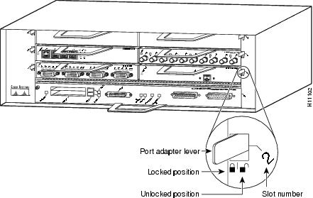
Removing the Dial-Shelf Interconnect Port Adapter
Use the following procedure to remove the dial-shelf interconnect port adapter from the router shelf:
Step 1
Step 2
Figure 5-18 Unlocked and Locked Port Adapter Lever Positions
Step 3
Step 4
Caution
Figure 5-19 Port Adapter Handling—Side View
Step 5
This completes the procedure for removing the dial-shelf interconnect port adapter from the router shelf. Continue with Replacing the Dial-Shelf Interconnect Port Adapter.
Replacing the Dial-Shelf Interconnect Port Adapter
Use the following procedure to install a new dial-shelf interconnect port adapter in the router shelf:
Step 1
Step 2
Step 3
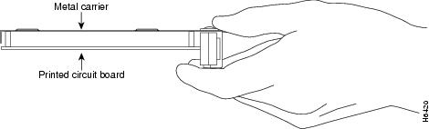
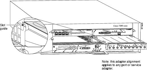
Figure 5-20 Aligning the Port Adapter Metal Carrier Between the Slot Guides
Step 4
Step 5
Note
This completes the procedure for installing a new dial-shelf interconnect port adapter in the router shelf. Continue with the "Attaching the Dial-Shelf Interconnect Cable" section.
Attaching the Dial-Shelf Interconnect Cable
The interconnect port adapter includes a single dial-shelf interconnect receptacle. For a redundant connection to the dial shelf, you need to install a second port adapter.
Caution
Connect the dial-shelf interconnect cable as follows:
Step 1
Step 2
Step 3
Figure 5-21 Connecting the Dial-Shelf Interconnect Cable
Warning
Step 4
Step 5
This completes the dial-shelf interconnect cable installation procedure. To verify the installation, continue with the "Verifying and Troubleshooting the Installation" section.
Verifying and Troubleshooting the Installation
To complete the installation, verify that the LEDs operate properly by observing the following LED states on the dial-shelf interconnect port adapter:
•
If the enabled LED is off, the interconnect port adapter may have pulled away from the midplane. Reseat the interconnect port adapter in its slot.
If the enabled LED remains off, contact a service representative for assistance.
•
If the link LED is off, check the interconnect cable connection and tighten the jackscrews.
•
This completes the dial-shelf interconnect port adapter installation. For hardware troubleshooting procedures, refer to the Cisco 7206 Installation and Configuration Guide, available online at
http://www.cisco.com/univercd/cc/td/doc/product/core/7206/Replacing the Backplane Module
The Cisco AS5800 includes a passive backplane in the Cisco 5814 dial shelf that can be ordered as a spare. This section explains how to remove and replace the backplane in the Cisco 5814 dial-shelf chassis.
In most cases, the Cisco 5814 dial-shelf chassis will be fully installed to include the dial-shelf controller card and feature cards. As part of the backplane removal, unseat all cards from the dial-shelf backplane.
Warning
Warning
In this section you will be instructed to perform the following actions:
1.
2.
3.
4.
5.
6.
Note
Tools and Parts Required
The following parts and tools are required to remove and replace the backplane module. If you need additional equipment, contact a service representative for ordering information.
•
•
•
•
•
•
•
Removing the Backplane
The backplane cannot be removed while the system is powered on. This procedure is ideally performed during a scheduled maintenance time. If not, you must first power OFF the system.
Warning
To remove the backplane:
Step 1
Figure 5-22 Router-Shelf Power Switches
Step 2
Figure 5-23 Dial-Shelf Power Switches on the PEMS
Step 3
Figure 5-24 AC-Input Power Shelf
Step 4
To continue, you must next disconnect power cables and alarm cables to the dial-shelf PEMs.
Step 1
Figure 5-25 PEM Cable and Alarm Terminal Blocks
The following steps refer to the optional AC-input power shelf. If you are using a DC power source, you can skip Step 2 and Step 3.
Step 2
Figure 5-26 Filter Module Monitor Cable DB-9 Connector
.
Step 3
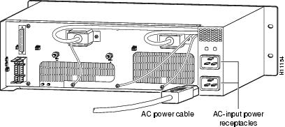
Figure 5-27 AC-Input Power Shelf Cable Connections
.
After you disconnect the cables, you must disconnect the dial-shelf controller cards and feature cards from the backplane connectors. You do not need to remove the cards completely from the dial-shelf chassis; however, you must disconnect incoming CE1/CT1 trunk line cables.
To disconnect the feature cards and dial-shelf controller cards from the backplane, follow these steps:
Step 1
Step 2
Warning
Step 3
Step 4
Figure 5-28 Ejector Lever Enlarged
Step 5
Figure 5-29 Removing Feature Cards and Dial-Shelf Controller Cards
Return to the rear of the dial shelf and continue by removing the PEMs, the filter module, and the back cover. You also need to remove the horizontal bar that attaches the bottom of the back cover and the tops of the PEMs and filter module to the chassis.
Step 1
Step 2
Figure 5-30 PEM Removal
Step 3
Step 4
Figure 5-31 Filter Module Removal
Step 5
Figure 5-32 Dial-Shelf Chassis Back Cover
.
Step 6
To complete the backplane removal procedure, complete the following steps:
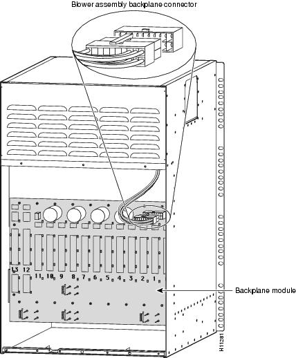
Step 1
Figure 5-33 Blower Assembly Backplane Connector
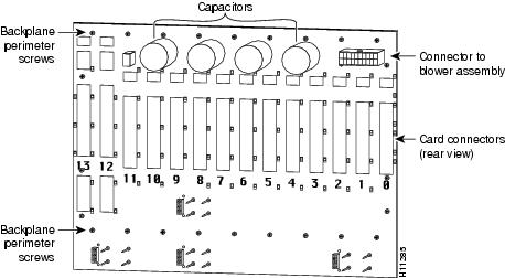
Step 2
Figure 5-34 Backplane Module—Rear View
Step 3
Replacing the Backplane
To replace the backplane complete the following steps and reverse the procedures used to remove cables and components. When you finish, use a Site Log sheet to record service maintenance.
Step 1
Step 2
Step 3
Step 4
Step 5
Step 6
Step 7
Step 8
Step 9
Step 10
Step 11
Step 12
This completes the backplane removal and replacement procedure. The backplane is a passive design. Specific verification and troubleshooting instructions are considered unnecessary.
Troubleshooting
This section describes possible causes for specific symptom related to Cisco AS5800 hardware components and software configurations.
For system startup and subsystem troubleshooting, refer to the chapter on troubleshooting in the Cisco AS5800 Access Server Hardware Installation Guide, available online at
http://www.cisco.com/univercd/cc/td/doc/product/access/acs_serv/as5800/hw_inst/Common Misconfigurations
•
•
•
•
•
•
•
AS5800 Router Shelf
Symptom
•
Possible Cause
•
•
•
AS5800 Dial Shelf
Symptom
•
•
Possible Cause
•
•
•
Feature Cards
Symptom
•
Possible Cause
•
•
•
•
Controller T1
Symptom
•
Possible Cause
•
•
•
General Configuration
Symptom
•
Possible Cause
•
•
•
Symptom
•
Possible Cause
•
•
•
Symptom
•
Possible Cause
•
•
•
•
Symptom
•
Possible Cause
•
•
Async Calls
Symptom
•
Possible Cause
•
•
•
•
•
Symptom
•
Possible Cause
•
•
•
Symptom
•
Possible Cause
•
•
•
•
Interactive Async User
Symptom
•
Possible Cause
•
•
Interactive Users
Symptom
•
Possible Cause
•
•
Symptom
•
Possible Cause
•
•
Symptom
•
Possible Cause
•
–
•
Dedicated-PPP Users
Symptom
•
Possible Cause
•
•
•
•
Symptom
•
Possible Cause
•
•
•
PPP Users
Symptom
•
Possible Cause
•
•
•
•
Sync Calls
Symptom
•
Possible Cause
•
•
•
•
MMPPP
Symptom
•
Possible Cause
•
•
Symptom
•
Possible Cause
•
•
RADIUS
Symptom
•
Possible Cause
•
•
•
•
Symptom
•
Possible Cause
•
•
•
Symptom
•
Possible Cause
•
SGBP Troubleshooting
Debug Commands
•
•