- Configuring GLBP
- HSRP Version 2
- FHRP—HSRP BFD Peering
- FHRP - HSRP Group Shutdown
- FHRP - HSRP MIB
- HSRP MD5 Authentication
- HSRP Support for ICMP Redirects
- HSRP Support for MPLS VPNs
- FHRP - HSRP Multiple Group Optimization
- Configuring IRDP
- Configuring VRRP
- VRRPv3 Protocol Support
- VRRPv3: Object Tracking Integration
- Finding Feature Information
- Restrictions for VRRP
- Information About VRRP
- How to Configure VRRP
- Customizing VRRP
- Enabling VRRP
- Disabling a VRRP Group on an Interface
- Configuring VRRP Object Tracking
- Configuring VRRP MD5 Authentication Using a Key String
- Configuring VRRP MD5 Authentication Using a Key Chain
- Verifying the VRRP MD5 Authentication Configuration
- Configuring VRRP Text Authentication
- Enabling the Router to Send SNMP VRRP Notifications
- Configuration Examples for VRRP
- Example: Configuring VRRP
- Example: VRRP Object Tracking
- Example: VRRP Object Tracking Verification
- Example: VRRP MD5 Authentication Configuration Using a Key String
- Example: VRRP MD5 Authentication Configuration Using a Key Chain
- Example: VRRP Text Authentication
- Example: Disabling a VRRP Group on an Interface
- Example: VRRP MIB Trap
- Additional References for Configuring VRRP
- Feature Information for VRRP
- Glossary
Configuring VRRP
The Virtual Router Redundancy Protocol (VRRP) is an election protocol that dynamically assigns responsibility for one or more virtual routers to the VRRP routers on a LAN, allowing several routers on a multiaccess link to utilize the same virtual IP address. A VRRP router is configured to run the VRRP protocol in conjunction with one or more other routers attached to a LAN. In a VRRP configuration, one router is elected as the virtual router master, with the other routers acting as backups in case the virtual router master fails.
This module explains the concepts related to VRRP and describes how to configure VRRP in a network.
- Finding Feature Information
- Restrictions for VRRP
- Information About VRRP
- How to Configure VRRP
- Configuration Examples for VRRP
- Additional References for Configuring VRRP
- Feature Information for VRRP
- Glossary
Finding Feature Information
Your software release may not support all the features documented in this module. For the latest caveats and feature information, see Bug Search Tool and the release notes for your platform and software release. To find information about the features documented in this module, and to see a list of the releases in which each feature is supported, see the feature information table.
Use Cisco Feature Navigator to find information about platform support and Cisco software image support. To access Cisco Feature Navigator, go to www.cisco.com/go/cfn. An account on Cisco.com is not required.
Restrictions for VRRP
-
VRRP is designed for use over multiaccess, multicast, or broadcast capable Ethernet LANs. VRRP is not intended as a replacement for existing dynamic protocols.
-
VRRP is supported on Ethernet, Fast Ethernet, Bridge Group Virtual Interface (BVI), and Gigabit Ethernet interfaces, and on Multiprotocol Label Switching (MPLS) Virtual Private Networks (VPNs), VRF-aware MPLS VPNs, and VLANs.
-
Because of the forwarding delay that is associated with the initialization of a BVI interface, you must configure the VRRP advertise timer to a value equal to or greater than the forwarding delay on the BVI interface. This setting prevents a VRRP router on a recently initialized BVI interface from unconditionally taking over the master role. Use the bridge forward-time command to set the forwarding delay on the BVI interface. Use the vrrp timers advertise command to set the VRRP advertisement timer.
Information About VRRP
- VRRP Operation
- VRRP Benefits
- Multiple Virtual Router Support
- VRRP Router Priority and Preemption
- VRRP Advertisements
- VRRP Object Tracking
- How Object Tracking Affects the Priority of a VRRP Router
- VRRP Authentication
- In Service Software Upgrade--VRRP
- VRRP Support for Stateful Switchover
VRRP Operation
There are several ways a LAN client can determine which router should be the first hop to a particular remote destination. The client can use a dynamic process or static configuration. Examples of dynamic router discovery are as follows:
Proxy ARP—The client uses Address Resolution Protocol (ARP) to get the destination it wants to reach, and a router will respond to the ARP request with its own MAC address.
Routing protocol—The client listens to dynamic routing protocol updates (for example, from Routing Information Protocol [RIP]) and forms its own routing table.
ICMP Router Discovery Protocol (IRDP) client—The client runs an Internet Control Message Protocol (ICMP) router discovery client.
The drawback to dynamic discovery protocols is that they incur some configuration and processing overhead on the LAN client. Also, in the event of a router failure, the process of switching to another router can be slow.
An alternative to dynamic discovery protocols is to statically configure a default router on the client. This approach simplifies client configuration and processing, but creates a single point of failure. If the default gateway fails, the LAN client is limited to communicating only on the local IP network segment and is cut off from the rest of the network.
VRRP can solve the static configuration problem. VRRP enables a group of routers to form a single virtual router. The LAN clients can then be configured with the virtual router as their default gateway. The virtual router, representing a group of routers, is also known as a VRRP group.
VRRP is supported on Ethernet, Fast Ethernet, BVI, and Gigabit Ethernet interfaces, and on MPLS VPNs, VRF-aware MPLS VPNs, and VLANs.
The figure below shows a LAN topology in which VRRP is configured. In this example, Routers A, B, and C are VRRP routers (routers running VRRP) that comprise a virtual router. The IP address of the virtual router is the same as that configured for the Ethernet interface of Router A (10.0.0.1).
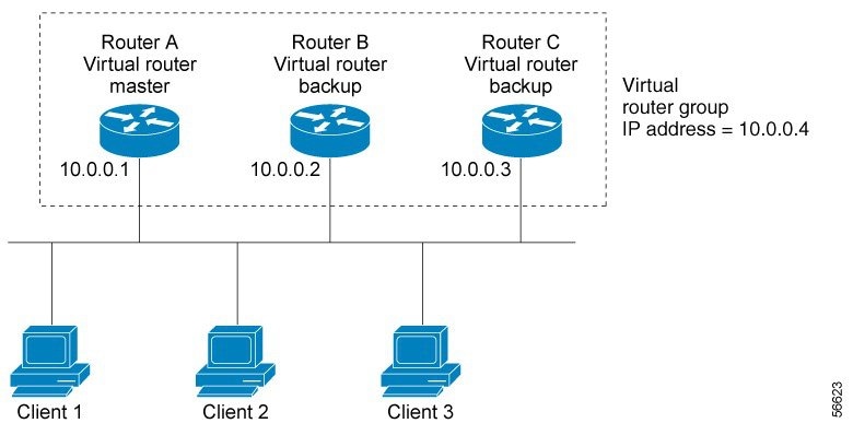
Because the virtual router uses the IP address of the physical Ethernet interface of Router A, Router A assumes the role of the virtual router master and is also known as the IP address owner. As the virtual router master, Router A controls the IP address of the virtual router and is responsible for forwarding packets sent to this IP address. Clients 1 through 3 are configured with the default gateway IP address of 10.0.0.1.
Routers B and C function as virtual router backups. If the virtual router master fails, the router configured with the higher priority will become the virtual router master and provide uninterrupted service for the LAN hosts. When Router A recovers, it becomes the virtual router master again. For more detail on the roles that VRRP routers play and what happens if the virtual router master fails, see the VRRP Router Priority and Preemption section.
The figure below shows a LAN topology in which VRRP is configured so that Routers A and B share the traffic to and from clients 1 through 4 and that Routers A and B act as virtual router backups to each other if either router fails.

In this topology, two virtual routers are configured. (For more information, see the Multiple Virtual Router Support section.) For virtual router 1, Router A is the owner of IP address 10.0.0.1 and virtual router master, and Router B is the virtual router backup to Router A. Clients 1 and 2 are configured with the default gateway IP address of 10.0.0.1.
For virtual router 2, Router B is the owner of IP address 10.0.0.2 and virtual router master, and Router A is the virtual router backup to Router B. Clients 3 and 4 are configured with the default gateway IP address of 10.0.0.2.
VRRP Benefits
Redundancy
VRRP enables you to configure multiple routers as the default gateway router, which reduces the possibility of a single point of failure in a network.
Load Sharing
You can configure VRRP in such a way that traffic to and from LAN clients can be shared by multiple routers, thereby sharing the traffic load more equitably among available routers.
Multiple Virtual Routers
Multiple IP Addresses
The virtual router can manage multiple IP addresses, including secondary IP addresses. Therefore, if you have multiple subnets configured on an Ethernet interface, you can configure VRRP on each subnet.
Preemption
The redundancy scheme of VRRP enables you to preempt a virtual router backup that has taken over for a failing virtual router master with a higher priority virtual router backup that has become available.
Authentication
VRRP message digest 5 (MD5) algorithm authentication protects against VRRP-spoofing software and uses the industry-standard MD5 algorithm for improved reliability and security.
Advertisement Protocol
VRRP uses a dedicated Internet Assigned Numbers Authority (IANA) standard multicast address (224.0.0.18) for VRRP advertisements. This addressing scheme minimizes the number of routers that must service the multicasts and allows test equipment to accurately identify VRRP packets on a segment. The IANA assigned VRRP the IP protocol number 112.
VRRP Object Tracking
VRRP object tracking provides a way to ensure the best VRRP router is the virtual router master for the group by altering VRRP priorities to the status of tracked objects such as the interface or IP route states.
Multiple Virtual Router Support
-
Router processing capability
-
Router memory capability
-
Router interface support of multiple MAC addresses
In a topology where multiple virtual routers are configured on a router interface, the interface can act as a master for one virtual router and as a backup for one or more virtual routers.
VRRP Router Priority and Preemption
An important aspect of the VRRP redundancy scheme is VRRP router priority. Priority determines the role that each VRRP router plays and what happens if the virtual router master fails.
If a VRRP router owns the IP address of the virtual router and the IP address of the physical interface, this router will function as a virtual router master.
Priority also determines if a VRRP router functions as a virtual router backup and the order of ascendancy to becoming a virtual router master if the virtual router master fails. You can configure the priority of each virtual router backup with a value of 1 through 254 using the vrrp priority command.
For example, if Router A, the virtual router master in a LAN topology, fails, an election process takes place to determine if virtual router backups B or C should take over. If Routers B and C are configured with the priorities of 101 and 100, respectively, Router B is elected to become virtual router master because it has the higher priority. If Routers B and C are both configured with the priority of 100, the virtual router backup with the higher IP address is elected to become the virtual router master.
By default, a preemptive scheme is enabled whereby a higher priority virtual router backup that becomes available takes over for the virtual router backup that was elected to become virtual router master. You can disable this preemptive scheme using the no vrrp preempt command. If preemption is disabled, the virtual router backup that is elected to become virtual router master remains the master until the original virtual router master recovers and becomes master again.
VRRP Advertisements
The virtual router master sends VRRP advertisements to other VRRP routers in the same group. The advertisements communicate the priority and state of the virtual router master. The VRRP advertisements are encapsulated in IP packets and sent to the IP Version 4 multicast address assigned to the VRRP group. The advertisements are sent every second by default; the interval is configurable.
Although the VRRP protocol as per RFC 3768 does not support millisecond timers, Cisco routers allow you to configure millisecond timers. You need to manually configure the millisecond timer values on both the primary and the backup routers. The master advertisement value displayed in the show vrrp command output on the backup routers is always 1 second because the packets on the backup routers do not accept millisecond values.
You must use millisecond timers where absolutely necessary and with careful consideration and testing. Millisecond values work only under favorable circumstances, and you must be aware that the use of the millisecond timer values restricts VRRP operation to Cisco devices only.
VRRP Object Tracking
Object tracking is an independent process that manages creating, monitoring, and removing tracked objects such as the state of the line protocol of an interface. Clients such as the Hot Standby Router Protocol (HSRP), Gateway Load Balancing Protocol (GLBP), and VRRP register their interest with specific tracked objects and act when the state of an object changes.
Each tracked object is identified by a unique number that is specified on the tracking CLI. Client processes such as VRRP use this number to track a specific object.
The tracking process periodically polls the tracked objects and notes any change of value. The changes in the tracked object are communicated to interested client processes, either immediately or after a specified delay. The object values are reported as either up or down.
VRRP object tracking gives VRRP access to all the objects available through the tracking process. The tracking process allows you to track individual objects such as a the state of an interface line protocol, state of an IP route, or the reachability of a route.
VRRP provides an interface to the tracking process. Each VRRP group can track multiple objects that may affect the priority of the VRRP device. You specify the object number to be tracked and VRRP is notified of any change to the object. VRRP increments (or decrements) the priority of the virtual device based on the state of the object being tracked.
How Object Tracking Affects the Priority of a VRRP Router
The priority of a device can change dynamically if it has been configured for object tracking and the object that is being tracked goes down. The tracking process periodically polls the tracked objects and notes any change of value. The changes in the tracked object are communicated to VRRP, either immediately or after a specified delay. The object values are reported as either up or down. Examples of objects that can be tracked are the line protocol state of an interface or the reachability of an IP route. If the specified object goes down, the VRRP priority is reduced. The VRRP router with the higher priority can now become the virtual router master if it has the vrrp preempt command configured. See the VRRP Object Tracking section for more information on object tracking.
VRRP Authentication
VRRP ignores unauthenticated VRRP protocol messages. The default authentication type is text authentication.
You can configure VRRP text authentication, authentication using a simple MD5 key string, or MD5 key chains for authentication.
MD5 authentication provides greater security than the alternative plain text authentication scheme. MD5 authentication allows each VRRP group member to use a secret key to generate a keyed MD5 hash of the packet that is part of the outgoing packet. A keyed hash of an incoming packet is generated and if the generated hash does not match the hash within the incoming packet, the packet is ignored.
The key for the MD5 hash can either be given directly in the configuration using a key string or supplied indirectly through a key chain.
A router will ignore incoming VRRP packets from routers that do not have the same authentication configuration for a VRRP group. VRRP has three authentication schemes:
No authentication
Plain text authentication
MD5 authentication
VRRP packets will be rejected in any of the following cases:
The authentication schemes differ on the router and in the incoming packet.
MD5 digests differ on the router and in the incoming packet.
Text authentication strings differ on the router and in the incoming packet.
In Service Software Upgrade--VRRP
VRRP supports In Service Software Upgrade (ISSU). In Service Software Upgrade (ISSU) allows a high-availability (HA) system to run in stateful switchover (SSO) mode even when different versions of Cisco IOS software are running on the active and standby Route Processors (RPs) or line cards.
ISSU provides the ability to upgrade or downgrade from one supported Cisco IOSrelease to another while continuing to forward packets and maintain sessions, thereby reducing planned outage time. The ability to upgrade or downgrade is achieved by running different software versions on the active RP and standby RP for a short period of time to maintain state information between RPs. This feature allows the system to switch over to a secondary RP running upgraded (or downgraded) software and continue forwarding packets without session loss and with minimal or no packet loss. This feature is enabled by default.
For detailed information about ISSU, see theCisco IOS In Service Software Upgrade Process document in the Cisco IOS High Availability Configuration Guide.
VRRP Support for Stateful Switchover
With the introduction of the VRRP Support for Stateful Switchover feature, VRRP is SSO aware. VRRP can detect when a router is failing over to the secondary RP and continue in its current group state.
SSO functions in networking devices (usually edge devices) that support dual Route Processors (RPs). SSO provides RP redundancy by establishing one of the RPs as the active processor and the other RP as the standby processor. SSO also synchronizes critical state information between the RPs so that network state information is dynamically maintained between RPs.
Prior to being SSO aware, if VRRP was deployed on a router with redundant RPs, a switchover of roles between the active RP and the standby RP would result in the router relinquishing its activity as a VRRP group member and then rejoining the group as if it had been reloaded. The SSO--VRRP feature enables VRRP to continue its activities as a group member during a switchover. VRRP state information between redundant RPs is maintained so that the standby RP can continue the router’s activities within the VRRP during and after a switchover.
This feature is enabled by default. To disable this feature, use the no vrrp sso command in global configuration mode.
For more information, see the Stateful Switchover document.
How to Configure VRRP
- Customizing VRRP
- Enabling VRRP
- Disabling a VRRP Group on an Interface
- Configuring VRRP Object Tracking
- Configuring VRRP MD5 Authentication Using a Key String
- Configuring VRRP MD5 Authentication Using a Key Chain
- Verifying the VRRP MD5 Authentication Configuration
- Configuring VRRP Text Authentication
- Enabling the Router to Send SNMP VRRP Notifications
Customizing VRRP
Customizing the behavior of VRRP is optional. Be aware that as soon as you enable a VRRP group, that group is operating. It is possible that if you first enable a VRRP group before customizing VRRP, the router could take over control of the group and become the virtual router master before you have finished customizing the feature. Therefore, if you plan to customize VRRP, it is a good idea to do so before enabling VRRP.
1.
enable
2.
configure
terminal
3.
interface
type
number
4.
ip
address
ip-address
mask
5.
vrrp
group
description
text
6.
vrrp
group
priority
level
7.
vrrp
group
preempt [delay
minimum
seconds]
8.
vrrp
group
timers
learn
9.
exit
10.
no
vrrp
sso
DETAILED STEPS
Enabling VRRP
1.
enable
2.
configure
terminal
3.
interface
type
number
4.
ip
address
ip-address
mask
5.
vrrp
group
ip
ip-address [secondary]
6.
end
7.
show
vrrp [brief] |
group]
8.
show
vrrp
interface
type
number [brief]
DETAILED STEPS
Disabling a VRRP Group on an Interface
Disabling a VRRP group on an interface allows the protocol to be disabled, but the configuration to be retained. This ability was added with the introduction of the VRRP MIB, RFC 2787, Definitions of Managed Objects for the Virtual Router Redundancy Protocol .
You can use a Simple Network Management Protocol (SNMP) management tool to enable or disable VRRP on an interface. Because of the SNMP management capability, the vrrp shutdown command was introduced to represent a method via the command line interface (CLI) for VRRP to show the state that had been configured using SNMP.
When the show running-config command is entered, you can see immediately if the VRRP group has been configured and set to enabled or disabled. This is the same functionality that is enabled within the MIB.
The no form of the command enables the same operation that is performed within the MIB. If the vrrp shutdown command is specified using the SNMP interface, then entering the no vrrp shutdown command reenables the VRRP group.
1.
enable
2.
configure
terminal
3.
interface
type
number
4.
ip
address
ip-address
mask
5.
vrrp
group
shutdown
DETAILED STEPS
| Command or Action | Purpose | |||
|---|---|---|---|---|
| Step 1 |
enable
Example: Router> enable |
Enables privileged EXEC mode. | ||
| Step 2 |
configure
terminal
Example: Router# configure terminal |
Enters global configuration mode. | ||
| Step 3 |
interface
type
number
Example: Router(config)# interface GigabitEthernet0/0/0 |
Enters interface configuration mode. | ||
| Step 4 |
ip
address
ip-address
mask
Example: Router(config-if)# ip address 172.16.6.5 255.255.255.0 | Configures an IP address for an interface. | ||
| Step 5 |
vrrp
group
shutdown
Example: Router(config-if)# vrrp 10 shutdown |
Disables the VRRP group on an interface.
|
Configuring VRRP Object Tracking
 Note | If a VRRP group is the IP address owner, its priority is fixed at 255 and cannot be reduced through object tracking. |
1.
enable
2.
configure
terminal
3.
track
object-number
interface
type
number {line-protocol |
ip
routing}
4.
interface
type
number
5.
vrrp
group
ip
ip-address
6.
vrrp
group
priority
level
7.
vrrp
group
track
object-number [decrement
priority]
8.
end
9.
show
track [object-number]
DETAILED STEPS
| Command or Action | Purpose | |
|---|---|---|
| Step 1 |
enable
Example: Router> enable |
Enables privileged EXEC mode. |
| Step 2 |
configure
terminal
Example: Router# configure terminal |
Enters global configuration mode. |
| Step 3 |
track
object-number
interface
type
number {line-protocol |
ip
routing}
Example: Router(config)# track 2 interface serial 6 line-protocol |
Configures an interface to be tracked where changes in the state of the interface affect the priority of a VRRP group.
|
| Step 4 |
interface
type
number
Example: Router(config)# interface Ethernet 2 |
Enters interface configuration mode. |
| Step 5 |
vrrp
group
ip
ip-address
Example: Router(config-if)# vrrp 1 ip 10.0.1.20 |
Enables VRRP on an interface and identifies the IP address of the virtual router. |
| Step 6 |
vrrp
group
priority
level
Example: Router(config-if)# vrrp 1 priority 120 |
Sets the priority level of the router within a VRRP group. |
| Step 7 |
vrrp
group
track
object-number [decrement
priority]
Example: Router(config-if)# vrrp 1 track 2 decrement 15 |
Configures VRRP to track an object. |
| Step 8 |
end
Example: Router(config-if)# end |
Returns to privileged EXEC mode. |
| Step 9 |
show
track [object-number]
Example: Router# show track 1 |
Displays tracking information. |
Configuring VRRP MD5 Authentication Using a Key String
Note | Interoperability with vendors that may have implemented the RFC 2338 method is not enabled. Text authentication cannot be combined with MD5 authentication for a VRRP group at any one time. When MD5 authentication is configured, the text authentication field in VRRP hello messages is set to all zeroes on transmit and ignored on receipt, provided the receiving router also has MD5 authentication enabled. |
1.
enable
2.
configure
terminal
3.
interface
type
number
4.
ip
address
ip-address
mask
[secondary]
5.
vrrp
group
priority
priority
6.
vrrp
group
authentication
md5
key-string
[0 | 7] key-string [timeout seconds]
7.
vrrp
group
ip
[ip-address[secondary]]
8. Repeat Steps 1 through 7 on each router that will communicate.
9.
end
DETAILED STEPS
| Command or Action | Purpose | |||
|---|---|---|---|---|
| Step 1 |
enable
Example: Router> enable |
Enables privileged EXEC mode.
| ||
| Step 2 |
configure
terminal
Example: Router# configure terminal |
Enters global configuration mode. | ||
| Step 3 |
interface
type
number
Example: Router(config)# interface Ethernet0/1 |
Configures an interface type and enters interface configuration mode. | ||
| Step 4 |
ip
address
ip-address
mask
[secondary] Example: Router(config-if)# ip address 10.0.0.1 255.255.255.0 |
Specifies a primary or secondary IP address for an interface. | ||
| Step 5 |
vrrp
group
priority
priority
Example: Router(config-if)# vrrp 1 priority 110 |
Configures VRRP priority. | ||
| Step 6 |
vrrp
group
authentication
md5
key-string
[0 | 7] key-string [timeout seconds] Example: Router(config-if)# vrrp 1 authentication md5 key-string d00b4r987654321a timeout 30 |
Configures an authentication string for VRRP MD5 authentication.
| ||
| Step 7 |
vrrp
group
ip
[ip-address[secondary]] Example: Router(config-if)# vrrp 1 ip 10.0.0.3 |
Enables VRRP on an interface and identifies the IP address of the virtual router. | ||
| Step 8 | Repeat Steps 1 through 7 on each router that will communicate. |
-- | ||
| Step 9 |
end
Example: Router(config-if)# end |
Returns to privileged EXEC mode. |
Configuring VRRP MD5 Authentication Using a Key Chain
Perform this task to configure VRRP MD5 authentication using a key chain. Key chains allow a different key string to be used at different times according to the key chain configuration. VRRP will query the appropriate key chain to obtain the current live key and key ID for the specified key chain.
Note | Interoperability with vendors that may have implemented the RFC 2338 method is not enabled. Text authentication cannot be combined with MD5 authentication for a VRRP group at any one time. When MD5 authentication is configured, the text authentication field in VRRP hello messages is set to all zeroes on transmit and ignored on receipt, provided the receiving router also has MD5 authentication enabled. |
1.
enable
2.
configure
terminal
3.
key
chain
name-of-chain
4.
key
key-id
5.
key-string
string
6.
exit
7.
interface
type
number
8.
ip
address
ip-address
mask
[secondary]
9.
vrrp
group
priority
priority
10.
vrrp
group
authentication
md5
key-chain
key-chain
11.
vrrp
group
ip
[ip-address[secondary]]
12. Repeat Steps 1 through 11 on each router that will communicate.
13.
end
DETAILED STEPS
| Command or Action | Purpose | |||
|---|---|---|---|---|
| Step 1 |
enable
Example: Router> enable |
Enables privileged EXEC mode.
| ||
| Step 2 |
configure
terminal
Example: Router# configure terminal |
Enters global configuration mode. | ||
| Step 3 |
key
chain
name-of-chain
Example: Router(config)# key chain vrrp1 |
Enables authentication for routing protocols and identifies a group of authentication keys. | ||
| Step 4 |
key
key-id
Example: Router(config-keychain)# key 100 |
Identifies an authentication key on a key chain.
| ||
| Step 5 |
key-string
string
Example: Router(config-keychain-key)# key-string mno172 |
Specifies the authentication string for a key.
| ||
| Step 6 |
exit
Example: Router(config-keychain-key)# exit |
Returns to global configuration mode. | ||
| Step 7 |
interface
type
number
Example: Router(config)# interface Ethernet0/1 |
Configures an interface type and enters interface configuration mode. | ||
| Step 8 |
ip
address
ip-address
mask
[secondary] Example: Router(config-if)# ip address 10.21.8.32 255.255.255.0 |
Specifies a primary or secondary IP address for an interface. | ||
| Step 9 |
vrrp
group
priority
priority
Example: Router(config-if)# vrrp 1 priority 110 |
Configures VRRP priority. | ||
| Step 10 |
vrrp
group
authentication
md5
key-chain
key-chain
Example: Router(config-if)# vrrp 1 authentication md5 key-chain vrrp1 |
Configures an authentication MD5 key chain for VRRP MD5 authentication.
| ||
| Step 11 |
vrrp
group
ip
[ip-address[secondary]] Example: Router(config-if)# vrrp 1 ip 10.21.8.12 |
Enables VRRP on an interface and identifies the IP address of the virtual router.
| ||
| Step 12 | Repeat Steps 1 through 11 on each router that will communicate. |
-- | ||
| Step 13 |
end
Example: Router(config-if)# end |
Returns to privileged EXEC mode. |
Verifying the VRRP MD5 Authentication Configuration
1.
show
vrrp
2.
debug
vrrp
authentication
DETAILED STEPS
| Step 1 |
show
vrrp
Use this command to verify that the authentication is configured correctly: Example: Router# show vrrp Ethernet0/1 - Group 1 State is Master Virtual IP address is 10.21.0.10 Virtual MAC address is 0000.5e00.0101 Advertisement interval is 1.000 sec Preemption is enabled min delay is 0.000 sec Priority is 100 Authentication MD5, key-string, timeout 30 secs Master Router is 10.21.0.1 (local), priority is 100 Master Advertisement interval is 1.000 sec Master Down interval is 3.609 sec This output shows that MD5 authentication is configured and the f00d4s key string is used. The timeout value is set at 30 seconds. |
| Step 2 |
debug
vrrp
authentication
Use this command to verify that both routers have authentication configured, that the MD5 key ID is the same on each router, and that the MD5 key strings are the same on each router: Example: Router1#: debug vrrp authentication VRRP: Sent: 21016401FE050000AC1801FE0000000000000000 VRRP: HshC: B861CBF1B9026130DD34AED849BEC8A1 VRRP: Rcvd: 21016401FE050000AC1801FE0000000000000000 VRRP: HshC: B861CBF1B9026130DD34AED849BEC8A1 VRRP: HshR: C5E193C6D84533FDC750F85FCFB051E1 VRRP: Grp 1 Adv from 172.24.1.2 has failed MD5 auth Router2#: debug vrrp authentication VRRP: Sent: 21016401FE050000AC1801FE0000000000000000 VRRP: HshC: C5E193C6D84533FDC750F85FCFB051E1 VRRP: Rcvd: 21016401FE050000AC1801FE0000000000000000 VRRP: HshC: C5E193C6D84533FDC750F85FCFB051E1 VRRP: HshR: B861CBF1B9026130DD34AED849BEC8A1 VRRP: Grp 1 Adv from 172.24.1.1 has failed MD5 auth |
Configuring VRRP Text Authentication
Interoperability with vendors that may have implemented the RFC 2338 method is not enabled.
Text authentication cannot be combined with MD5 authentication for a VRRP group at any one time. When MD5 authentication is configured, the text authentication field in VRRP hello messages is set to all zeros on transmit and ignored on receipt, provided the receiving router also has MD5 authentication enabled.
1.
enable
2.
configure
terminal
3.
terminal
interface
type
number
4.
ip
address
ip-address
mask [secondary]
5.
vrrp
group
authentication
text
text-string
6.
vrrp
group
ip
ip-address
7. Repeat Steps 1 through 6 on each router that will communicate.
8.
end
DETAILED STEPS
| Command or Action | Purpose | |||
|---|---|---|---|---|
| Step 1 |
enable
Example: Router> enable |
Enables privileged EXEC mode. | ||
| Step 2 |
configure
terminal
Example: Router# configure terminal |
Enters global configuration mode. | ||
| Step 3 |
terminal
interface
type
number
Example: Router(config)# interface Ethernet 0/1 |
Configures an interface type and enters interface configuration mode. | ||
| Step 4 |
ip
address
ip-address
mask [secondary]
Example: Router(config-if)# ip address 10.0.0.1 255.255.255.0 |
Specifies a primary or secondary IP address for an interface. | ||
| Step 5 |
vrrp
group
authentication
text
text-string
Example: Router(config-if)# vrrp 1 authentication text textstring1 |
Authenticates VRRP packets received from other routers in the group.
| ||
| Step 6 |
vrrp
group
ip
ip-address
Example: Router(config-if)# vrrp 1 ip 10.0.1.20 |
Enables VRRP on an interface and identifies the IP address of the virtual router. | ||
| Step 7 | Repeat Steps 1 through 6 on each router that will communicate. |
— | ||
| Step 8 |
end
Example: Router(config-if)# end |
Returns to privileged EXEC mode. |
Enabling the Router to Send SNMP VRRP Notifications
The VRRP MIB supports SNMP Get operations, which allow network devices to get reports about VRRP groups in a network from the network management station.
Enabling VRRP MIB trap support is performed through the CLI, and the MIB is used for getting the reports. A trap notifies the network management station when a router becomes a Master or backup router. When an entry is configured from the CLI, the RowStatus for that group in the MIB immediately goes to the active state.
1.
enable
2.
configure
terminal
3.
snmp-server
enable
traps
vrrp
4.
snmp-server
host
host
community-string
vrrp
DETAILED STEPS
| Command or Action | Purpose | |
|---|---|---|
| Step 1 |
enable
Example: Router> enable |
Enables privileged EXEC mode.
|
| Step 2 |
configure
terminal
Example: Router# configure terminal |
Enters global configuration mode. |
| Step 3 |
snmp-server
enable
traps
vrrp
Example: Router(config)# snmp-server enable traps vrrp |
Enables the router to send SNMP VRRP notifications (traps and informs). |
| Step 4 |
snmp-server
host
host
community-string
vrrp
Example: Router(config)# snmp-server host myhost.comp.com public vrrp |
Specifies the recipient of an SNMP notification operation. |
Configuration Examples for VRRP
- Example: Configuring VRRP
- Example: VRRP Object Tracking
- Example: VRRP Object Tracking Verification
- Example: VRRP MD5 Authentication Configuration Using a Key String
- Example: VRRP MD5 Authentication Configuration Using a Key Chain
- Example: VRRP Text Authentication
- Example: Disabling a VRRP Group on an Interface
- Example: VRRP MIB Trap
Example: Configuring VRRP
In the following example, Router A and Router B each belong to three VRRP groups.
In the configuration, each group has the following properties:
Router A
Router(config)# interface GigabitEthernet 1/0/0 Router(config-if)# ip address 10.1.0.2 255.0.0.0 Router(config-if)# vrrp 1 priority 120 Router(config-if)# vrrp 1 authentication cisco Router(config-if)# vrrp 1 timers advertise 3 Router(config-if)# vrrp 1 timers learn Router(config-if)# vrrp 1 ip 10.1.0.10 Router(config-if)# vrrp 5 priority 100 Router(config-if)# vrrp 5 timers advertise 30 Router(config-if)# vrrp 5 timers learn Router(config-if)# vrrp 5 ip 10.1.0.50 Router(config-if)# vrrp 100 timers learn Router(config-if)# no vrrp 100 preempt Router(config-if)# vrrp 100 ip 10.1.0.100 Router(config-if)# no shutdown
Router B
Router(config)# interface GigabitEthernet 1/0/0 Router(config-if)# ip address 10.1.0.1 255.0.0.0 Router(config-if)# vrrp 1 priority 100 Router(config-if)# vrrp 1 authentication cisco Router(config-if)# vrrp 1 timers advertise 3 Router(config-if)# vrrp 1 timers learn Router(config-if)# vrrp 1 ip 10.1.0.10 Router(config-if)# vrrp 5 priority 200 Router(config-if)# vrrp 5 timers advertise 30 Router(config-if)# vrrp 5 timers learn Router(config-if)# vrrp 5 ip 10.1.0.50 Router(config-if)# vrrp 100 timers learn Router(config-if)# no vrrp 100 preempt Router(config-if)# vrrp 100 ip 10.1.0.100 Router(config-if)# no shutdown
Example: VRRP Object Tracking
In the following example, the tracking process is configured to track the state of the line protocol on serial interface 0/1. VRRP on Ethernet interface 1/0 then registers with the tracking process to be informed of any changes to the line protocol state of serial interface 0/1. If the line protocol state on serial interface 0/1 goes down, then the priority of the VRRP group is reduced by 15.
Router(config)# track 1 interface Serial 0/1 line-protocol Router(config-track)# exit Router(config)# interface Ethernet 1/0 Router(config-if)# ip address 10.0.0.2 255.0.0.0 Router(config-if)# vrrp 1 ip 10.0.0.3 Router(config-if)# vrrp 1 priority 120 Router(config-if)# vrrp 1 track 1 decrement 15
Example: VRRP Object Tracking Verification
The following examples verify the configuration shown in the Example: VRRP Object Tracking section:
Router# show vrrp Ethernet1/0 - Group 1 State is Master Virtual IP address is 10.0.0.3 Virtual MAC address is 0000.5e00.0101 Advertisement interval is 1.000 sec Preemption is enabled min delay is 0.000 sec Priority is 105 Track object 1 state Down decrement 15 Master Router is 10.0.0.2 (local), priority is 105 Master Advertisement interval is 1.000 sec Master Down interval is 3.531 sec Router# show track Track 1 Interface Serial0/1 line-protocol Line protocol is Down (hw down) 1 change, last change 00:06:53 Tracked by: VRRP Ethernet1/0 1
Example: VRRP MD5 Authentication Configuration Using a Key String
The following example shows how to configure MD5 authentication using a key string and timeout of 30 seconds:
Router(config)# interface Ethernet0/1 Router(config-if)# description ed1-cat5a-7/10 Router(config-if)# vrrp 1 ip 10.21.0.10 Router(config-if)# vrrp 1 priority 110 Router(config-if)# vrrp 1 authentication md5 key-string f00c4s timeout 30 Router(config-if)# exit
Example: VRRP MD5 Authentication Configuration Using a Key Chain
The following example shows how to configure MD5 authentication using a key chain:
Router(config)# key chain vrrp1 Router(config-keychain)# key 1 Router(config-keychain-key)# key-string f00c4s Router(config-keychain-key)# exit Router(config)#interface ethernet0/1 Router(config-if)# description ed1-cat5a-7/10 Router(config-if)# vrrp 1 priority 110 Router(config-if)# vrrp 1 authentication md5 key-chain vrrp1 Router(config-if)# vrrp 1 ip 10.21.0.10
In this example, VRRP queries the key chain to obtain the current live key and key ID for the specified key chain.
Example: VRRP Text Authentication
The following example shows how to configure VRRP text authentication using a text string:
Router(config)# interface GigabitEthernet 0/0/0 Router(config)# ip address 10.21.8.32 255.255.255.0 Router(config-if)# vrrp 10 authentication text stringxyz Router(config-if)# vrrp 10 ip 10.21.8.10
Example: Disabling a VRRP Group on an Interface
The following example shows how to disable one VRRP group on GigabitEthernet interface 0/0/0 while retaining VRRP for group 2 on GigabitEthernet interface 1/0/0:
Router(config)# interface GigabitEthernet 0/0/0 Router(config-if)# ip address 10.24.1.1 255.255.255.0 Router(config-if)# vrrp 1 ip 10.24.1.254 Router(config-if)# vrrp 1 shutdown Router(config-if)# exit Router(config)# interface GigabitEthernet 1/0/0 Router(config-if)# ip address 10.168.42.1 255.255.255.0 Router(config-if)# vrrp 2 ip 10.168.42.254
Example: VRRP MIB Trap
Router(config)# snmp-server enable traps vrrp Router(config)# snmp-server host 10.1.1.0 community abc vrrp
Additional References for Configuring VRRP
Related Documents
|
Related Topic |
Document Title |
|---|---|
|
Cisco IOS commands |
|
|
VRRP commands |
Cisco IOS IP Application Services Command Reference |
|
Object tracking |
Configuring Enhanced Object Tracking |
|
Hot Standby Routing Protocol (HSRP) |
Configuring HSRP |
|
In Service Software Upgrace (ISSU) |
"Cisco IOS In Service Software Upgrade Process" in the Cisco IOSHigh Availability Configuration Guide |
|
Gateway Load Balancing Protocol (GLBP) |
Configuring GLBP |
|
Stateful Switchover |
The Stateful Switchover section in the Cisco IOS High Availability Configuration Guide |
MIBs
|
MIBs |
MIBs Link |
|---|---|
|
VRRP MIB |
To locate and download MIBs for selected platforms, Cisco software releases, and feature sets, use Cisco MIB Locator found at the following URL: |
Standards and RFCs
|
Standard/RFC |
Title |
|---|---|
|
RFC 2338 |
|
|
RFC 2787 |
Definitions of Managed Objects for the Virtual Router Redundancy Protocol |
|
RFC 3768 |
Technical Assistance
|
Description |
Link |
|---|---|
|
The Cisco Support and Documentation website provides online resources to download documentation, software, and tools. Use these resources to install and configure the software and to troubleshoot and resolve technical issues with Cisco products and technologies. Access to most tools on the Cisco Support and Documentation website requires a Cisco.com user ID and password. |
Feature Information for VRRP
The following table provides release information about the feature or features described in this module. This table lists only the software release that introduced support for a given feature in a given software release train. Unless noted otherwise, subsequent releases of that software release train also support that feature.
Use Cisco Feature Navigator to find information about platform support and Cisco software image support. To access Cisco Feature Navigator, go to www.cisco.com/go/cfn. An account on Cisco.com is not required.|
Feature Name |
Releases |
Feature Configuration Information |
|---|---|---|
|
FHRP—VRRP Support for BVI |
12.3(14)T |
The FHRP—VRRP Support for BVI feature adds the capability to configure VRRP on Bridged Virtual Interfaces (BVIs). This functionality is similar to the existing HSRP support for BVIs. |
|
ISSU—VRRP |
12.2(33)SRC |
VRRP supports In Service Software Upgrade (ISSU). ISSU allows a high-availability (HA) system to run in Stateful Switchover (SSO) mode even when different versions of Cisco IOS software are running on the active and standby Route Processors (RPs) or line cards. This feature provides customers with the same level of HA functionality for planned outages due to software upgrades as is available with SSO for unplanned outages. That is, the system can switch over to a secondary RP and continue forwarding packets without session loss and with minimal or no packet loss. This feature is enabled by default. There are no new or modified commands for this feature. |
|
SSO—VRRP |
12.2(33)SRC 12.2(33)SXI |
VRRP is now SSO aware. VRRP can detect when a router is failing over to the secondary RP and continue in its current VRRP group state. This feature is enabled by default. The following commands were introduced or modified by this feature: debug vrrp ha,vrrp sso, show vrrp. |
|
Virtual Router Redundancy Protocol |
Cisco IOS XE 3.1.0SG 12.2(13)T 12.2(14)S 15.0(1)S |
VRRP enables a group of routers to form a single virtual router to provide redundancy. The LAN clients can then be configured with the virtual router as their default gateway. The virtual router, representing a group of routers, is also known as a VRRP group. The following commands were introduced by this feature: debug vrrp all, debug vrrp error, debug vrrp events, debug vrrp packets, debug vrrp state, show vrrp, show vrrp interface, vrrp authentication, vrrp description, vrrp ip, vrrp preempt, vrrp priority, vrrp timers advertise, vrrp timers learn. |
|
VRRP MD5 Authentication |
12.3(14)T |
The VRRP MD5 Authentication feature provides a method of authenticating peers using a more simple method than the method in RFC 2338. The following command was introduced by this feature: debug vrrp authentication. The following commands were modified by this feature: vrrp authentication and show vrrp. |
|
VRRP MIB—RFC 2787 |
12.3(11)T |
The VRRP MIB--RFC 2787 feature enables an enhancement to the MIB for use with SNMP-based network management. The feature adds support for configuring, monitoring, and controlling routers that use VRRP. The following command was introduced by this feature: vrrp shutdown. The following commands were modified by this feature: snmp-server enable trapsandsnmp-server host. |
|
VRRP Object Tracking |
12.3(2)T 12.2(25)S |
The VRRP Object Tracking feature extends the capabilities of the VRRP to allow tracking of specific objects within the router that can alter the priority level of a virtual router for a VRRP group. The following command was introduced by this feature: vrrp track. The following command was modified by this feature: show track. |
Glossary
virtual IP address owner —The VRRP router that owns the IP address of the virtual router. The owner is the router that has the virtual router address as its physical interface address.
virtual router —One or more VRRP routers that form a group. The virtual router acts as the default gateway router for LAN clients. Also known as a VRRP group.
virtual router backup —One or more VRRP routers that are available to assume the role of forwarding packets if the virtual router master fails.
virtual router master —The VRRP router that is currently responsible for forwarding packets sent to the IP addresses of the virtual router. Usually the virtual router master also functions as the IP address owner.
VRRP router --A router that is running VRRP.
 Feedback