Interfaces Support

Feature Summary and Revision History

Summary Data

Table 1. Summary Data

Applicable Product(s) or Functional Area

SMF

Applicable Platform(s)

SMI

Default Setting

Enabled – Always-on

Related Changes in this Release

Not Applicable

Related Documentation

Not Applicable

Revision History

Table 2. Revision History
Revision Details Release

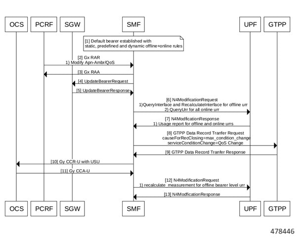
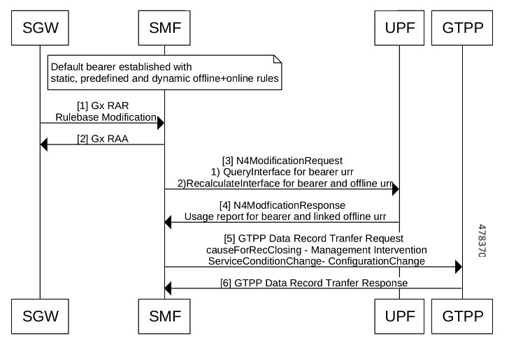
Added support for:

  • Asynchronus and Synchronous Usage Report for Offline Bearer Recalculation

  • Handling Modify Bearer Request Trigger on the Gz Interface

  • Gz Change Notification

  • Default Bearer Modification based on APN-AMBR and Qci change

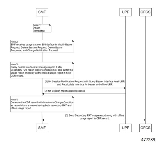
  • Handling Periodic Report of Secondary RAT Usage:

  • EGCDR final record configuration

  • Zero CDR suppression

  • Final Unit Indication in subsequent CCR-U

  • FHT Continue Enhancement

  • Diameter Credit-Control-Failure-Handling AVP

2023.04.0

Added support for:

  • Multiple 3GPP specification compliance for SMF interfaces.

  • Gz Interfaces and associated features:

    • PDN Attach and Detach with Gz Interface

    • Gz Usage Reporting

  • Indirect communication for NFs through SCP Model D.

  • Excluding the optional IE for Locality in the NRF messages.

2023.03.0

Added support for:

  • Gx interfaces and their associated features:

    • Gx initial attach and detach

    • Dynamic and predefined rule

  • Gy interfaces and their associated features:

    • Gy usage reporting

    • Gy failure handling

    • Gy MSCC level failure result codes

    • Gy QVT and QHT

    • Gy tarrif time

  • IPv6 on data interfaces

2023.02.0

Added support for:

  • N4 interface over IPsec

  • IPv6 address on all SMF interfaces

  • User plane integrity protection

  • Mutual TLS for the SBI interface

  • 3GPP specification version compliance configuration for CHF server

2022.04.0

Added support for configuration-based control of UDM and PCF messages.

2021.02.3.t3

Added support for N2 cause and diagnostic IEs.

2021.02.3

Added support for:

  • Cause IE on the N11 interface.

  • NAS messages compliance with invalid protocol data handling.

  • ProblemDetails JSON object on the N11 interface.

  • Error handling with HTTP error codes.

  • HTTP/2 TLS support for the SBA interface.

2021.02.0

First introduced.

Pre-2020.02.0

Feature Description

Table 3. Feature History
Feature Name

Release Information

Description

Dual Stack Support on N3

2024.01

SMF enables the dual stack transport for the N3 tunnel using the dual-stack-transport { false | true } CLI command in the UPF network profile.

Default Setting: Disabled – Configuration Required


Important


The PGW-C term used in this chapter denotes the EPS interworking functionality supported by SMF and must not be assumed as a standalone P-GW that is used in the LTE network.


In the 5G System Architecture, the SMF performs the session management functions that the 4G Mobility Management Entity (MME), Serving Gateway Control plane function (SGW-C), and PDN Gateway Control plane function (PGW-C) handle. The SMF is one of the elements of the Service-Based Architecture (SBA). SMF is responsible for communicating with the decoupled data plane, creating, updating, and removing Protocol Data Unit (PDU) sessions. SMF also manages the session context with the User Plane Function (UPF). For the session management-related functions, SMF communicates with various interfaces, such as N1, N4, and N10.

At a given time, the SBI interfaces (N7, N10, N11, and N40) support only an IPv4 or IPv6 address. However, the N3, N4 and GTPC interfaces support either IPv4 or IPv6 address or both. For the IP address support, both the endpoint and interfaces configuration must include a unique VIP IP and port. For configuration details, see the Configuring Interfaces section.

SMF prioritizes IPv6 over IPv4 addresses while initiating a message on the N4 interface. If the peer GTPC uses both IPv4 and IPv6 addresses, SMF uses the same IP address type on which it has received the last message from the GTPC peer for that particular session, while initiating any new message.

If SMF receives both the IPv4 and IPv6 address as part of a CSR or MBR message, SMF sends an echo using an IPv4 and IPv6 address on the GTPC interface. The peer is considered to be down, only if echo fails on both the interfaces. SMF determines it as path failure and clears the session.

For SBI interfaces, if the discovered NF profile contains both IPv4 and IPv6 addresses, then SMF selects the IP to communicate with the peer NF based on the IP type configuration at SBI endpoint level or interface level for that particular interface.

SMF negotiates between UPF tunnel and RAN by exchanging the IPv6 endpoint identifier information and tunnel information for both.

During HO, SMF creates the tunnel based on the tunnel information received from the target peer and exchanges the tunnel information between UPF and the target peer.

Each interface and endpoint can be independently configured for IPv4 or IPv6 or both based on the current support.

During UPF association setup, the SMF checks if the transport type in the setup request is the same as the configured address. The SMF proceeds with the association request or rejects the request based on the validation result.

Similarly, during NRF discovery, the transport type must match the statically configured transport type either at the endpoint level or interface level. The SMF performs NF selection based on the IP address-matching criteria.

For 4G calls with legacy interfaces, peer SGW IPv4, IPv6, or IPv4v6 data address is supported.


Note


DNS, RADIUS, and roaming interfaces currently don’t support the IPv6 address.


3GPP Specification Compliance for SMF Interfaces

Feature Description

The SMF supports configuring any two 3GPP specification compliance versions 15.x (December 2018 and June 2019) for the SMF interfaces N1, N2, N4, N7, N10, N11, N40, and Nnrf. It processes the incoming messages from the peer interfaces in compliance with the profiles configured for the corresponding services.

For more information on a various supported specification versions and the corresponding mapped URI versions for various interfaces, see Standards Compliance section.

For information on the compliance profile configurations, see the Configuring 3GPP Specification Compliance for Interfaces section.

The SMF supports only the IE encoding and decoding functionalities. The existing features work with the June 2019 specification versions. No additional features in the June 2019 version are supported.


Note


The SMF continues to support the older versions of 3GPP specifications, and the compliance profile configuration controls the same for the SMF interfaces.


URI Version Selection Logic

When two different 3GPP compliance versions are configured, the Nnrf_NFDiscovery service allows SMF to discover other NF (Network Function) instances with the services they offer, by querying the local NRF (Network Repository Function), i.e CHF, AMF, and PCF.

The Discovery response SearchResult body contains an array of NF Profile objects that satisfy the search filter criteria. The attribute data type NFServiceVersion captures the versions supported by various peer NFs.

Based on SMF profile configuration versions and the version received in the Discovery SearchResult, the SMF selects a version for peer NFs for subsequent messages.

The logic based on which the SMF selects the versions for peer NFs, is called the URI Version Selection Logic. It selects the highest version for the peer NFs.

The following table describes how the URI version selection logic selects a suitable version for peers upon receiving the NFServiceVersion as a result of the Discovery response:

Table 4. URI Selection Logic
SMF Compliance Configuration Versions Discovery Search Result Versions Selected Version for Peer NFs

V2, V1

V2, V1

V2

V2, V1

V1

V1

V1

V2, V1

V1

Once the version for peer NFs is selected, the subsequent message is sent using the selected version. If during the first message exchange the selected peer NF goes down, the SMF selects another peer with the same or next highest NF version.

After the first message exchange if the selected peer NFs go down, the SMF will not select another peer with the same or different version for the session.

Standards Compliance

The SMF is one of the Control Plane (CP) NFs of the 5G core network. The SMF uses different interfaces to communicate with the other NFs or nodes.

For example, the N4 interface exists between the SMF and User Plane Function (UPF). Each SMF interface complies with a specific version of the 3GPP specification, depending on the supported compliance version.

Use the following table to determine the compliance mapping of each SMF interface and the 3GPP Standards specification versions.

Table 5. SMF Interface and 3GPP Standards Specification Version Map
Interface Relationship 3GPP Specification Version

N1/NAS

Between UE and AMF

24.501

For December 2018 Compliance Support: 15.2.0

For June 2019 Compliance Support: 15.4.0

Supported Specifications: 15.2.0, 15.4.0

Mapped URI: V1

N2/NGAP

Between RAN and AMF

38.413

For December 2018 Compliance Support: 15.2.0

For June 2019 Compliance Support:15.4.0

Supported Specifications: 15.0.0, 15.2.0, 15.4.0

Mapped URI: V1

N4

Between UPF and SMF

29.244

For December 2018 Compliance Support: 15.2.0

For June 2019 Compliance Support: 15.4.0

N7

Between PCF and SMF

29.512

For December 2018 Compliance Support: 15.2.0

For June 2019 Compliance Support: 15.4.0

Supported Specifications: 15.0.0, 15.2.0, 15.4.0

Mapped URI: V1

N10

Between UDM and SMF

29.503

For December 2018 Compliance Support: 15.2.1

For June 2019 Compliance Support: 15.4.0

Supported Specifications: 15.1.0,1 5.2.1, 15.4.0

Mapped URI:

  • V1: 15.1.0, 1 5.2.1

  • V2: 15.4.0

N11

Between AMF and SMF

29.518

29.502

For December 2018 Compliance Support: 15.2.0

For June 2019 Compliance Support: 15.4.0

Supported Specifications: 15.0.0, 15.2.0, 15.4.0

Mapped URI: V1

N40

Between SMF and CHF

32.291

For December 2018 Compliance Support: 15.1.0

For June 2019 Compliance Support: 15.3.0

Supported Specifications: 15.0.0,15.1.0, 15.2.1, 15.3.0, 15.3.0.custom, 15.3.0.std

Mapped URI:

  • V1: 15.0.0, 15.1.0

  • V2 15.2.1, 15.3.0, 15.3.0 std, 15.3.0 custom

Nnrf

Between NRF and SMF

29.510

For December 2018 Compliance Support: 15.0.0

For June 2019 Compliance Support: 15.4.0

Supported Specifications: 15.0.0, 15.2.0, 15.4.0

Mapped URI: V1

Configuring 3GPP Specification Compliance for Interfaces

To configure the SMF interfaces in compliance with the 3GPP specifications, use the following sample configuration:

config 
   profile compliance profile_name 
       service { n1 | n2 | namf-comm | nchf-convergedcharging | nnrf-disc | nnrf-nfm | npcf-smpolicycontrol | nsmf-pdusession | nudm-sdm | nudm-uecm | threegpp23502 } 
          version { full version_format| spec spec_version| uri uri_version } 
          version-list version  version_name { full version_format | mode { active | offline } | spec  spec_version | uri  uri_version } 
          end 
       end 
   end 

Important


Service selection is based only on the specification version. In future releases, the full API version will be used.


NOTES:

  • service { n1 | n2 | namf-comm | nchf-convergedcharging | nnrf-disc | nnrf-nfm | npcf-smpolicycontrol | nsmf-pdusession | nudm-sdm | nudm-uecm | threegpp23502 } —Specify the service names as cited in the 3GPP TS 29.510 version 15.2.0, section 6.1.6.3.11.


    Note


    The compliance profile configuration for the nchf-convergedcharging service supports the 3GPP TS 29.510 version 15.4.0 specification. With this configured version, the SMF sends the subscriberIdentifier in the following format to CHF:

    "subscriberIdentifier":"imsi-123456789"


  • version —Specify the compliance version name to be configured. It allows configuring only one version at a time.

  • full version_format —Specify the API full version for each service in the following format:

    <Major-version>.<Minor-version>.<patch-version>.[alpha-<draft-number>]

    The format is specified in the 3GPP TS 29.501 version 15.2.0, section 4.3.1.1.

  • spec spec_version —Specify the 3GPP specification version number, which is one of the following values:

    • 15.0.0

    • 15.1.0

    • 15.2.0

    • 15.2.1

    • 15.3.0

    • 15.3.0.custom

    • 15.3.0.std

    • 15.4.0

    For example, to support 3GPP June 2019 specification compliance for the N7 (PCF) interface, configure the specification version as 15.4.0.

    The default version number depends on the SMF interface. For example, the default version is 15.2.0 for the N7 interface. Similarly, for the N10 interface, the default version is 15.2.1.

  • uri uri_version —Specify the API version URI for each service in the following format:

    v—Concatenated with a number, where the value can be both v1 and v2, or either v1 or v2.

    Examples:

    —For the compliance version 15.4.0 in the NRF configuration for the service type nudm-sdm, mandate the configuration of the uri-version in the version to v2. For the compliance version 15.2.1, this configuration is optional.

    —version v1: (- url: '{apiRoot}/nsmf-pdusession/v1').

  • version-list version version_name —Specify the list of compliance versions of the 3GPP specification. If the version-list version is configured with only one version, then both version and version-list version CLIs are considered for version selection logic for peer NFs. Both the CLIs version and version-list version allow configuring the same set of attributes.


    Note


    version-list version is supported for only for N1, N2, N7, N10, N11, N40, and Nnrf interfaces.


  • mode { active | offline } —Specify the status of configured 3GPP compliance versions. mode is an optional configuration under the CLI version-list version . The default value of mode is active . If version-list version is configured with two versions, then at least one version should be active .


Important


Configuring the 3GPP specification version value depends on the SMF interface. Not all the preceding versions are options for the SMF interfaces. Only a combination of the preceding versions exists as an option for the 3GPP version compliance configuration. For details on the compliance version, see the Standards Compliance section.


Important


The 15.3.0.custom spec version is customer specific and applicable only to the nchf-convergedcharging service. For more details, contact your Cisco account representative.

In this spec version, the MultipleUnitUsage attribute sends the usedUnitContainer field in upper case. For all other spec versions post 15.3.0, the MultipleUnitUsage attribute sends the UsedUnitContainer field in lower case.


Important


The release version 2023.03.0 supports both version and version-list version CLIs. However, the version CLI will be discontinued from the future releases.


Configuration Verification

To verify if the 3GPP specification profile compliance is configured, use the following show full-configuration profile smf command:

[smf] smf(config)# show full-configuration profile smf 
profile smf smf1
 locality      LOC1
 instances 1 allowed-nssai [ slice1 ]
 instances 1 fqdn cisco.com.apn.epc.mnc456.mcc123 node-id abcdef
 plmn-list mcc 123 mnc 456
 exit
 plmn-list mcc 242 mnc 01
 exit
 plmn-list mcc 310 mnc 210
 exit
 plmn-list mcc 310 mnc 220
 exit
 plmn-list mcc 310 mnc 260
 exit
 plmn-list mcc 310 mnc 310
 exit
 plmn-list mcc 440 mnc 550
 exit
 service name nsmf-pdu
  type               pdu-session
  schema             http
  service-id         1
  version            1.Rn.0.0
  http-endpoint base-url http://smf-service
  icmpv6-profile     icmpprf1
  compliance-profile comp1 
  access-profile     access1
  subscriber-policy  polSub
 exit
exit

To verify the configuration, use the show full command in the 3GPP specification profile compliance configuration mode:

product smf(config-compliance-comp1)# show full
profile compliance comp1 
   service nsmf-pdusession
      version uri v1
      version full 1.0.0
      version spec 15.2.0

Supported SMF Interfaces

This section describes the different interfaces that SMF uses to facilitate communication with other network functions.

GTP Interface

General Packet Radio Service (GPRS) Tunneling Protocol (GTP) is the primary protocol used in a GPRS core network through 3G, 4G, or 5G networks. The GTP is responsible for signaling and transporting mobile data within the core network.

The GTP uses the N9 interface as the reference point between two core user plane functions (UPFs).

GTP Cause Code Handling

Feature Description

The SMF supports the GTP cause code handling for 4G procedures when it detects any failure with IEs.

Create Session Request

The SMF supports the following causes in the Create Session Request message.

Table 6. Supported Causes in Create Session Request

Cause

SMF Behavior

Missing or unknown APN

If the configured DNN does not match the DNN received in the Create Session Request, then the SMF rejects the message with this cause value in the Create Session Response and sets the appropriate disconnect reason.

User authentication failed

If the SMF receives a failed AAA secondary authentication response from RADIUS, then SMF rejects the message with this cause value in Create Session Response. This cause indicates that the request is rejected due to failure in authentication or security procedure and sets the appropriate disconnect reason.

APN access denied – no subscription

If the SMF receives the subscription fetch failure response from the UDM, then the SMF rejects the message with this cause value in the Create Session Response. This cause indicates that the SMF has denied the user access to an APN because the subscriber does not have the necessary subscription. SMF also sets the appropriate disconnect reason.

New PDN type due to single address bearer only

If the Dual Address Bearer Flag (DAF) indication is not set and the requested PDN-type is IPV4V6 in Create Session Request message, then the SMF rejects the message with this cause value in Create Session Response. SMF also sets the appropriate disconnect reason.

Late Overlapping Request

The Create Session Request message includes the Origination Time Stamp indicating the absolute time at which the request is initiated (as specified in clause 13.2.2, TS29.274).

If SMF receives any subsequent CSR from different S-GW and different sequence number with older timestamp in "Origination Time Stamp" than the time stamp stored for the existing session, then SMF rejects the new CSR with this cause value in Create Session Response. This cause indicates the incoming request collides with an existing session that does not have a recent time stamp than the time stamp of the new request.

If the timestamp is newer, then SMF aborts the current procedure and handles the new CSR request with the recent time stamp.

Timed Out Request

If the incoming CSR received origination-time-stamp and maximum-wait-time IEs, SMF starts the SLA timer with maximum-wait-time value at the start of the Create procedure and aborts the Create procedure on expiry of the timer. Then SMF rejects with this cause value in CSR Response.

New PDN type due to network preference

If the session type configured under profile dnn is IPv4 or IPv6, and the requested PDN type coming in Create Session Request is IPv4v6, then SMF rejects the message with this cause value in Create Session Response.

Delete Bearer Request

The SMF supports the following causes in the Delete Bearer Request message.

Table 7. Supported Causes in Delete Bearer Request

Cause

Scenario

Reactivation required

SMF sends Delete Bearer Response for default bearer with this cause value in the following cases:

  • CHF reconciliation

  • PCF reconciliation

  • Internal DB conflict

  • Session Report with SRSR/GTER/SRIR/SPTER/ERIR

PDN connection inactivity timer expires

SMF sends Delete Bearer Response for default bearer with this cause value in the following cases:

  • CP-IDLE timer expiry

  • Session Report with UPIR

  • Absolute Timer Expiry

RAN/NAS Cause IE

SMF receives the RAN/NAS Cause IE from access network in the GTP messages due to QoS flow termination or PDU session termination. SMF provides the received cause in the ranNasRelCauses attribute of the RuleReport to PCF. For more information about this cause, see the 3GPP TS 29.274 version 15.4.0.

The RAN/NAS Cause IE supports the following GTP messages:

  • Create Bearer Response

  • Update Bearer Response

  • Delete Bearer Command

  • Delete Session Request

Spec-Derived Cause Code Mapping

The SMF supports specification derived (TS 29.524) cause code mapping for 5G messages for UDM and PCF interfaces.

Table 8. Mapping from HTTP to 5GSM cause values—Request rejected by UDM due to N10 failures

HTTP Status Code on N10

Protocol or Application Error

5GSM Cause to UE

403 Forbidden

ROAMING_NOT_ALLOWED

Cause #29—User authentication or authorization failed

DNN_NOT_ALLOWED

Cause #27—Missing or unknown DNN

404 Not Found

USER NOT FOUND

Cause #29—User authentication or authorization failed

Table 9. Mapping from HTTP to 5GSM cause values—Request rejected by PCF

HTTP Status Code on N7

Protocol or Application Error

5GSM Cause to UE

400 Bad Request

USER_UNKNOWN

Cause #29—User authentication or authorization failed

ERROR_INITIAL_PARAMETERS

Cause #31—Request rejected, unspecified

ERROR_TRIGGER_EVENT

Cause #31—Request rejected, unspecified

403 Forbidden

ERROR_TRAFFIC_MAPPING_ INFO_REJECTED

Cause #29—User authentication or authorization failed

ERROR_CONFLICTING_REQUEST

Cause #67—insufficient resources for specific slice and DNN

POLICY_CONTEXT_DENIED

Cause #29—User authentication or authorization failed

VALIDATION_CONDITION_ NOT_MET

Cause #29—User authentication or authorization failed

Standards Compliance

The supported GTP cause codes comply with the following standards:

  • 3GPP TS 29.274, Version 15.4.0

  • 3GPP TS 29.524

Configuring GTP Cause Codes

This section describes how to configure cause-to-class mapping and class-to-cause mapping.

For source interface failures, the cause-map-class profile determines which class-map-cause profile must be applied on the corresponding target interface, only if the latter is configured under access profile. The respective CLI configurations send the user-defined cause values to the target interface based on the source interface failures and cause values. If the CLI commands are not configured, the target interface sends the spec-driven cause values as default values.

Configuring the GTP cause codes involves the following steps:

Cause to Class Mapping Configuration

This section describes how to configure cause to class mapping in SMF.

Configuring Cause-to-Class Map under cause-map-class Profile

To configure cause-to-class mapping under the cause-map-class profile, use the following sample configuration:

config 
   profile cause-map-class nf-type [ udm | pcf ] cmc_profile_name 
      source { status-code httpv2_code cause cause_value } fail-class failclass_string 
      exit 

NOTES:

  • profile cause-map-class nf-type [ udm | pcf ] cmc_profile_name : Specify the NF profile name to configure the cause-map-class profile.

  • source { status-code httpv2_code cause cause_value } fail-class failclass_string

    • status-code httpv2_code : Specify the HTTPv2 status code of the source interface.

    • cause cause_value : Specify the cause value as a string.

    • fail-class failclass_string : Specify the failure class as a string.

  • The profile cause-map-class is associated to the network-element profile.

  • The status-code and cause keywords are optional. If both are configured, then the corresponding fail-class is given higher priority followed by status-code and cause .

Example

The following is an example of the UDM interface configuration:

profile cause-map-class nf-type udm UDM-CMC
     source status-code 403 cause DNN_NOT ALLOWED fail-class congestion
Configuring Cause-to-Class Map under Network-Element Profile

To configure cause-to-class mapping under the network-element profile, use the following sample configuration:

config 
   profile network-element [ udm | pcf ] nfprofile_name 
      cause-map-class-profile cmcp_name 
      exit 

NOTES:

  • profile network-element [ udm | pcf ] nfprofile_name : Specify the NF profile name to configure the network-element profile.

  • cause-map-class-profile cmcp_name : Specify the cause-to-class map profile name.

Example

The following is an example of the UDM interface configuration:

profile network-element udm nfprf-udm
     cause-map-class UDM-CMC
Sample Configuration
[smf] smf# show running-config profile cause-map-class
profile cause-map-class nf-type udm CMC-UDM-1
 source status-code 500 cause CAUSE2 fail-class failClass2
 source status-code 500 cause CAUSE3 fail-class failClass3
 source status-code 501 cause CAUSE1 fail-class failClass1
 source status-code 502 cause CAUSE2 fail-class failClass1
 source status-code 504 cause CAUSE4 fail-class failClass4
 source status-code 505 cause CAUSE4 fail-class failClass5
exit
profile cause-map-class nf-type udm CMC-UDM-2
 source status-code 501 cause CAUSE1 fail-class failClass6
 source status-code 501 cause any fail-class failClass6
 source status-code 502 cause CAUSE1 fail-class failClass6
 source status-code 502 cause CAUSE2 fail-class failClass6
 source status-code 502 cause any fail-class failClass6
 source status-code any cause CAUSE1 fail-class failClass6
 source status-code any cause CAUSE2 fail-class failClass6
exit
profile cause-map-class nf-type udm CMC-UDM-3
 source status-code 504 cause CAUSE4 fail-class failClass4
 source status-code 505 cause CAUSE4 fail-class failClass5
exit
profile cause-map-class nf-type pcf PCF-CMC-1
 source status-code 500 cause CAUSE2 fail-class failClass2
 source status-code 500 cause CAUSE3 fail-class failClass3
 source status-code 501 cause CAUSE1 fail-class failClass1
 source status-code 502 cause CAUSE2 fail-class failClass1
 source status-code 504 cause CAUSE4 fail-class failClass4
 source status-code 505 cause CAUSE4 fail-class failClass5
exit
profile cause-map-class nf-type pcf PCF-CMC-2
 source status-code 500 cause any fail-class failClass2
 source status-code 501 cause any fail-class failClass3
 source status-code any cause CAUSE2 fail-class failClass2
 source status-code any cause CAUSE3 fail-class failClass3
exit
[smf] smf#
Class to Cause Mapping Configuration

This section describes how to configure class to cause mapping in SMF.

Configuring Class-to-Cause Map under class-map-cause Profile

To configure class-to-cause mapping under the class-map-cause profile, use the following sample configuration:

config 
   profile class-map-cause cmc_profile_name 
      fail-class failclass_string 
         target n11 { status-code  httpv2_code cause cause_value } | [ n1 | n2 | gtp ] { cause cause_value } 
         exit 

NOTES:

  • profile class-map-cause cmc_profile_name : Specify the profile name to configure class-map-cause.

  • fail-class failclass_string : Specify the failure class as a string.

  • target n11 { status-code httpv2_code cause cause_value } | [ n1 | n2 | gtp ] { cause cause_value } :

    • target : Specify the target interface.

    • status-code httpv2_code : Specify the HTTPv2 status code for the target interface.

    • cause cause_value : Specify the cause value for the target interface.

  • The profile class-map-cause is associated to the access profile.

  • The status-code keyword is not applicable to the GTP, N1, and N2 interfaces.

Example

The following is an example of the CLI configuration:

profile class-map-cause cmc1
    fail-class congestion
         target gtp cause 72
Configuring Class-to-Cause Map under Access Profile

To configure class-to-cause mapping under the access profile, use the following sample configuration:

config 
   profile access access_profile_name 
      [ gtpc | n1 | n2 | n11 ] class-map-cause-profile cmc_profile_name 
      exit 

NOTES:

  • profile access access_profile_name : Specify the profile name to configure the access profile.

  • class-map-cause-profile cmc_profile_name : Specify the profile name to configure the class-to-cause map profile.

Example

The following is an example of the CLI configuration:

profile access access1
       n11 class-map-cause cmc1
Sample Configuration
[smf] smf# show running-config profile class-map-cause
profile class-map-cause CMC
 fail-class failClass1
  target n11 status-code 403 cause CA1
  target n1 cause CA_N1
  target n2 cause CA_n2
  target gtp cause 75
 exit
 fail-class failClass2
  target n11 status-code 402 cause CAUSE4
  target n1 cause CAUSE3
  target n2 cause CAUSE2
  target gtp cause 95
 exit
exit
[smf] smf#
GTP Cause Code Handling OAM Support

This section describes operations, administration, and maintenance information for this feature.

Statistics Support

The source interface failures support the following disconnect reasons:

  • disc_new_pdn_type_due_to_single_addr_bearer_only—The number of Create Session Request failures with cause value "New PDN type due to single address bearer only" in Create Session Response.

  • disc_new_pdn_type_due_to_network_preference—The number of Create Session Request failures with cause value "New PDN type due to network preference" in Create Session Response.

  • disc_pdnsetup_dnn_missing_or_unknown—The number of Create Session Request failures with cause value "Missing or unknown APN" in Create Session Response.

  • disc_request_timeout_at_originating_entry—The number of Create Session Request failures with cause value "Timed Out Request" in Create Session Response.

GTPv2 IE and Cause Codes

Feature Description

This section describes the GPRS Tunneling Protocol, Version 2 (GTPv2) IEs and cause codes for 4G and 5G procedures.

Cause Source Errors

The Cause Source (CS) bit supports the following cause values in Create Session Response, Modify Bearer Response, Modify Bearer Failure Indication (MBFI), or Delete Bearer Failure Indication (DBFI).

Table 10. CS Bit Causes

Cause Value

Scenario

Context Not Found

When the subscriber is not present in SMF and receives Create Session Response with handover indication, the SMF sends this cause.

Missing Or Unknown APN

When Create Session Response receives missing or unknown APN, the SMF sends this cause.

DBFI with Context Not Found

When the subscriber is not present in SMF and receives Delete Bearer Command, the SMF sends this cause.

Delete Session Response with Context Not Found

When the subscriber is not present in SMF and receives a Delete Session Request in old TEID, the SMF sends this cause.

Bearer Context IE Errors

The Bearer Context IE Error (BCE) bit supports the following cause values in Delete Session Response, Modify Bearer Response, Modify Bearer Failure Indication (MBFI), or Delete Bearer Failure Indication (DBFI).

Table 11. BCE Bit Causes

Cause Value

SMF Behavior or Scenario

MBFI with Context Not Found

When SMF receives Modify Bearer Request with a wrong EBI in bearer context, the SMF sends this cause.

DBFI with Context Not Found

When SMF receives Delete Bearer Command with a wrong EBI in bearer context, the SMF sends this cause.

Remote Node Errors

SMF supports the following remote node errors:

  • Context not found

  • Missing or unknown APN

  • PduSessionType

  • Mandatory IE missing

  • Malformed message errors

Statistics Support
smf_gtpc_msg_stats

This feature supports the following statistics related to GTPC messages:

Description: Stats for GTPC interface messages

Sample Query: 'smf_gtpc_msg_stats{message_type="modify_bearer_request"}'

Labels:

  • Label: message_type

    Label Description: GTPC Message Type

    Example: modify_bearer_request, delete_bearer_request, delete_session_request

  • Label: status

    Label Description: GTPC message status

    Example: attempted, success, failures

  • Label: reason

    Label Description: The reason associated with the failure

    Example: ipc_failed, sgw_failure, EGTP_CAUSE_LOCAL_DETACH, EGTP_CAUSE_RAT_CHANGED_FROM_3GPP_TO_NON_3GPP, EGTP_CAUSE_COMPLETE_DETACH, EGTP_CAUSE_ISR_DEACTIVATION, EGTP_CAUSE_ERROR_IND_RCVD_RNC_ENODE, EGTP_CAUSE_IMSI_DETACH_ONLY, EGTP_CAUSE_REACTIVATION_REQUESTED, EGTP_CAUSE_PDN_RECONNECTION_TO_THIS_APN_DISALLOWED, EGTP_CAUSE_ACCESS_CHANGED_FROM_NON_3GPP_TO_3GPP, EGTP_CAUSE_PDN_CONN_INACTIVITY_TIMER_EXPIRED, EGTP_CAUSE_PGW_NOT_RESPONDING, EGTP_CAUSE_NETWORK_FAILURE, EGTP_CAUSE_QOS_PARAMETER_MISMATCH, EGTP_CAUSE_REQ_ACCEPTED, EGTP_CAUSE_REQ_ACCEPTED_PARTIALLY, EGTP_CAUSE_NEW_PDN_TYPE_NETWORK_PREFERENCE, EGTP_CAUSE_NEW_PDN_TYPE_SINGLE_ADDR_BEARER_ONLY, EGTP_CAUSE_CONTEXT_NOT_FOUND, EGTP_CAUSE_INVALID_MESSAGE_FORMAT, EGTP_CAUSE_VERSION_NOT_SUPPORTED_BY_NEXT_PEER, EGTP_CAUSE_INVALID_LENGTH, EGTP_CAUSE_SERVICE_NOT_SUPPORTED, EGTP_CAUSE_MANDATORY_IE_INCORRECT, EGTP_CAUSE_MANDATORY_IE_MISSING, EGTP_CAUSE_SYSTEM_FAILURE, EGTP_CAUSE_NO_RESOURCES_AVAILABLE, EGTP_CAUSE_SEMANTIC_ERROR_IN_TFT_OPERATION, EGTP_CAUSE_SYNTACTIC_ERROR_IN_TFT_OPERATION, EGTP_CAUSE_SEMANTIC_ERROR_IN_PKT_FILTERS, EGTP_CAUSE_SYNTACTIC_ERROR_IN_PKT_FILTERS, EGTP_CAUSE_MISSING_OR_UNKNOWN_APN, EGTP_CAUSE_UNEXPECTED_REPEATED_IE, EGTP_CAUSE_GRE_KEY_NOT_FOUND, EGTP_CAUSE_REALLOCATION_FAILURE, EGTP_CAUSE_DENIED_IN_RAT, EGTP_CAUSE_PREFERRED_PDN_TYPE_UNSUPPORTED, EGTP_CAUSE_ALL_DYNAMIC_ADDR_OCCPUPIED, EGTP_CAUSE_UE_CTX_WO_TFT_ALREADY_ACTIVATED, EGTP_CAUSE_PROTOCOL_TYPE_NOT_SUPPORTED, EGTP_CAUSE_UE_NOT_RESPONDING, EGTP_CAUSE_UE_REFUSES, EGTP_CAUSE_SERVICE_DENIED, EGTP_CAUSE_UNABLE_TO_PAGE_UE, EGTP_CAUSE_NO_MEMORY_AVAILABLE, EGTP_CAUSE_USER_AUTHENTICATION_FAILED, EGTP_CAUSE_APN_DENIED_NO_SUBSCRIPTION, EGTP_CAUSE_REQUEST_REJECTED, EGTP_CAUSE_PTMSI_SIGNATURE_MISMATCH, EGTP_CAUSE_IMSI_IMEI_NOT_KNOWN, EGTP_CAUSE_SEMANTIC_ERROR_IN_TAD_OPERATION, EGTP_CAUSE_SYNTACTIC_ERROR_IN_TAD_OPERATION, EGTP_CAUSE_RESERVED_MESSAGE_VALUE_RECEIVED, EGTP_CAUSE_PEER_NOT_RESPONDING, EGTP_CAUSE_COLLISION_WITH_NETWORK_INIT_REQUEST, EGTP_CAUSE_UNABLE_TO_PAGE_UE_DUE_TO_SUSPENSION, EGTP_CAUSE_CONDITIONAL_IE_MISSING, EGTP_CAUSE_INCOMPATIBLE_APN_REST_TYPE, EGTP_CAUSE_INVALID_LENGTH_WITH_PIGGYBACK_MSG, EGTP_CAUSE_DATA_FORWARDING_NOT_SUPPORTED, EGTP_CAUSE_INVALID_REPLY_FROM_REMOTE_PEER, EGTP_CAUSE_FALLBACK_TO_GTPV1, EGTP_CAUSE_INVALID_PEER, EGTP_CAUSE_TEMP_REJECTED_DUE_TO_HANDOVER_IN_PROGRESS, EGTP_CAUSE_REQ_REJECTED_FOR_PMIPV6_REASON, EGTP_CAUSE_APN_CONGESTION, EGTP_CAUSE_BEARER_HANDLING_NOT_SUPPORTED, EGTP_CAUSE_UE_ALREADY_REATTACHED, EGTP_CAUSE_MULTI_PDN_CONNECTION_FOR_APN_NOT_ALLOWED, EGTP_CAUSE_MME_SGSN_REFUSES_DUE_TO_VPLMN_POLICY, EGTP_CAUSE_GTPC_ENTITY_CONGESTION, EGTP_CAUSE_TARGET_ACCESS_RESTRICTED_FOR_THE_SUBSCRIBER, EGTP_CAUSE_UE_TEMP_NOT_REACHABLE_DUE_TO_POWER_SAVING, EGTP_CAUSE_RELOC_FAILURE_DUE_TO_NAS_MSG_REDIRECTION, EGTP_CAUSE_MISSING_TIMESTAMP_OPTION, EGTP_CAUSE_MULTIPLE_HNP_NOT_ALLOWED, EGTP_CAUSE_SN_MALFORMED_MSG, EGTP_CAUSE_INT_TIMEOUT

  • Label: qos_5qi

    Label Description: 5Qi applicable for the QoS flow

    Example: 1, 2, 5

  • Label: rat_type

    Label Description: Type of the radio access associated with the request

    Example: EUTRA, NR, WLAN, rat_type_unknown

  • Label: smf_current_procedure

    Label Description: Current Procedure Name for Message Level Stats

    Example: nr_to_untrusted_wifi_handover, eps_fb_ded_brr, PdnDisconnectProcedure, enb_to_untrusted_wifi_handover, pcf_req_ded_brr_create, pcf_req_ded_brr_delete, pcf_req_ded_brr_mod, smf_initiated_pdn_detach, untrusted_wifi_to_enb_handover, upf_sess_report_srir_sess_rel, utn3gpp_to_5g_handover

Gx Interface

The Gx interface is an interface between SMF and Policy and Charging Rules Function (PCRF).

This section describes about the Gx support on the SMF. It includes the details of all the AVPs supported over the Gx interface.

Feature Description

The policy control and charging (PCC) architecture allows operators to perform service-based QoS policy and flow based charging control. The PCC provides access control, resource control, and QoS control.

How it Works

The Gx support for SMF uses the following two main elements in the PCC architecture.

  • PCEF (Policy enforcement functionality within SMF)

  • PCRF (Policy and charging rules function)

Gx reference point lies between the PCRF and the SMF. The Gx reference point allows the provisioning and removal of PCC rules. The following diagram shows the reference points between various elements involved in the policy infrastructure.

Figure 1. Gx Interface

The Gx interface implementation is a part of the diameter connection. The Gx messages commonly involve installing/removing dynamic rules and activating/deactivating predefined rules, and modifying APN-AMBR and Default Bearer QoS.

Associating a rule with a bearer is the task of ‘bearer binding’. The PCEF performs this task in SMF. The binding mechanism is the procedure that associates a service data flow. The flow is defined in a PCC rule by the SDF template to the IP-CAN bearer (deemed to transport the service data flow).

  • PCEF bearer binding: The PCEF binds a rule to a bearer. This rule may require to perform a bearer activation or update. The SMF service performs the task of updating or creating a new Bearer. This update happens by invoking the UBR or CBR request towards SGW/MME.


    Note


    In the current release, PCEF binding only for default bearer is supported.


Gx Initial Attach and Detach Support

Following are the various types of rules associated with the Gx initial attach and detach support for SMF:

  • PCC Rules: As a part of the initial attach. The PCEF supports:

    • Installation of the dynamic rules using Charging-Rule-Definition AVP

    • Predefined rules using Charging-Rule-Name AVP

    • Bearer binding to the default bearer


    Note


    The CBR procedure and UBR for TFT updates on default bearer is not supported in current release.


  • Rulebase Selection: PCEF supports the processing of the Charging-Rule-Base-Name AVP. The processing happens as a part of CCA-I and overwrites the ECS rulebase name configuration as part of DNN.

  • APN-AMBR: The APN-AMBR values as a part of Qos-Information AVP by PCRF during the CCA-I/CCA-U/RAR are processed and applied on the call.

  • Default Bearer QoS: The values authorized by PCRF using Default-EPS-Bearer-QoS AVP during the CCA-I/CCA-U/RAR are processed and applied on the call.

Following are the AVPs supported over Gx (CCR/CCA/RAR/RAA) interface for SMF:

  • Origin-Host

  • Origin-Realm

  • Destination-Realm

  • CC-Request-Type

  • CC-Request-Number

  • Destination-Host

  • Subscription-Id

    • Subscription-Id-Type

    • Subscription-Id-Data

  • Supported-Features

    • Vendor-Id

    • Feature-List-ID

    • Feature-List

  • Network-Request-Support

  • Framed-IP-Address

  • Framed-IPv6-Prefix

  • IP-CAN-Type

  • 3GPP-RAT-Type

  • Termination-Cause

  • User-Equipment-Info

    • User-Equipment-Info-Type

    • User-Equipment -Info-Value

  • QoS-Information

    • APN-Aggregate-Max-Bitrate-UL

    • APN-Aggregate-Max-Bitrate-DL

  • Default-EPS-Bearer-QoS

    • QoS-Class-Identifier

    • Allocation-Retention-Priority

      • Priority-Level

      • Pre-Emption-Capability

      • Pre-Emption-Vulnerability

  • AN-GW-Address

  • 3GPP-SGSN-MCC-MNC

  • 3GPP-User-Location-Info

  • 3GPP-MS-TimeZone

  • Called-Station-Id

  • Bearer-Usage

  • Online

  • Offline

  • Charging-Rule-Report

    • Charging-Rule-Name

    • Charging-Rule-Base-Name

    • PCC-Rule-Status

    • Rule-Failure-Code

  • Event-Trigger

  • Access-Network-Charging-Address

  • Access-Network-Charging-Identifier-Gx

    • Access-Network-Charging-Identifier-Value

  • Charging-Rule-Install

    • Charging-Rule-Definition

      • Charging-Rule-Name

      • Service-Identifier

      • Rating-Group

      • Flow-Information

        • Flow-Description

        • ToS-Traffic-Class

        • Security-Parameter-Index

        • Flow-Label

      • Flow-Status

      • QoS-Information

      • Reporting-Level

      • Online

      • Offline

      • Precedence

    • Charging-Rule-Name

    • Charging-Rule-Base-Name

  • Charging-Rule-Remove

    • Charging-Rule-Name

    • Charging-Rule-Base-Name

SMF advertises the following supported features over Gx interface towards Policy Server (PCRF):

Table 12. Supported Features of Feature-List-ID 1

Feature Bit

Feature

0

Rel8

5

ADC

Table 13. Supported Features of Feature-List-ID 2

Feature Bit

Feature

7

Extended-BW-NR

Origin Host and Origin Realm for Gx

For each subscriber, SMF maintains a record of the Origin-Realm and Origin-Host attribute information sent by PCRF through Diameter messages. If there’s any value change to the Origin-Host and Origin-Realm attributes, SMF updates the latest value and interacts with the corresponding destination host. Later, SMF increments the policy_pcrf_dest_host_change statistics for every change in the attribute value.

Dynamic and Predefined Rule Support

Dynamic Rule

This feature supports the dynamic rule installation for SMF by using the “Charging Rule Definition” AVP. See Gx Initial Attach and Detach Support for the list of AVPs supported as part of Charging-Rule-Definition.


Note


The dynamic rule installation support is only available on default bearer in the current release.


Predefined Rule

This feature supports the predefined rule (Charging Rule Name) installation for SMF using the “Charging Rule Name” AVP.


Note


The predefined rule installation support is only available on default bearer in the current release.


Charging Rule Base Name (CRBN)

When PCEF receives the “Charging-Rule-Base-Name” AVP from PCRF, it treats the AVP as an ECS rulebase or installation of group of ruledef. This behavior depends on the CLI present in the active charging service configuration.

config 
   active-charging service  service_name  
      policy-control charging-rule-base-name gor 
      end 

Note


By default, the “Charging-Rule-Base-Name” AVP is the ECS rulebase for the call.


N4 Support for Initial Attach/Detach

User-Plane and Control-Plane combined together provide the functionality of a node for other elements in the EPC network. SMF supports the N4 interface towards UP.

  • Initial Attach Support (N4 Session Establishment Request):

    SMF supports sending the necessary PDR, FAR, QER, URR for the dynamic rule and predefined rules.

    This support is only applicable for the default bearer in the N4 Establishment Request towards the UPF.

    This functionality also supports the sending of rulebase PDR, Default Qos, APN-AMBR values to the UPF.

  • Detach Support (N4 Session Deletion Request):

    SMF supports sending the N4 session deletion request as part of the detach procedure.

Subscription-ID as Part of CCR towards PCRF

The following CLI controls the Subscription ID value for the CCR messages from SMF to PCRF. The default value is none.

Configuration option is available in the access profile as follows.

config 
   profile network-element   network_element_name  
      subscription-id id_number 
      description id_description 
         possible completions { e164 | imsi | nai }  
         end 
Online and Offline AVP

The online and offline AVP value that is sent to PCRF in the CCR – Initial Request message is controlled in the following ways:

  • Online AVP to be sent in CCR-I to PCRF: When the network-profile-element OCS is configured and if any one of the configured rulebase’s static rules charging action contains cca charging-credit CLI, then the online AVP to PCRF is sent as ENABLE_ONLINE, else it is sent as DISABLE_ONLINE.

  • Offline AVP to be sent in CCR-I to PCRF: When the network-profile-element OFCS is configured and the configured rulebase has billing-action egcdr CLI configured, then the offline AVP to PCRF is sent as ENABLE_OFFLINE, else it is sent as DISABLE_OFFLINE.

Predefined Group-of-Ruledef installation through Charging-Rule-Name AVP

This feature supports the installation of the predefined group-of-ruledef using the charging-rule-name installation from PCRF. This is a default feature and requires no configuration.

Gy Interface

The Gy interface is the Online Charging interface between the SMF Charging Trigger Function (CTF) and the Online Charging System (OCS) Charging-Data-Function (CDF). This interface is based on the 3GPP standards and relies on quota allocation. The OCS is the Diameter Credit Control server, which provides the online Charging data to the SMF. With the Gy interface, customer traffic is gated and billed in an online or prepaid style. SMF supports both the time-based and volume-based charging models.

Gy Usage Reporting

Feature Description

P-GW User Plane sends the usage report for various triggers. For example, volume, time quota, threshold, validity time, quota hold time, Start of Traffic (SoT), and so on. Otherwise, the SMF sends the query usage report after detecting a charging condition event or the removal of a Usage Reporting Rule (URR) as part of PCC Rule removal at SMF.

After receiving the usage report, the Control Plane maps the URRs to the corresponding Charging Multiple-Service Credit Control (MSCC). Then, the Control Plane initiates the Credit Control Update request for the respective MSCCs. A usage report is either synchronous or asynchronous. SMF receives the synchronous usage report through the N4 Modification Response or the N4 Deletion Response message. SMF receives the asynchronous usage report through the N4 Session Report Request message.

How it Works

The usage report on the Gy interface includes the following usage report procedures:

  • Start of Traffic (SoT) when Credit Control Request - Initial (CCR-I) request is not sent during the initial attach or bearer creation.

  • SoT when CCR-I is sent without quota request during initial attach or bearer creation.

  • SoT for predefined and static rules.

  • N4 Modify Response for Query URR.

  • N4 Session Report Request.

  • N4 Modify Response for removal of URR.

  • N4 Delete Session Response.

Call Flows
Usage Report with SoT – CCR-I Message Not Sent During Initial Attach or Bearer Creation

This section provides details about the usage report with SoT when the CCR-I message is not sent during the initial attach or bearer creation.

Figure 2. Usage Report with SoT – CCR-I Message Not Sent During Initial Attach or Bearer Creation
Table 14. Usage Report with SoT – CCR-I Message Not Sent During Initial Attach or Bearer Creation Call Flow Description

Step

Description

1

Both the PCRF and SMF send and receive the Gx Credit Control Request (CCR) and Credit Control Answer (CCA) messages to each other.

Note

 
  • The SMF receives the details to add PCC rules for the default or dedicated bearer from PCRF.

  • If you have configured the send charging-initial traffic-start value, then the PCRF doesn't send the Gy Credit Control Request-Initial (CCR-I) message to SMF.

2 and 3

The PFCP and GTPP message exchange happens. The SMF sends the PCFP messages to CnPGW-U and GTPP messages to S-GW.

Note


In case of traffic detection at CnPGW-U, the CnPGW-U prepares the usage report with the SoT.

4

The CnPGW-U F sends the N4 Session Report Request to SMF with the SoT details. The SMF sends the N4 Session Report Response to CnPGW-U.

5

The SMF sends the CCR-I message with quota request for each bearer in different Gy Diameter sessions to OCS. These sessions can have one or multiple MSCCs with Requested-Service-Unit (RSU) AVPs, which is one for each Rating Group and service ID.

6

The OCS sends the CCA-I message from the corresponding Gy Diameter session to SMF. The Diameter session includes details, such as quota and triggers for each Rating Group and Service ID.

7

The SMF sends the N4 Session Modification Request to CnPGW-U. This request includes details on the required URRs with quota.

8

The CnPGW-U sends the N4 Session Modification Response to SMF.

Usage Report with SoT – CCR-I Sent Without Quota Request During Initial Attach or Bearer Creation

This section provides details about the usage report with SoT where the CCR-I message is sent without the quota request during the initial attach or bearer creation.

Figure 3. Usage-Report with SoT – CCR-I Sent Without Quota Request During Initial Attach or Bearer Creation
Table 15. Usage-Report with SoT – CCR-I Sent Without Quota Request During Initial Attach or Bearer Creation Call Flow Description

Step

Description

1

Both PCRF and SMF exchange the Gx Credit Control Request (CCR) and Credit Control Answer (CCA) messages from each other.

Note

 
  • The SMF receives the details to add PCC rules for the default or dedicated bearer from PCRF.

  • If you have configured the send charging-initial session-start and dynamic rules request-quota start-of-traffic values, then the PCRF sends the Gy CCR-I message without quota request to SMF.

2

SMF sends the CCR-I without quota request for each bearer in various Gy Diameter sessions to OCS. These sessions can have one or multiple MSCCs without quota request, which is one for each Rating Group and service ID.

3

OCS sends the CCA-I message from the corresponding Gy Diameter session to SMF. The Diameter session is without quota and triggers.

4 and 5

The PFCP and GTPP message exchange happens.

Note


In case of traffic detection at CnPGW-U, the CnPGW-U prepares the usage report with the SoT.

6

The CnPGW-U sends the N4 Session Report Request to SMF with the SoT details. The SMF sends the N4 Session Report Response to CnPGW-U.

7

SMF sends the CCR-I message with quota request for each bearer in different Gy Diameter sessions to OCS. These sessions can have one or multiple MSCCs with Requested-Service-Unit (RSU) AVPs.

8

OCS sends the Credit Control Request - Update (CCA-U) message from the corresponding Gy Diameter session to SMF. The Diameter session includes details, such as quota and triggers for each Rating Group and Service ID.

9

SMF sends the N4 Session Modification Request to CnPGW-U. This request includes details on the required URRs with quota.

10

The CnPGW-U sends the N4 Session Modification Response to SMF.

Usage Report with SoT for Predefined and Static Rules

This section provides information on the usage report with SoT for the predefined and the static rules.

Figure 4. Usage Report with SoT for Predefined and Static Rules
Table 16. Usage Report with SoT for Predefined and Static Rules Call Flow Description

Step

Description

1

Both PCRF and SMF exchange the Gx CCR and CCA messages from each other.

Note


The SMF receives the predefined and static rules for the default bearer from PCRF.

2 and 3

The PFCP and GTPP message exchange happens. The SMF sends the PFCP messages to CnPGW-U and GTPP message to S-GW.

Note


In case of traffic detection at CnPGW-U, the CnPGW-U prepares the usage report with the SoT.

4

The CnPGW-U sends the N4 Session Report Request to SMF with the SoT details. The SMF sends the N4 Session Report Response to CnPGW-U.

5

SMF sends the CCR-I message with quota request for default bearer in Gy Diameter session to OCS. This session can have one or multiple MSCCs with Requested-Service-Unit (RSU) AVP, which is one for each Rating Group and service ID.

6

OCS sends the CCA-I message in the Gy Diameter session to SMF. The Diameter session includes details, such as quota and triggers for each Rating Group and Service ID.

7

SMF sends the N4 Session Modification Request to CnPGW-U. This request includes details on the required URRs with quota.

8

The CnPGW-U sends the N4 Session Modification Response to SMF.

Usage Report in N4 Modify Response (Query URR Scenario)

This section provides details on the usage report in the N4 Modify Response, for the trigger event, in the Query URR scenario.

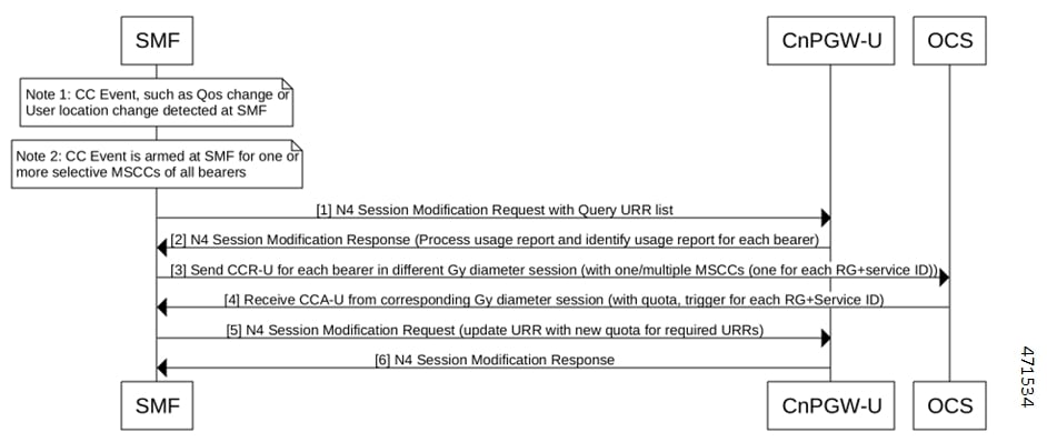
Figure 5. Usage Report in N4 Modify Response (Query URR Scenario)
Table 17. Usage Report in N4 Modify Response (Query URR Scenario) Call Flow Description

Step

Description

1

The SMF detects a Charging condition event and is armed for one or more specific MSCCs of all the bearers. Then, SMF creates a list of Query URR for the bearers that are armed. After the creation of this list, the SMF sends the N4 Session Modification Request with the Query URR list to the CnPGW-U.

2

The CnPGW-U sends the N4 Session Modification Response to SMF with the usage report. SMF processes and identifies the usage report for each bearer.

3

The SMF sends the CCR-U message for each bearer in different Gy Diameter sessions to OCS. These sessions can have one or multiple MSCCs, which is one for each Rating Group and service ID.

4

The OCS sends the CCA-U message from the corresponding Gy Diameter session to SMF. The Diameter session includes details, such as quota and triggers for each Rating Group and Service ID.

5

The SMF sends the N4 Session Modification Request to CnPGW-U. This request includes details on the required URRs with quota.

6

The CnPGW-U sends the N4 Session Modification Response to SMF.

N4 Session Report

This section provides details on the N4 Session Report.

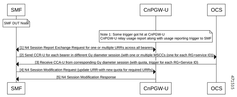
Figure 6. N4 Session Report
Table 18. N4 Session Report Call Flow Description

Step

Description

1

A Device Under Test (DUT) node exists on SMF.

Note


The CnPGW-U contains various URRs with values, such as threshold, quota, and triggers. Some triggers hit at CnPGW-U for a specific URR. The CnPGW-U sends the usage report along with usage reporting trigger to SMF.

CnPGw-U sends the N4 Session Report to SMF for one or multiple URRs across bearers.

2

The SMF sends the CCR-U message for each bearer in different Gy Diameter sessions to OCS. These sessions can have one or multiple MSCCs, which is one for each Rating Group and service ID.

3

The OCS sends the CCA-U message from the corresponding Gy Diameter session to SMF. The Diameter session includes details, such as quota and triggers for each Rating Group and Service ID.

4

The SMF sends the N4 Session Modification Request to CnPGW-U. This request includes details on the required URRs with new quota.

5

The CnPGW-U sends the N4 Session Modification Response to SMF.

Usage Report in N4 Modify Response (Remove URR Scenario)

This section provides details on the usage report in the N4 Modify Response for the remove URR scenario.

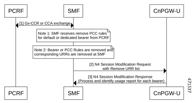
Figure 7. Usage Report in N4 Modify Response (Remove URR Scenario)
Table 19. Usage Report in N4 Modify Response (Remove URR Scenario) Call Flow Description

Step

Description

1

Both the PCRF and SMF exchange the Gx CCR and CCA messages.

Note

 
  • The SMF receives the N4 Session Modification Request with Remove URR list from PCRF.

  • The SMF removes the Bearer or PCC Rules and the corresponding URRs.

2

The SMF sends the N4 Session Modification Request with Remove URR list to CnPGW-U.

3

The CnPGW-U sends the N4 Session Modification Response to SMF. SMF processes and identifies the usage report for each bearer.

4

If the SMF removes one or multiple PCC Rules from a bearer, the SMF sends the CCA-U or Credit Control Answer - Terminate (CCR-T) message for each bearer in different Gy Diameter sessions to OCS. These sessions can have one or multiple MSCCs with Used Service Unit (USU).

5

The OCS sends the CCA-U or CCA-T message from the corresponding Gy Diameter session without quota to SMF.

Usage Report in N4 Delete Session Response

This section provides information on the usage report in N4 Delete Session Response.

Figure 8. Usage Report in N4 Delete Session
Table 20. Usage Report in N4 Delete Session Call Flow Description

Step

Description

1

Note


The SMF detects the UE or Network-initiated Delete session.

The SMF sends the N4 Delete Session Request to to CnPGW-U to delete the session. The CnPGW-U sends the usage report in the N4 Delete Session Response to SMF.

2

The SMF sends the CCR-T message for each bearer in different Gy Diameter sessions to OCS. These sessions can have one or multiple MSCCs with USU.

3

The OCS sends the CCA-T message from the corresponding Gy Diameter session to SMF.

Gy Failure Handling

Feature Description

A Diameter Failure Handling Template is associated to different Diameter services. A Diameter endpoint pod receives a command-level failure for a Gy message from OCS. Then, the Diameter endpoint pod handles the failure handling configuration.

Supported Actions and Sub-actions

The following table lists the supported failure handling template actions and sub-actions for the Gy interface:

Table 21. Supported Failure Handling Template Actions and Sub-actions

Action

Sub-action

Continue

  • FHSubActionEnum_UNKNOWN

  • FHSubActionEnum_DISCARD_TRAFFIC

Terminate

  • FHSubActionEnum_WITH_TERM_REQUEST

  • FHSubActionEnum_WITHOUT_TERM_REQUEST

Use Cases
Charging Behavior for Failure Handling Template Actions

Following table lists the charging behavior for failure handling template actions:

Table 22. Charging Behavior for Failure Handling Template Actions
Procedure

Failure Handling Template (Actions and Sub-actions)

SMF Behavior
CCR-I (PDN Setup) Continue + Unknown/None

Disable Charging

No URR created.

No Gy CCR-T is available during detach procedure.

No Gy CCR-U during any trigger or update.

Gy Offline charging “Enabled under “Charging-params” (Only for default bearer)

Continue + Discard

Drop Forwarding Action Rules (FAR)

Send URR with drop FAR ID.

No Gy CCR-T is available during detach procedure.

No Gy CCR-U during any trigger or update.

Gy Offline charging “Enabled under “Charging-params” (Only for default bearer)

Terminate + without term Terminate the session without Gy CCR-T message
Terminate + with term Terminate the session with Gy CCR-T message
CCR-I (Start of Traffic) Continue + Unknown/None

Known URR:

Allocate high quota

No Gy CCR-T during detach.

No Gy CCR-U during any trigger or update.

GyOffline charging “Enabled under “Charging-params” (Only for default bearer)

Unknown URR:

Disable OCS charging

No URR created.

No Gy CCR-T during detach.

No Gy CCR-U during any trigger or update.

GyOffline charging “Enabled under “Charging-params” (Only for default bearer)

Continue + Discard

Drop FAR

Send URR with drop FAR ID

No Gy CCR-T during detach.

No Gy CCR-U during any trigger or update.

GyOffline charging “Enabled under “Charging-params” (Only for default bearer)

Terminate + without term Terminate the session without Gy CCR-T message
Terminate + with term Terminate the session with Gy CCR-T message

MBR Procedure:

Scenario:

N4 Modification (Query URR)

Gy CCR-U (Usage)

Gy CCA-U (failure)

Continue + None

Allocate high quota

Sent CCR-T in dettach

Gy Offline charging "Enabled" in "Charging-params" (Only for default ebarer)

Continue + Discard

Drop FAR

Link created URR to Drop FAR.

Sent CCR-T in detach

GyOffline charging is "Enabled" in "Charging-params" (Only for default bearer)

Terminate + without term

If default bearer, then terminate the session without Gy CCR-T.

Terminate + with term

If default bearer, then terminate the session with Gy CCR-T.

Default Bearer Procedure (UBR):

Scenario:

UBR (QoS change)

N4 Modification

Gy CCR-U

Gy CCA-U fails

Continue + None

Allocate high quota

Sent CCR-T in detach

GyOffline charging “Enabled under “Charging-params” (Only for default bearer)

Continue + Discard

Drop FAR

Link created URR to drop FAR.

Sent CCR-T in detach

GyOffline charging “Enabled under “Charging-params” (Only for default bearer)

Terminate + without term

If default bearer, then terminate the session without Gy CCR-T.

Terminate + with term

If default bearer, then terminate the session with CCR-T.

Usage Report for Default bearer:

Scenario:

Session Report (for default bearer URR)

Gy CCR-U

Gy CCA-U (Fails)

Continue + None

Allocate high quota

Sent CCR-T in detach

Gy Offline charging “Enabled under “Charging-params” (Only for default bearer)

Continue + Discard

Drop FAR

Link created URR to drop FAR

Sent CCR-T in detach

GyOffline charging “Enabled under “Charging-params” (Only for default bearer)

Terminate + without term

If default bearer, then terminate the session without Gy CCR-T.

Terminate + with term

If default bearer, then terminate the session with Gy CCR-T.

BGIPC Failure

The Gy interface considers the BGIPC time-out and failure handling template. This behavior applies to the Gx interface too.

Charging Behavior for Non-Gy Failures

Following table lists the charging behavior for non-Gy failures:

Table 23. Charging Behavior for Non-Gy Failures
Step Procedure Failure Action
1 PDN Setup N4 failure Only if a CCR-I message is sent, Gy sends the CCR-T message.
2 PDN Modify (MBR)
2.1

Flow:

  • N4 Modification Request (Query URR)

N4 Modification Response (Usage):

  • Gy CCR-U (usage and trigger)

  • Gy CCA-U (quota)

N4 Modification (quota)

  • Gx CCR-U

First N4 (for query URR) fails No action is applicable to Gy
2.2 Second N4 after CCA-U (with quota) No action is applicable to Gy
3 Access Failure UBR
  • UBR—No action is applicable to Gy

Diameter Session Failover
Feature Description

This section describes about the SMF behaviour upon handling 4G session failure over Diameter interfaces.

How it Works

The following capabilities are added as part of this feature:

  • The SMF processes the CC-Session-Failover AVP received in the CCA-I and CCA-U from OCS.

  • The SMF overrides and stores the latest AVP information in the Diameter session on receiving the CC-Session-Failover AVP.

  • Based on the configuration and the CC-Session-Failover AVP information, the SMF service sends a session-failover flag indication in the next subsequent request of CCR-U or CCR-T to the Diameter endpoint.

  • If the session-failover CLI is enabled and OCS sends the CC-session-failover AVP, SMF retries the request to the secondary server if provisioned under the failure handling template.

  • The failover gets overridden by the server in the response message, and it takes precedence over the SMF service indication flag.

Configuring Session Failover

Use the following command to configure Session failover.

config 
   profile charging charging_profile_name 
      [ default | no ] session failover  
      exit 

NOTES:

  • profile charging charging_profile_name : Specify the charging profile name. charging_profile_name must be an alphanumeric string.

  • default session failover : Configures this command with default setting.


    Note


    Default setting depends on the failure-handling configuration.
  • no session failover : If the primary server isn’t reachable, failover isn’t triggered and the session is torn down. Failover action isn’t taken.

  • session failover : SMF retries the request to the secondary server if provisioned under the failure handling template.

Configuration Verification

Use the following command to verify if the Session failover handling profile is configured.


smf# show running-config profile charging chp
profile charging chp
  session failover
exit
Diameter Credit Control Failure Handling
Table 24. Feature History
Feature Name

Release Information

Description

Use of Credit-Control-Failure-Handling AVP for Gy request failure handling

2023.04

The SMF uses the value of Credit-Control-Failure-Handling AVP to derive the Gy request failure handling behavior when the requests are prevented due to a network problem.

Feature Description

As part of charging, the message exchange happens between the SMF service pod and the Diameter endpoint. To define the failure handling behaviour, the Online Charging Server (OCS) sends the Credit-Control-Failure-Handling Attribute Value Pair (AVP) to the Diameter endpoint. The Diameter endpoint forwards the received Gy Credit Control Answer - Initial (CCA-I) or Gy Credit Control Answer - Update (CCA-U) message along with the Credit-Control-Failure-Handling AVP. The SMF service pod stores this AVP from CCA-I or CCA-U OCS response messages and includes the Credit-Control-Failure-Handling AVP in the subsequent Credit Control Response - Update (CCR-U) messages. Then, the Diameter endpoint uses this AVP value to derive the Gy failure handling behavior when no is response received from the OCS or the command level failure result codes are received.

The SMF overrides the existing AVP value and stores the latest value in the charging subscriber data per Diameter session. The SMF service includes the stored value of the Credit-Control-Failure-Handling AVP in the subsequent Credit Control Request Update message. After receiving this message, the Diameter endpoint extracts the value of this AVP and sends it to OCS.


Note


The Diameter Credit Control Failure Handling takes precedence over the Diameter session failover and applies the action and subaction based on the received value of the Credit-Control-Failure-Handling AVP.


How it Works

The Diameter endpoint sends the following values of the Credit-Control-Failure-Handling AVP in the CCR-U message to SMF:

  • Terminate—Diameter endpoint sends the action as terminate and the subaction as without-termination to the SMF service pod.

  • Continue—Diameter endpoint sends the action as continue and the subaction as none to the SMF service pod.

  • Retry-AND-Terminate—Diameter endpoint sends the action as retry until it receives a successful message or until the retry count gets exhausted. After the retry count exhaustion, the Diameter endpoint sends the action as terminate and the subaction as without-termination to the SMF service pod.


    Note


    The Retry count value is derived from the failure handling template.


The following table is an example that lists the Credit-Control-Failure-Handling AVP value that OCS sends to the SMF service. The SMF service stores the received value for the subsequent CCR-U message.

Table 25. Credit-Control-Failure-Handling AVP Values from OCS to SMF
OCS AVP Value in Previous CCA-I or CCA-U Messages Smf-service Indication to Diameter Endpoint in CCR-U Message

1

CreditControl

FailureHandling AVP (Terminate)

CreditControl

FailureHandling AVP (Terminate)

2

CreditControl

FailureHandling AVP (Continue)

CreditControl

FailureHandling AVP (Continue)

3

CreditControl

FailureHandling AVP

(Retry-AND-Terminate)

CreditControl

FailureHandling AVP (Retry-AND

-Terminate)

Gy MSCC Level Failure Result Codes

Feature Description

This section describes about the SMF behaviour upon receiving “failure result codes received at MSCC level” for Transient Failures (4xxx) and Permanent Failures (5xxx) result codes.

Table 26. Transient Failures (4xxx)

Result Code

Description

4010

DIAMETER_END_USER_SERVICE_DENIED

4011

DIAMETER_CREDIT_CONTROL_NOT_APPLICABLE

4012

DIAMETER_CREDIT_LIMIT_REACHED

Table 27. Permanent Failures (5xxx)

Result Code

Description

5003

DIAMETER_AUTHORIZATION_REJECTED

5012

DIAMETER_UNABLE_TO_COMPLY

5030

DIAMETER_USER_UNKNOWN

5031

DIAMETER_RATING_FAILED

How it Works

The following table explains about the various SMF transient and permanent failure result codes:

Failure Codes

Description

SMF receives all the permanent failure result codes and transient failure result codes 4010 and 4012 in CCAI.

SMF sends zero time and volume quota in PFCP_SESSION_ESTABLISHMENT_REQUEST

SMF receives all the permanent failure result codes and transient failure result codes 4010 and 4012 in CCAU

SMF sends zero time and volume quota in PFCP_SESSION_MODIFICATION_REQUEST

SMF receives transient failure result code as 4011 in CCAI

SMF sends high (MAX) time and volume quota in PFCP_SESSION_ESTABLISHMENT_REQUEST

SMF receives transient failure result code as 4011 in CCAU

SMF sends high (MAX) time and volume quota in PFCP_SESSION_ESTABLISHMENT_REQUEST

SMF receives transient failure result code as 4011 in CCAU

SMF high (MAX) time and volume quota in PFCP_SESSION_MODIFICATION_REQUEST

SMF receives usage report with “termr” trigger in PFCP_SESSION_DELETION_RESPONSE message then

  • SMF sends CCRT message with 3GPP-reporting reason as “FINAL” for the URRs which has received MSCC failure code as 4010 and 4012

  • SMF sends CCRT message without MSCC for the URRs which has received MSCC failure code as 4011

  • SMF sends CCRT message with USU(time(0) + volume(0)) and 3GPP-reporting reason as “FINAL” for the URRs which has received all the permanent failure result codes

SMF receives all the permanent failure result codes and transient failure result codes 4010 and 4012 in CCAI:

  • SMF sends zero time and volume quota in PFCP_SESSION_ESTABLISHMENT_REQUEST: SMF receives all the permanent failure result codes and transient failure result codes 4010 and 4012 in CCAU.

  • SMF sends zero time and volume quota in PFCP_SESSION_MODIFICATION_REQUEST: SMF receives transient failure result code as 4011 in CCAI.

  • SMF sends high (MAX) time and volume quota in PFCP_SESSION_ESTABLISHMENT_REQUEST: SMF receives transient failure result code as 4011 in CCAU.

Architecture

This section describes about capturing the details related to processing of Multiple-Services-Credit-Control (MSCC) failure result codes at MSCC level in the Credit Control Application (CCA) messages received from Gy interface. This feature enables the SMF to process the Transient Failures (4xxx) and Permanent Failures(5xxx) at MSCC level from Gy interface in CCAI and CCAU messages.

Result Codes

The following table includes the various result codes and behaviour for Transient Failures (4xxx) and Permanent Failures (5xxx) result codes:

Table 28. Result Codes

Result Code

Behaviour

4010/4012 (CCAI)

  1. CCAI received with 4010/4012

  2. PFCP_SESSION_ESTABLISHMENT_REQUEST goes with CREATE FAR with APPLY ACTION as DROP:1, CREATE URR with REPORTING_TRIGGERS as "volqu, timqu" and VOLUME_QUOTA as 'volume_quota' : {'dlvol': 1, 'ulvol': 1, 'tovol': 1, 'total_vol': 0, 'up_vol': 0, 'down_vol': 0}, TIME_QUOTA as 'tm_quta' : 0

4010/4012 (CCAU)

  1. CCAU received with 4010/4012

  2. PFCP_SESSION_MODIFICATION_REQUEST goes with UPDATE FAR with APPLY ACTION as DROP:1, UPDATE URR with REPORTING_TRIGGERS as "volqu, timqu" and VOLUME_QUOTA as 'volume_quota' : {'dlvol': 1, 'ulvol': 1, 'tovol': 1, 'total_vol': 0, 'up_vol': 0, 'down_vol': 0}, TIME_QUOTA as 'tm_quta' : 0

4010/4012 (CCRT)

  1. PFCP_SESSION_DELETION_REQUEST received with usage report with timqu trigger

  2. CCRT should go with3GPP-Reporting reason as “FINAL”

4011 (CCAI)

  1. CCAI received with 4011

  2. PFCP_SESSION_ESTABLISHMENT_REQUEST goes with CREATE FAR APPLY ACTION as DROP:1, CREATE URR with REPORTING_TRIGGERS as "volqu, timqu" and VOLUME_QUOTA as 'volume_quota' : {'dlvol': 1, 'ulvol': 1, 'tovol': 1, 'total_vol': 9223372036854775807, 'up_vol': 9223372036854775807, 'down_vol': 9223372036854775807}, TIME_QUOTA as 'tm_quta' : 2147483647, TIME_THRESHOLD as 'time_treshold' : 10

4011 (CCAU)

  1. CCAU received with 4011

  2. PFCP_SESSION_MODIFICATION_REQUEST should go with UPDATE FAR APPLY ACTION as DROP:1, UPDATE URR with REPORTING_TRIGGERS as "volqu, timqu" and VOLUME_QUOTA as 'volume_quota' : {'dlvol': 1, 'ulvol': 1, 'tovol': 1, 'total_vol': 9223372036854775807, 'up_vol': 9223372036854775807, 'down_vol': 9223372036854775807}, TIME_QUOTA as 'tm_quta' : 2147483647, TIME_THRESHOLD as 'time_treshold' : 10

4011 (CCRT)

  1. PFCP_SESSION_DELETION_REQUEST received with usage report with timqu trigger

  2. CCRT goes without MSCC

5003/5012/5030/5031

(CCAI)
  1. CCAI received with 5003/5012/5030/5031

  2. PFCP_SESSION_ESTABLISHMENT_REQUEST goes with CREATE FAR with APPLY ACTION as DROP:1, CREATE URR with REPORTING_TRIGGERS as "volqu, timqu" and VOLUME_QUOTA as 'volume_quota' : {'dlvol': 1, 'ulvol': 1, 'tovol': 1, 'total_vol': 0, 'up_vol': 0, 'down_vol': 0}, TIME_QUOTA as 'tm_quta' : 0

5003/5012/5030/5031

(CCAU)
  1. CCAU received with 5003/5012/5030/5031

  2. PFCP_SESSION_MODIFICATION_REQUEST goes with UPDATE FAR with APPLY ACTION as DROP:1, UPDATE URR with REPORTING_TRIGGERS as "volqu, timqu" and VOLUME_QUOTA as 'volume_quota' : {'dlvol': 1, 'ulvol': 1, 'tovol': 1, 'total_vol': 0, 'up_vol': 0, 'down_vol': 0}, TIME_QUOTA as 'tm_quta' : 0

5003/5012/5030/5031

(CCRT)
  1. PFCP_SESSION_DELETION_REQUEST received with usage report with timqu trigger

  2. CCRT goes with USU(time(0)+volume(0)) and 3GPP-Reporting-Reason as “FINAL”


Note


Once SMF receives any supported failure codes for the URRS. No operations are performed on the URRs based on local trigger configuration or triggers received from OCS.


Gy Quota Validity Time (QVT) and Quota Holding Time (QHT)

Feature Description

The following capabilities are added to the SMF as a part of this feature:

  • The SMF is capable to receive Quota Validity time from Gy interface in CCAI and CCAU messages. After processing, SMF sends this information towards UPF in the following messages PFCP_SESSION_ESTABLISHMENT_REQUEST and PFCP_SESSION_MODIFICATION_REQUEST with trigger as “timqu”.

    If PFCP_SESSION_REPORT_REQUEST message receives usage report with “timqu” trigger, The SMF sends CCRU message with USU with time quota information and adds TGPPReportingReason as “VALIDITY_TIME”.

  • The SMF is capable to receive Quota Holding time from Gy interface in CCAI and CCAU messages. After processing SMF sends this information towads UPF in the following messages PFCP_SESSION_ESTABLISHMENT_REQUEST and PFCP_SESSION_MODIFICATION_REQUEST with trigger as “quhti”.

    PFCP_SESSION_ESTABLISHMENT_REQUEST PFCP_SESSION_MODIFICATION_REQUEST

    If PFCP_SESSION_REPORT_REQUEST message receives usage report with “quhti” trigger. The SMF sends CCRU message with USU with time quota information and adds TGPPReportingReason as “QHT”.

Quota-Validity-Time

This is an optional AVP and may only occur in a CCA command. It is contained in the Multiple-Services-Credit-Control AVP. This field defines the time in order to limit the validity of the granted quota for a given category instance.

The following requirements are supported by SMF:

  • Validity-Time” received in Gy CCAI/CCAU messages establishment or modification

  • The SMF process received validity time, if it is eligible to send the information towards UPF

    SMF Sends validity time as “tm_quta” in PFCP_IE_TIME_QUOTA and set the trigger as timqu with in PFCP_IE_REPORTING_TRIGGERS in: PFCP_SESSION_ESTABLISHMENT_REQUEST and PFCP_SESSION_MODIFICATION_REQUEST

  • SMF can receive PFCP_IE_USAGE_REPORT_REP_REQ with timqu as trigger and duration in “durton_msrt” in PFCP_SESSION_REPORT_REQUEST message

  • SMF process usage report sends received “durton_msrt” as “CC-Time” inside Used-Service-Unit and 3GPP-Reporting-Reason added as VALIDITY_TIME with in Multiple-Services-Credit-Control AVP in CCRU.

  • If SMF received “volume_msrmt” along with “durton_msrt”, then “CC-Total-Octets“, “CC-Input-Octets“, “CC-Output-Octets“ filled along with “CC-Time” inside Used-Service-Unit and 3GPP-Reporting-Reason added as VALIDITY_TIME with in Multiple-Services-Credit-Control AVP in CCRU.

  • If cnPGW not “Validity-Time” receives in Gy CCAI/CCAU messages then it read from charging profile configuration and apply it.

Quota-Holding-Time

This is an optional AVP and may only occur in a CCA command. It is contained in the Multiple-Services-Credit-Control AVP. It applies equally to the granted time quota and to the granted volume quota.

The following requirements are supported by the SMF:

  • 3GPP-Quota-Holding-Time” received in Gy CCAI/CCAU messages establishment or modification

  • SMF Sends holding time as “quta_hldg_tm” in PFCP_IE_QUOTA_HOLDING_TIME and set the trigger as quhti with in PFCP_IE_REPORTING_TRIGGERS in PFCP_SESSION_ESTABLISHMENT_REQUEST and PFCP_SESSION_MODIFICATION_REQUEST

  • SMF can receive PFCP_IE_USAGE_REPORT_REP_REQ with quhti as trigger

  • SMF process usage report 3GPP-Reporting-Reason added as QHT with in Multiple-Services-Credit-Control AVP in CCRU.

Volume-Quota-Threshold

This is an optional AVP and may only occur in a CCA command. It is contained in the Multiple-Services-Credit-Control AVP. If cnPGW and not the “3GPP-Volume-Quota-Threshold” is received in the Gy CCAI/CCAU messages, then it reads the information from the charging profile configuration and applies it.

How it Works

The SMF sends the quota validity time towards the N4 in “tm_quta” in PFCP_IE_TIME_QUOTA IE. If SMF receives only Quota validity time from CCAI/CCAU or both cc-Time and validity-time are received and validity time is less. If both values are equal then SMF sends cc-Time value in tm_quta. The SMF does not forward the 3GPP-Time-Quota-Threshold to N4, if quota validity time is selected.

If received quota holding time is valid, the SMF sends the quota holding time towards the N4.


Note


  • Zero Validity Time:

    In SMF validity time or holding time values are forwarded to N4, if validity time or holding time values received from CCRI/CCRU are 0. The SMF relays 0 because honouring 0 is mechanism to disable armed timer at UPF. QVT and QHT implementation is aligned with SMF if validity time or holding time values are received from CCRI/CCRU are 0.

  • QHT trigger received:

    In SMF, volume_msrmt, duration_msrmt are recived along with quhti trigger, CCRU sends volume_msrmt, duration_msrmt inside USU and updates reporting reason as QHT in MSCC level and also sends “Requested-Service-Unit”. QHT implementation is aligned with SMF if volume_msrmt, duration_msrmt are recived along with quhti trigger.


Logging

Following debug logs are present in various scenarios if validity time is received from the Gy interface:

  • Only validity-Time received:

    Validity Time present, not time quota

  • Validity-Time and cc-Time received:

    Time Quota is smaller than validity Time

    Time Quota is Greater than validity Time

    Time Quota is equal to validity Time

Gy Tarrif Time Support

Feature Description

The Tarrif switch time functionality applies when a subscriber switches form one tarrif plan to another. The Tariff-Time-Change AVP is used to determine the tariff switch time, and the Monitoring-Time IE is used to support the Tarrif Time support functionality.

After a tariff timer expiry, the gateway accumulates the usage separately in a charging bucket and continues to consume from the original quota value. At the time of next reporting, (Quota exhausted or another control events) the gateway reports both usages (before and after tarrif time change) for the same charging bucket.

How it Works

The SMF processes the Tariff-Time-Change AVP in Granted-Service-Unit (GSU) level from Gy interface in CCAI and CCAU messages. The SMF includes the Tariff-Change-Usage AVP inside Used-Service-Unit (USU) in CCRU and CCRT messages when the usage report is received from UPF.

Following scenarios are supported:

  • Tariff-Time-Change with Quota-Holding-Time Expired Trigger

  • Tariff-Time-Change with Validity-Time Expired Trigger

  • Tariff-Time-Change with Volume/Time-Quota Exhausted Trigger

  • Tariff-Time-Change with Volume/Time-Quota-Threshold Trigger

  • Tariff-Time-Change with Immediate Reporting Trigger

  • Tariff-Time-Change with Terminate Reporting Trigger

The following capabilities are added to the SMF as part of this feature:

  • The OCS provides "Tariff-Time-Change" AVP in CCAI/CCAU messages. After processing, SMF sends this information towards the UPF in PFCP Session Establishment Request and PFCP Session Modification Request using PFCP_IE_MONITORING_TIME IE.

  • The SMF receives two usage reports for each URR:

    • one with “Usage Report Trigger” as 'MONIT' and “ PFCP_IE_USAGE_INFORMATION” as ‘bef’ with "PFCP_IE_VOLUME_MEASUREMENT" and "PFCP_IE_DURATION_MEASUREMENT".

    • other usage report with “Usage Report Trigger” as 'TIMQU' and “ PFCP_IE_USAGE_INFORMATION” as ‘aft’ with "PFCP_IE_VOLUME_MEASUREMENT" and "PFCP_IE_DURATION_MEASUREMENT".

  • The SMF uses different USU to forward both the usage reports within MSCC towards OCS in CCRU/CCRT messages.

    .

    • first usage report, one with "MONIT" trigger is forwarded in USU1 with "Tariff-Change-Usage: UNIT_BEFORE_TARIFF_CHANGE" and

    • second usage report, one with "TIMQU" tigger is forwarded in USU2 with "Tariff-Change-Usage: UNIT_AFTER_TARIFF_CHANGE ".

Origin Host and Origin Realm for Gy

For each subscriber, SMF maintains a record of the Origin-Realm and Origin-Host attribute information sent by OCS through Diameter messages. If there’s any value change to the Origin-Host and Origin-Realm attributes, SMF updates the latest value and interacts with the corresponding destination host. Later, SMF increments the ocs_dest_host_change_stats statistics for every change in the attribute value.

Pending Traffic Treatment over Diameter Interfaces

The SMF implements the 3GPP recommendations for interworking of Evolved Packet System (EPS) and Diameter Interfaces such as Gy for Online Charging System (OCS) for prepaid subscribers, where it supports pending traffic management during the quota refresh procedure.

Pending Traffic Treatment (PTT) allows pass or drop treatment of traffic that flows at the User Plane Function (UPF) while waiting for Quota Information from P-GW. The traffic is treated based on the following supported configurations under the credit-control group in the Active Charging Service in UPF:

  • pending-traffic-treatment noquota pass

  • pending-traffic-treatment noquota drop

  • pending-traffic-treatment noquota limited-pass volume < in bytes, ranging from 1 to 4294967295>

  • pending-traffic-treatment quota-exhausted pass

  • pending-traffic-treatment quota-exhausted drop


Note


To enable pending traffic treatment over diameter interfaces no configuration is required under the SMF.

For more information, see the Sample UPF Configuration chapter in the UCC 5G UPF Configuration and Administration Guide and the Credit Control Configuration Mode Commands chapter in the Command Line Interface Reference, Modes C - D.

Routing Data Support

Feature Description

The Routing Data support functionality allows the SMF to:

  • Process routing data received in CCA-I/CCA-U from OCS

  • Override and store the routing data information in the ChargingSubData per diameter session. Smf-service includes stored routing data values in the next subsequent CCR-U or CCR-T message. The smf always expects routing data in CCA-I/CCA-U from OCS.

Monitoring and Troubleshooting

This section provides information for troubleshooting any issues that might arise during the feature operation.

The following is an example output of Routing data per Gy diameter session for a subscriber,

"gyDiamSession": {
                            "brrId": 1,
                            "sessionID": ":2:69:ocs-prof:64c37b62:1",
                            "originHost": "dummyOriginHost",
                            "originRealm": "dummyOriginRealm.com",
                            "destRealm": "dummyGyDestRealm.com",
                            "destHost": "Gy-server",
                            "RoutingData": {
                                "primaryHost": "10.105.34.14",
                                "primaryRealm": "dummyGyDestRealm.com",
                                "boundPeer": "Gy-server"
                            }
                        },

Gz Interface

Table 29. Feature History

Feature Name

Release Information

Description

Asynchronous and Synchronous Usage Report for Offline Bearer Recalculation

2023.04

As part of Gz Usage Reporting, SMF receives Asynchronous and Synchronous Usage Reporting for Offline Bearer recalculation.

Handling Modify Bearer Request Triggers

2023.04

SMF receives the Modify Bearer Request from S-GW for the User Location and TimeZone changes, change notifications. SMF supports N4 Query Interface and Recalculate Interface IEs for Rulebase change, Secondary RAT Usage limit, and Record closing triggers.

Default Setting: Disabled – Configuration required to enable

Gz Default Bearer Modification

2023.04

This feature allows PCRF-initiated modification of a default Bearer through Gx CCR-U and Gx RAR. You can perform the following functions:

  • Add rules to the Default Bearer

  • Delete rules from the Default Bearer

  • Rulebase Modification

  • Default-bearer QoS change

  • APN-AMBR change

PDN Attach and Detach with Gz Interface

Feature Description

The SMF with Legacy Interface supports the Packet Data Network (PDN) attach with Gz interface for a default Bearer to enable offline accounting functions.

How It Works

On receiving offline rules from the PCRF through Gx CCA-I, SMF with the Diameter interface creates offline URRs, maps to the corresponding charging buckets (SDFs), and sends N4EstablishmentRequest toward SMF with the Legacy Interface.

On receiving the Usage report for offline SDF/Bearer level URRs, in the N4 Delete Session Response from UPF, it sends the GTPP Data Record Transfer request toward GTPP. For more information about the Gz Usage Report, see the Subscriber Charging > Gz Usage Report Handling with GTPP section.

Use the PDN attach and detach with Gz inteface functionality to:

  • Attach Procedure with:

    • offline rules only (Gx+Gz)

    • offline and online rules (Gx+Gy+Gz)

  • Detach Procedure with:

    • offline rules only (Gx+Gz)

    • offline and online rules (Gx+Gy+Gz)

Information Element and AVP Support

The PDN attach and detach feature supports the following Information Element(IE):

  • Reporting Level IE for offline rules: ReportingLevel for dynamic rules is received from PCRF in Gx CCA-I. The other conditions are:

    • If ReportingLevel is not present for dynamic offline rule, then SMF considers reporting level based on the RG and service ID received:

      • if only RG received then reporting level is RatingGroupLevel

      • if both RG and ServiceID received then reporting level is ServiceIdentifierLevel

    • If ReportingLevel is present for dynamic offline rule, then the same is considered.


    Note


    The default offlineReportingLevel configuration is not applicable for Gz.
Handling Offline AVP for Dynamic Rules

The following table describes the function of offline AVPs for Dynamic rules.

Table 30. Rule Level and Command Level AVPs
AVP

Description

Offline AVP in Gx CCR-I

The offline AVP present in Gx CCR-I indicates default configuration for offline charging method. If Gz is enabled, then offline AVP is set to enabled in Gx CCR-I. If not, it is set to disabled.

Offline AVP in Gx CCA -I/ CCA-U/ RAR

If Offline AVP at RULE level is present within charging rule definition, it defines offline charging method for the corresponding dynamic rule. If enabled, offline charging is done for corresponding dynamic rule. If disabled, offline charging is not done for the corresponding dynamic rule.

If offline AVP at RULE level is absent within charging rule definition, offline AVP at COMMAND level is considered to determine if offline charging method for dynamic rule is enabled or disabled

If Offline AVP is absent at RULE and COMMAND levels, the default offline charging method is applied for the dynamic rule. If Gz is enabled, the default offline charging method for dynamic rules is enabled. If not, default offline charging method is disabled.

Handling Offline Dynamic Rules when Gz is Disabled

If Gz is disabled in rulebase, no SDF and bearer level URR are created for offline dynamic rule.The table lists possible combination of input values.

Table 31. Combination of Input Values
Gz enabled in Rulebase profile

Dynamic rule

has offline enabled

Offline URR

created in N4

TRUE

TRUE

TRUE

TRUE

FALSE

FALSE

FALSE

TRUE

FALSE

FALSE

FALSE

FALSE

Abnormal GTPP Record Closure

If there are any path failure either from the Control Plane or User Plane, GTPP record closure with abnormal release message is sent for any one of the following reason:

  • UPF session report ERIR

  • UPF session report SRIR

  • GTPU peer path failure

  • UPF recovery release

  • UPF path peer failure

  • Gtpc peer path fail release

  • Gtpc peer restart release

PDN Attach with only Offline Rules

The following call flow and procedure describes PDN attach when dynamic rule with offline is enabled through Gx and Gz interfaces.

Figure 9. Call Flow for PDN Attach with Only Offline Rules
Table 32. Call Flow Description for PDN Attach
Step Description
1

SMF sends Gx CCR-I towards PCRF.

2

PCRF sends Gx CCA-I towards SMF with default bearer having Dynamic rule with OFFLINE_ENABLED set to True.

3

The N4 Establishment Request is sent towards UPF based on the following conditions:

  • CREATE_URR for default bearer level URR, if:

    • PFCP_IE_URR_ID is set to 0x80000002 for default bearer level URR

    • PFCP_IE_VOLUME_THRESHOLD and PFCP_IE_TIME_THRESHOLD has egcdr threshold values configured in rulebase profile.

    • PFCP_IE_MEASUREMENT_METHOD has both volume and duration bit set.

  • CREATE_URR for offline SDF level URR, if:

    • PFCP_IE_URR_ID has unique offline UrrId

    • PFCP_IE_VOLUME_THRESHOLD and PFCP_IE_TIME_THRESHOLD has egcdr threshold values configured in the GTPP profile.

    • PFCP_IE_MEASUREMENT_METHOD has both volume and duration bit set.

    • All SDF level offline URRs are linked to bearer level URR. That is, PFCP_IE_LINKED_URR_ID has linked URRId set to the BearerLevel URR.

  • PDR created for dynamic offline rule is mapped to both bearer and SDF level URR.

4

UPF sends N4Establishment response.

PDN Attach with Offline and Online Rules

The following call flow and procedure describes PDN attach when dynamic rule with both online and offline is enabled through Gx, Gy, and Gz interfaces.

Figure 10. Call Flow
Table 33. Call Flow Description for PDN Attach with Offline and Online Rules
Step Description
1

SMF sends Gx CCR-I towards PCRF.

2

PCRF sends Gx CCA-I towards SMF with default bearer having Dynamic rule with OFFLINE_ENABLED set to True.

3

The N4 Establishment Request is sent towards UPF based on the following conditions:

  • CREATE_URR for default bearer level URR, if:

    • PFCP_IE_URR_ID is set to 0x80000002 for default bearer level URR

  • CREATE_URR for offline SDF level URR, if:

    • PFCP_IE_VOLUME_THRESHOLD and PFCP_IE_TIME_THRESHOLD has egcdr threshold values configured in the GTPP profile.

  • CREATE_URR for Online URR, if:

    • PFCP_IE_URR_ID has unique online UrrId

    • PFCP_IE_VOLUME_THRESHOLD and PFCP_IE_TIME_THRESHOLD has threshold values received from OCS

    • PFCP_IE_MEASUREMENT_METHOD is set based on quota received from OCS.

  • PDR created for dynamic rule (online+offline) is mapped to online, offline SDF and bearer level URR.

4

UPF sends N4Establishment response.

PDN Detach with Offline and Online rules

The following call flow and procedure describes the Usage report in Session Deletion Response.

Figure 11. Call Flow for Usage report as part of N4 Session Delete Response
Table 34. Call Flow Description for N4 Session Deletion Response
Step Description

UE/Network Initiated delete session is detected at SMF.

1

N4 Delete Session Request or Response is exchanged to delete the session and in turn Usage report is received in the N4 Delete session Response.

3

SMF sends GTPP Data Transfer Request with or without SDF Containers.

  • If the offline Usage report is received in the N4 Session Deletion Response, then SMF sends the GTPP Data Record Transfer Request for default with SDFs container(with volume usage and serviceConditionChange—one for each RG+service ID.

  • If the offline Usage report is received without measurement in the N4 Session Deletion Response and no offline Volume/Time threshold usage report received before detach, then the GTPP Data Record Transfer message with GTPP server.

  • If any offline Volume/Time threshold Usage report is received before detach and no offline Usage report in the N4 Delete Session Response received, then the GTPP Data Record Transfer gets exchanged without SDF Containers for record closure.

4

SMF receives GTPP Data Record Transfer Response from the GTPP server.

Enabling Gz Interface

Use the configuration commands to enable the Gz interface. When the offline AVP is absent at rule and command level, default offline charging method is applied for the dynamic rule. If the Gz interface is enabled, the default offline charging method for dynamic rules is enabled, else the default offline charging is disabled.

config 
   active-charging service service_name 
      rulebase rulebase_name 
         billing-records egcdr value  
   profile gtpp-profile   profile_name  gtpp dictionary dictionary_num 
   profile network-element ofcs  ofcs_name  gtpp-profile profile_name  
   profile dnn intershat network-element-profiles ofcs ofcs_name | 
end  

NOTES:

  • rulebase rulebase_name : Specify the name of the ACS rulebase. rulebase_name must be an alphanumeric string of 1 to 63 characters.


    Note


    A rulebase is a collection of protocol rules to match a flow and associated actions to be taken for matching flow.
  • billing-records egcdr value : Specify to enable eG-CDR billing to True. This associates CnPGW-C with Gz interface in the corresponding rulebase profile. Further, if PCRF sends a different rulebase in Gx CCA-I, Gz interface gets enabled or disabled as per billingRecord EGCDR configuration received in the new rulebase.

  • profile gtpp-profile profile_name gtpp dictionary dictionary_num : Configure the gtpp profile with dictionary. The correct dictionary is gtpp dictionary custom24. profile_name specifies list of associated GTPP Profile names that are used in a round robin method for sessions. The maximum number of gtpp profiles allowed is 4.

  • profile network-element ofcs ofcs_name gtpp-profile profile_name : Configure the network profile ofcs. The OFCS profile config allows option to configure multiple gtpp profiles.


    Note


    Before configuring the network profile ofcs ensure to configure the gtpp-profile.
Configuring Bearer Level URR Threshold Values

Use the configuration commands to set the Bearer level threshold values.

config 
   active-charging service service_name 
      rulebase rulebase_name 
         egcdr threshold volume { downlink | total | uplink }  bytes  
end  

NOTES:

  • rulebase rulebase_name : Specify the name of the ACS rulebase. rulebase_name must be an alphanumeric string of 1 to 63 characters.

  • egcdr threshold volume { downlink | total | uplink } bytes : Specify the Bearer level URR threshold values. The limit for the number of downlink, total , or uplink octets must be an integer in the range of 100000-4000000000. Example: egcdr threshold volume downlink 100000 uplink 100000 total 200000

Configuring SDF Level Offline URR Threshold Values

Use the configuration commands to set the Service Data Fow (SDF) level threshold values.

config 
    active-charging service service_name 
       charging-action charging_action 
          egcdr service-data-flow threshold volume { downlink | total | uplink } bytes  
          egcdr service-data-flow threshold interval interval   60
    end 

NOTES:

  • charging-action charging_action_name : Specify the name of a charging action. charging_action_name must be an alphanumeric string of 1 to 63 characters and can contain punctuation characters. Each charging action must have a unique name.

  • egcdr service-data-flow threshold volume { downlink | total | uplink } bytes : Specify the SDF level offline URR threshold values. The limit for the number of downlink, total , or uplink octets must be an integer in the range of 100000-4000000000.

  • egcdr service-data-flow threshold interval interval : Configure the threshold for offline charging. Must be an integer in the range of 60–40000000.

Configuring max-losdv Values

Use the configuration commands to create GTPP Data Record with number of Service Data Flow (SDF) container equivalent to the configured maxlosdv value. If the maxlosdv is not configured the default value is 1.

config 
    active-charging service service_name 
       charging-action charging_action 
          egcdr losdv-max-containers container_num  
    end 

NOTES:

  • charging-action charging_action_name : Specify the name of a charging action. charging_action_name must be an alphanumeric string of 1 to 63 characters and can contain punctuation characters. Each charging action must have a unique name.

  • egcdr losdv-max-containers container_num : Specify the maximum List of Service Data containers (LOSDV) for creating a GTPP data record.

Configuring closure-reason

Use the following command to configure closure reason to send in a GTPP Data Record. The closure reason can be for mgmt-intervention or normal release. Default closure reason is mgmt-intervention.

config 
    active-charging service service_name 
       charging-action charging_action 
          egcdr closure-reason { admin-disconnect | normal-release |  }     
    end 

NOTES:

  • charging-action charging_action_name : Specify the name of a charging action. charging_action_name must be an alphanumeric string of 1 to 63 characters and can contain punctuation characters. Each charging action must have a unique name.

  • egcdr closure-reason { admin-disconnect | normal-release | } : Configure the closure reason.

Gz Usage Reporting

Feature Description

At the time of a converged User Plane function, the P-GW (User Plane) sends the Usage report for triggers such as Volume or Time threshold value for offline charging. During the converged Control Plane function, the P-GW (Control Plane) queries a Usage report when the Charging condition event is detected or URR is removed as part of the Policy Control and Charging (PCC) rule removal at SMF.

After receiving the Usage report, the Control Plane maps URRs to the corresponding offline charging parameter. If the offline charging parameter is not available, then a Service Data Flow (SDF) or Bearer level charging parameter is created for static or predefined rules, and the GTPP Data Record Transfer request is initiated for the respective SDFs. Thus, a Synchronous usage report is received through the N4 Modification Response or N4 Deletion Response message. Asynchronous usage report is received through the N4 Session report request message.

For more information, refer to the UCC 5G SMF Configuration and Administration Guide > Interfaces Support chapter.

How it Works

The usage report on the Gz interface includes the following usage report procedures

  • Offline Bearer or Offline Bearer along with SDF level, or SDF level URR for Dynamic rules

  • Offline Bearer or Offline Bearer along with SDF level, or SDF level URR for Static/Predefined rules

  • Online or offline URRs

  • N4 Delete Session Response.

Usage Report in N4 Session Report

The following call flows and procedures describe the Usage report in N4 session report with Volume or Time threshold.

Offline Bearer and SDF Level or SDF Level URR for Dynamic Rules

The following call flow and procedure describes the Usage report in N4 session report with Volume/Time threshold for the offline Bearer or SDF level, or SDF level URR for Dynamic rules.


Note


Ensure that the URR is present on the UPF with values such as Thresholds and so on. Volume/Time threshold is hit at the UPF for Bearer/SDF or SDF level URRs. UPF relays usage to the SMF along with usage reporting trigger information.
Figure 12. Call Flow for Offline Usage Report in N4 Session Report
Table 35. Call Flow Description for Offline Usage Report in N4 Session Report
Step Description
1

UPF sends N4 Session Report Request for either offline Bearer usage along with SDFs or only SDFs usage to the SMF.

2

SMF sends N4 Session Report Response.

3

SMF sends GTPP Data Record Transfer Request with SDF Containers to the Offline Charging System (OFCS). This request is sent with one or multiple SDFs with volume usage and serviceConditionChange—one for each RG+service ID.

Note

 
The algorithm works based one of the following conditions:
  • If the Offline Bearer Usage report is received along with the SDF or SDF Usage report that is received and max charging condition hit (max-losdv CLI configured value – default value is 1)

  • If an Offline Usage report received is without measurement for a Bearer level Time threshold in the N4 Session Report Request, then GTPP Data Record Transfer message with recordClosureReason “TimeLimit” without SDF Containers gets exchanged with OFCS.

  • If an Offline Usage report that is received is without measurement for the SDF level Time threshold in the N4 Session Report Request, then the GTPP Data Record Transfer message does not get exchanged with OFCS.

4

OFCS sends GTPP Data Record Transfer Response.

Sample Configuration

The following is sample message output for Dynamic Rule SDF level URR

URR ID: 
                Type: 81   Length: 4
                Value: 0x000000021. 
            USAGE REPORT TRIGGER: 
                Type: 63   Length: 2
                Time Threshold 
            VOLUME MEASUREMENT: 
                Type: 66   Length: 25
                Total Volume: 450
                Uplink Volume: 250
                Downlink Volume: 200
            DURATION MEASUREMENT: 
                Type: 67   Length: 4
                Value: 100   
             
        accessPointNameNi                    cisco.com 
        ratingGroup                          10
        chargingRuleBaseName                 cisco
        resultCode                           2001
        localSequenceNumber                  1
        timeOfFirstUsage                     220829173906-0400
        timeOfLastUsage                      220829173907-0400
        timeUsage                            1
        serviceConditionChange               Time Exhaust
         qCI                                  5
         maxRequestedBandwithUL               0
         maxRequestedBandwithDL               0
         guaranteedBitrateUL                  0
         guaranteedBitrateDL                  0
         aRP                                  5
        servingNodeAddress                   2002::2:61
        datavolumeFBCUplink                  250
        datavolumeFBCDownlink                200
        timeOfReport                         220829173907-0400
        userLocationInformation              
         Location Type                    TAI
          MCC                                214
          MNC                                365
          TAC                                0x6789
          Location Type                    ECGI
          MCC                                214
          MNC                                365
          ECI                                0x1234567
Offline Static or Predefined Rules

The following call flow and procedure describes the Usage report in N4 session report with Volume/Time threshold for the offline Bearer or SDF level, or SDF level URR for Predefined and Static Rules.

Figure 13. Call Flow for Usage Report in N4 Session Report for Offline Static or Predefined Rules
Table 36. Call Flow Description for Offline Static or Predefined Rules
Step Description
1

PCRF performs Gx-CCR or CCA exchange with SMF. In this exchange, the SMF receives Predefined Rules for default bearer from the PCRF.

2

SMF initiates N4 session establishment request exchange with UPF. In the same request, UPF relays the PFCP message exchange.as response.

3

SMF sends Create session request to the S-GW and GTPP response message is exchanged.

Note

 
Volume/Time threshold is detected at UPF and UPF prepares Usage report with VOLTH/TIMTH for the offline Bearer/SDF level or SDF level URR.

4

SMF sends N4 Session Report Request/Response exchange with offline Volume/Time threshold.

When SMF receives the SDF level or Bearer/SDF level usage report with VOLTH/TIMTH for static/predefined rules, the Bearer/SDF level URR is created at SMF if not there, and the SDF level URR gets linked to the Bearer level URR.

5

SMF sends GTPP Data Record Transfer Request with SDF Containers to the Offline Charging Server (OFCS). This request is sent with one or multiple SDFs with volume usage and serviceConditionChange—one for each RG+service ID.

Note

 
The algorithm works based one of the following conditions:
  • If the offline Bearer Usage report is received along with the SDF or SDF Usage report received and a maximum charging condition is hit (max-losdv CLI configured value – default value is 1).

  • If the offline Usage report received is without measurement for the Bearer level Time threshold in the N4 Session Report Request, then the GTPP Data Record Transfer message with recordClosureReason “TimeLimit” without SDF Containers gets exchanged with OFCS.

  • If the offline usage report received is without measurement for the SDF level Time threshold in the N4 Session Report Request, then the GTPP Data Record Transfer message does not get exchanged with OFCS.

6

OFCS sends GTPP Data Record transfer response to the SMF.

Sample Configuration

The following is a sample message output for offline SDF level URR Id for static rule Usage report:

URR ID:
                Type: 81   Length: 4
                Value: 0x80000021.  
            USAGE REPORT TRIGGER: 
                Type: 63  
                Vol Threshold
            VOLUME MEASUREMENT: 
                Type: 66  
                Total Volume: 400
                Uplink Volume: 200
                Downlink Volume: 200

                
        accessPointNameNi                    cisco.com  
        ratingGroup                          101
        chargingRuleBaseName                 prepaid
        resultCode                           2001
        localSequenceNumber                  1
        timeOfFirstUsage                     220920093554-0400
        timeOfLastUsage                      220920093558-0400
        timeUsage                            4
        serviceConditionChange               Volume Exhaust
         qCI                                  5
         maxRequestedBandwithUL               512000
         maxRequestedBandwithDL               512000
         guaranteedBitrateUL                  0
         guaranteedBitrateDL                  0
         aRP                                  84
        servingNodeAddress                   192.60.7.31
        datavolumeFBCUplink                  200
        datavolumeFBCDownlink                200
        timeOfReport                         220920093601-0400
        userLocationInformation              
         Location Type                    CGI
          MCC                                404
          MNC                                43
          LAC                                0x84C
          CI                                 0x4F0A 
Online and Offline URRs

The following call flow and procedure describes the Usage report in N4 session report for online and offline URRs.

Figure 14. Call Flow for Usage Report in N4 Session Report for Online and Offline
Table 37. Call Flow Description for Online and Offline URRs
Step Description
1

PCRF performs Gx-CCR or CCA Exchange with SMF. In this Exchange, the SMF receives Dynamic Rules for default bearer from the PCRF.

2

SMF initiates N4 session establishment request Exchange with UPF. In the same request, UPF relays the PFCP message Exchange as response.

3

SMF sends Create session request to the S-GW and the GTPP response message is exchanged.

Note

 
Volume/Time threshold that is detected at the UPF and UPF prepares a usage report with VOLTH/TIMTH for the online URR and offline Bearer/SDF level or SDF level URR.

4

SMF sends N4 Session Report Request/Response Exchange with online and offline Volume/Time threshold.

When SMF receives the SDF level or Bearer/SDF level usage report with VOLTH/TIMTH for online URR and offline bearer/SDF level URR.

5

SMF sends GTPP Data Record Transfer Request with SDF Containers to the Offline Charging Server (OFCS). This request is sent with one or multiple SDFs with volume usage and serviceConditionChange—one for each RG+service ID.

Note

 
The algorithm works based one of the following conditions:
  • If the Offline Bearer Usage report is received along with the SDF or SDF Usage report received and a maximum charging condition is hit (max-losdv CLI configured value – default value is 1).

  • If the offline Usage report received is without measurement for the Bearer level Time threshold in the N4 Session Report Request, then the GTPP Data Record Transfer message with recordClosureReason “TimeLimit” without SDF Containers gets exchanged with OFCS.

  • If the offline Usage report received is without measurement for the SDF level Time threshold in the N4 Session Report Request, then the GTPP Data Record Transfer message does not get exchanged with OFCS.

6

OFCS sends GTPP Data Record transfer response to the SMF.

7

SMF sends Gy CCR-U with one or multiple MSCCs—for each RG+SID.

8

SMF receives Gy CCA-I with quota, triggers for each RG+Service ID.

9

SMF sends N4 Session Modification Request to the UPF with update-URR. The Quota is received from OCS for the required online URRs.

10

UPF sends N4 Session Modification Response.

Sample Configuration

The following is a sample message output for offline Bearer level URR.

URR ID: 
                Type: 81   Length: 4
                Value: 0x80000002   --- Offline Bearer level URR Id
            USAGE REPORT TRIGGER: 
                Type: 63   Length: 2
                Volume Threshold 
            VOLUME MEASUREMENT: 
                Type: 66   Length: 25
                Total Volume: 101096
                Uplink Volume: 896
                Downlink Volume: 100200
            DURATION MEASUREMENT: 
                Type: 67   Length: 4
                Value: 16
            
            URR ID: 
                Type: 81   Length: 4
                Value: 0x80000021. 
            USAGE REPORT TRIGGER: 
                Type: 63   Length: 2
                Linked Usage Reporting 
            VOLUME MEASUREMENT: 
                Type: 66   Length: 25
                Total Volume: 101096
                Uplink Volume: 896
                Downlink Volume: 100200
       DURATION MEASUREMENT: 
                Type: 67   Length: 4
                Value: 1  

                     
        accessPointNameNi                    cisco.com
        ratingGroup                          10
        chargingRuleBaseName                 cisco
        resultCode                           2001
        localSequenceNumber                  1
        timeOfFirstUsage                     220829173906-0400
        timeOfLastUsage                      220829173907-0400
        timeUsage                            1
        serviceConditionChange               Volume Limit
         qCI                                  5
         maxRequestedBandwithUL               0
         maxRequestedBandwithDL               0
         guaranteedBitrateUL                  0
         guaranteedBitrateDL                  0
         aRP                                  5
        servingNodeAddress                   2002::2:61
        datavolumeFBCUplink                  896
        datavolumeFBCDownlink                100200
        timeOfReport                         220829173907-0400
        userLocationInformation              
         Location Type                    TAI
          MCC                                214
          MNC                                365
          TAC                                0x6789
          Location Type                    ECGI
          MCC                                214
          MNC                                365
          ECI                                0x1234567
Offline Usage Report in N4 Session Deletion Response

The following call flow and procedure describes the Usage report in Session Deletion Response.


Note


Ensure that the UE or Network Initiated delete session is detected at the SMF.
Figure 15. Call Flow for Usage Report in N4 Delete Session Response
Table 38. Call Flow Description for Session Deletion Response
Step Description
1

SMF initiates N4 Session Deletion Request to delete the session to the UPF.

2

UPF sends N4 Session Deletion Response with offline Usage report.

3

SMF sends GTPP Data Transfer Request with or without SDF Containers.

  • If the offline Usage report is received in the N4 Session Deletion Response, then SMF sends the GTPP Data Record Transfer Request for default with SDFs container(with volume usage and serviceConditionChange—one for each RG+service ID.

  • If the offline Usage report is received without measurement in the N4 Session Deletion Response and no offline Volume/Time threshold usage report received before detach, then the GTPP Data Record Transfer message with recordClosureReason “NormalRelease” without SDF Containers gets exchanged with OFCS.

  • If any offline Volume/Time threshold Usage report is received before detach and no offline Usage report in the N4 Delete Session Response received, then the GTPP Data Record Transfer gets exchanged without SDF Containers for record closure.

4

SMF receives GTPP Data Record Transfer Response from OFCS.

Offline SDF Usage Report in N4 Session Report

The Offline SDF or Bearer URRs are present on UPF with values like Thresholds and so on. SDF Volume/Time threshold is hit at the UPF for SDF level URRs. UPF relays usage to the SMF along with usage reporting trigger information. The following call flow and procedure describes the Asynchronous Usage report for offline Bearer recalculation.

Figure 16. Call Flow for Asynchronous Usage report for offline Bearer recalculatio
Table 39. Call Flow Description for Async Usage Report Offline Bearer Recalculation
Step Description
1

UPF initiates N4 Session Report Exchange with SMF.

2

SMF sends GTPP Data Transfer Request with SDF Containers.

  • If the Offline usage report is received in the N4 Session Report Request, then the SMF sends a GTPP Data Record Transfer Request with SDFs container with volume usage and serviceConditionChange—one for each RG+service ID only if the maximum charging condition is reached.

  • If the Offline usage report that is received is without measurement for SDF level time threshold in the N4 Session Report Request, then a GTPP Data Record Transfer message does not get exchanged with OFCS.

3

SMF receives GTPP Data Record Transfer Response from OFCS.

4

After receiving the Offline SDF usage, if the SMF sends GTPP Data Record Transfer Request due to maximum charging condition, then N4 Modification Request with Update Bearer level URR (Bearer Recalculate) is sent to the UPF.

5

UPF sends N4 Modification Response.

Offline SDF or Online URRs Usage Report

For the Volume/Time threshold detected at UPF, the UPF prepares the Usage report with VOLTH/TIMTH for online URR or offline SDF level URR. The following call flow and procedure describes the Asynchronous Usage report for online or offline Bearer Recalculation.

Figure 17. Call Flow for Async Usage Report Online or Offline Bearer Recalculate
Table 40. Call Flow Description for Async Usage Report Online or Offline Bearer Recalculation
Step Description
1

UPF initiates N4 Session Report Request/Response exchange with online/offline Volume/Time threshold.

2

SMF sends GTPP Data Transfer Request with SDF Containers.

  • If the Offline usage report is received in N4 Session Report Request, then SMF sends the GTPP Data Record Transfer Request with SDFs container(with volume usage and serviceConditionChange—one for each RG+service ID only if the maximum charging condition is hit.

  • If the Offline usage report received is without measurement for the SDF level time threshold in the N4 Session Report Request, then the GTPP Data Record Transfer message does not get exchanged with OFCS.

3

SMF receives GTPP Data Record Transfer Response from OFCS.

4

SMF sends Gy CCR-U with one or multiple MSCCs (for each RG+Service ID) to the OCS.

5

SMF receives Gy CCA-I with quota, triggers for each RG+Service ID.

6

SMF sends N4 Session Modification Request to the UPF.

Note

 
The update URR-with quota for required online URRs and update URR – with bearer recalculate for offline bearer level URR is sent.

7

UPF sends N4 Session Modification Response to the SMF.

Offline Bearer Usage Report

The Offline SDF or Bearer URRs are present on UPF with values like Thresholds and so on. SDF Volume/Time threshold is hit at the UPF for Bearer URRs. UPF relays usage to the SMF along with usage reporting trigger information. The following call flow and procedure describes the Offline Bearer Usage Report in N4 session report with no Bearer Recalculation.

Figure 18. Async Offline Bearer Usage Report
Table 41. Call Flow Description for Async Offline Bearer Usage Report with no Bearer Recalculation
Step Description
1

UPF sends N4 Session report Request with offline Bearer along with SDF usage to the SMF.

2

SMF sends N4 Session report Response to the UPF.

3

SMF sends GTPP Data Transfer Request with SDF Containers with volume usage and serviceConditionChange—one for each RG+service ID only if the maximum charging condition is hit.

If the offline usage report received is without measurement for the Bearer level time threshold in the N4 Session Report Request, then the GTPP Data Record Transfer message is sent without the SDF container with OFCS.

4

SMF receives the GTPP Data Record Transfer Response from OFCS.

Note

 
When the Bearer usage report is received without volume measurement, the SMF does not send a bearer recalculation to the UPF.
Offline SDF Usage Report

The following call flow and procedure describes the Offline Bearer Usage Report in N4 session report with no Bearer Recalculation.

Figure 19. Call Flow for Async Usage Report Offline with no Bearer Recalculate
Table 42. Call Flow Description for Async Offline Bearer Usage Report witn no Bearer Recalculation
Step Description

Note

 
Offline SDF/Bearer URRs are present on UPF with values such as Thresholds and so on. SDF Volume or Time threshold is hit at UPF for SDF level URRs. UPF need to relay usage to SMF along with Usage reporting trigger information.

1

UPF send N4 Session report Request with offline SDF usage to SMF.

2

SMF sends N4 Session report Response to UPF.

Note

 
When the SDF usage report is received and maximum charging condition is not hit, SMF does send CDR to OFCS and Bearer recalculate to UPF.

The max-losdv CLI value configured as 2 and only one SDF usage report is received. Once the second SDF level usage is received and the maximum charging condition is hit then, CDR is sent to the GTPP and Bearer recalculate to UPF.

Synchronous Online and Offline Usage Report for Offline Bearer Recalculation

The following call flow and procedure explains the Offline SDFs and Online URRs Usage Report in N4 Session Modification Request with immediate trigger.

Figure 20. Call Flow for Sync Usage Report
Table 43. Call Flow Description for Synchronous Online and Offline Usage Report for Offline Bearer Recalculation
Step Description

Note

 
The Default Bearer is created with one dynamic online and offline rule. The ULI trigger is locally configured under charging profile for OFCS and OCS. Modify Bearer Request with ULI change is received.

1

S-GW sends Modify Bearer Request with new ULI.

2

SMF sends Modify Bearer Response to the S-GW.

3

SMF sends N4 Session Modification request to the UPF with query URR for online and Query Interface for offline URRs.

SMF sends N4 Session Modification request to the UPF with query URR for online URRs and Query Interface and Recalculate Interface with offline bit set to 1 for offline URRs.

4

UPF sends N4 Session Modification Response for Offline SDFs and Online URRs with reporting trigger Immediate.

5

SMF sends GTPP Data Transfer Request with SDF Containers.

  • If the Offline usage report is received in the N4 Session Modification Response, then SMF sends the GTPP Data Record Transfer Request with SDFs container with volume usage and serviceConditionChange—one for each RG+service ID only if the maximum charging condition is hit.

  • If the Offline usage report received is without measurement for the SDF level time threshold in the N4 Session Modification Response, then the GTPP Data Record Transfer message does not get exchanged with OFCS.

6

SMF receives GTPP Data Record Transfer Response from OFCS.

7

SMF sends Gy CCR-U with one/multiple MSCCs for each RG+SID to the OCS.

8

SMF receives Gy CCA-I with quota, triggers for each RG+Service ID.

9

SMF sends N4 Session Modification Request with update URR-with received quota for online URRs and update URR – with bearer recalculate for offline bearer level URR.

10

UPF sends N4 Session Modification Response to the SMF.

Sample Configuration

The following is a sample message output for an Offline Bearer level URR.

URR ID: 
                Type: 81   Length: 4
                Value: 0x80000002   
            USAGE REPORT TRIGGER: 
                Type: 63   Length: 2
                Time Threshold 
            VOLUME MEASUREMENT: 
                Type: 66   Length: 25
                Total Volume: 450
                Uplink Volume: 250
                Downlink Volume: 200
            DURATION MEASUREMENT: 
                Type: 67   Length: 4
                Value: 100
            
            URR ID: 
                Type: 81   Length: 4
                Value: 0x00000021.  
            USAGE REPORT TRIGGER: 
                Type: 63   Length: 2
                Linked Usage Reporting 
            VOLUME MEASUREMENT: 
                Type: 66   Length: 25
                Total Volume: 450
                Uplink Volume: 250
                Downlink Volume: 200
            DURATION MEASUREMENT: 
                Type: 67   Length: 4
                Value: 87
                
        accessPointNameNi                    cisco.com
        ratingGroup                          10
        chargingRuleBaseName                 cisco
        resultCode                           2001
        localSequenceNumber                  1
        timeOfFirstUsage                     220822005641-0400
        timeOfLastUsage                      220822005646-0400
        timeUsage                            5
        serviceConditionChange               Time Limit
         qCI                                  5
         maxRequestedBandwithUL               0
         maxRequestedBandwithDL               0
         guaranteedBitrateUL                  0
         guaranteedBitrateDL                  0
         aRP                                  5
        servingNodeAddress                   2002::2:61
        datavolumeFBCUplink                  250
        datavolumeFBCDownlink                200
        timeOfReport                         220822005818-0400
        userLocationInformation              
         Location Type                    TAI
          MCC                                214
          MNC                                365
          TAC                                0x6789
          Location Type                    ECGI
          MCC                                214
          MNC                                365
          ECI                                0x1234567
OAM Support

This section describes operations, administration, and maintenance information regarding support for interfaces in SMF.

Bulk Statistics Support

The following counters are added for the Gz charging functionality:

  • ofcs_cdr_message_stats— The counter is incremeted for every CDR towards CGF. The following labels are added:

    • gtpp_profile gtpp_profile_name : This metric displays the GTPP profile.

    • RuleBase RuleBase Name : This metric displays the rule base name.

    • record_closure_reasonrecord_closure_reason : This metric displays any one of the record closure reasons:

      • normalRelease

      • abnormalRelease

      • cAMELInitCallRelease

      • volumeLimit

      • timeLimit

      • servingNodeChange

      • maxChangeCond

      • managementIntervention

      • intraSGSNIntersystemChange

      • rATChange

      • mSTimeZoneChange

      • sGSNPLMNIDChange

      • dnn dnn_name : This metric displays the DNN name.

      • TriggerType Trigger_name : This metric displays the following GZ_SECONDARY_RAT_USAGE_LIMIT_REACHED trigger type.

  • ofcs_sdf_container_stats—The counter is incremeted for every SDF Containers of CDR towards CGF. The following labels are added.

  • service_condition_change service_condition_change_value : The service_condition_change label value is a comma separated in case of multiple service condition change values for each SDF container. This metric displays any one of the service condition change values:

    • QoSChange

    • PdpContextRelease

    • ConfigurationChange

    • ServiceStop

    • DccaTimeExhausted

    • DccaVolumeExhausted

  • ofcs_cdr_drop_stats —The counter is incremeted for every CDR is suppressed due to Zero suppression towards OFCS. The following labels are added:

    • procedure_type procedure_name : This metric displays SMF procedure name along with trigger name, which met the suppression criterion.

    • TriggerType Trigger_name : This metric displays any one of the following trigger names:

      • final-cdr

      • external-trigger-cdr

      • intrenal-trigger-cdr

    • dnn dnn_name : This metric displays the DNN name.

Handling Modify Bearer Request Triggers

Feature Description

SMF receives the Modify Bearer Request from S-GW for the User Location and TimeZone changes. The following functionalities are supported through triggers:

  • TimeZone Trigger: Use the CHANGE_IN_UE_TIMEZONE trigger to identify timezone change

  • ULI Triggers: Use the CHANGE_IN_LOCATION, CHANGEINLOCATION_TAC and CHANGEINLOCATION_ECGI to identify a location change.

Limitations

Following are the limitations:

  • SMF supports QueryInterface and RecalculateInterface for only Gz offline URRs. It is not supported for Gy online URR and RADIUS URR.

  • RecalculateInterface value (264) IE type is not in the vendor type range as specified by specification. Update to RecalculateInterface value (264) IE type is required when support is available at UPF.

  • Trigger Handling for Dedicated Bearer is not supported.

Timezone Change

Timezone information is sent only at CDR level. The following call flow depicts the Timezone change in the SMF.

Figure 21. Modify Bearer Request with Timezone Change
Table 44. Call Flow Description for Timezone Change

Step

Description

A Default Bearer is established successfully and an initial attach happens with dynamic, static, and predefined rules.

1

SMF receives Modify Bearer request from S-GW with Timezone change.

2

SMF sends the Modify Bearer response.

3

N4 modification request is sent with the following details:

  • QueryUrr for online URR

  • Query Interface with bearer_urr set for Bearer URR

  • Recalculate Interface with offline_urr and bearer_urr for SDF URR.

Note


When the bearer_urr is queried in the Query Interface, recalculate is requested for both bearer and offline/SDF URR in the Recalculate Interface.

4

SMF receives an N4 modification response from UPF with the following details:

  • UsageReport for Bearer URR and linked SDF URRs

  • UsageReport for online URR

5

SMF sends GTPP Data Record Transfer request to the GTPP with record closure reason Timezone change.

Note

 
A TimeZone change is a record closure event as per the specification. Hence, the Bearer URR is queried and a CDR is sent in the subsequently.

6

SMF receives the GTPP Data Record Transfer Response.

7

UPF sends a Gy CCR-U message with usage that is received to the OCS.

8

SMF receives Gy CCA-U from OCS.

Sample N4 Modification Request
PFCP_SESSION_MODIFICATION_REQUEST (52)
'Retransmit flag'  : 0
'Seid'             : 17293822569102704642
'Length'           : 71
'Sequence Number'  : 3
'Number of IEs'    : 5
    PFCP_IE_SUB_PARAMS (226)
      'sub_params' : {'rat_type': 6, 'sgsn_v4': '10.105.38.134', 'uli_len': 13, 'uli': {'spare': 0, 'ecgi': 1, 'tai': 1, 'nrtai': 0, 'nrcgi': 0, 'tai-mcc': 123, 'tai-mnc': 456, 'tai-tac': 2347, 'ecgi-mcc': 123, 'ecgi-mnc': 456, 'ecgi-spare': 0, 'ecgi-eci': 1234567}, 'ggsn_v4': '10.21.82.217'}

    PFCP_IE_QUERY_URR (77)

            PFCP_IE_URR_ID (81)
                  'urr_id' : 55

    PFCP_IE_PFCPSMREQFLAGS (49)
           'spare' : 0
           'qaurr' : 1
           'sndem' : 0
           'drobu' : 0

    PFCP_IE_QUERY_INTERFACE (253)
    'query_interface' : {'spare_3bit': 0, 'offline_urr': 0, 'online_urr': 0, 'radius_urr': 0, 'bearer_urr': 1, 'sess_urr': 0}

    PFCP_IE_RECALCULATE_INTERFACE (264)
    'recalculate_interface' : {'spare_3bit': 0, 'offline_urr': 1, 'online_urr': 0, 'radius_urr': 0, 'bearer_urr': 1, 'sess_urr': 0}


        MESSAGE BUFFER:
                2134 0047 F000 0000 0000 0002 0000 0304
                00E2 001C 0100 012A 060A 6926 860D 1821
                6354 092B 2163 5400 12D6 870A 1552 D904
                004D 0008 0051 0004 0000 0037 0031 0001
                0400 FD00 0110 0108 0001 10
TimeZone Information sent at CDR level

The following table describes timezone information sent at CDR level.

PreCondition Scenarios Expected Behaviour

Maxlosdv 1

CSR with MsTimeZone

Bearer threshold 60 seconds

TimeZone trigger enable

Attach with TimeZone1

Bearer usage received for Time threshold

MBR with TimeZone2

Bearer usage received for Time threshold

MBR with TimeZone3

Bearer usage received for Time threshold

Detach with traffic data

On the N4 interface, Query for TimeZone change happens with bearer bit set for offline.

After receiving first bearer usage, CDR is sent with TimeZone1

After receiving bearer usage for the first MBR, CDR is sent with TimeZone1

After receiving second bearer usage, CDR is sent with TimeZone2

After receiving bearer usage for second MBR, CDR is sent with TimeZone2

After receiving third bearer usage, CDR is sent with TimeZone3

For terminate usage report during detach, CDR is sent with TimeZone3

Maxlosdv 1

CSR without MsTimeZone

Bearer threshold 60 seconds

TimeZone trigger enable

Attach without TimeZone

Bearer usage received for Time threshold

MBR with TimeZone1

Bearer usage received for Time threshold

MBR with TimeZone2

Bearer usage received for Time threshold

Detach with traffic data

On the N4 interface, Query for TimeZone change happens with bearer bit set for offline.

After receiving the first Bearer usage, CDR is sent without TimeZone

After receiving the Bearer usage for first MBR, CDR is sent without TimeZone

After receiving second bearer usage, CDR is sent with TimeZone1

After receiving Bearer usage for second MBR, CDR is sent with TimeZone1

After receiving third Bearer usage, CDR is sent with TimeZone2

For terminate usage report during detach, CDR is sent with TimeZone2

Maxlosdv 1

CSR with MsTimeZone

Bearer threshold 60 seconds

Suppress zero cdrs

TimeZone trigger enable

Attach with TimeZone1

MBR with TimeZone2 and zero usage(no traffic, zero volume) received

MBR with TimeZone3 and zero usage(no traffic, zero volume) received

Zero usage(no traffic, zero volume) received for Time threshold for no traffic

Detach with traffic data

On the N4 interface, Query for TimeZone change happens with bearer bit set for offline.

For terminate usage report during detach, CDR is sent with TimeZone2

Maxlosdv 1

CSR with MsTimeZone

Bearer threshold 60 seconds

TimeZone trigger disable

Attach with TimeZone1

Bearer usage received for Time threshold

MBR with TimeZone2

Bearer usage received for Time threshold

MBR with TimeZone3

Bearer usage received for Time threshold

Detach

On N4 Query for TimeZone change does not happen for offline.

All CDRs are sent with TimeZone1

Maxlosdv 1

CSR without MsTimeZone

Bearer threshold 60 seconds

TimeZone trigger disable

Attach with TimeZone1

Bearer usage received for Time threshold

MBR with TimeZone2

Bearer usage received for Time threshold

MBR with TimeZone3

Bearer usage received for Time threshold

Detach

On N4 Query for TimeZone change shall not happen for offline.

All CDR shall be sent without TimeZone.

User Location Information Change

The User Location Information is sent at both CDR and SDFcontainer level. After the attach is performed, one CDR gets opened with the current record opening time and with current ULI. Once a CDR is generated another CDR is opened with the current record opening time and with the last user location information.

The following call flow depicts the User Location Information (ULI) change in the SMF.

Figure 22. Modify Bearer Request with ULI Change
Table 45. Call Flow Description for ULI Change

Step

Description

1

Default Bearer is established successfully and an initial attach happens with dynamic, static, and predefined rules.

2

SMF receives Modify Bearer request from S-GW with ECGI, which is modified in ULI.

3

SMF sends Modify Bearer Response.

4

N4 modification request is sent with the following details:

  • QueryUrr for online URR.

  • Query Interface with offline_urr set for SDF URR.

  • Recalculate Interface with offline_urr set for SDF URR.

Note


When the offline_urr is queried in the Query Interface, recalculation is requested for only offline/SDF URR in the Recalculate Interafce.

5

SMF receives N4 modification response from UPF with the following details:

  • UsageReport for SDF URRs

  • UsageReport for online URR

6

SMF sends GTPP Data Record Transfer request with record a closure reason as Max_change_condition and serviceConditionChange as ECGI change.

Note

 
ULI change is not a closure event record as per the specification. Hence, the SDF URR is queried. On receiving the Usage report for the same, if MaxLosDv is hit, CDR is sent with the corresponding reason.

6

SMF receives the GTPP Data Record Transfer Response.

7

UPF sends a Gy CCR-U message with usage that is received to the OCS.

8

SMF receives Gy CCA-U from OCS.

Sample N4 Modification Request
PFCP_SESSION_MODIFICATION_REQUEST (52)
'Retransmit flag'  : 0
'Seid'             : 17293822569102704642
'Length'           : 71
'Sequence Number'  : 3
'Number of IEs'    : 5
    PFCP_IE_SUB_PARAMS (226)
      'sub_params' : {'rat_type': 6, 'sgsn_v4': '10.105.38.134', 'uli_len': 13, 'uli': {'spare': 0, 'ecgi': 1, 'tai': 1, 'nrtai': 0, 'nrcgi': 0, 'tai-mcc': 123, 'tai-mnc': 456, 'tai-tac': 2347, 'ecgi-mcc': 123, 'ecgi-mnc': 456, 'ecgi-spare': 0, 'ecgi-eci': 1234567}, 'ggsn_v4': '10.21.82.217'}

    PFCP_IE_QUERY_URR (77)

            PFCP_IE_URR_ID (81)
                  'urr_id' : 55

    PFCP_IE_PFCPSMREQFLAGS (49)
           'spare' : 0
           'qaurr' : 1
           'sndem' : 0
           'drobu' : 0

    PFCP_IE_QUERY_INTERFACE (253)
    'query_interface' : {'spare_3bit': 0, 'offline_urr': 1, 'online_urr': 0, 'radius_urr': 0, 'bearer_urr': 0, 'sess_urr': 0}

    PFCP_IE_RECALCULATE_INTERFACE (264)
    'recalculate_interface' : {'spare_3bit': 0, 'offline_urr': 1, 'online_urr': 0, 'radius_urr': 0, 'bearer_urr': 0, 'sess_urr': 0}


        MESSAGE BUFFER:
                2134 0047 F000 0000 0000 0002 0000 0304
                00E2 001C 0100 012A 060A 6926 860D 1821
                6354 092B 2163 5400 12D6 870A 1552 D904
                004D 0008 0051 0004 0000 0037 0031 0001
                0400 FD00 0110 0108 0001 10
Service Condition Change Reasons

Following are the service condition change reasons for the ULI change.

  • If the TAI has changed in ULI, ServiceConditionChange reason in CDR is “TaiChange”

  • If ECGI has changed in ULI, ServiceConditionChange reason in CDR is “EcgiChange”

  • If both TAI and ECGI changes in ULI, the ServiceConditionChange reason in CDR is a generic “UserLocationChange”

ULI Information sent at CDR and SDF Container Levels

The following table describes scenarios and its behavior for ULI information sent at CDR and SDF container level.

PreCondition Scenarios Expected Behaviour

Maxlosdv 1

CSR with ULI

Bearer threshold 60 seconds

ULI Trigger enable

Attach with ULI1

Bearer usage received for Time threshold

MBR with ULI2

Bearer usage received for Time threshold

MBR with ULI3

Bearer usage received for Time threshold

Detach

On N4 Query for ULI Information change happens with offline bit set for offline.

After receiving first Bearer usage, CDR and SDF containers are sent with ULI1.

After receiving SDF usage for 1st MBR, CDR and SDF containers are sent with ULI1.

After receiving 2nd bearer usage, CDR with ULI1 and SDF containers with ULI2 are sent.

After receiving SDF usage for 2nd MBR, CDR and SDF containers are sent with ULI2.

After receiving 3rd bearer usage, CDR with ULI2 and SDF containers with ULI3 are sent.

For terminate usage report during detach, CDR and SDF Containers are sent with ULI3.

Maxlosdv 1

CSR without ULI

Bearer threshold 60 seconds

ULI Trigger enable

Attach without ULI

Bearer usage received for Time threshold

MBR with ULI1

Bearer usage received for Time threshold

MBR with ULI2

Bearer usage received for Time threshold

Detach

On N4 Query for ULI Info change happens with offline bit set for offline.

After receiving 1st Bearer usage, CDR and SDF containers are sent without ULI.

After receiving SDF usage for 1st MBR, CDR and SDF containers are sent without ULI

After receiving second Bearer usage, CDR without ULI and SDF containers with ULI1 are sent.

After receiving SDF usage for second MBR, CDR and SDF containers are sent with ULI1.

After receiving third Bearer usage, CDR with ULI1 and SDF containers with ULI2 are sent.

For terminate usage report during detach, CDR and SDF containers are sent with ULI2.

Maxlosdv 1

CSR with ULI

Bearer threshold 60 seconds

Suppress zero cdrs

ULI Trigger enable

Attach with ULI1

MBR with ULI2 and zero usage(no traffic, zero volume) received

MBR with ULI3 and zero usage(no traffic, zero volume) received

Zero usage(no traffic, zero volume) received for Time threshold

Detach with traffic data

On N4 Query for ULI Information change happens with offline bit set for offline.

For terminate usage report during detach, CDR with ULI1 and SDF containers with ULI3 are sent.

Maxlosdv 3

CSR with ULI

Bearer threshold 60 seconds

ULI Trigger enable

Attach with ULI1

MBR with ULI2 and SDF usage zero(no traffic, zero volume)

MBR with ULI3 and SDF usage zero(no traffic, zero volume)

MBR with ULI4 and received 2 SDF usages

MBR with ULI5 and received 3 SDF usages

Detach with 2 SDF usages

On N4 Query for ULI information change happens with offline bit set for offline.

After receiving SDF usages for 4th MBR, one CDR with ULI1 and 3 SDF containers(SDF1 with ULI3, SDF2 with ULI3 and SDF3 with ULI4) are sent

After receiving terminate usage, 2 CDRs with SDF containers are sent.

1st CDR with ULI4 and 3 SDF containers(SDF4 with ULI4, SDF5 with ULI4 and SDF6 with ULI5)

2nd CDR with ULI5 and one SDF containers(SDF7 with ULI5).

Maxlosdv 1

CSR with ULI

Bearer threshold 60 seconds

ULI Trigger disable

Attach with ULI1

Bearer usage received for Time threshold

MBR with ULI2

Bearer usage received for Time threshold

MBR with ULI3

Bearer usage received for Time threshold

Detach

On N4 Query for User Location information change does not happen for offline.

All CDR and SDF container are sent with ULI1

Maxlosdv 1

CSR without ULI

Bearer threshold 60 seconds

ULI Trigger disable

Attach without ULI

Bearer usage received for Time threshold

MBR with ULI1

Bearer usage received for Time threshold

MBR with ULI2

Bearer usage received for Time threshold

Detach

On N4 Query for User Location information change does not happen for offline.

All CDR and SDF container are sent without ULI.

Change Notification

The following call flow and procedure descibes Change Notification in the SMF.

Figure 23. Call Flow for Change Notification
Table 46. Call Flow Description for Change Notification Change

Step

Description

Note

 
Default Bearer is established successfully and an initial attach happens with dynamic, static,and predefined rules.

1

S-GW sends Change notification request to SMF. For example, the change notification is sent with ULI change-ECGI modified.

3

N4 modification request is sent with the following details:

  • QueryUrr for online URR

  • QueryInterface and RecalculateInterface for offline/SDF urr

5

SMF receives N4 modification response from UPF with the following details:

  • UsageReport for SDF URRs

  • UsageReport for offline and online URRs

6

SMF sends GTPP Data Record Transfer request to the GTPP with max-change_condition.

6

SMF receives the GTPP Data Record Transfer Response.

7

UPF sends Gy CCR-U message with usage received to the OCS .

8

SMF receives Gy CCA-U from OCS

Query Interface and Recalculate Interface IEs

The following table describes Query Interface and Recalculate Interface IEs.

Trigger N4 Query Interface N4 Recalculate Interface N4 Query URR
Rulebase Change

Query Interface with -bearer_urr': 1

"offline_urr": 0

“online_urr”:0

“radius_urr”:0

UPF will report Bearer level usage along with SDF level usage.

Recalculate Interface -"bearer_urr": 1

"offline_urr": 1

“online_urr”:0

“radius_urr”:0

NA
Secondary RAT Usage Limit

Query Interface with -bearer_urr': 1

"offline_urr": 0

“online_urr”:0

“radius_urr”:0

UPF will report Bearer level usage along with SDF level usage.

Recalculate Interface - "bearer_urr": 1

"offline_urr": 1

“online_urr”:0

“radius_urr”:0

Record Closing trigger- Example: time zone change

Query Interface with -bearer_urr': 1

"offline_urr": 0

“online_urr”:0

“radius_urr”:0

UPF will report Bearer level usage along with SDF level usage.

Recalculate Interface - "bearer_urr": 1

"offline_urr": 1

“online_urr”:0

“radius_urr”:0

online and radius
SDF Level Query - Ex: QOS Change

Query Interface with -bearer_urr': 0

"offline_urr": 1

“online_urr”:0

“radius_urr”:0

UPF will report all SDF level usage. SMF needs to send recalculate in same N4 to reset thresholds of SDF level URR

Recalculate Interface -

"bearer_urr": 0

"offline_urr": 1

“online_urr”:0

“radius_urr”:0

Online and radius
Recalculate Bearer Level Limits because of Record Closure - Max change condition NA

UPDATE URR:

Type: 13

Value:

URR ID:

Type: 81 Value: 0x80000002

RECALCULATE MEASUREMENT:

Type: 216

RCVOL: 1

RCDUR: 1

NA
Individual URR Query - Currently no use case in future will need this.

Query URR :

Value : <XYZ>

UPDATE URR:

Type: 13

Value:

URR ID:

Type: 81 Value: XYZ

RECALCULATE MEASUREMENT:

Type: 216

RCVOL: 1

RCDUR: 1

NA
Configuring Gz Triggers

To configure Gz triggers, use the following sample configuration.

config 
    active-charging service service_name 
       charging-action charging_action 
          egcdr  losdv-max-containers   service-data-flow triggers { ms-timezone-change [ true | false ] | qos-change [ true | false ] | uli-change [ true | false ] }  
    end 

NOTES:

  • egcdr losdv-max-containers : Configure maximum number of LoSDV containers in one EGCDR. The losdv-max-containers value must be an integer in the range of 1–255. By default the value is 1.

  • egcdr service-data-flow : Configure service data flows.

  • egcdr triggers { ms-timezone-change [ true | false ] | qos-change [ true | false ] | uli-change [ true | false ] }

    • egcdr triggers : Configure list of triggers for CDR. By default, the following triggers are enabled:

      • triggers ms-timezone-change [ true | false ] : Enable or disable MS Timezone trigger for CDR default.

      • triggers qos-change [ true | false ] : Enable or disable QoS change trigger for CDR default.

      • triggers uli-change [ true | false ] : Enable or disable User Location change trigger for CDR default.

Gz Default Bearer Modification

Feature Description

SMF supports PCRF-initiated modification of default bearer through Gx CCR-U and Gx RAR. You can perform the following functions:

  • Add rules to the Default Bearer

  • Delete rules from the Default Bearer

  • Rulebase Modification

  • Default-bearer QoS change

  • APN-AMBR change

How it Works

This section describes the call flows pertaining to the Gz Default Bearer Modification feature in SMF.

Call Flows
Adding Offline Rules to Default Bearer
Bearer level URR ID is created only once for each bearer. The following call flow and procedure describes various dynamic rule addition scenarios.
Figure 24. Call Flow for Adding Offline Rules to Default Bearer
Table 47. Call Flow Description for Adding Offline Rule to Default Bearer

Step

Description

Note

 
Ensure that the initial attach is successfully done with dynamic offline rule.

1

PCRF adds a new dynamic offline rule with different RG and service ID through Gx RAR.

2

SMF sends Gx RAA to PCRF.

3

SMF sends N4 Modification Request with CREATE_URR for offline SDF URR to UPF. The following conditions must be met:

  • PFCP_IE_URR_ID should have a unique offline URR ID

  • PFCP_IE_VOLUME_THRESHOLD and PFCP_IE_TIME_THRESHOLD should have eG-CDR threshold values that are configured in the GTPP profile.

  • PFCP_IE_MEASUREMENT_METHOD have both volume and duration bit set.

  • PFCP_IE_REPORTING_TRIGGERS have lisua bit set.

  • Linked to Bearer URR ID.

4

UPF sends N4 Modification response.

Adding First Dynamic Rule
Figure 25. Call Flow for First Dynamic Rule Addition
Table 48. Call Flow Description for Adding First Dynamic Rule

Step

Description

1

Ensure that the initial attach is successfully done with default bearer having single static offline rule.

2

PCRF adds first dynamic offline rule through Gx RAR.

3

SMF sends Gx RAA to PCRF.

3

SMF sends N4 Modification Request towards UPF:

  • CREATE_URR for default bearer level URR:

    • PFCP_IE_URR_ID is set to 0x80000002 for default bearer level URR.

    • PFCP_IE_VOLUME_THRESHOLD and PFCP_IE_TIME_THRESHOLD have eG-CDR threshold values that are configured in the Rulebase profile.

    • PFCP_IE_MEASUREMENT_METHOD has both volume and duration bit set.

  • CREATE_URR for offline SDF level URR:

    • PFCP_IE_URR_ID has a unique offline URR ID.

    • PFCP_IE_VOLUME_THRESHOLD and PFCP_IE_TIME_THRESHOLD have eG-CDR threshold values that are configured in the GTPP profile.

    • PFCP_IE_MEASUREMENT_METHOD has both volume and duration bit set.

    • PFCP_IE_REPORTING_TRIGGERS have lisua bit set.

    • Linked to Bearer URR ID.

4

UPF sends N4 Modification response.

Adding First Dynamic Rule after Usage Report
Figure 26. Call Flow for Adding First Dynamic Rule after Usage Report
Table 49. Call Flow Description for Adding First Dynamic Rule after Usage Report

Step

Description

Ensure that the initial attach is successfully done with the default bearer having a single static offline rule. Usage report is processed successfully for static offline rule.

2

PCRF adds the first dynamic offline rule through Gx RAR.

3

SMF sends Gx RAA to PCRF.

3

SMF sends N4 Modification Request toward UPF:

  • CREATE_URR for offline SDF level URR:

    • PFCP_IE_URR_ID has a unique offline URR ID.

    • PFCP_IE_VOLUME_THRESHOLD and PFCP_IE_TIME_THRESHOLD have eG-CDR threshold values that are configured in the GTPP profile.

    • PFCP_IE_MEASUREMENT_METHOD has both volume and duration bit set.

    • PFCP_IE_REPORTING_TRIGGERS have lisua bit set.

    • Linked to Bearer URR ID.

4

UPF sends N4 Modification response.

Deleting Rules from Default Bearer

The following call flow and procedure describes Rules deletion from the Default Bearer.

Figure 27. Call Flow for Deleting Rules from Default Bearer
Table 50. Call Flow Description for Deleting Rules from Default Bearer

Step

Description

1

Ensure that the initial attach is successfully done with dynamic offline rule.

2

PCRF removes dynamic offline rule through Gx RAR.

3

CnPGW-C sends Gx RAA to PCRF.

4

N4 Modification Request with REMOVE_URR for offline SDF URR is sent towards CnPGW-U.

5

CnPGW-U sends the following N4 Modification response:

  • PFCP_IE_USAGE_REPORT_MOD_RES received for removed URR

  • PFCP_IE_USAGE_REPORT_MOD_RES with ‘termr’ set

6

OFCS sends GTPP record transfer response. For example,
Maxlosdvcontainer: 1.GTPP Data Record Transfer Request is sent with 
single Service record for the removed URR
causeForRecClosing: Maximum change condition
serviceConditionChange:ServiceStop
QoS and APN-AMBR Change of Default Bearer

The following section describes QoS and APN-AMBR change for Default Bearers.

Figure 28. Call Flow for QoS/APN-AMBR with only Offline Rules Change
Table 51. Call Flow Description for QoS/APN-AMBR with only Offline Rules Change

Step

Description

1

Establish default dearer attach with dynamic, static, and predefined Offline rules. SMF must have CHANGE_IN_QOS, CHANGEINQOS_APN_AGGREGATE_MAXIMUM_BIT_RATE triggers configuration.

2

PCRF sends GxReAuthRequest with Apn-Ambr or QoS change. For example,change request can be sent for:

  • Default-Bearer QoS (QCI, ARP)

  • Apn-Ambr (Uplink or Downlink)

3

SMF sends GxReAuthAnswer to the PCRF.

4

SMF sends Update Bearer Request to the S-GW.

5

S-GW sends Update Bearer Response to the SMF.

6

UPF receives the following N4 Modification Request from SMF:

  • QueryInterface with offline_urr set for SDF URR

  • Re-calculate Interface with offline_urr set for SDF URR

7

SMF receives N4Modification response from UPF. For example, SMF receives UsageReport response for SDF URRs.

8

SMF sends GTPP Data Record Transfer request only if there are Maxlosdvcontainer configured limit hits.

9

SMF receives GTPP Data Record Transfer Response.

10

SMF sends N4 Modification Request with Recalculate_measurement for offline Bearer level URR to UPF.

11

UPF sends N4 Modification Response to SMF.

Figure 29. Call Flow for Offline and Online Rules Change
Table 52. Call Flow Description for QoS/APN-AMBR with Offline and Online Rules Change

Step

Description

1

Establish default bearer attach with the following dynamic, static, and predefined offline rules:

  • OCS arms Gy-triggers such as CHANGE_IN_QOS, CHANGEINQOS_APN_AGGREGATE_MAXIMUM_BIT_RATE for online rule.

  • SMF must have CHANGEINQOS_APN_AGGREGATE_MAXIMUM_BIT_RATE trigger configuration

2

PCRF sends GxReAuthRequest with APN-AMBR or QoS change. For example, change request can be sent for:

  • Default-Bearer QoS (QCI, ARP)

  • Apn-Ambr (Uplink or Downlink)

3

SMF sends GxReAuthAnswer to the PCRF.

4

SMF sends Update Bearer Request to the S-GW.

5

S-GW sends Update Bearer Response to the SMF.

6

UPF receives the following N4 Modification Request from SMF:

  • QueryInterface with offline_urr set for SDF URR

  • Re-calculate Interface with offline_urr set for SDF URR

7

SMF receives N4Modification response from UPF. For example, SMF receives UsageReport response for SDF URRs.

8

SMF sends GTPP Data Record Transfer request only if there are Maxlosdvcontainer configured limit hits.

9

SMF receives GTPP Data Record Transfer Response.

10

SMF sends Gy CCR-U to OCS with usage received from UPF in USU. For example,

QoS Change  => Reporting-Reason with RATING_CONDITION_CHANGE (6), Trigger - CHANGEINQOS_ANY (2).
Apn-Ambr Change => Reporting-Reason with RATING_CONDITION_CHANGE (6), Trigger - CHANGEINQOS_APN_AGGREGATE_MAXIMUM_BIT_RATE (24).

11

SMF receives Gy CCA-U received from OCS.

12

SMF sends N4 Modification Request with Recalculate_measurement for Offline Bearer level URR to UPF.

13

UPF sends N4 Modification Response to SMF.

QoS Sent in CDR

All the QoS information is sent only at SDF Container level. The APN-AMBR value is sent as zero in either maxRequestedBandwithUL or maxRequestedBandwithDL CDR SDF container.

PreCondition Scenarios Expected Behavior

Maxlosdv 1

Attach with Gx

SDF threshold 60 seconds

QoS trigger enable

Attach with Gx (QoS Info - QoS1)

SDF usage received for Time threshold

Gx RAR for QoS change - QoS2

SDF usage received for Time threshold

Gx RAR for QoS change - QoS3

SDF usage received for Time threshold

Detach

On N4 Query for QoS Information change happens with offline bit set for offline.

After receiving 1st SDF usage, CDR SDF containers is sent with QoS1

After receiving SDF usage for 1st RAR, CDR SDF containers is sent with QoS1

After receiving 2nd SDF usage, CDR SDF containers is sent with QoS2

After receiving SDF usage for 2nd RAR, CDR SDF containers is sent with QoS2

After receiving 3rd SDF usage, CDR SDF containers is sent with QoS3

For terminate usage report during detach, CDR SDF Containers is sent with QoS3

Maxlosdv 1

Attach without Gx

Bearer threshold 60 seconds

QoS trigger enable

Attach without Gx (default rule QoS)

SDF usage received for Time threshold

Bearer usage received for volume threshold

Detach

All CDR SDF container is sent with attach time default rule QoS information.

Maxlosdv 1

Attach with Gx

SDF threshold 60 seconds

QoS trigger disable

Attach with Gx (QoS Info - QoS1)

Bearer usage received for Time threshold

Gx RAR for QoS change - QoS2

Bearer usage received for Time threshold

Gx RAR for QoS change - QoS3

Bearer usage that is received for Time threshold

Detach

On N4 Query for QoS Information change does not happen for offline.

All CDR SDF containers are sent with attach time QoS info - QoS1

Maxlosdv 1

Attach without Gx

Bearer threshold 60 seconds

QoS trigger disable

Attach without Gx (default rule QoS)

SDF usage that is received for Time threshold

Bearer usage that is received for volume threshold

Detach

All CDR and SDF containers are sent with attach time default rule QoS information
Rulebase Modification

The following call flow and procedure describes Rule base modification.

Figure 30. Call Flow for Rulebase Modification
Table 53. Call Flow Description for Rulebase Modification

Step

Description

1

Ensure that the initial attach is successfully done with static, predefined, and dynamic rules.

2

S-GW modifies rulebase through Gx RAR to the SMF.

3

SMF sends Gx RAA to the S-GW.

4

SMF sends following N4 Modification Request towards UPF:

  • CREATE PDR for new rulebase

  • REMOVE PDR for old rulebase and predefined rule

  • QUERY INTERFACE with bearer_urr bit set

  • RECALCULATE INTERFACE with bearer_urr and offline_urr bit set

5

UPF sends the following N4 Modification response to the SMF:

  • PFCP_IE_USAGE_REPORT_MOD_RES for bearer level URR with ‘immer’ flag set

  • PFCP_IE_USAGE_REPORT_MOD_RES for all SDF offline URRs with ‘liusa’ flag set

6

SMF sends the GTPP Data Record Transfer Request to the SMF.

For example, GTPP Data Record Transfer Request is sent with
ForRecClosing: Management Intervention
serviceConditionChange:Configuration change

7

GTPP confirms that GTPP Data Record Transfer Response received to the SMF.


Note


When billing record is changed through rulebase modification, the Bearer URR is queried if atleast one of the offlline rule (dynamic, static, or activated predefined rule) is currently installed. For example,

  • If an attach is done with billing record disabled and no offline rules present. When billing record is modified to enabled through rulebase change, no Bearer URR is queried as no offline rules were present in the system.

  • If a new rulebase has EGCDR billing record disabled, exsisting dynamic offline rules are not removed and usage report for the same continues. However, when new offline rule is added, offline URR does not get created for the same and marked as validation failure because of billing record disable.


Handling Periodic Report of Secondary RAT Usage

Table 54. Feature History

Feature Name

Release Information

Description

Periodic Report of Secondary RAT Usage

2023.04

This feature allows SMF to handle periodic Secondary RAT data volume report messages from the MME over the S5 or S8 interface in the Modify Bearer Request, Change Notification Request, Delete Session Request, and Delete Bearer Response

Default Setting: Disabled – Configuration required to enable

Feature Description

The SMF and UPF track the usage on eNB to differentiate the NR or LTE usage for NSA devices. SMF receives usage data report on S5 interface in various messages, which it reports usage towards OFCS server along with offline usage report.

The SMF handles the periodic Secondary RAT data volume report messages from the MME over the S5 or S8 interface in the Modify Bearer Request, Change Notification Request, Delete Session Request, and Delete Bearer Response based on the Intended Receiver PGW-C (IRPGW) flag. SMF retains the Usage-Report if IRPGW = 1.

The SMF supports multiple instances of Secondary RAT Usage Data Report IEs. It stores reports until they are sent out to OFCS based on the triggers. SMF sends out the stored secondary RAT usage data report through gtpp-ep endpoint when any of the charging triggers are met. You can configure the maximum number of stored secondary RAT usage reports under Charging Profile. SMF sends the stored secondary RAT usage data report along with offline usage report when CDR is closed due to offline usage report.

How it Works

The following figure describes the call flow for Periodic Secondary RAT Usage Report.

Figure 31. Call Flow for Periodic Secondary RAT Usage
Table 55. Call Flow Description for Periodic Secondary RAT Usage

Step

Description

Note


Ensure that following conditions are met:

  • Attach procedure is complete.

  • SMF receives usage data on S5 interface in Modify-Bearer-Request, Delete-Session-Request, Delete-Bearer-Response and Change-Notification-Request. For more information, refer the Sample CDR Output.

  • Handles Query bearer interface level usage report if Max Secondary RAT report trigger condtion is met. Else, buffers the usage report and relays all the stored usage report in next CDR record.

1

SMF sends N4 Session modification request with query Bearer interface level URR and recalculate interface for Bearer and offline URR.

Following parameters are sent:

  • QueryInterface with bearer_urr is set for Bearer URR. For example:

    PFCP_IE_QUERY_INTERFACE (253) 
    'query_interface' : {'spare_3bit': 0, 'offline_urr': 0, 'online_urr': 0, 'radius_urr': 0, 'bearer_urr': 1, 'sess_urr': 0}
  • Recalculate Interface with offline_urr and bearer_urr is set for SDF URR

    PFCP_IE_RECALCULATE_INTERFACE (264) 
    'recalculate_interface' : {'spare_3bit': 0, 'offline_urr': 1, 'online_urr': 0, 'radius_urr': 0, 'bearer_urr': 1, 'sess_urr': 0}

2

UPF sends the N4 session modification response along with Bearer and linked SDF Usage Report.

3

Generates the CDR record with Maximum Change Condition as CDR Record Closure Reason contains both secondary RAT and offline usage report.

4

SMF sends the CDR record towards OFCS with offline usage report.

CDR Record Closure Reason

Following table describes the CDR Record Closure reason and Service Condition reason in various uses cases of Secondary Rat Usage.

Table 56. CDR Record Closure Reason

Trigger Type

Secondary RAT Limit Hit

Query on N4

SDF Closing Reason

Record Closing Reason

Metric Incremented

SDF Level Query

Example: ULI Change Trigger

TRUE

Bearer Level query

Example: ULI Change Trigger Reason

Trigger Reason

Maximum Change Condition

Yes

Bearer Level Query

Example: Timezone Trigger

TRUE

Bearer Level query

Trigger Reason

Example : Timezone Trigger Reason

Trigger Reason

Example: Timezone Trigger Reason

No

No Trigger Hit

TRUE

Bearer Level query

Service Specific Unit Limit

Maximum Change Condition

Yes

Configuring Secondary RAT Usage Limit

Use the following sample configuration to configure secondary RAT usage reports before sending to OFCS.

config 
   profile charging profile_name 
      max-secondary-rat-reports report_range 
      exit 

NOTES:

  • profile charging profile_name : Enter the Charging Profile configuration mode.

  • max-secondary-rat-reports report_range : Configure the maximum number of secondary RAT usage reports to trigger GTPP (Gz) update. report_range must be an integer in the range of 0–50. The recommended value for secondary RAT usage limit for max-secondary-rat-reports is 25.


    Note


    If the accumulated Secondary RAT usage exceeds the configured limit, the number of Secondary RAT usages exceeding the limit gets combined in a single usage.
Sample CDR Output

The following is the sample output for Secondary RAT Data Usage in the Change Notification Request.

CHANGE NOTIFICATION REQUEST" (38)
'Teid'             : 0x4
'Length'           : 86
'Sequence Number'  : 3
'Number of IEs'    : 6
    "GTPV2_IE_IMSI" (1)
          'Length' : 8
            'inst' : 0
            'imsi' : 123456789012345

       IE BUFFER:
                0100 0800 2143 6587 0921 43F5
    "GTPV2_IE_RAT_TYPE" (82)
          'Length' : 1
            'inst' : 0
        'rat_type' : E-Utran (6)
       IE BUFFER:
                5200 0100 06
    "GTPV2_IE_ULI" (86)
          'Length' : 13
            'inst' : 0
             'uli' : {'spare': 0, 'lai': 0, 'ecgi': 1, 'tai': 1, 'rai': 0, 'sai': 0, 'cgi': 0, 'tai-mcc': 123, 'tai-mnc': 456, 'tai-tac': 2346, 'ecgi-mcc': 123, 'ecgi-mnc': 456, 'ecgi-spare': 0, 'ecgi-eci': 1234567}
       IE BUFFER:
                5600 0D00 1821 6354 092A 2163 5400 12D6
                87
    "GTPV2_IE_PGW_S5/8_GTPC_IP_ADDR" (74)
          'Length' : 4
            'inst' : 0
      'ip_address' : 10.11.12.13
       IE BUFFER:
                4A00 0400 0A0B 0C0D
    "GTPV2_IE_LBI" (73)
          'Length' : 1
            'inst' : 0
           'spare' : 0
          'eps_id' : 5
       IE BUFFER:
                4900 0100 05
    "GTPV2_IE_SECONDARY_RAT_USAGE_DATA_REPORT" (201)
          'Length' : 27
            'inst' : 0
    'secondary_rat_usage_data_report' : {'irsgw': 0, 'irpgw': 1, 'sec_rat_type': 0, 'ebi': 5, 'start_timestamp': 3890790208, 'end_timestamp': 3890790218, 'usage_data_dl': 100, 'usage_data_ul': 100}
       IE BUFFER:
                C900 1B00 0100 05E7 E8BF 40E7 E8BF 4A00
                0000 0000 0000 6400 0000 0000 0000 64
        MESSAGE BUFFER:
                4826 0056 0000 0004 0000 0300 0100 0800
                2143 6587 0921 43F5 5200 0100 0656 000D
                0018 2163 5409 2A21 6354 0012 D687 4A00
                0400 0A0B 0C0D 4900 0100 05C9 001B 0001
                0005 E7E8 BF40 E7E8 BF4A 0000 0000 0000
                0064 0000 0000 0000 0064

The following is the sample output for GTPP Record with Secondary RAT Usage.


CDR ELEMENTS FOLLOW
  recordType                           PGWRECORD
  servedIMSI                           123456789012345
  p_GWAddress                          10.0.2.15
  chargingID                           4
  servingNodeAddress                   10.105.34.80
  accessPointNameNI                    intershat
  pdpPDNType                           IPV4
  servedPDPPDNAddress                  1.1.4.3
  dynamicAddressFlag                   TRUE
  recordOpeningTime                    230608091158+0000
  duration                             2
  causeForRecClosing                   Maximum Change Condition
  recordSequenceNumber                 1
  nodeID                               1000acs1
  localSequenceNumber                  7
  apnSelectionMode                     MS Provided Subscription Not Verified
  servedMSISDN                         223310101010101
  chargingCharacteristics              Flat (0x1234)
  chChSelectionMode                    SGSN Supplied
  servingNodePLMNIdentifier            121, 100
  rATType                              eUTRAN
  mSTimeZone                           +04:30 - Daylight savings +2
  userLocationInformation
    Location Type                    TAI
    MCC                                123
    MNC                                456
    TAC                                0x92A
    Location Type                    ECGI
    MCC                                123
    MNC                                456
    ECI                                0x012D687

    ratingGroup                          10
    chargingRuleBaseName                 RULE-BASE-1
    localSequenceNumber                  1
    timeUsage                            70
    serviceConditionChange               Service specific Unit Limit
     qCI                                  5
     maxRequestedBandwithUL               0
     maxRequestedBandwithDL               0
     guaranteedBitrateUL                  0
     guaranteedBitrateDL                  0
     aRP                                  8
    servingNodeAddress                   10.105.34.80
    datavolumeFBCUplink                  1001
    datavolumeFBCDownlink                1001
    timeOfReport                         230608091200+0000
    userLocationInformation
      Location Type                    TAI
      MCC                                123
      MNC                                456
      TAC                                0x92A
      Location Type                    ECGI
      MCC                                123
      MNC                                456
      ECI                                0x012D687

  servingNodeType                      GTPSGW
  subscriptionIDType                   3
  subscriptionIDData                   0123456789012345@nai.epc.mnc456.mcc123.3gppnetwork.org
  p_GWPLMNIdentifier                   123, 456
  startTime                            230608091158+0000
  pDNConnectionID                      4

 listOfRANSecondaryRATUsageReports

   RANSecondaryRATUsageReport
    dataVolumeUplink                     100
    dataVolumeDownlink                   100
    rANStartTime                         230418070328+0000
    rANEndTime                           230418070338+0000
    secondaryRATType                     New Radio 5G

   RANSecondaryRATUsageReport
    dataVolumeUplink                     400
    dataVolumeDownlink                   500
    rANStartTime                         230418070455+0000
    rANEndTime                           230418070615+0000
    secondaryRATType                     New Radio 5G
Configuring DCNR

To enable SMF to support the DCNR capability for the sessions handled using the DNN profile, use the following sample configuration:

config 
   profile dnn profile_name  intershat dcnr  
      dcnr { false | true } 
      exit 

NOTES:

  • profile dnn profile_name : Specify the DNN profile name. profile_name must be an alphanumeric string.

  • intershat dcnr : Enables support for dual connectivity with new radio.


    Note


    The Secondary RAT usage report processing is done if the DCNR configuration is enabled, and UE has “UP plane Indication IE” in the Create Session Request.
  • dcnr { false | true } :

    • false : Configure the DNN profile to have DCNR flag set to false. The DCNR configuration is disabled by default.

    • true : Configure the DNN profile to have DCNR flag set to true.

      This configuration enables the SMF to support DCNR capability. When the DCNR capability is enabled, the UE sends the DCNR flag to indicate that it supports dual connectivity.

Support for EGCDR Final Record Closing Cause

Table 57. Feature History

Feature Name

Release Information

Description

EGCDR Final Record Closing Cause

2023.04

This feature allows you to send unique record closure reason for final CDR through CLI configuration.

Feature Description

By default, if multiple CDRs are generated for the end of a subscriber session, all the CDRs have the same cause for record closure.

The SMF through a CLI option closing-cause controls the cause for record closing in the final CDR. In case multiple CDRs are generated for the end of the subscriber session then final CDR record closure reason is set to NormalRelease and all other CDRs record closure reason is set to MaxChangeCondition.

Configuring Final Record Closure

Use the following command to configure final-record closing-cause.

config 
    active-charging service service_name 
       charging-action charging_action 
          egcdr-final-record   
              closing-cause [ same-in-all-partials | unique ] 
   end 

NOTES:

  • egcdr-final-record : Configures the final CDR.

  • closing-cause : Closing cause in case of the final CDR:

    • same-in-all-partials : Specifies that the same closing cause is to be included for multiple final CDRs.

    • unique : Specifies that the closing cause for final CDR is to be unique.

Suppress CDR with Zero Volume

Table 58. Feature History

Feature Name

Release Information

Description

Zero CDR Suppression Support on the Gz Interface

2023.04

This feature allows you to suppress CDR records based on the egcdr suppress-cdrs zero-volume CLI.

Feature Description

You can suppress CDR records in the following scenarios:

  • If there is no volume usage based on the CLI configuration

  • If the CDR is having zero volume and if it matches the configured trigger.

  • If the CDR is having zero volume and it does not match the configured trigger. If the egcdr suppress-cdrs zero-volume CLI is not configured, a CDR without any SDF containers is sent.


    Note


    If a session usage report from UPF contains a SDF level usage with zero volume, the SDF container is suppressed by default.

The egcdr suppress-cdrs zero-volume CLI is applicable only for call terminanation usage report or bearer level usage cases. For example, when a call gets terminated with zero volume report or if there is a bearer level Sync or Async usage report with zero volume, the CDR to be sent out or not is determined based on the CLI configuration.

Configuring Zero Suppression CDR

Using the following CLI configuration, to suppress the CDR records in case the CDR does not report any volume usage.

config 
    active-charging service service_name 
       charging-action charging_action 
          egcdr suppress-cdrs zero-volume   triggers [ internal-trigger-cdr |  final-cdr | external-trigger-cdr ]  
   end 

NOTES:

  • egcdr suppress-cdrs zero-volume : Suppress CDRs.

  • triggers : Configures one of the list of triggers that can be used to suppress CDR with zero volume:

    • egcdr suppress-cdrs zero-volume trigger internal-trigger-cdr : Specifies that an Async volume usage reporting is from UPF through PFCP session usage report.

    • egcdr suppress-cdrs zero-volume trigger final-cdr : Specifies that a call is getting terminated.

    • egcdr suppress-cdrs zero-volume trigger external-trigger-cdr : Specifies that a Sync volume usage reporting is from UPF through Query URR.

N1/NAS Interface

The N1 interface is the reference point between the User Equipment (UE) and the Access and Mobility Management Function (AMF). This interface is used to transfer UE information, which is related to connection, mobility and sessions, to the AMF.

For session management, PDU sessions are established upon UE request, modified upon UE and 5GC request, and released upon UE and 5GC request through the NAS SM signalling. This signalling is exchanged over N1 interface between the UE and the SMF.

NAS Messages Compliance with Invalid Protocol Data Handling

Feature Description

The SMF is NAS messages compliant with invalid protocol data handling as defined in 3GPP TS 24.501 with this release.

How it Works

The NAS messages compliance with invalid protocol data handling feature works as follows:

  • SMF ignores a NAS message that is too short to contain a complete message type information element (IE).

  • SMF ignores a NAS message that is longer than the maximum limit as defined in the 3GPP specification.

  • SMF ignores the IEs that are unknown in a NAS message.

  • SMF ignores the IEs with incorrect sequence in a NAS message.

  • If an information element with the T, TV, TLV, or TLV-E format repeats in a message with the unspecified repetition of the IE, then the SMF handles only the contents of the information element that appears first. In addition, SMF ignores the subsequent repetitions of the information element.

  • SMF considers any optional IE with incorrect syntax in a message as an unavailable message.

  • The network ignores any of the following messages and returns a status message with cause #100 "conditional IE error":

    • When SMF receives a NAS message with a missing conditional IE error

    • When SMF receives an unexpected conditional IE error

    • When SMF receives a message with at least one syntactically incorrect conditional IE

NAS Messages Compliance and Invalid Protocol Data Handling

SMF complies with the following sections of the 3GPP specifications for the NAS messages compliance with invalid protocol data handling feature:

Message Too Short

SMF discards a NAS message whose size doesn't meet the minimum limit.

Following table lists the minimum limit for NAS messages that SMF receives from UE:

Table 59. Minimum Limit for NAS Messages
Number NAS Message Minimum Limit

1

PDU Session Establishment Request

6 octets

2

PDU Session Authentication Complete

4 octets

3

PDU Session Modification Request

4 octets

4

PDU Session Modification Complete

4 octets

5

PDU Session Modification Command Reject

5 octets

6

PDU Session Release Request

4 octets

7

PDU Session Release Complete

4 octets

Message Too Long

SMF discards a NAS message whose size doesn't meet the maximum limit.

The maximum size of a NAS message for NR that is connected to 5G Core Network is 9000 bytes.

Unknown IEs

SMF ignores unknown IEs in a NAS message.


Note


SMF handles only the IEs relevant to a specific NAS message type. SMF ignores other IEs that are unknown to the message type.


Out of Sequence IEs

SMF ignores IEs that have incorrect sequence of mandatory IEs in a NAS message.

Repeated IEs

Sometimes SMF can receive an IE multiple times in a NAS message with no information on the repetition of IE. In such a case, SMF considers only the first occurrence of the repeated IE and ignores all the subsequent occurrences of the IE.

Syntactically Incorrect IEs

SMF ignores syntactically incorrect optional IEs in a NAS message.

Missing or Unexpected Conditional IEs

SMF ignores the received NAS message with the following conditional IE errors:

  • Missing expected conditional IE

  • Unexpected conditional IE

  • Syntactically incorrect conditional IE

Standards Compliance

The NAS messages compliance with invalid protocol data handling feature complies with the following standards:

  • 3GPP TS 24.501 – 5G; Non-Access-Stratum (NAS) protocol for 5G System (5GS); Stage 3

  • 3GPP TS 38.323 – 5G; NR; Packet Data Convergence Protocol (PDCP)

5GSM Cause Code Handling

Feature Description

The SMF or vSMF supports 5G Session Management (5GSM) cause handling for the UE-initiated and network-initiated procedures.

The supported procedures are:

  • PDU Session Establishment

  • PDU Session Modification

  • PDU Session Release

PDU Session Establishment Reject Cause Values

If the connectivity with the requested data network (DN) is rejected by the network, SMF sets the 5GSM cause IE of the PDU Session Establishment Reject message to indicate the reason for rejecting the PDU Session Establishment procedure.

The following table describes the supported 5GSM causes in the PDU Session Establishment Reject message.

Table 60. 5GSM Causes—PDU Session Establishment Reject

5GSM Reject Cause

SMF Behavior

Cause #26 – Insufficient Resources

The SMF includes this cause when it receives N2SmInfoType with "PDU_RES_SETUP_FAIL" along with any of the following N2 causes:

  • RadioNetwork/Radio_resources_not_available

  • RadioNetwork/Failure_in_the_radio_interface_procedure

  • Misc/Not_enough_user_plane_processing_resources

Cause #27 – Missing or unknown DNN

The SMF includes this cause when the DNN is not available in SmContextCreateData because the DNN is required and not configured in SMF.

Cause #28 – Unknown PDU session type

The SMF includes this cause when the PDU Session Establishment Request message includes a PDU session type that is not supported by SMF.

Cause #29 – User authentication or authorization failed

The SMF includes this cause when the DNN authentication of the UE was unsuccessful (RADIUS Authentication Timeout).

Cause #32 – Service option not supported

The SMF includes this cause when the validation of received S-NSSAI fails against the allowed list of S-NSSAI.

Cause #33 – Requested service option not subscribed

The SMF includes this cause when the UE requests a service option for which it has no subscription.

Cause #38 – Network failure

The SMF includes this cause when the requested service was rejected due to an error in the network. This includes any internal failures or no response from any external NF during the PDN-setup procedure.

Cause #54 – PDU session does not exist

The SMF includes this cause when it does not have any information about the PDU session which is requested by the UE to transfer between 3GPP access and non-3GPP access or from the EPS to the 5GS.

Cause #70 – Missing or unknown DNN in a slice

The SMF includes this cause when the slice configuration is present but the requested DNN is not configured under the slice in the SMF.

Protocol errors

Cause #95 – Semantically incorrect message

This 5GSM cause reports receipt of a message with semantically incorrect content.

Important


The SMF also sends this cause for mandatory parameters with non-semantical errors such as PDU Session Identity and Procedure Transaction Identity.

PDU Session Modification Reject

If the SMF does not accept the request to modify the PDU session, it sets the 5GSM cause IE of the PDU Session Modification Reject message to indicate the reason for rejecting the PDU session modification procedure.

The following table describes the supported 5GSM causes in the PDU Session Modification Reject message.

Table 61. 5GSM Causes—PDU Session Modification Reject

5GSM Reject Cause

SMF Behavior

Cause #43 – Invalid PDU session identity

The SMF sends this cause when SMF does not have the session.

Protocol errors

Cause #95 – Semantically incorrect message

This 5GSM cause reports receipt of a message with semantically incorrect content.

Important


The SMF also sends this cause for mandatory parameters with non-semantical errors such as PDU Session Identity and Procedure Transaction Identity.

PDU Session Release Reject

If the SMF does not accept the request to release the PDU session, SMF sets the 5GSM Cause IE of the PDU Session Release Reject message to indicate the reason for rejecting the PDU session release.

The SMF supports the following causes in the PDU Session Release Reject message.

Table 62. 5GSM Causes—PDU Session Release Reject

5GSM Reject Cause

SMF Behavior

Cause #43 – Invalid PDU session identity

The SMF supports this cause when SMF does not have the PDU session.

Protocol errors

Cause #95 – Semantically incorrect message

This 5GSM cause reports receipt of a message with semantically incorrect content.

Important


The SMF also sends this cause for mandatory parameters with non-semantical errors such as PDU Session Identity and Procedure Transaction Identity.

PDU Session Release Request

To initiate the UE-requested PDU Session Release procedure, UE sends the PDU Session Release Request message with the 5GSM Cause IE to indicate the reason for releasing the PDU session.

The SMF supports the following causes in the PDU Session Release Request message.

Reject Cause / 5GSM Cause

SMF Behavior

Cause #36 – regular deactivation

The SMF retains the statistics based on the cause and continues with the Release procedure.

Cause #41 – Semantic error in the TFT operation

The SMF retains the statistics based on the cause and continues with the Release procedure.

Cause #42 – Syntactical error in the TFT operation

The SMF retains the statistics based on the cause and continues with the Release procedure.

Cause #44 – Semantic errors in packet filter(s)

The SMF retains the statistics based on the cause and continues with the Release procedure.

Cause #45 – Syntactical errors in packet filter(s)

The SMF retains the statistics based on the cause and continues with the Release procedure.

PDU Session Modification Command Reject

If the UE rejects the PDU-Session-Modification-Command, it sets the 5GSM cause IE of the PDU Session Modification Reject message to indicate the reason for rejecting the PDU session modification.

The SMF supports the following 5GSM causes.

Table 63. Supported PDU Session Modification Reject messages

5GSM Cause

SMF Behavior

Cause #26 – insufficient resources

The SMF retains the statistics based on the cause.

Cause #43 – Invalid PDU session identity

The SMF retains the statistics based on the cause and releases the existing PDU session.

Cause #44 – Semantic error in packet filter(s)

The SMF retains the statistics based on the cause.

Cause #45 – Syntactical error in packet filter(s)

The SMF retains the statistics based on the cause.

Cause #83 – Semantic error in the QoS operation

The SMF retains the statistics based on the cause.

Cause #85 – Syntactical error in the QoS operation

The SMF retains the statistics based on the cause.

How it Works

The SMF supports 5GSM cause handling for the PDU Session Establishment, PDU Session Modification, and PDU Session Release procedures. An appropriate SM cause will be sent through the N1 message to the UE.

The vSMF sends an indication toward hSMF to release the PDU session and associated resources for all session cleanups in the preceding scenarios.

Standards Compliance

The 5GSM Cause Handling feature complies with 3GPP TS 24.501 Release 15—Non-Access-Stratum (NAS) protocol for 5G System (5GS), Stage 3.

5GSM Cause Handling OAM

This section describes operations, administration, and maintenance information for this feature.

Statistics

The 5GSM Cause Handling feature supports the following statistics to track the number of failures based on the 5GSM cause.

SMF N1 Message Stats

PDU-Session-Establishment-Reject:

  • NETWORK_FAILURE: The number of PDU-Session-Establishment-Reject messages sent from SMF with N1 Cause "NETWORK_FAILURE".

  • UNKNOWN_PDU_SESSION_TYPE: The number of PDU-Session-Establishment-Reject messages sent from SMF with N1 Cause "UNKNOWN_PDU_SESSION_TYPE".

  • USER_AUTHENTICATION_OR_AUTHORIZATION_FAILED: The number of PDU-Session-Establishment-Reject messages sent from SMF with N1 Cause "USER_AUTHENTICATION_OR_AUTHORIZATION_FAILED".

  • REQUESTED_SERVICE_OPTION_NOT_SUBSCRIBED: The number of PDU-Session-Establishment-Reject messages sent from SMF with N1 Cause "REQUESTED_SERVICE_OPTION_NOT_SUBSCRIBED".

  • MISSING_OR_UNKNOWN_DNN: The number of PDU-Session-Establishment-Reject messages sent from SMF with N1 Cause "MISSING_OR_UNKNOWN_DNN".

  • SERVICE_OPTION_NOT_SUPPORTED: The number of PDU-Session-Establishment-Reject messages sent from SMF with N1 Cause "SERVICE_OPTION_NOT_SUPPORTED".

  • INSUFFICIENT_RESOURCES: The number of PDU-Session-Establishment-Reject messages sent from SMF with N1 Cause "INSUFFICIENT_RESOURCES".

  • MISSING_OR_UNKNOWN_DNN_IN_A_SLICE: The number of PDU-Session-Establishment-Reject messages sent from SMF with N1 Cause "MISSING_OR_UNKNOWN_DNN_IN_A_SLICE".

  • PDU_SESSION_DOES_NOT_EXIST: The number of PDU-Session-Establishment-Reject messages sent from SMF with N1 Cause "PDU_SESSION_DOES_NOT_EXIST".

PDU-Session-Modification-Reject:

  • INVALID_PDU_SESSION_IDENTITY: The number of PDU-Session-Modification-Reject messages sent from SMF with N1 Cause "INVALID_PDU_SESSION_IDENTITY".

PDU-Session-Release-Reject:

  • INVALID_PDU_SESSION_IDENTITY: The number of PDU-Session-Release-Reject messages sent from SMF with N1 Cause "INVALID_PDU_SESSION_IDENTITY".

PDU-Session-Release-Request:

  • REGULAR_DEACTIVATION: The number of PDU-Session-Release-Request messages received in SMF with N1 Cause "REGULAR_DEACTIVATION".

  • SEMANTIC_ERRORS_IN_PACKET_FILTER: The number of PDU-Session-Release-Request messages received in SMF with N1 Cause "SEMANTIC_ERRORS_IN_PACKET_FILTER".

  • SYNTACTICAL_ERROR_IN_PACKET_FILTER: The number of PDU-Session-Release-Request messages received in SMF with N1 Cause "SYNTACTICAL_ERROR_IN_PACKET_FILTER".

  • SEMANTIC_ERROR_IN_THE_TFT_OPERATION: The number of PDU-Session-Release-Request messages received in SMF with N1 Cause "SEMANTIC_ERROR_IN_THE_TFT_OPERATION".

  • SYNTACTICAL_ERROR_IN_THE_TFT_OPERATION: The number of PDU-Session-Release-Request messages received in SMF with N1 Cause "SYNTACTICAL_ERROR_IN_THE_TFT_OPERATION".

PDU-Session-Modification-Command-Reject:

  • INSUFFICIENT_RESOURCES: The number of PDU-Session-Modification-Command-Reject messages received in SMF with N1 Cause "INSUFFICIENT_RESOURCES".

  • INVALID_PDU_SESSION_IDENTITY: The number of PDU-Session-Modification-Command-Reject messages received in SMF with N1 Cause "INVALID_PDU_SESSION_IDENTITY".

  • SEMANTIC_ERRORS_IN_PACKET_FILTER: The number of PDU-Session-Modification-Command-Reject messages received in SMF with N1 Cause "SEMANTIC_ERRORS_IN_PACKET_FILTER".

  • SYNTACTICAL_ERROR_IN_PACKET_FILTER: The number of PDU-Session-Modification-Command-Reject messages received in SMF with N1 Cause "SYNTACTICAL_ERROR_IN_PACKET_FILTER".

  • SEMANTIC_ERROR_IN_THE_QOS_OPERATION: The number of PDU-Session-Modification-Command-Reject messages received in SMF with N1 Cause "SEMANTIC_ERROR_IN_THE_QOS_OPERATION".

  • SYNTACTICAL_ERROR_IN_THE_TFT_OPERATION: The number of PDU-Session-Modification-Command-Reject messages received in SMF with N1 Cause "SYNTACTICAL_ERROR_IN_THE_TFT_OPERATION".

N2/NGAP Interface

The N2 interface is the reference point between the RAN and the AMF. This interface connects the gNodeB to the AMF and is required due to Control and User Plane Separation (CUPS).

The N2 interface is needed because before accessing a service, the UE must be connected to the network. SMF handles the session control and the AMF handles the UE context. So, before initiating traffic or session, information, such as UE context, is required.

The N2 interface handles control-plane signalling. So, SMF uses N2 to generate and validate user traffic.

N2 Cause and Diagnostic IE Support

Feature Description

SMF supports the handling of N2 Cause and Criticality Diagnostics IE received over N2 message to and from NG Radio Access Network (NG-RAN).

How it Works

For this feature, SMF supports the following IE and cause values:

  • Decode "Criticality Diagnostics" IE, which SMF receives as part of the following N2 messages:

    • PDU Session Resource Setup Unsuccessful Transfer

    • PDU Session Resource Modify Unsuccessful Transfer

  • Handle the following N2 cause values in PDU Session Resource Setup Unsuccessful Transfer:

    • Radio Network Layer cause values:

      • Unspecified

      • Multiple PDU Session ID instances

      • NG intra-system handover triggered

      • NG inter-system handover triggered

      • Xn handover triggered

      • UP integrity protection not possible

      • UP confidentiality protection not possible

      • UE maximum integrity protected data rate reason

    • Protocol cause values:

      • Transfer syntax error

      • Abstract syntax error (reject)

      • Abstract syntax error (ignore and notify)

      • Message not compatible with receiver state

      • Semantic error

      • Abstract syntax error (falsely constructed message)

      • Unspecified

    • Miscellaneous cause values:

      • Not enough user plane processing resources

  • Handle the following N2 cause values in PDU Session Resource Modify Unsuccessful Transfer:

    • Radio Network Layer cause values:

      • Unspecified

      • Unknown PDU Session ID

      • Multiple PDU Session ID instances

      • IMS voice EPS fallback or RAT fallback triggered

      • NG intra-system handover triggered

      • NG inter-system handover triggered

      • Xn handover triggered

    • Protocol cause values:

      • Transfer syntax error

      • Abstract syntax error (reject)

      • Abstract syntax error (ignore and notify)

      • Message not compatible with receiver state

      • Semantic error

      • Abstract syntax error (falsely constructed message)

      • Unspecified

    • Miscellaneous cause values:

      • Hardware failure

      • Unknown PLMN

  • Send the following N2 cause values in PDU Session Resource Release Command Transfer:

    • Radio Network Layer cause values:

      • Unspecified

      • Release due to 5GC generated reason

    • NAS cause values:

      • Normal release

      • Authentication failure

      • Deregister

      • Unspecified

  • Handle the following N2 Cause values in Path Switch Request Setup Failed Transfer

    • Radio Network Layer cause values:

      • Unspecified

      • No radio resources available in target cell

      • Radio resources not available

      • Slices not supported

      • Resources not available for the slices

      • UP integrity protection not possible

      • UP confidentiality protection not possible

      • Not supported 5QI value

      • Encryption and/or integrity protection algorithms not supported

      • No radio resources available in target cell

  • Generate an error-level log after SMF receives the N2 cause for a failure cause and debug-level log for a successful cause.

  • Maintain statistics based on N2 cause that SMF receives for PDU Session Resource Setup Unsuccessful Transfer, PDU Session Resource Modify Unsuccessful Transfer, and Path Switch Request Setup Failed Transfer messages.

  • Maintain statistics based on the N2 cause sent in PDU Session Resource Release Command Transfer message.

N2 Cause Handling

SMF handles the N2 Causes with the following IEs:

  • PDU Session Resource Setup Unsuccessful Transfer IE

  • PDU Session Resource Modify Unsuccessful Transfer IE

  • PDU Session Resource Release Command Transfer IE

  • Path Switch Request Setup Failed Transfer IE

PDU Session Resource Setup Unsuccessful Transfer IE

For each PDU session resource with the failed configuration, the NG-RAN includes PDU Session Resource Setup Unsuccessful Transfer IE of the PDU Session Resource Setup Request message. This message includes the cause value, with the details on cause for the unsuccessful establishment, for SMF.

In case the serving NG-RAN doesn't accept the partial QoS Flow failures of a PDU Session, the SMF initiates the PDU Session Modification procedure. This procedure removes the non-accepted QoS flows from the PDU Session after PDU Setup procedure is completed.


Note


SMF supports the decoding of "Criticality Diagnostics" IE that it receives as part of the N2 message only. For example, PDU Session Resource Setup Unsuccessful Transfer message and PDU Session Resource Modify Unsuccessful Transfer message. SMF doesn't fully support the "Criticality Diagnostics" IE for other messages.


The PDU Session Resource Setup Unsuccessful Transfer IE includes the following causes and their cause values:

Table 64. PDU Session Resource Setup Unsuccessful Transfer IE Causes and Cause Values
Cause Cause Value

Description

Radio Network Layer

Multiple PDU Session ID instances

NG-RAN includes this cause value after receiving the PDU Session Resource Setup Request message. This message includes various PDU Session ID IEs in the PDU Session Resource Setup Request List IE, which is configured to the same value.

User Plane Security Enforcement

NG-RAN includes the following cause values in case the User Plane Security Enforcement information is unfulfilled. These cause values have either the Required or Preferred value:

  • UP integrity protection not possible

  • UP confidentiality protection not possible

  • UE maximum integrity protected data rate reason

Collision with Handovers

NG-RAN includes the following cause value after receiving the Handover request and continues with the Handover Preparation procedure:

  • NG intra-system handover triggered

  • NG inter-system handover triggered

  • Xn handover triggered

Note


The Handover request is necessary during PDU Session Resource Setup procedure.

Note


For the preceding cause values, in case of failure detection, if the NG-RAN doesn't forward N1 message to UE and continues with the session release, the SMF sends the PDU Session Establishment Reject message toward UE through N1 message. NG-RAN maintains the N2 cause-based statistics in the N2 message type.

Unspecified

In case the NG-RAN failure is unspecified, SMF triggers the release of this PDU Session. NG-RAN maintains a N2 cause-based statistics in the N2 message type.

Protocol Group

Erroneous errors in Protocol data

NG-RAN includes the following cause values when it couldn't decode the received message:

  • Transfer syntax error

  • Abstract syntax error (reject)

  • Abstract syntax error (falsely constructed message)

  • Semantic error

Note


If the NG-RAN doesn't forward N1 message to UE and continues with the session release, the SMF sends the PDU Session Establishment Reject message toward UE through N1 message. NG-RAN maintains the N2 cause-based statistics in the N2 message type.

Unforeseen or Unknown information in Protocol data

NG-RAN includes the following cause value when it is unable to decode the received message:

  • Message not compatible with receiver state

  • Unspecified

  • Abstract syntax error (ignore and notify)

When the NG-RAN is unable to decode the message, SMF triggers the release of the PDU Session. NG-RAN maintains an N2 cause-based statistics in the N2 message type.

Transport Group

Inaccessible transport resources

NG-RAN includes the following cause values when required transport resources are unavailable:

  • Resource Unavailable

  • Unspecified

When the NG-RAN is unable to access the transport resources, SMF triggers the release of the PDU Session. NG-RAN maintains an N2 cause-based statistics in the N2 message type.

Miscellaneous

Not enough user plane processing resources

NG-RAN includes this cause value when insufficient resources are available for the User Plane processing.

When the NG-RAN is unable to access the User Plane processing resources, SMF triggers the release of the PDU Session. NG-RAN maintains an N2 cause-based statistics in the N2 message type.

PDU Session Resource Modify Unsuccessful Transfer IE

For each PDU session resource with the failed modification, NG-RAN includes PDU Session Resource Modify Unsuccessful Transfer IE of the PDU Session Resource Modify Request message. This message includes the cause value, with the details on cause for the unsuccessful modification, for SMF.

The PDU Session Resource Modify Unsuccessful Transfer IE includes the following causes and their cause values:

Table 65. PDU Session Resource Modify Unsuccessful Transfer IE Causes and Cause Values
Cause Cause Value

Details

Radio Network Layer

Multiple PDU Session ID instances

NG-RAN includes this cause value after receiving the PDU Session Resource Modify Request message. This message includes various PDU Session ID IEs in the PDU Session Resource Modify Request List IE, with the same configured value.

Collision with Handovers

NG-RAN includes the following cause values after receiving the Handover request and continues with the Handover Preparation procedure:

  • NG intra-system handover triggered

  • NG inter-system handover triggered

  • Xn handover triggered

Note


The Handover request is necessary during the PDU Session Resource Modify procedure.

Unspecified

Note


For the preceding cause values, SMF stops the PDU Session Modification procedure and continues to use the same value for all the fields as existed in the earlier modification procedure. SMF maintains an N2 cause-based statistics under N2 message type.

Unknown PDU Session ID

NG-RAN includes this cause value after receiving the PDU Session Resource Modify Request message. This message includes PDU Session ID IEs, from the PDU Session Resource Modify Request List IE, which NG-RAN couldn't identify. These sessions are invalid PDU sessions.

SMF releases the PDU Session of the PDU Session IDs that NG-RAN marks as invalid or unknown. NG-RAN maintains a N2 cause-based statistics in the N2 message type.

Transport group

NG-RAN includes the transport cause value when the required transport resources are unavailable.

SMF stops the PDU Session Modification procedure and continues to use the same value for all the fields as existed in the earlier modification procedure. SMF maintains an N2 cause-based statistics in the N2 message type.

NAS

SMF stops the PDU Session Modification procedure and continues to use the same value for all the fields as existed in the earlier modification procedure. SMF maintains an N2 cause-based statistics in the N2 message type.

Protocol group

Miscellaneous

SMF triggers the release of the PDU Session after receiving the PDU Session Resource Modify Request message. This message includes the following Miscellaneous causes in N2 SM information. SMF maintains a N2 cause-based statistics in the N2 message type.

  • Hardware failure

  • Unknown PLMN

Except for the cause value of the preceding causes, SMF stops the PDU Session Modification procedure and continues to use the same value for all the fields as existed in the earlier modification procedure. SMF maintains an N2 cause-based statistics in the N2 message type.

PDU Session Resource Release Command Transfer IE

For each PDU session resource to be released, SMF includes PDU Session Resource Release Command Transfer IE with a cause value. This value includes details on cause for the release to NG-RAN.

The PDU Session Resource Release Command Transfer IE includes the following causes and their cause values:

Table 66. PDU Session Resource Release Command Transfer IE Causes and Cause Values
Cause Cause Value

Details

NAS

Normal Release

SMF includes this cause for the UE-initiated PDU Session release.

Deregister

SMF includes this cause for the UDM-initiated PDU Session release.

Radio Network Layer

Release due to 5GC generated reason

SMF includes this cause for both the network-initiated PDU Session release and the internal failure cases.

Note


For all the preceding cause values, SMF maintains an N2 cause-based statistics in the N2 message type.

Path Switch Request Setup Failed Transfer IE

For each PDU session resource with failed switching, NG-RAN includes Path Switch Request Setup Failed Transfer IE of the Path Switch Request message. This message includes the cause value, with the details on cause for the unsuccessful switching to Target NG-RAN.


Note


SMF supports only the decoding of N2 Cause IE.


The Path Switch Request Setup Failed Transfer IE includes the following causes and their cause values:

Table 67. Path Switch Request Setup Failed Transfer IE Causes and Cause Values
Cause Cause Value

Description

Radio Network Layer

User Plane Security Enforcement

NG-RAN includes the following cause values in case the User Plane Security Enforcement information is unfulfilled. These cause values have either the Required or Preferred value:

  • UP integrity protection not possible

  • UP confidentiality protection not possible

  • UE maximum integrity protected data rate reason

  • Encryption and/or integrity protection algorithms not supported

Not Supported 5QI Value

NG-RAN includes this cause value when the Target NG-RAN accepts none of the QoS Flows of a PDU Session.

Slice not supported

NG-RAN includes the following cause values when the corresponding network slice isn't supported in the Target NG-RAN.

  • Slices not supported

  • Resources not available for the slices

Resource Unavailability

NG-RAN includes the following cause values when insufficient resources are available to switch in the Target NG-RAN.

  • No radio resources available in target cell

  • Radio resources not available

Unspecified

Note


For all the preceding cause values, SMF deactivates the UPF N3 tunnel for the QoS flows with the failed switching for Target RAN. SMF maintains an N2 cause-based statistics under N2 message type.

Standards Compliance

The N2 Cause and Diagnostic IE Support feature complies with the following standards:

  • 3GPP TS 38.413 version 15.4.0 Release 15—5G; NG-RAN; NG Application Protocol (NGAP)

  • 3GPP TS 23.502 version 15.6.0 Release 15—5G; 5G System; Session Management Services; Stage 3

N4 Interface

The SMF sends messages to the User Plane Function (UPF) over the N4 interface by using the Packet Forwarding Control Protocol (PFCP). SMF performs various session management procedures using the N4 interface. An example of a management procedure is when UPF identifies and transports user plane traffic information and flow based on session management data that it receives from the SMF.

N4 Over IPSec

SMF supports Internet Protocol Security (IPSec) on N4 interface for secure network traffic.

The N4/Sx Over IPSec feature requires some basic configurations to be enabled on SMF, UPF and SMI. For complete information on this feature, see the UCC 5G UPF Configuration and Administration Guide applicable for the release.

SMI strongSwan Configuration

To spawn the SMI strongSwan pod, use the following sample configuration:

SMI:
addons strongswan enabled
strongswan connections N4_IPSec_RCM3
  auto add
  keyexchange ikev2
  type tunnel
  left 192.12.31.202
  right 50.50.29.5
  leftsubnet 192.12.31.202/24
  rightsubnet 50.50.29.4/32
  leftauth psk
  rightauth psk
  leftsendcert never
  psk starent
  esp aes128-sha1,aes128-sha256-prfsha256
  ike aes128-sha1-modp1024,aes128-sha256-modp1536
  reauth no
  dpdaction clear
  dpddelay 300
  dpdtimeout 60
  closeaction none
  server-cert "-----BEGIN CERTIFICATE-----MIIDjTCCAnWgAwIBAgIUF6njegbcarj2oq
/x9c2+utqPThUwDQYJKoZIhvcNAQELBQAwRTELMAkGA1UEBhMCQVUxEzARBgNVBAgMClNvbWUtU3R
hdGUxITAfBgNVBAoMGEludGVybmV0IFdpZGdpdHMgUHR5IEx0ZDAeFw0yMjA5MDcwOTQ0MDdaFw0zM
jA5MDQwOTQ0MDdaMEUxCzAJBgNVBAYTAkFVMRMwEQYDVQQIDApTb21lLVN0YXRlMSEwHwYDVQQKDBh
JbnRlcm5ldCBXaWRnaXRzIFB0eSBMdGQwggEiMA0GCSqGSIb3DQEBAQUAA4IBDwAwggEKAoIBAQDkKA
vGj94OWcFV8j7Enpr5HHqQxakb7hD0fETPByMIb9lPA73AM/3g7YjyIuAFhhs/fx4ZbFQJKDUVjiK/
PE7Mq/Opw5vIsUAgyhors2goa3YvBEPCmTk4fPz21hkWLHZgTARKq3XkgdCAO7kB7UsJpxVBSGg0A
52bIy3bB5C8YNa4rTrafVqzzFdYrQfAama2lpLrfxI7TzoZ6qK1LUDe8U7K/Ln/LJOeqxXClGSEzz
GRBqG41FeU18u3mpJ1pDINUJj7E7r+UN58aTwMoW3/ThCL/2ou+vjTVN7TDzva6XdJPNBCMA5dKEh
0EF10rMo8nmtLzo4UW9NBKMbiv7KPAgMBAAGjdTBzMB8GA1UdIwQYMBaAFC/Lvz0LAowgIkydSpKNUwy/
wHzJMAkGA1UdEwQCMAAwCwYDVR0PBAQDAgTwMDgGA1UdEQQxMC+CFWNuZHAtbmFybWFkYS1tYXN0ZXIt
M4cEwAwfyocQIAFIiAGSEjEAAAAAAAACAjANBgkqhkiG9w0BAQsFAAOCAQEAB6WUQI4qgEHQ8E5sYwzP
zw5KC/zGP2WZIkBfcs8ReiGmLJlC8n8uceWH12ZbFwY75j3EBFfqkmnNXftQGmuU8oGyZsuPDpmEySo+
nE28xnQDZDGzABLZWLSZqqeR6obnYUKvDho14kd40o1hnVlaONw1mrwc/QyFvn3tOwoYnXgaktGM01Fu
cQY1Kc33DvJx3n7fOsdoOLRm9jEENYT3Dv8b6/Ezr2mMHRhAwuoaFpvOSc/eLJy0QO7RpQLpHcRmnh9n
XO+gccB+e0YzvuBS5PONt8wjNSCKl46ZW4F9jpvehR8P/rvH/3VbwDaa8c6xARHNxzNcfq5S4tK/f58RSA
==-----END CERTIFICATE-----"
  server-priv-key "$8$gFVXFkFlJplgshiCqWs222+/vkNL5suwjGgqQVwhm1HEIvNp5ViKE8Stz7NK
jubZL1uXIDuy\nTbZmSPp8gIyWFTAJadMNjSoJswWhFYHX+aYoliCIdWQEUFSnJTz2Gofjgex3kM7g8iFkw
BNb\nB6qnSOV2WwMHown1ZfIGEZQAZ6B6iNnQbIHVrOgsyAY6akkyoNzIuc1gFdijQ2W56wW6tQR1\n5EpV
5zweW/Nr0RoOma+ZjpKY8L2VDW30SZ+VwbeTWexrVVfTbYifYYURekyIr6SbK4wFwt+3\nLhBUIr/6zvOlV
QBh4GVEheB5IJid0vHSI3N91sxX+VRaBodSKyw22HpC5BgWanarhkd1KfCT\nmoLzQ7+Nw0X0UfbKTLM5G8
IhXGxqccjl8Jb8nZf490MGx+XrYMkNcFNJ7ua7bxNhl1goTyUs\n4Wbw9hcviv9ZD4leTwnSlqnv5Yfr0ED
GJVrkW2zFv808fKdkJ2rO9T843u9DOrKrFo6XMPT2\n3JU9RL6zlI6bUMTHRqy2xLDfTtDBrD5jg3joJdD7
nkQfCW6cS79cXTBSLTc79p8otX8Jy56n\nkg1uDmQvdY+PgmbByvjQLrPkFr1BQ0C/g5F1uTPSiy2bNGr9l
QF8LfV8kakQMsi+FT0BJbil\nXHxw9pMu2p9srsZRmiBUw4PMq5nQ69jqDJweoNwzjqcJKBvIV1mvKIzHll
Ha0jOqA/FqASn0\nXzmKuZwG49c8qJaE5JBTLTjxeD7tG6A5XuewKynAYWnynT/0xP0mMDMcwEPdOt4e/L4
WJUOJ\nUn4EVo9EMOeG/eRzqILwAbeo2faQtY3HR7c5qMGgnBk903zIVsxl7SP4ujR0HuRw3zq7co5y\n6O
GSmu5Q79EeHezgxn+uiCsPSBwD3gkjvCerdBi8lKPptp//J+XyFA6MdgTbjzb+MxsDXszt\nyXaojBhn9t1
RxwVepAyVesm511JdH/IeDGIYY21Q2DT/k3RT490yKQSu2U2J3n49PCsEtHTQ\nbJo0WmoBVzkysE5kkL2R
MMD6PN+oV8eSqXJHkc1lAFhTpB+TqXcUI+QM0DsLdC1KOr7I5a6P\nl7jdyFFKlbPW8bOe2BB+bKA+5lOQ0
ygb9hlM76WdKmr8hhaimIuH6covaqISrFJJ0IvXcaWS\nhiatKxAq/KhkdczeM0WS6Z8PFlUwRoqgL8X8tn
v1C6tvJbUNLOPgTbHYjkflOyEeFHgXVlXi\nnzE4iAADsRTaMT/3G5YuPjk7+0lmtiZRKHXUPy7LyRwJHNZ
vkaEY+LALhA0ukMpH4DcdDibh\n16kPVUPvWZNZ2Mw3kILH5raqICdGYDDuW1SwCLBeV2pqMuaTzFiSPpLt
5AFXKtF5u9vA+VIC\nJcWP77XVbPTkbsnSBtxFy32RlZY5rx6hLEf/XsMnPAOJvprZvWuc7F+KzrexMmYAY
bJbKE3S\n8POaPet9r8+mPkQf+F5NQD7r3iz0iZ7Hj4IVzm5cvlo9yfatvm03cDplBhVAvsa5dTRuJCq+\
n0UMpf6PbcZI3vhVjIGm7iR+SVSVrq27+lGW76MpnpGwffm/gnyVvg97wl21LmPuool6vKljs\nc9DBybr
dOIwf6gkHkfwDPITGZEbc0SiH3AnIc8Z6HPiCqm1jLJ+2PfC6xnJdLRgkB8sJA1UC\n1VikR2YOvSR26Z6
PI5x7Nhq73jlRMr2N7cvrbBgfjmQyluHa0H/fnOYh4/D6Va8ROWCM4Ca3\nGOPeGn/oJAY1qogLSad33OI
DLsExvyh52x8KvrhdBCRRY5EabXa97XG0TtRTgt6NDd9NwZZ0\n2xxE06VUMS307UBAmyQn7vuezVqcHtv
3H9NnDFPRVLsnyreNo04VjZN6PHtqqOei/sLfL1GK\nVzvleeNGfSAvh1kmFh13f9p1jXgnTwt4iFErpaR
1lvk5K1RoF/+Sjo0HYhETvJFxA/yd/2I0\nZQe3ob/W4hBqI069yQjHbk+9L6kGWzQl3Tl8Lw1/YU/2AXS
zW8V9wCV0OhNLwQezt7a8EBm4\nX3CsPNVhhixhdvC/rSrXFPJnXy0mrcuCXhqLitWRA5VO6883Yry7ldP
uHzcVTyLCxYm0PWaT\nif4TQ6BxvT/gz7Ic6F3dO/QwMKoyeA7RoRR3XpnFcN1QMNTrF17jg17hDFjJwBO
dsq1gfau5\nUDeG6HihvcggYwnbkTprwaHflK/tsTCReNi+j/+ei+4DIe0f2vFgqaGjHdaa6qGkpSXks4L
R\nhyVd9/y+"
  nodes master-3
  exit
 exit
strongswan connections N4_IPSec_V6
  auto add
  keyexchange ikev2
  type tunnel
  left 2001:4888:192:1231::202
  right 2001:4888:50:50::22
  leftsubnet 2001:4888:192:1231::202/64
  rightsubnet 2001:4888:50:50::21/128
  leftauth psk
  rightauth psk
  leftsendcert never
  psk starent
  esp aes128-sha1,aes128-sha256-prfsha256
  ike aes128-sha1-modp1024,aes128-sha256-modp1536
  reauth no
  dpdaction clear
  dpddelay 300
  dpdtimeout 60
  closeaction none
  server-cert "-----BEGIN CERTIFICATE-----MIIDjTCCAnWgAwIBAgIUF6njegbcarj2oq
/x9c2+utqPThUwDQYJKoZIhvcNAQELBQAwRTELMAkGA1UEBhMCQVUxEzARBgNVBAgMClNvbWUtU3R
hdGUxITAfBgNVBAoMGEludGVybmV0IFdpZGdpdHMgUHR5IEx0ZDAeFw0yMjA5MDcwOTQ0MDdaFw0zM
jA5MDQwOTQ0MDdaMEUxCzAJBgNVBAYTAkFVMRMwEQYDVQQIDApTb21lLVN0YXRlMSEwHwYDVQQKDBh
JbnRlcm5ldCBXaWRnaXRzIFB0eSBMdGQwggEiMA0GCSqGSIb3DQEBAQUAA4IBDwAwggEKAoIBAQDkKA
vGj94OWcFV8j7Enpr5HHqQxakb7hD0fETPByMIb9lPA73AM/3g7YjyIuAFhhs/fx4ZbFQJKDUVjiK/
PE7Mq/Opw5vIsUAgyhors2goa3YvBEPCmTk4fPz21hkWLHZgTARKq3XkgdCAO7kB7UsJpxVBSGg0A
52bIy3bB5C8YNa4rTrafVqzzFdYrQfAama2lpLrfxI7TzoZ6qK1LUDe8U7K/Ln/LJOeqxXClGSEzz
GRBqG41FeU18u3mpJ1pDINUJj7E7r+UN58aTwMoW3/ThCL/2ou+vjTVN7TDzva6XdJPNBCMA5dKEh
0EF10rMo8nmtLzo4UW9NBKMbiv7KPAgMBAAGjdTBzMB8GA1UdIwQYMBaAFC/Lvz0LAowgIkydSpKNUwy/
wHzJMAkGA1UdEwQCMAAwCwYDVR0PBAQDAgTwMDgGA1UdEQQxMC+CFWNuZHAtbmFybWFkYS1tYXN0ZXIt
M4cEwAwfyocQIAFIiAGSEjEAAAAAAAACAjANBgkqhkiG9w0BAQsFAAOCAQEAB6WUQI4qgEHQ8E5sYwzP
zw5KC/zGP2WZIkBfcs8ReiGmLJlC8n8uceWH12ZbFwY75j3EBFfqkmnNXftQGmuU8oGyZsuPDpmEySo+
nE28xnQDZDGzABLZWLSZqqeR6obnYUKvDho14kd40o1hnVlaONw1mrwc/QyFvn3tOwoYnXgaktGM01Fu
cQY1Kc33DvJx3n7fOsdoOLRm9jEENYT3Dv8b6/Ezr2mMHRhAwuoaFpvOSc/eLJy0QO7RpQLpHcRmnh9n
XO+gccB+e0YzvuBS5PONt8wjNSCKl46ZW4F9jpvehR8P/rvH/3VbwDaa8c6xARHNxzNcfq5S4tK/f58RSA
==-----END CERTIFICATE-----"
  server-priv-key "$8$jW1TFB0/rJW4V6NrVjk4+1KE7Dw6ynkP3Bqtiwp2k+GQDrI4bX2n+a6Yvyeq
zzKdQ+EQLuy6\ncj9xOrxtNflmzaptNF9Ku786m934ID9hzmC8ISya6/4f2Xu+WdG6uIJl2jDhB/3B2PIc
b6VQ\nV7c4GmwPRNBlIZTVMvTS/2xiUx9bdXIQTVzl2Sc3bZqwLJ6ho/qr4r++T7blVZ16j5sYxUI6\nat
ZKNMMk8+0aoH4UaOd5vtoSkhXCLXkfyrGYagx4KceKxPxSciSEptAzM36py7hDqazW5epU\nFaAnw3PMhq
Ut1r790CaG3VZR5WpcJVkHbdpf0iMCt6pJjNeNlL7BTvns+vo16Mcgt0pyi6Rj\nBAo5lSzog9max0EiRk
spb4a91DFX8mV4tzTy0RCzbgkuzdZ3ecbB9OOvrkWOv7dLiWsZe66Q\nrQA4SLH7eOkgRQvDzqmx3DpqXP
7rebptkLAGXAxZV5uvUuyivdal0EPiB6fu3OwP+gJweZIg\nLjIVbJsREgN7YdukihOmk/xbSMK25Eu3X3
yI1Y55vvQfsY08WEfKBO+Alzjrvz4ABydVJcEE\nqywkSUK/j0VksGvN4lzgely07tpz22VjMTrxJvoWB+
5j9j183T/C1Wgf53miFz2z8ak0NYYe\n2AEP9NNs4tFkB9bY9JQsFv6zY3J+2hQ8iyCiYIROd5ItRyLenO
Bt1fKGp5FHg7dlPuOz0VoI\nUm7GlEexMIycNEr9rzOqzBbMiH5c53htY4iQWFvOARHhw2f5GWPZOIe8Z8
uTq4k5iUjWmaLa\nfhNMXIGX2QNgoduZwXiX6yv3gCpK8WDgF4dlvPjFB+f+iA+QyBlc5AYZuE/2yjYRCr
aaPkzx\ndrWm+Uh18d1YdmQq4ss/rUY4Q0DxDblv94Xx64NIq8dbnY7Zehjs9LXXHk2X6daSTC/FYIY+\n
J/Sks+tmnZ489Tojo/F5dS9iVVstP68MdKOl4OC53lDkqcNl0xhniu2nneS6HTlzUrKFSi4I\n3eRW0FwK
ONKrePxKdObZFB+FvV+xOa2UKnXBbpIh/ENFE0XnADP7Ljox3YsZZpvnXTcz7OcE\nq1b8ggtLt6KyWDb0
tdZljLAb4posj1NioJQzyxHT0gsdfkZxtWiqgt65gqXS/iDo9XXdFEj1\n1Gr07SoE+HwoJIPzAG/8fNhm
27CCYaUW1uWJAOUt9I5UCbER+2kFaVC+odEY2W5/Hfc/gWAy\nSRd6/46kvjN/SzabIdb1yqr68G4LIrHg
1kEBoAf9hXSkD7WY2SMSjl950Co4Cq6zVbk6PAcX\n2ET02FhFewiq+TamVNr0/ruyPohyr1Cpgjqzvx6s
+s7EMWOPJh+XEh8PPBKY+DcDEr2RBIcZ\n4O9uAzwiYTm1x4u8dw5kKRd+H8HFobgaQ18i3IfCdZ4DXyrq
mMrxOw52fGIuAd3Ln2j/AitZ\nQP61dlQlwWPHX7ykvXqCP6oZnfbMUVW3iIdFauZLiCDZkX98UXY3IZUi
Eq13GL6KZtKwFAbu\nqHYEtb5OJRiHRZnqmoOf7BQjC3cdDTBpmPd/s9JCSejqSahlSaSl4Qghbba35HIG
o9PVyks3\nGny6P6twYnDCHLdXbmfE+HE71MnRRPd63CNp+SeX/pP5nBhu6RU/K61ovPrSqcsmo8GiytZB
\ndtVH7nYk3ZUWan04us/bd5zNZfrQ1mCF4rS4KGprQ0N7xWSCilMI49aIxSCNM9WkYl8HAEWA\n1IceEZ
RxHxeltl3JMNTxwFlkP4i4IEalf//Tidrd13jka0NnnjOsboUgn7lay3LvsC6zsIGN\nkP0sTGI1hHj9OL
1iKkw6IhTS1Py5Bjof+XPE844QwOY6Qj6GTd5F/GQJOOD3rL2J/S651TvJ\nsnKM5roovBVb1dUANC/Eay
frpC/2w8wjqPQ/O02SzVNSbZOIPn8P8BV3Ql+NC8rEWL1FZMkI\nkM1AsZTx8BQ0Z1Haf4uhtV5+/29ula
EqEiTH1x2QDV9idWPekqr7eC3009YoGESWHuIH/JE/\n76Rr2zi4wK0JVecxbCGDOynIRFE3I3gRdxgtTi
GrOMe2WdqsUDvDkcijCVpHo0JS3jFVONR8\nxbEo7RpxdrQJ5Zr/u/vx1jnQV/bXTzwlkqoy1g9C3V1m4m
NrqYz62taNTF7+NEVyWC/cp5CU\n5SDuAs3JmFyLaRvyU5SsmDbzlyj+z3DUaByHWlWtC5+klwXYoZOKIy
8zNj+1Kzxosk1wiVX1\nqT4CoAKX"
  nodes master-3
  exit
 exit

For the latest strongSwan configurations, see the Ultra Cloud Core Subscriber Microservices Infrastructure Operations Guide.

SMI strongSwan Validation

To determine the spawned pods on a specific node, use the following command:

kubectl get pods -o wide -n smi-strongswan 

NAME              READY  STATUS   RESTARTS   AGE     IP         NODE    NOMINATED NODE  READINESS GATES
strongswan-d7zzp   1/1   Running     0      4h57m   10.1.27.7  master-3    <none>          <none>

The following is a sample SMI strongSwan configuration to validate the IPSec tunnel CLI on SMF protocol pod:

cloud-user@cndp-narmada-master-1:~$ kubectl exec -ti strongswan-d7zzp -n smi-strongswan -- ipsec statusall
Status of IKE charon daemon (strongSwan 5.9.3, Linux 5.4.0-122-generic, x86_64):
uptime: 14 days, since Sep 19 16:36:02 2022
malloc: sbrk 6221824, mmap 0, used 3867536, free 2354288
worker threads: 11 of 16 idle, 5/0/0/0 working, job queue: 0/0/0/0, scheduled: 15
loaded plugins: charon aesni aes des rc2 sha2 sha1 md5 mgf1 random nonce x509 revocation constraints pubkey pkcs1 pkcs7 pkcs8 pkcs12 pgp dnskey sshkey pem openssl af-alg fips-prf gmp curve25519 xcbc cmac hmac ccm gcm drbg curl files attr kernel-netlink resolve socket-default stroke vici updown eap-identity eap-dynamic eap-tls xauth-generic counters
Listening IP addresses:
10.105.90.166
2001:420:5504:2004::90:18
71.71.71.15
71.71.71.70
71.71.71.72
71.71.71.73
192.12.31.21
2001:4888:192:1231:42a6:b7ff:fe3b:7161
2001:4888:192:1231::21
192.12.31.203
192.12.31.206
192.12.31.207
192.12.31.208
192.12.31.209
192.12.31.210
192.12.31.211
192.12.31.213
192.12.31.214
192.12.31.215
2001:4888:192:1231::203
2001:4888:192:1231::206
2001:4888:192:1231::207
2001:4888:192:1231::208
2001:4888:192:1231::209
2001:4888:192:1231::210
2001:4888:192:1231::211
2001:4888:192:1231::213
2001:4888:192:1231::214
2001:4888:192:1231::215
2001:4888:192:1231::121
192.12.31.121
192.12.31.205
192.12.31.212
2001:4888:192:1231::205
2001:4888:192:1231::212
192.12.31.202
192.12.31.221
192.12.31.222
2001:4888:192:1231::202
2001:4888:192:1231::221
2001:4888:192:1231::222
192.50.0.1
fd00::1
192.115.3.37
Connections:
N4_IPSec_RCM1: 192.12.31.202...50.50.27.5 IKEv2, dpddelay=300s
N4_IPSec_RCM1: local: [192.12.31.202] uses pre-shared key authentication
N4_IPSec_RCM1: remote: [50.50.27.5] uses pre-shared key authentication
N4_IPSec_RCM1: child: 192.12.31.0/24 === 50.50.27.4/32 TUNNEL, dpdaction=clear
N4_IPSec_RCM2: 192.12.31.202...50.50.28.5 IKEv2, dpddelay=300s
N4_IPSec_RCM2: local: [192.12.31.202] uses pre-shared key authentication
N4_IPSec_RCM2: remote: [50.50.28.5] uses pre-shared key authentication
N4_IPSec_RCM2: child: 192.12.31.0/24 === 50.50.28.4/32 TUNNEL, dpdaction=clear
N4_IPSec_RCM3: 192.12.31.202...50.50.29.5 IKEv2, dpddelay=300s
N4_IPSec_RCM3: local: [192.12.31.202] uses pre-shared key authentication
N4_IPSec_RCM3: remote: [50.50.29.5] uses pre-shared key authentication
N4_IPSec_RCM3: child: 192.12.31.0/24 === 50.50.29.4/32 TUNNEL, dpdaction=clear
N4_IPSec_V6: 2001:4888:192:1231::202...2001:4888:50:50::22 IKEv2, dpddelay=300s
N4_IPSec_V6: local: [2001:4888:192:1231::202] uses pre-shared key authentication
N4_IPSec_V6: remote: [2001:4888:50:50::22] uses pre-shared key authentication
N4_IPSec_V6: child: 2001:4888:192:1231::/64 === 2001:4888:50:50::21/128 TUNNEL, dpdaction=clear
N4_IPSec: 192.12.31.202...50.50.21.5 IKEv2, dpddelay=300s
N4_IPSec: local: [192.12.31.202] uses pre-shared key authentication
N4_IPSec: remote: [50.50.21.5] uses pre-shared key authentication
N4_IPSec: child: 192.12.31.0/24 === 50.50.21.4/32 TUNNEL, dpdaction=clear
Security Associations (5 up, 0 connecting):
N4_IPSec_RCM1[1345]: ESTABLISHED 96 minutes ago, 192.12.31.202[192.12.31.202]...50.50.27.5[50.50.27.5]
N4_IPSec_RCM1[1345]: IKEv2 SPIs: bc79a16793c7d7eb_i 087bb5cd20fd2f34_r*, rekeying in 72 minutes
N4_IPSec_RCM1[1345]: IKE proposal: AES_CBC_128/HMAC_SHA2_256_128/PRF_HMAC_SHA2_256/MODP_1536
N4_IPSec_RCM1{2501}: INSTALLED, TUNNEL, reqid 2, ESP SPIs: cd664851_i 13009213_o
N4_IPSec_RCM1{2501}: AES_CBC_128/HMAC_SHA2_256_128, 900 bytes_i (17 pkts, 16s ago), 829 bytes_o (17 pkts, 16s ago), rekeying in 36 minutes
N4_IPSec_RCM1{2501}: 192.12.31.202/32 === 50.50.27.4/32
N4_IPSec_RCM3[1343]: ESTABLISHED 97 minutes ago, 192.12.31.202[192.12.31.202]...50.50.29.5[50.50.29.5]
N4_IPSec_RCM3[1343]: IKEv2 SPIs: 1a50e1d11dfeacb7_i 7be50275473937a3_r*, rekeying in 65 minutes
N4_IPSec_RCM3[1343]: IKE proposal: AES_CBC_128/HMAC_SHA2_256_128/PRF_HMAC_SHA2_256/MODP_1536
N4_IPSec_RCM3{2499}: INSTALLED, TUNNEL, reqid 5, ESP SPIs: cd6f47ec_i 13009213_o
N4_IPSec_RCM3{2499}: AES_CBC_128/HMAC_SHA2_256_128, 1328 bytes_i (25 pkts, 26s ago), 1217 bytes_o (25 pkts, 26s ago), rekeying in 30 minutes
N4_IPSec_RCM3{2499}: 192.12.31.202/32 === 50.50.29.4/32
N4_IPSec_RCM2[1341]: ESTABLISHED 103 minutes ago, 192.12.31.202[192.12.31.202]...50.50.28.5[50.50.28.5]
N4_IPSec_RCM2[1341]: IKEv2 SPIs: 26fd8455c09927ab_i 78c5379f6559be4b_r*, rekeying in 60 minutes
N4_IPSec_RCM2[1341]: IKE proposal: AES_CBC_128/HMAC_SHA2_256_128/PRF_HMAC_SHA2_256/MODP_1536
N4_IPSec_RCM2{2500}: INSTALLED, TUNNEL, reqid 1, ESP SPIs: c6f5243c_i 13009213_o
N4_IPSec_RCM2{2500}: AES_CBC_128/HMAC_SHA2_256_128, 1026 bytes_i (19 pkts, 0s ago), 917 bytes_o (19 pkts, 0s ago), rekeying in 34 minutes
N4_IPSec_RCM2{2500}: 192.12.31.202/32 === 50.50.28.4/32
N4_IPSec_V6[1339]: ESTABLISHED 2 hours ago, 2001:4888:192:1231::202[2001:4888:192:1231::202]...2001:4888:50:50::22[2001:4888:50:50::22]
N4_IPSec_V6[1339]: IKEv2 SPIs: 64e5d5e102e885e7_i 9062914577d9eb95_r*, rekeying in 36 minutes
N4_IPSec_V6[1339]: IKE proposal: AES_CBC_128/HMAC_SHA2_256_128/PRF_HMAC_SHA2_256/MODP_1536
N4_IPSec_V6{2498}: INSTALLED, TUNNEL, reqid 3, ESP SPIs: c25a2531_i 0f009d13_o
N4_IPSec_V6{2498}: AES_CBC_128/HMAC_SHA2_256_128, 6817 bytes_i (89 pkts, 17s ago), 6326 bytes_o (89 pkts, 17s ago), rekeying in 17 minutes
N4_IPSec_V6{2498}: 2001:4888:192:1231::202/128 === 2001:4888:50:50::21/128
N4_IPSec[1337]: ESTABLISHED 2 hours ago, 192.12.31.202[192.12.31.202]...50.50.21.5[50.50.21.5]
N4_IPSec[1337]: IKEv2 SPIs: 9af4e1f24dcc0edb_i 6fcea88758803d37_r*, rekeying in 26 minutes
N4_IPSec[1337]: IKE proposal: AES_CBC_128/HMAC_SHA2_256_128/PRF_HMAC_SHA2_256/MODP_1536
N4_IPSec{2497}: INSTALLED, TUNNEL, reqid 4, ESP SPIs: cc7c3bf1_i 0f009c13_o
N4_IPSec{2497}: AES_CBC_128/HMAC_SHA2_256_128, 6844 bytes_i (121 pkts, 19s ago), 5693 bytes_o (121 pkts, 19s ago), rekeying in 4 minutes
N4_IPSec{2497}: 192.12.31.202/32 === 50.50.21.4/32
cloud-user@cndp-narmada-master-1:~$

The following is a sample SMI strongSwan configuration to validate the ipsec.yaml file on SMF:

cloud-user@cndp-narmada-master-1:~$ kubectl exec -ti strongswan-d7zzp -n smi-strongswan -- cat /etc/ipsec.conf
conn N4_IPSec_RCM1
leftcert=/etc/ipsec.d/certs/N4_IPSec_RCM1.cert.pem
auto=add
closeaction=none
compress=no
dpdaction=clear
dpddelay=300
dpdtimeout=60
esp=aes128-sha1,aes128-sha256-prfsha256
ike=aes128-sha1-modp1024,aes128-sha256-modp1536
ikedscp=000000
ikelifetime=3h
keyexchange=ikev2
left=192.12.31.202
leftallowany=no
leftauth=psk
leftsendcert=never
leftsubnet=192.12.31.202/24
lifetime=1h
mobike=yes
reauth=no
rekey=yes
right=50.50.27.5
rightallowany=no
rightauth=psk
rightsubnet=50.50.27.4/32
sha256_96=no
type=tunnel

User Plane Integrity Protection

Feature Description

SMF supports integrity protection of user data packets exchanged between UE and gNB. Though the 3GPP specification mandates the Integrity Protection feature on both the UE and the gNB, this feature remains optional to use due to the overhead of the packet size.

SMF learns the integrity protection status from UDM and decides whether to enforce the User Plane Integrity Protection at gNB. In the absence of status information from UDM, the SMF uses its local configuration data.

SMF decides the maximum integrity data rate by comparing the data rate values that were requested by UE and configured locally on SMF. If there is no local configuration for data rates, then the UE requested data rates are applied.

For example, if the UE indicates 64 kbps as its maximum data rate for integrity protected traffic, then the network only turns on integrity protection for UP connections where the data rates are not expected to exceed the 64 kbps.

How it Works

This section describes how the user data packets between UE and gNB are integrity protected.

SMF retrieves UP security subscription per DNN from UDM during 5G session creation and gives priority to the UPIP status (UP integrity values) received from UDM over local configuration.

SMF decides UPIP enforcement status and UPIP enforcement data rate based on UP security subscription, local configuration, and the UPIP data rate values received from UE. Then, the SMF sends the appropriate UPIP enforcement status and data rate to gNB through PDU Session Resource Setup Request message during PDU establishment procedure.

SMF includes the following information in Security Indication in the N2 setup request message.

  • Integrity Protection Indication IE with UPIP enforcement status

  • Maximum Integrity Protection Data Rate Uplink or Downlink IE with UPIP enforcement data rate

  • Confidentiality Protection Indication IE with “not-needed” as the value

If gNB cannot meet the UPIP enforcement data rates and if the Integrity Protection Indication IE is set as “required”, it rejects PDU session resource setup request with cause “up-integrity-protection-not-possible”. Then, the SMF clears the call and sends N1 release to the UE.

If gNB cannot meet the enforcement data rates and if the Integrity Protection Indication IE is set as “preferred”, it includes Security Result with integrity protection result set to “not performed” in PDU Session Resource Setup Response message.

If gNB is able to enforce UPIP data rates and if the Integrity Protection Indication IE is set as “preferred”, it includes Security Result with integrity protection result set to “performed” in PDU Session Resource Setup Response message.

SMF populates the UPIP enforcement values in N2 messages based on the algorithms specified in the following tables.

Table 68. Negotiated UPIP Status based on UDM Subscription and Local Configuration

UPIP Subscription

Local Configuration

UPIP Status

Required

Not Applicable

Required

Preferred

Not Applicable

Preferred

Not needed

Not Applicable

Not needed

Not received

Required

Required

Not received

Preferred

Preferred

Not received

Not needed

Not needed

Not received

Not configured

None

Table 69. Negotiated UPIP Data Rate based on UE Supported Values and Local Configuration

UE Requested Data Rate

Local Configuration

UPIP Data Rate

64 kbps

Not configured

64 kbps

Null

Not configured

Null

Null

Configured

Null

Full rate

Not configured

Full rate

64 kbps

64 kbps

64 kbps

Full rate

64 kbps

64 kbps

64 kbps

Null

Null

Full rate

Null

Null

64 kbps

Full rate

Null

Full rate

Full rate

Full rate

Table 70. N2 UPIP based on UPIP Status and UPIP Data Rate Output

UPIP Status

UPIP Data Rate

N2 UPIP Indication

N2 Security Data Rate

N2 Security Result

Comment

Required

64 kbps

Required

64 kbps

Not Applicable

Call is cleared if N2 failure received due to one of the following reasons:

  • Encryption and integrity protection algorithms not supported

  • UP integrity protection not possible.

Required

Null

Not Applicable

Not Applicable

Not Applicable

Call is cleared with N1 cause= #82 "maximum data rate per UE for user plane integrity protection is too low".

N11 SmContextCreate error is sent with cause INTEGRITY_ PROTECTION_ MDR_NOT _ACCEPTABLE (forbidden).

Required

Full rate

Required

Full rate

Not Applicable

Call is cleared if N2 failure received due to one of the following reasons:

  • Encryption and integrity protection algorithms not supported

  • UP integrity protection not possible.

Preferred

64 kbps

Preferred

64 kbps

Performed or Not performed

Preferred

Null

IE not included

IE not included

Not Applicable

Preferred

Full rate

Preferred

Full rate

Performed or Not performed

Not required or none

Not Applicable

IE not included

IE not included

Not Applicable

Not required or none

Not Applicable

IE not included

IE not included

Not Applicable

Not required or none

Not Applicable

IE not included

IE not included

Not Applicable

If the data rate configured locally on SMF is less than the UE requested value, SMF sends the UE requested value to gNB unless the locally configured value is null.

SMF receives the maximum data rate per UE for user plane integrity protection in N1 PDU session establishment request. If the UP security subscription indicates that UPIP is required, then the SMF compares the UE requested data rate with the configured data rate. If the UE requested data rate is low, SMF rejects PDU establishment with 5GSM cause value #82 "maximum data rate per UE for user-plane integrity protection is too low". SMF triggers N11 response including SmContextCreateError with 403 forbidden-- INTEGRITY_PROTECTED_MDR_NOT_ACCEPTABLE failure message.

For details on the configuration of UPIP status and data rates, see the Configuring UP Integrity Protection section.

If the CLI command is configured to continue, then call will be continued without enabling UPIP. This CLI is applicable to UPIP status "REQUIRED" only.

SMF marks interworking functionality (IWK) as disabled if the UPIP indication is sent as “required” in N2 Security Indication in the N2 setup request during PDU session establishment. For such sessions, the EBI assignment procedure is not triggered and MappedEpsbearerContext is not included in ePCO.

SMF rejects N11 retrieve message with 403 forbidden, if IWK is marked as disabled. NR to Wi-Fi HO is rejected if UPIP is active in NR with indication set to “required”. CSR from Wi-Fi RAT with HI=1 is rejected with cause "Denied in RAT"

Session create request in 4G or Wi-Fi RAT is rejected with cause “Denied in RAT", if UDM subscription indicates UPIP is “required” or if configuration indicates UPIP is “required”.

Session create request in 4G or Wi-Fi RAT is accepted if UDM subscription or local configuration indicates that UPIP is “preferred”.

4G to 5G Handover (HO) for a UPIP active session with “preferred” is accepted, but UPIP is not enabled if UE capable data rate is not available.

UE triggers an N1 modification to update data rate and SMF enables UPIP during subsequent N2 setup (that is, idle mode exit or subsequent HO to 5G).

SMF includes N2 security indication with UPIP indication and UPIP data rate in N2 message during UE triggered service request procedure if the UPIP enforcement status indicates one of the following values:

  • required

  • preferred:performed

  • preferred:not-performed

UPIP Status Handling in Handovers and Other Procedures

This section describes how the UPIP enforcement value is calculated and UPIP is negotiated during the different handover scenarios and other procedures.

In the case of first HO to NR from EUTRA, hSMF extracts UPIP data rate and applies the algorithm to decide UPIP enforcement values.

If UPIP enforcement value is preferred and if the gNB is unable to fulfill the data rate, vSMF includes NotifyList in HSMFUpdateData with notification cause set as UP_SEC_NOT_FULFILLED and forwards the security result that is received from gNB to hSMF in securityResult IE in N16 HSMFUpdateData.

UPIP Negotiation During Xn Handover

Path switch transfer IE in path switch request contains user plane security information which has Security Result and Security Indication. If the locally stored value is different from what is received in path switch, SMF includes the local value in Security Indication in Path Switch Acknowledge Transfer message. The SMF logs this event as a warning. If the Security Indication that is received in the path switch acknowledge is different than what is already applied, target gNB corrects the value and sends N2 modification indication.

If the target gNB is unable to provide the UPIP which was active in source gNB before Xn handover for “upip required” case, the SMF triggers the release of specific PDU sessions by including “pdu session resource failed to setup list” with the corresponding PDU session ID in the path switch request. If the target gNB unable to provide UPIP for any of the active sessions, then it rejects the handover attempt and source gNB decides to release the session.

SMF changes the UPIP status from not-performed to performed during Xn HO, if the source gNB indicates the incapability to support the requested UPIP before HO and security result in path switch indicates “performed”.

UPIP Negotiation During 4G or Wi-Fi to 5G Handover

For preferred cases, UPIP is disabled during HO from 5G to 4G or Wi-Fi. Similarly, UPIP is enabled during HO from 4G or Wi-Fi to 5G.

UPIP Negotiation During Idle to Active Transition

If N2 setup failure is received with cause “UE maximum integrity protected data rate reason”, SMF triggers session release. UPIP status is enabled (performed) or disabled (not-performed) during idle mode exit and the UPIP status is updated in CDL.

UPIP Negotiation During N2 Handover

SMF sends the UP security policy of UE to the target gNB through the target AMF. The target gNB rejects all PDU sessions if it cannot comply with the corresponding UP security policy and indicates the reject cause to the SMF through the target AMF. For all other PDU sessions, the target gNB activates UP integrity protection per DRB according to the UP security policy. If N2 failure is received with cause “UE maximum integrity protected data rate reason”, SMF triggers session release.

SMF receives indication on the integrity protection rate capability from gNB by including security result in PDU Resource Modify Indication Transfer message. SMF updates the UPIP enforcement action (performed or not-performed) in “preferred” case based on the integrity protection rate capability. SMF does not take any other action on receiving this. This is applicable only for preferred case.

Standards Compliance

The User Plane Integrity Protection feature complies with the following standards:

  • 3GPP specification 24.501, Version 15.4.0

  • 3GPP specification 38.413, Version 15.4.0

  • 3GPP specification 29.503, Version 15.4.0

  • 3GPP specification 29.502, Version 15.4.0

Configuring UP Integrity Protection

SMF applies UP Integrity Protection at gNB based on UP integrity protection parameters.

To configure the UP integrity protection parameters, use the following sample configuration:

config 
    profile dnn dnn_profile_name 
        upip status { required | preferred | not-needed } 
        upip data-rate dl { 64kbps | max-ue-rate | null } ul { 64kbps | max-ue-rate | null } restrict-action { continue | terminate } } 
        end 

NOTES:

  • upip status { required | preferred | not-needed } —Specify local configuration for UPIP if not received in subscription from UDM.

  • upip data-rate dl { 64kbps | max-ue-rate | null } ul { 64kbps | max-ue-rate | null } restrict-action { continue | terminate } } —Configure the UPIP data rate for downlink and uplink traffic.

    Specify one of the following actions to be taken based on the configured data rate and UE capable data rate.

    • continue

    • terminate

    Default action is terminate for UPIP status=required and continue for other UPIP status.

    If continue is configured, then call will be continued without enabling UPIP. Please note that retrict-action configuration is applicable only for UPIP status “REQUIRED”.

The following is an example of the UP integrity protection configuration.

profile dnn intershat
 network-element-profiles chf chf1
 network-element-profiles amf amf1
 network-element-profiles pcf pcf1
 network-element-profiles udm udm1
 charging-profile chgprf1
 virtual-mac      b6:6d:47:47:47:47
 ssc-mode 2 allowed [ 3 ]
 session type IPV4 allowed [ IPV6 IPV4V6 ]
 upf apn intershat
 dcnr true
 upip status required
 upip data-rate dl max-ue-rate ul max-ue-rate restrict-action terminate
 exit
Verifying UP Integrity Protection Configuration

To display the UPIP enforcement status and the UPIP enforcement data rates, use the show subscriber command at the global configuration level.

The following is an output of the show subscriber command.

Upip-enforcement-status: [required|preferred]: [performed|not-perfomed]
Upip-enforcement-datarate-dl: 64kbps/max-ue-rate
Upip-enforcement-datarate-ul: 64kbps/max-ue-rate

Note


The performed/not-performed details are applicable only to “preferred” UPIP status which is updated based on the gNB response. The data rates are visible only in UPIP enabled cases (required/preferred:performed).


To display the number of subscribers with UPIP enforcements active, use the show subscriber count command. This output is updated on receiving N2 Modification indication with fulfil or not-fulfil.

To display the number of sessions activated with UPIP, use the subscriber namespace smf count upip true command.

OAM Support

This section describes operations, administration, and maintenance support for this feature.

Bulk Statistics Support

The following statistics are available in support of UP Integrity Protection feature.

  • smf_service_stats: This statistics includes “upip_active” label to indicate whether or not UPIP is activated for the session.

    This statistic also includes new failure reasons for the following scenarios:

    • 5G to 4G HO failure when UPIP has been enabled in 5G with status=REQUIRED – “upip_req_denied_in_rat”

    • NR to WIFI HO failure when UPIP has been enabled in 5G with status=REQUIRED – “nr_to_untrusted_wifi_upip_status_req_denied_in_rat”.

  • smf_disconnect_stats: This statistics includes new failure reasons for the following failure scenarios.

    • 5G call failure when UE requested data rate is less than the SMF supported data rate for enabling UPIP with status=REQUIRED – “disc_pdusetup_integrity_protected _mdr_not_acceptable”.

    • 4G or Wi-Fi call failure when UDM subscription response has UPIP status=REQUIRED – “disc_pdnsetup_upip_ status_req_denied_in_rat”.

    • 5G to 4G HO failure when UPIP has been enabled in 5G with status=REQUIRED – “upip_ req_denied_in_rat”.

    • NR to Wi-Fi HO failure when UPIP has been enabled in 5G with status=REQUIRED – “nr_to_untrusted_wifi_upip_status _req_denied_in_rat”.

  • smf_n2_message_stats: This statistics includes these cause values “n2_cause” – “_UP_integrity_protection_not_possible” or “_Encryption_and_or_integrity_ protection_algorithms_not_supported” if failure response received from gNB for N2 setup request indicating enable UPIP with status=REQUIRED.

N7 Interface

The N7 interface is the reference point between the SMF and the Policy Control Function (PCF) during session establishment or modification.

PCF uses the policy control for session management. This network function implements N7 interface to trigger session management policies towards SMF. SMF controls the User plane Function (UPF) and translates policies that it receives from PCF to the information that the UPF understands and then forwards it to the UPF.

Error Handling with HTTP Error Codes

Feature Description

SMF supports error responses and the related HTTP error codes for the SM Policy Update Notify service towards PCF with this release. For this feature, SMF complies with 3GPP TS 29.512, section 4.2.3.2—SM Policy Association Update request.

How it Works

SMF responds with the error details and HTTP error codes to the SM Policy Update Notify service from PCF.

Call Flows

This section describes the call flow of the SM Policy Update Notify service from PCF.

Figure 32. SM Policy Update Notify Service from PCF
Table 71. SM Policy Update Notify Service from PCF Call Flow
Step Description

1

PCF sends the Policy Update Notify request to SMF REST-EP.

2

SMF REST-EP sends the N7 SM Policy Update Notify message to SMF-service for processing.

3

SMF-service processes the request and sends a response with either success details or failure details to PCF.

4

SMF-RESTEP processes a response with HTTP codes and the required data structures, and then sends the response to PCF.

SMF Error Handling

SMF handles the HTTP error codes towards PCF through the following validations:

  • SMF handles the RuleStatus enumeration in the RuleReport data structure. This data structure works on the following guidelines:

    • Validate the installed or activated Policy and Charging Control (PCC) rule for a PDU session. If the validation fails, the RuleStatus enumeration shows the configuration as "inactive".

    • Validate the updated PCC rule in a PDU session. If the validation fails, the RuleStatus enumeration shows the configuration as "active".

  • SMF handles the RuleStatus enumeration in the SessRuleReport data structure. This data structure works on the following guidelines:

    • Validate that an installed or activated Session Rule exists for PDU session. If the validation fails, then the SessionRuleStatus attribute shows the configuration as "inactive".

    • Validate that the updated Session Rule exists after activation or installation in a PDU session. If the validation fails, then the SessRuleStatus attribute shows the configuration as "active".

  • SMF handles the cause by using the FailureCause enumeration in ProblemDetails when a PCC rule fails due to validation.

    • Use PCC_RULE_EVENT for PCF to retry connection with SMF. You can view the error details in the "InvalidParams" attribute.

  • SMF handles the cause by using the FailureCause enumeration in ProblemDetails when a SessionRule fails due to validation.

    • Use RULE_PERMANENT_ERROR for PCF to retry connection with SMF. You can view the error details in the “InvalidParams” attribute.

  • SMF handles SessionRuleFailureCode in the SessionRuleReport data structure, which works on the following guideline:

    • Use only UNSUCC_QOS_VAL as the supported value for this release.

  • SMF handles SessionRuleFailureCode in the SessionRuleReport data structure, which works on the following guideline:

    • Use UNSUCC_QOS_VAL as the supported value.

  • SMF supports the ProblemDetails JSON object to show error details in the HTTP response body. With this object, the SMF service includes a "Content-Type" header field configured to "application/problem+json".

Error Codes

Following table lists the error codes that SMF uses for error handling:

Table 72. Error Codes with Details

Number

Enum

Details

SMF Support

1

UNK_RULE_ID

Indicate that the preprovisioned PCC rule isn't activated. This error occurs when SMF has no information on the PCC rule identifier.

Yes

2

RA_GR_ERR

Indicate that the PCC rule isn't activated or enforced. This error occurs when the PCC rule referring to the specified Rating Group, in the Charging Data policy decision, is unknown or invalid.

Yes

3

SER_ID_ERR

Indicate that the PCC rule isn't activated or enforced. This error occurs when PCC rule referring to the specified service identifier, in the Charging Data policy decision, is invalid, unknown, or not applicable to the service being charged.

Yes

4

NF_MAL

Indicate that the PCC rule isn't installed, activated, or enforced due to SMF or UPF functionality issues. The PCC rule installation is for the rules provisioned from PCF. The PCC rule activation is for the rules predefined in SMF. The PCC rule enforcement is for the installed rules.

No

5

RES_LIM

Indicate that the PCC rule isn't installed, activated, or enforced due to limitation of resources at the SMF or UPF.

No

6

MAX_NR_QoS_FLOW

Indicate that a PDU session has reached the maximum number of QoS flows.

Yes

7

MISS_FLOW_INFO

Indicate that the PCC rule isn't installed. This error occurs when PCF fails to specify either the "flowInfos" attribute or the "appId" attribute in the PccRule data structure during the first installation request of the PCC rule.

Yes

8

RES_ALLO_FAIL

Indicate that the PCC rule isn't installed or maintained. This error occurs due to the QoS flow establishment, modification failure, or release of the QoS flow.

Yes

9

UNSUCC_QOS_VAL

Indicate QoS validation failure or when the Guaranteed Bandwidth is more than the maximum requested bandwidth.

Yes

10

INCOR_FLOW_INFO

Indicate that the PCC rule isn't installed or modified at SMF. This error occurs when the network doesn't support the flow information, such as IP address or an IPv6 prefix doesn't correspond to the applicable IP version for the PDU session.

Yes

11

PS_TO_CS_HAN

Indicate that the PCC rule isn't maintained due to packet switched (PS) to circuit switched (CS) handover.

No

12

APP_ID_ERR

Indicate that the PCC rule isn't installed or enforced. This error occurs due to invalid, unknown, or nonapplicable application identifier that an application requires for detection.

No

13

NO_QOS_FLOW_BOUND

Indicates that no QoS flow exists for the SMF to associate the PCC rules to.

Yes

14

FILTER_RES

Indicates that the SMF is unable to handle the flow information in "flowInfos". This error occurs when the restrictions defined in subclause 5.4.2 of 3GPP TS 29.212 [23] aren't met.

Yes

15

MISS_REDI_SER_ADDR

Indicate that the PCC rule isn't installed or enforced at the SMF. This error occurs when PCF doesn't provide a valid redirect server address in the Traffic Control Data policy decision for the PCC rule and no pre-configured redirection address for this PCC rule exists at the SMF.

No

16

CM_END_USER_SER_DENIED

Indicate that the charging system denied the service request due to service restrictions. For example, termination of rating group or end-user related limitations, such as the end-user account doesn't include the requested service.

No

17

CM_CREDIT_CON_NOT_APP

Indicate that the charging system determined that the service can be granted to the end user. However, no credit control is applicable for the service. For example, a service is free of charge or available for offline charging.

No

18

CM_AUTH_REJ

Indicate that the charging system denied the service request to terminate the service for which an end user requested a credit.

No

19

CM_USER_UNK

Indicate that an end-user information in unavailable in the charging system.

No

20

CM_RAT_FAILED

Indicate that the charging system can't rate the service request. This error occurs due to insufficient rating input, incorrect AVP combination, or because of an unrecognized or unsupported attribute value in the rating.

No

21

UE_STA_SUSP

Indicates that the UE is in the suspended state.

Note


This error is applicable only to the interworking scenario, as defined in Annex B of the 3GPP specification.

No

Configuration-based Control of PCF Messages

Feature Description

SMF provides flexibility to the operator to either include or exclude certain optional Information Elements (IEs) in the PCF messages. Operators can choose the IEs through the CLI configuration commands.

A particular peer NF may not support an optional IE in the PCF messages. In this case, the SMF configures the skip optional-ies CLI command in the PCF message handling profile configuration. The SMF always sends the optional IEs to the PCF through the N7 interface.


Important


The controlled inclusion of IEs is limited to only the userLocationInfoTime IE.


The PCF message is a combination of the following messages.

  • smPolicyControlCreate

  • smPolicyControlUpdate

  • smPolicyControlDelete

For details on the configuration commands, see the Configuring Control for Optional IEs section.

How it Works

SMF supports PCF message handling profile configuration. With this configuration, you can control the optional IEs. SMF sends these IEs to PCF in the SM Policy Control Create, SM Policy Control Update, and SM Policy Control Delete messages.

Feature Configuration

The feature for configuration-based control of PCF messages includes the following steps:

  1. Configuring Message Handling Profile

  2. Configuring Control for Optional IEs

Configuring Message Handling Profile

To configure the PCF message handling profile, use the following sample configuration:

config 
   profile network-element pcf pcf_profile_name 
      nf-client-profile profile_name 
      message-handling-profile message_handling_profile_name 
      end 

NOTES:

  • nf-client-profile profile_name : Specify the PCF client profile. profile_name must be an alphanumeric string representing the corresponding PCF profile name.

  • message-handling-profile message_handling_profile_name : Specify the message handling profile name for PCF messages.

Configuration Verification

Use the following command to verify if the message handling profile is configured.

show running-config profile message-handling nf-type pcf mh-profile

If the message handling profile is configured, then the value appears as part of the message-handling-profile configuration in the following output.

smf(config)# show running-config profile message-handling nf-type pcf mh-profile 
 profile network-element pcf nfprf-pcf1  
 nf-client-profile udm-profile 
 message-handling-profile MHPCF  
 exit 
Configuring Control for Optional IEs

To configure the control to skip the optional IEs, use the following sample configuration:

config 
   profile message-handling message_handling_name 
      nf-type pcf 
         mh-profile mh_profile_name 
            service name type npcf-smpolicycontrol 
               message type { PcfSmpolicycontrolCreate | PcfSmpolicycontrolDelete | PcfSmpolicycontrolUpdate } 
                  skip optional-ies [ userLocationInfoTime ] 
                  end 

NOTES:

  • mh-profile mh_profile_name : Specify the PCF message handling profile configuration.

  • service name type npcf-smpolicycontrol : Specify the policy control service name type.

  • message type { PcfSmpolicycontrolCreate | PcfSmpolicycontrolDelete | PcfSmpolicycontrolUpdate } : Specify the message type as PCF SM Policy Control Create, PCF SM Policy Control Delete, or PCF SM Policy Control Update.

  • skip optional-ies [ userLocationInfoTime ] : Specify the parameter that you want to skip for the selected PCF message.


    Important


    The controlled inclusion of IEs is limited to only the userLocationInfoTime IE.


Configuration Verification

To verify if the control to skip the optional IEs is configured, use the following command at the Exec mode:

show running-config profile message-handling nf-type pcf 

You can also verify the feature configuration using the following show command at the Global Configuration mode.

show full-configuration profile message-handling nf-type pcf 

The following is an example output of the show running-config profile message-handling nf-type pcf command.

[smf] smf# show running-config profile message-handling nf-type pcf 
profile message-handling nf-type pcf
 mh-profile mh1
  service name type npcf-smpolicycontrol
   message type PcfSmpolicycontrolCreate
    skip optional-ies [ userLocationInfoTime ]
   exit
   message type PcfSmpolicycontrolUpdate
    skip optional-ies [ userLocationInfoTime ]
   exit
   message type PcfSmpolicycontrolDelete
    skip optional-ies [ userLocationInfoTime ]
   exit
  exit
 exit
exit
 

The following is an example output of the show full-configuration profile message-handling nf-type pcf command.

[smf] smf(config)# show full-configuration profile message-handling nf-type pcf
profile message-handling nf-type pcf
 mh-profile mh1
  service name type npcf-smpolicycontrol
   message type PcfSmpolicycontrolCreate
    skip optional-ies [ userLocationInfoTime ]
   exit
   message type PcfSmpolicycontrolUpdate
    skip optional-ies [ userLocationInfoTime ]
   exit
   message type PcfSmpolicycontrolDelete
    skip optional-ies [ userLocationInfoTime ]
   exit
  exit
 exit
exit 

In the preceding examples, check the skip optional-ies configuration to determine whether or not the optional IEs are skipped and the message types where this configuration is enabled.

N10 Interface

During session establishment or modification, the SMF communicates with the PCF over the N7 interface and the subscriber profile information that is stored in the Unified Data Management (UDM) function on the N10 interface.

Configuration-based Control of UDM Messages

Feature Description

SMF provides flexibility to the operator to either include or exclude certain URI query parameters in the UDM message through the CLI configuration commands.

A particular query parameter may not be included in the UDM message (N10 Get Subscription Request message). In this case, the SMF configures the skip uri-query-params CLI command in the UDM message handling profile configuration. By default, the SMF sends all the query parameters to the UDM through the N10 Get Subscription Fetch Request message.

For details on the configuration commands, see the Configuring Control for URI Parameters section.

Feature Configuration

The feature for configuration-based control of UDM messages includes the following steps:

  1. Configuring Message Handling Profile

  2. Configuring Control for URI Parameters

Configuring Message Handling Profile

To configure the UDM message handling profile, use the following sample configuration:

config 
   profile network-element udm udm_profile_name 
      nf-client-profile profile_name 
      message-handling-profile message_handling_profile_name 
      end 

NOTES:

  • nf-client-profile profile_name : Specify the UDM client profile. profile_name must be an alphanumeric string representing the corresponding UDM profile name.

  • message-handling-profile message_handling_profile_name : Specify the message handling profile name for UDM messages.

Configuration Verification

To verify if the UDM message handling profile is configured, use the following command:

show running-config profile network-element udm

If the message handling profile is configured, then the value appears as part of the message-handling-profile configuration in the following output.


[smf] smf# show running-config profile network-element udm
profile network-element udm udm1
 nf-client-profile udm12
 failure-handling-profile fh1
 query-params [ dnn ]
 message-handling-profile MHUDM
 response-timeout 5000
exit 
Configuring Control for URI Parameters

To configure the control to skip the URI query parameters, use the following sample configuration:

config 
   profile message-handling message_handling_name 
      nf-type udm  
         mh-profile mh_profile_name 
            service name type nudm-sdm 
               message type UdmSdmGetUESMSubscriptionData 
                  skip uri-query-params 
                  end 

NOTES:

  • mh-profile mh_profile_name : Specify the UDM message handling profile configuration.

  • service name type nudm-sdm : Specify the service name type as nudm-sdm from the available options for UDM.

  • message type UdmSdmGetUESMSubscriptionData : Specify the message type as UDM SDM Get UE SM Subscription Data.

  • skip uri-query-params: Specify the parameter to skip for the selected UDM message.

Configuration Verification

To verify if the configuration to skip the URI parameters is enabled, use the following command:

show running-config profile message-handling nf-type udm

The following is an example output of the show running-config profile message-handling nf-type udm command.

[smf] smf# show running-config profile message-handling nf-type udm  
profile message-handling nf-type udm
 mh-profile MHUDM
  service name type nudm-sdm
   message type UdmSdmGetUESMSubscriptionData
    skip uri-query-params [ snssai dnn plmnid ]
   exit
  exit
 exit
exit 

In the preceding example, check the skip uri-query-params configuration to determine the URI query parameters that are configured to be excluded in the N10 Get Subscription Request message.

S-NSSAI Validation Against the UDM Subscription S-NSSAI

The SMF uses the Single Network Slice Selection Assistance information (S-NSSAI) from UDM subscription response to reselect the subscriber policy. The SMF matches the S-NSSAI based on the Slice or Service Type (SST) and Slice Differentiator (SD) parameters.

The S-NSSAI subscription selection is based on the following criteria:

  • If both the parameters match, then SMF selects the S-NSSAI subscription with both SST and SD matched (fully matched).

  • If only SST matches and SD is unavailable in either the requested S-NSSAI or in UDM subscription S-NSSAI, then SMF selects the subscription with SST only matched (partially matched).

  • If the requested S-NSSAI partially matches with the SMF local configuration S-NSSAI (allowed snssai under SMF profile), then the local configuration S-NSSAI is used for validating with the UDM subscription response. This criteria is applicable for the 5G call.

The following table lists the validation criteria for selecting subscription from UDM N10 subscription.

Table 73. Validation Criteria for Subscription Selection from UDM N10 Subscription Response

Serving RAT

Selected S-NSSAI before N10 Subscription

S-NSSAI in Subscription

Final S-NSSAI after N10 Subscription

5G

Requested S-NSSAI that is received in Create message

Single S-NSSAI in subscription

Subscribed S-NSSAI, which matches with requested S-NSSAI.

5G

Requested S-NSSAI that is received in Create message

Multiple S-NSSAI in subscription

Subscribed S-NSSAI, which matches with requested S-NSSAI.

4G or Wi-Fi

Requested S-NSSAI (default S-NSSAI configured under DNN profile. If the default S-NSSAI isn't available, then one of the allowed S-NSSAIs available under SMF profile is selected).

Single S-NSSAI in subscription

Subscribed S-NSSAI, which matches with the requested S-NSSAI or the requested DNN or APN available in the Create Session Request (CSR).

4G or Wi-Fi

Requested S-NSSAI (default S-NSSAI configured under DNN profile. If the default S-NSSAI isn't available, then one of the allowed S-NSSAIs available under SMF profile is selected)

Multiple S-NSSAI in subscription

Subscribed S-NSSAI, which matches with the requested S-NSSAI or the requested DNN or APN available in the Create Session Request (CSR).

The following table provides details on SMF and UDM behavior based on the availability of the query parameters in the N10 Subscription Request message.

Table 74. URI Query Parameters in UDM N10 Get Subscription Request

Configuration

URI Parameters in N10 Subscription

UDM Behavior

SMF N10 Subscription Response Handling

Default or no configuration

PLMN, Selected SNSSAI, DNN

UDM uses requested PLMN and sends subscription that matches the S-NSSAI and DNN.

SMF selects the S-NSSAI subscription that matches the requested S-NSSAI and selects the DNN configuration that matches with the requested DNN from the selected subscription.

Skip PLMN

Selected S-NSSAI, DNN

UDM uses home PLMN and sends subscription that matches the S-NSSAI and DNN.

SMF selects S-NSSAI subscription that matches with the requested S-NSSAI and selects the DNN configuration that matches the requested DNN from selected subscription.

Skip S-NSSAI

PLMN, DNN

UDM uses requested PLMN and responds with the S-NSSAI subscriptions that match DNN.

SMF selects S-NSSAI subscription that matches with requested S-NSSAI and selects the DNN configuration that matches with the requested DNN from the selected subscription.

Skip DNN

Selected S-NSSAI, PLMN

UDM uses the requested PLMN and sends S-NSSAI subscriptions that match S-NSSAI.

SMF selects S-NSSAI subscription that matches with requested S-NSSAI and selects the DNN configuration that matches with the requested DNN from selected subscription.

Skip PLMN, S-NSSAI

DNN

UDM uses home PLMN and sends all the S-NSSAI subscriptions that match DNN.

SMF selects S-NSSAI subscription that matches with requested S-NSSAI and selects the DNN configuration that matches with the requested DNN from selected subscription.

Skip PLMN, DNN

S-NSSAI

UDM uses home PLMN and sends S-NSSAI subscriptions matching S-NSSAI.

SMF selects S-NSSAI subscription that matches with requested S-NSSAI and selects the DNN configuration that matches with the requested DNN from selected subscription.

Skip S-NSSAI, DNN

PLMN

UDM uses requested PLMN and sends all the S-NSSAI subscriptions.

SMF selects S-NSSAI subscription that matches with requested S-NSSAI and selects the DNN configuration that matches with the requested DNN from selected subscription.

Skip PLMN, S-NSSAI, DNN

None

UDM uses home PLMN and sends all the S-NSSAI subscriptions.

SMF selects S-NSSAI subscription that matches with requested S-NSSAI and selects the DNN configuration that matches with the requested DNN from selected subscription.

N11 Interface

The N11 interface is the reference point between the Access and Mobility Management Function (AMF) and SMF.

To request a new session, both the UE and the gNB use the Next Generation Application Protocol (NGAP) to carry Non Access Stratum (NAS) messages across the N1 or N2 interface. AMF receives these requests and handles the connectivity and mobility management. Then, the AMF forwards the session management related requirements over the N11 interface to the SMF. The AMF identifies the SMF that can handle the connection request by querying the Network Repository Function (NRF).

The messages that SMF receives over the N11 interface are the requests to add, modify, or delete a PDU session across the user plane.

ProblemDetails JSON Object

Feature Description

SMF supports sending and receiving the ProblemDetails JSON object on the N11 interface and supports roaming.

An application error can prevent the SMF service, acting as an HTTP server, from completing the HTTP request. In this case, the SMF service maps the application error to the similar 4xx or 5xx HTTP status.

An HTTP status code determines the cause of the error. However, sometimes these status codes don't have adequate information about an error. In this case, the SMF service acting as the HTTP server provides more application-related error information to the SMF service acting as an HTTP client. This SMF service provides the additional information by including the representation of “ProblemDetails” data structure in the response body.

3GPP specification defines JSON as one of the document formats. HTTP APIs reuse this format to identify various problem types based on the requirement.

The ProblemDetails structure specified for N11 interface is sent on the N16 interface for roaming call flows on hSMF. After receiving ProblemDetails from hSMF, the vSMF rejects the corresponding message from AMF and saves the ProblemDetails that vSMF receives from hSMF.

Supported Attributes

For this feature, SMF supports the following attributes:

  • status—Specifies the HTTP status code for the occurrence of a problem. The HTTP status has the format of 4xx and 5xx, such as 403 and 504.

  • cause—Specifies a machine-readable application error cause based on the occurrence of a problem. The 5G core SBI API specifications define the application error causes. As per the specifications, this attribute uses the UPPER_WITH_UNDERSCORE case format, such as UNSPECIFIED_NF_FAILURE",” DNN_NOT_SUPPORTED.

  • title—Provides the summary of the problem type. This attribute remains same from one occurrence of the problem to another occurrence. This attribute includes summary, such as invalid parameters, network failure, and mandatory, optional, or conditional IE is missing.

  • detail—Provides the human-readable information that is specific to the occurrence of the problem. This attribute includes information, such as UDM registration failure, UDM subscription failure, and sending of invalid parameter in SM Context Create.


Note


  • For this feature, SMF supports the title and detail attributes.

  • For this feature, SMF does not support the invalidParams attribute.


How it Works

This section describes how this feature works.

If a response includes a payload body with the ProblemDetails data structure, then the SMF service includes a "Content-Type" header field configured to "application/problem+json". The SMF service generates the HTTP response.

Sending Problem Details

SMF sends the problem details to AMF in the following N11 messages.

  • SM Context Create Error

  • SM Context Update Error

  • POST Response to SM Context Release

  • POST Response to SM Context Retrieve

Handling Problem Details

SMF handles the problem details structure that SMF receives from AMF and provides roaming support on other SMFs.

EBI Assignment Error with Problem Details

SMF handles this N11 message by not storing any EBIs for the ARP values with the failed EBI assignment. For example, SMF handles an EBI assignment error from AMF with problem details and “EBI_EXAUSTED” cause along with failure details.

N1N2 Transfer Acknowledgment with Problem Details

SMF handles the acknowledgment N11 message according to the HTTP status and cause values in the problem details. For example, SMF handles the N1N2 acknowledgment message with HTTP status as 404 and cause as “CONTEXT_NOT_FOUND” from AMF.

Roaming Between SMFs

The home SMF (hSMF) and visited SMF (vSMF) communicate with each other over the N16 interface. The following sections describe how the ProblemDetails structure specified for N11 interface is sent on N16 interface for roaming call flows for hSMF and vSMF.

Call Flows

This section describes the following call flows:

  • Create Service Operation on hSMF Call Flow

  • Create Service Operation on vSMF Call Flow

  • Update Service Operation towards hSMF Call Flow

  • Update Service Operation towards vSMF Call Flow

Create Service Operation on hSMF Call Flow

The Create service operation creates a PDU session in the hSMF for home-routed roaming scenarios. The NF Service Consumer, such as vSMF, creates a PDU session by using the HTTP POST method.

This section describes the Create service operation on hSMF call flow.

Figure 33. Create Service Operation on hSMF Call Flow
Table 75. Create Service Operation on hSMF Call Flow Description
Step Description

1

NF Service Consumer, such as vSMF, sends a POST request to create a PDU session in hSMF.

2

If the PDU session creation is successful, the hSMF sends the "201 Created" to NF Service Consumer.

3

If the PDU session establishment fails, the hSMF sends the HTTP status code, as listed in the HTTP Status Codes for PDU Session Creation Error table. For the 4xx or 5xx response, the message body contains a PDU Session Create Error structure, including a ProblemDetails structure with the "cause" attribute.

Table 76. HTTP Status Codes for PDU Session Creation Error

Data Type

HTTPS Status Code

Cause

Details

Title

PDU Session Create Error

403

SUBSCRIPTION

_DENIED

UDM_Subscription

_Fetch_Failed

Network

_Failure

PDU Session Create Error

403

SNSSAI_

DENIED

SNSSAI_Not_

Supported_By_SMF

Network

_Failure

PDU Session Create Error

500

UNSPECIFIED

_NF_FAILURE

UDM_Notification

_Failed

Network

_Failure

PDU Session Create Error

404

SUBSCRIPTION

_NOT_FOUND

UDM_Subscription

_Failed

Network

_Failure

PDU Session Create Error

504

NETWORK_

FAILURE

SLA_Txn

_Timeout

Network

_Failure

PDU Session Create Error

403

DNN_DENIED

DNN_Not_Subscribed

Network

_Failure

PDU Session Create Error

403

SSC_NOT_

SUPPORTED

SSC_Mode_Not

_Supported_By_SMF

Network

_Failure

PDU Session Create Error

403

SSC_DENIED

SSC_Mode_Denied

_From_UDM

Network

_Failure

PDU Session Create Error

403

PDUTYPE_DENIED

UDM_Rejected

_PDU_Type

Network

_Failure

Create Service Operation on vSMF Call Flow

The Create SM Context service operation creates an SM context for a PDU session either in the SMF or in the vSMF for home-routed roaming scenarios. The NF Service Consumer, such as AMF, creates an SM context by using the HTTP POST method.

This section describes the Create service operation on vSMF call flow.

Figure 34. Create Service Operation on vSMF Call Flow
Table 77. Create Service Operation on vSMF Call Flow Description
Step Description

1

NF Service Consumer, such as AMF, sends a POST request to create SM Context to the resource that represents the SM contexts collection resource of the vSMF.

2

If the PDU session creation is successful, the SMF sends the "201 Created" to the NF Service Consumer.

3

If the PDU session establishment fails, the SMF sends the HTTP status code, as listed in the HTTP Status Codes for SM Context Creation Error table. For the 4xx or 5xx response to the NF Service Consumer, the message body contains an SM Context Create Error structure, including a ProblemDetails structure with the "cause" attribute.

Table 78. HTTP Status Codes for SM Context Create Error

Data Type

HTTPS Status Code

Cause

Details

Title

SM Context Create Error

403

PDUTYPE_

NOT_SUPPORTED

PDU_Type_Not

_Supported_

By_SMF

Network

_Failure

SM Context Create Error

500

REQUEST_

REJECTED_

UNSPECIFIED

Charging_Response

_Failure

Network

_Failure

SM Context Create Error

504

NETWORK_

FAILURE

SLA_txn

_timeout

Network

_Failure

SM Context Create Error

400

MANDATORY_IE

_MISSING

PDU_Session_

ID_Not_Sent

Mandatory_IE

_Missing

Update Service Operation Towards hSMF Call Flow

The NF Service Consumer, such as vSMF, updates a PDU session in the hSMF. The NF Service Consumer also provides the hSMF with information that NF Service Consumer receives from vSMF in the N1 SM signalling from the UE. The NF Service Consumer uses the HTTP POST method to receive this information.

This section describes the Update service operation towards hSMF call flow.

Figure 35. Update Service Operation Towards hSMF Call Flow
Table 79. Update Service Operation Towards hSMF Call Flow Description
Step Description

1

NF Service Consumer, such as vSMF, sends a POST request to modify a PDU session to the resource representing a PDU session resource in the hSMF.

2

If the PDU session update is successful, the hSMF sends "204 No Content" or "200 OK" to the NF Service Consumer.

3

If the PDU session update fails, the hSMF sends the HTTP status code, as listed in the HTTP Status Codes for hSMF Update Error table. For the 4xx or 5xx response, message body contains a hSMF Update Error structure, including the ProblemDetails structure with the "cause" attribute.

Table 80. HTTP Status Code for hSMF Update Error

Data Type

HTTPS Status Code

Cause

Details

Title

hSMF Update Error

404

CONTEXT_NOT

_FOUND

PDU_Context

_Not_Found

Network

_Failure

Update Service Operation Towards vSMF Call Flow

The NF Service Consumer, such as hSMF, updates a PDU session in the vSMF. The NF Service Consumer also provides the required information for the V-SMF to send the N1 SM signalling to the UE by using the HTTP POST method.

This section describes the Update service operation towards vSMF call flow.

Figure 36. Update Service Operation Towards vSMF Call Flow
Table 81. Update Service Operation Towards vSMF Call Flow Description
Step Description

1

NF Service Consumer, such as hSMF, sends a POST request to modify a PDU session to the resource representing a PDU session resource in the vSMF.

2

If the PDU session update is successful, the vSMF sends "204 No Content" or "200 OK" to the NF Service Consumer.

3

If the PDU session update fails, the vSMF sends the HTTP status code, as listed in the HTTP Status Codes for vSMF Update Error table. For the 4xx or 5xx response, the message body contains a vSMF Update Error structure, including a ProblemDetails structure with the "cause" attribute.

Table 82. HTTP Status Codes for vSMF Update Error

Data Type

HTTPS Status Code

Cause

Details

Title

vSMF Update Error

400

UNSPECIFIED

_NF_FAILURE

Ngap_Decode

_failed

Invalid_Param

vSMF Update Error

500

UNSPECIFIED

_NF_FAILURE

Failure_N4

_Response

Network

_Failure

vSMF Update Error

500

SYSTEM_

FAILURE

Procedure

_Aborted

Network

_Failure

vSMF Update Error

500

INSUFFICIENT_

RESOURCES

Failed_Due_

To_Insufficient_

Resounces_At_Gnb

Network

_Failure

vSMF Update Error

400

UNSPECIFIED_

NF_FAILURE

Qfi_Failed

_List_Invalid

Network

_Failure

Supported Status and Cause Codes

The following table lists the supported status and cause codes for this feature.

Table 83. Supported Status and Cause Codes

Title

Details

HTTP Status

Cause

Message

Network Failure

UDM_Registration

_Failed

403

SUBSCRIPTION_

DENIED

SMContext

CreateError

Network Failure

SNSSAI_Not_

Supported_By_SMF

403

SNSSAI_

DENIED

Network Failure

UDM_Subscription

_Failed

404

SUBSCRIPTION_

NOT_FOUND

Network Failure

SLA_Txn_Timeout

504

NETWORK_

FAILURE

Network Failure

PDU_Type_

Not_Supported

_By_SMF

403

PDUTYPE

_NOT

_SUPPORTED

Network Failure

UDM_Rejected

_PDUTYPE

403

PDUTYPE

_DENIED

Network Failure

DDN_Not_Supported

_By_SMF

403

DNN_NOT

_SUPPORTED

Network Failure

DDN_Denied_By

_UDM_Or_UDM_

Sent_Different_

DNN

403

DDN_DENIED

Network Failure

SSC_Not_Supported

_By_SMF

403

SSC_NOT

_SUPPORTED

Network Failure

SSC_Denied_

From_UDM

403

SSC_DENIED

Network Failure

N26_HO_Failure

_N4_Response

504

NETWORK_

FAILURE

Mandatory_IE

_Missing

PDU_Session_ID

_Not_Sent

400

MANDATORY

_IE

_MISSING

Network Failure

N26_HO_Movement

_Default_Bearer

_Inactive

403

DEFAULT_EPS_

BEARER_

INACTIVE

Network Failure

Failed_Due_To

_Insufficient_

Resources_At

_Gnb

500

INSUFFICIENT

_RESOURCES

SMContext

UpdateError

Network Failure

No_Resource_Is_

Allocated_By_The

_Target_NGRAN

403

HANDOVER_

RESOURCE_

ALLOCATION_

FAILURE

Network Failure

SLA_Txn_Timeout

500

UNSPECIFIED_

NF_FAILURE

Network Failure

N2HO_N4 _Reject

500

UNSPECIFIED_

NF_FAILURE

Network Failure

XNHO_N4_Reject

500

UNSPECIFIED_

NF_FAILURE

Network Failure

SLA_Txn_Timeout

500

UNSPECIFIED_

NF_FAILURE

POST Response SMContext

Release

Network Failure

SLA_Txn_Timeout

504

NETWORK_

FAILURE

POST Response to SMContext

Retrieve

Standards Compliance

The ProblemDetails JSON object support feature complies with the following standards.

  • 3GPP TS 29.502—5G System; Session Management Services

  • 3GPP TS 29.518—5G System; Access and Mobility Management Services

  • 3GPP TS 29.571—5G System; Common Data Types for Service Based Interfaces

  • 3GPP TS 29.501—5G System; Principles and Guidelines for Services Definition

Cause Information Elements

Feature Description

SMF supports cause IE on N11 interface message. With this feature:

  • SMF supports sending and handling the received causes, which are available in Cause IE. For this support, SMF complies with the 3GPP TS 29.502 version 15.4.0.0, section 6.1.6.3.8.

  • SMF supports the following 3GPP Change Requests (CR):

    • 3GPP TS 29.502, CR 0097 to send the new "INSUFFICIENT_UP_RESOURCES" cause information.

    • 3GPP TS 29.518 CR 161 not to support the UE_IN_NON_ALLOWED_AREA cause in N1N2 Message Transfer Error from AMF.

  • SMF supports the statistics for the causes on the N11 interface messages.

How it Works

This feature works with the following support:

  • Cause sending and handling support

  • 3GPP CR support for CR0097 and CR 161

  • Statistics support

Cause Sending and Handling

SMF supports sending and handling of the following received causes:

  • REL_DUE_TO_HO

  • EPS_FALLBACK

  • REL_DUE_TO_UP_SEC

  • DNN_CONGESTION

  • S_NSSAI_CONGESTION

  • REL_DUE_TO_REACTIVATION

  • 5G_AN_NOT_RESPONDING

  • REL_DUE_TO_SLICE_NOT_AVAILABLE

  • REL_DUE_TO_DUPLICATE_SESSION_ID

  • PDU_SESSION_STATUS_MISMATCH

  • HO_FAILURE

  • INSUFFICIENT_UP_RESOURCES

  • PDU_SESSION_HANDED_OVER

Cause Description and Scenarios

This section provides information on the causes that SMF receives from AMF through N11 interface messages and the relevant scenarios of those causes.

REL_DUE_TO_HO

The following table describes the release due to handover cause and scenario.

Table 84. Release due to Handover Cause and Scenario
Cause REL_DUE_TO_HO
Cause Description from 3GPP TS 29.502 Release due to handover
Scenario of occurrence Handover from 5GS to EPG or ePDG during roaming
Message Used vsmfUpdateData
Message Direction H-SMF to V-SMF
Comments and Specification References

3GPP TS 29.502

  • 5.2.2.8.3 Update service operation towards V-SMF

  • 5.2.2.8.3.4 Handover between 3GPP and untrusted non-3GPP access, from 5GC-N3IWF to EPS or from 5GS to EPC/ePDG

If the request indication in the request is configured to NW_REQ_PDU_SES_REL and if the Cause IE indicates the release due to handover cause, then the V-SMF initiates the release of RAN resources reserved for the PDU session, if any. However, SMF doesn't send a PDU session release command to the UE.

The V-SMF doesn't release the SM context for the PDU session.

Note

 
  • SMF doesn't support the roaming feature for this cause.

  • This cause is available in the SmContext release request after the N2 handover. SMF supports this scenario.

EPS_FALLBACK

The following table describes the mobility due to EPS fallback for IP Multimedia Subsystem (IMS) voice cause and the scenario of occurrence of the cause:

Table 85. Release due to EPS Fallback Cause and Scenario

Cause

EPS_FALLBACK

Cause description from 3GPP TS 29.502

Mobility due to ongoing EPS fallback for IMS voice.

Scenario of occurrence

IMS voice configuration in roaming scenario

Message used

VsmfUpdatedData

This message is used in the qosFlowsFailedtoAddModList attribute, which is the Cause IE of QosFlowItem.

Message direction V-SMF to H-SMF
Comments and Specification References

SMF supports the following scenarios for this cause as per the specification:

  • 3GPP TS 23.502, Section 4.13.6.1 for EPS fallback for IMS voice.

    The PDU Session Response message towards the SMF receives the QoS flow for IMS voice through AMF. For roaming scenario, this message is sent towards H-SMF through V-SMF. NG-RAN rejects the PDU Session modification to configure the QoS flow for IMS voice indicating the ongoing mobility due to fallback for IMS voice.

  • 3GPP TS 23.502

    If the NG-RAN rejects the establishment of a voice QoS flow due to EPS Fallback for IMS voice, as defined in 3GPP TS 23.502 [3], clause 4.13, the V-SMF returns the cause. V-SMF indicates the cause as ongoing mobility due to EPS fallback for IMS voice for the corresponding flow in the qosFlowsFailedtoAddModifyList IE.

Note


This scenario doesn't support roaming.

REL_DUE_TO_UP_SEC

The following table describes the release due to unfulfilled security requirements from User Plane cause and the scenario of occurrence of the cause:

Table 86. Release due to User Plane Cause and Scenario
Cause REL_DUE_TO_UP_SEC
Cause description from 3GPP TS 29.502 Release due to unfulfilled User Plane security requirements.
Scenario of occurrence

AMF-initiated release when the NG-RAN is unable to fulfill the required User Plane security enforcement.

Message used Release SM Context service operation
Message direction AMF to SMF
Comments or Specification References

3GPP 29.502, Section 5.2.2.4, Release SM Context service operation

The REL_DUE_TO_UP_SEC cause is available in SM Context Release Request when NG-RAN is unable to fulfill the required User Plane security enforcement.

DNN_CONGESTION

The following table describes the release due to the DNN-based congestion control cause and the scenario of occurrence of the cause:

Table 87. Release due to DNN Congestion Cause and Scenario
Cause DNN_CONGESTION
Cause Description from 3GPP TS 29.502 Release due to the DNN-based congestion control.
Scenario of occurrence

SMF detects congestion for the requested DNN and performs an overload control for the DNN that restricts the establishment of the PDU session.

Message Used SM Context Create Error and SM Context Update Error
Message Direction

SMF to AMF

Comments or Specification References

Not supported.

S_NSSAI_CONGESTION

The following table describes the release due to the S-NSSAI-based congestion control cause and the scenario of occurrence of the cause:

Table 88. Release due to S NSSAI Cause and Scenario
Cause S_NSSAI_CONGESTION
Cause description from 3GPP TS 29.502 Release due to the S-NSSAI-based congestion control.
Scenario of occurrence

SMF detects congestion for the requested S-NSSAI and performs overload control for the S-NSSAI that restricts the establishment of the PDU session.

Message used

SM Context Create Error and SM Context Update Error

Message direction

SMF to AMF

Comments or specification references

Not supported.

REL_DUE_TO_REACTIVATION

The following table describes the release due to PDU session reactivation cause and scenario of its occurrence:

Table 89. Release due to Reactivation Cause and Scenario
Cause REL_DUE_TO_REACTIVATION
Cause Description from 3GPP TS 29.502 Release due to PDU session reactivation.
Scenario of occurrence

3GPP TS 29.502, Section 5.2.2.3.10, P-CSCF Restoration Procedure via AMF.

The POST request contains the release IE configured to True and the cause IE configured to REL_DUE_TO_REACTIVATION.

Message used Update SM Context service operation
Message direction AMF to SMF
Comments or specification references

After receiving the cause from AMF, SMF sends the 5GSM cause as Reactivation Required towards UE.

5G_AN_NOT_RESPONDING

The following table describes the cause when 5G access network (AN) doesn't respond to network-initiated request and the scenario of occurrence of the cause:

Table 90. Release due to 5G AN Not Responding Cause and Scenario
Cause 5G_AN_NOT_RESPONDING
Cause Description from 3GPP TS 29.502 The 5G AN doesn't respond to the network-initiated request.
Scenario of occurrence None.
Message Used SM Context Status Notification or Status Notification
Message Direction SMF to AMF
Comments or Specification References

SMF supports the following scenarios for this cause:

  • When UE is activated on network, SMF sends the SM Context Status Notification or Status Notification message in the statusInfo cause during UE or network-initiated PDU session release.

  • While the activation of UE PDU session from a deactivated state, SMF waits for the PDU RES STP RES from gNB and if GNB doesn’t respond to AMF or SMF, AMF sends the SM Context Update with UP CXT State as DEACTIVATED with this cause. AMF sends the Update SM Context service operation to SMF.

REL_DUE_TO_SLICE_NOT_AVAILABLE

The following table describes the release due to unavailability of the associated S-NSSAI cause and the scenarios of the occurrence of the cause:

Table 91. Release due to Slice not Available Cause and Scenario
Cause REL_DUE_TO_SLICE_NOT_AVAILABLE
Cause Description from 3GPP TS 29.502 Release due to the associated S-NSSAI is unavailable.
Scenario of occurrence

The following are the scenarios of the occurrence of the cause:

  • Scenario 1—UDM-initiated slice information change notification to AMF when PDU is activated.

  • Scenario 2—UDM-initiated slice information change notification to AMF when PDU is deactivated.

Message Used

The following are the messages used for these scenarios:

  • Scenario 1—Update SM Context service operation.

  • Scenario 2—Release SM Context service operation.

Message Direction AMF to SMF
Comments or Specification References

SMF supports the following scenarios for this cause as per the specification:

  • 3GPP TS 29.502, Section 5.2.2.3.12 AMF requested PDU Session Release due to slice not available.

    The POST request includes the release IE configured to True and the the cause IE configured to REL_DUE_TO_SLICE_NOT_AVAILABLE.

  • 3GPP TS 29.502, Section 5.2.2.4, Release SM Context service operation.

    As defined in 3GPP TS 23.501 [2], clause 5.15.5.2.2, a change of the set of network slices occur for a UE where a network slice instance is unavailable and the PDU session isn't activated.

REL_DUE_TO_DUPLICATE_SESSION_ID

The following table describes the release due to UE request for new PDU session establishment cause and the scenario of the occurrence of the cause:

Table 92. Release due to Duplicate Session ID Cause and Scenario
Cause REL_DUE_TO_DUPLICATE_SESSION_ID
Cause Description from 3GPP TS 29.502 Release due to a UE request to establish a new PDU session with an identical PDU session ID.
Scenario of occurrence AMF-requested PDU Session Release due to duplicate PDU Session ID.
Message Used Update SM Context service operation
Message Direction AMF to SMF
Comments or Specification References

SMF supports the following scenario:

As defined in 3GPP TS 24.501 [7], clause 5.4.5.2.5, when the AMF receives an initial request with the existing PDU Session ID in the PDU session context of the UE, AMF requests the SMF to release the existing PDU Session. After receiving the SM context status notification indicating that the deletion of the SM context in the SMF, the AMF releases the stored context for the PDU session. Then, the AMF sends the initial request with the PDU Session ID.

The POST request includes the release IE configured to True and the cause IE configured to REL_DUE_TO_DUPLICATE_SESSION_ID.

Note


SMF doesn't send the NAS signaling to UE for the PDU session release in this procedure.

PDU_SESSION_STATUS_MISMATCH

The following table describes the release due mismatch of PDU session status between UE and AMF cause and the scenario of the occurrence of the cause:

Table 93. Release due to PDU Session Status Mismatch Cause and Scenario
Cause PDU_SESSION_STATUS_MISMATCH
Cause Description from 3GPP TS 29.502 Release due to mismatch of PDU Session status between UE and AMF.
Scenario of occurrence UE service request procedure.
Message Used SM Context Release Data
Message Direction AMF to SMF
Comments or Specification References

SMF supports the following scenario:

As defined in 3GPP TS 24.501, Section 5.2.2.4, Release SM Context service operation, in case of mismatch of the PDU session status between the UE and the AMF, the AMF starts Release operation towards SMF to release the PDU context from network.

HO_FAILURE

The following table describes the handover preparation failure cause and the scenario of the occurrence of the cause:

Table 94. Release due to HO Failure Cause and Scenario
Cause HO_FAILURE
Cause Description from 3GPP TS 29.502 Handover preparation failure.
Scenario of occurrence 5GS to EPS handover over N26 interface and if no resources can be assigned in EPS for any attempted PDU session to be handed over.
Message Used SM Context Update
Message Direction AMF to SMF
Comments or Specification References

SMF supports the following scenario:

AMF updates the SMF with the information that the handover preparation failed by sending a POST request with the cause attribute configured to HO_FAILURE and with an empty list of EPS bearer contexts. This procedure doesn't include the dataForwarding IE. Then, SMF releases the resources prepared for the handover and proceeds with the PDU session.

INSUFFICIENT_UP_RESOURCES

The following table describes the activation failure for User Plane connection due to insufficient resources cause and the scenario of the occurrence of the cause:

Table 95. Release due to Insufficient UP Resources Cause and Scenario
Cause INSUFFICIENT_UP_RESOURCES
Cause Description from 3GPP TS 29.502 Failure to activate the User Plane connection of a PDU session due to insufficient user plane resources.
Scenario of occurrence During an idle mode exit procedure.
Message Used SM Context Updated Data
Message Direction SMF to AMF
Comments or Specification References

3GPP TS 129.502 , Section 5.2.2.3.2.2, Activation of User Plane connectivity of a PDU session

SMF supports the following scenario:

As defined in 3GPP TS 38.413 [9], clause 9.3.4.16 5G-AN sends the N2 SM information to SMF including the cause of the failure or if the resources failed to establish the PDU session.

After SMF receives this information, SMF considers that the activation of the User Plane connection has failed and configures the upCnxState attribute to DEACTIVATED.

In case the activation of the User Plane connection fails due to insufficient resources, the cause is included in the problem details response and configured to INSUFFICIENT_UP_RESOURCES with status code as 500.

PDU_SESSION_HANDED_OVER

The following table describes the handover of PDU session cause and the scenario of the occurrence of the cause:

Table 96. Release due to PDU Session Handed Over Cause and Scenario
Cause PDU_SESSION_HANDED_OVER
Cause Description from 3GPP TS 29.502 The PDU session is handed over to another system or access.
Scenario of occurrence

5GC to EPS mobility without N26 interface

Handover from 5GS to EPC or ePDG

Message Used SM Context Status Notification
Message Direction SMF to AMF
Comments or Specification References

SMF supports the following specification for this cause:

  • As defined in 3GPP TS 23.502, SMF supports Section 4.11.2.2 5GC to EPS mobility without N26 interface and 4.11.4.2 Handover from 5GS to EPC or ePDG

  • As defined in 3GPP TS 29.502, Section 5.2.2.5 Notify SM Context Status service operation, SMF sends a POST request to the SM Context Status callback reference that the NF Service Consumer provides during the subscription of this notification. The payload body of the POST request contains the notification payload. If the PDU session handover triggers the notification, the notification payload contains the Cause IE with the PDU_SESSION_HANDED_OVER value.

Note

 
  • SMF doesn't support the 5GC to EPS mobility without N26 interface

  • SMF supports sending of SM Context Status Notification with this cause during handover from 5GS to EPCor ePDG.

3GPP Change Requests

SMF supports the following change requests (CR) as per 3GPP specification:

  • SMF complies with 3GPP TS 29.502 CR 0097 to support sending of the "INSUFFICIENT_UP_RESOURCES" cause to AMF. The INSUFFICIENT_UP_RESOURCES table describes this cause and scenario.

  • SMF complies with 3GPP TS 29.518 CR 161 not to support the UE_IN_NON_ALLOWED_AREA cause in N1N2 Message Transfer Error from AMF. This transfer error occurs due to gateway timeout.

Statistics

SMF supports statistics for the following causes on the N11 interface messages that it receives from AMF.

SM Context Release Request:

  • REL_DUE_TO_UP_SEC

  • PDU_SESSION_STATUS_MISMATCH

SM Context Update Request when you configure the Release flag to True:

  • REL_DUE_TO_SLICE_NOT_AVAILABLE

  • REL_DUE_TO_REACTIVATION

  • REL_DUE_TO_DUPLICATE_SESSION_ID

The following is an example showing the statistics for the REL_DUE_TO_SLICE_NOT_AVAILABLE cause:

smf_service_amf_msg_total{app_name="smf",cause_code=

"REL_DUE_TO_SLICE_NOT_AVAILABLE",cluster="smf",

data_center="smf",direction="inbound",instance_id="1",message_type="pdu_session_release_request_amf",

procedure_type="PDU Session Release - AMF initiated Mod Req",service_name="smf-service"} 2

Standards Compliance

The cause IE support on N11 interface feature complies with the following standards:

  • 3GPP TS 29.502 version 15.4.0.0 (section 6.1.6.3.8) —5G; 5G System; Session Management Services; Stage 3

  • 3GPP TS 29.502 (CR 0097)—5G; 5G System; Session Management Services; Stage 3

  • 3GPP TS 29.518 (CR 161)—5G; 5G System; Access and Mobility Management Services; Stage 3

N16 Interface

The N16 interface is the reference point between two SMFs in a roaming scenario, where one SMF is in the visited network and the other SMF is in the home network.

For details on roaming between SMFs, see Roaming Between SMFs.

ProblemDetails JSON Object

Feature Description

SMF supports sending and receiving the ProblemDetails JSON object on the N11 interface and supports roaming.

An application error can prevent the SMF service, acting as an HTTP server, from completing the HTTP request. In this case, the SMF service maps the application error to the similar 4xx or 5xx HTTP status.

An HTTP status code determines the cause of the error. However, sometimes these status codes don't have adequate information about an error. In this case, the SMF service acting as the HTTP server provides more application-related error information to the SMF service acting as an HTTP client. This SMF service provides the additional information by including the representation of “ProblemDetails” data structure in the response body.

3GPP specification defines JSON as one of the document formats. HTTP APIs reuse this format to identify various problem types based on the requirement.

The ProblemDetails structure specified for N11 interface is sent on the N16 interface for roaming call flows on hSMF. After receiving ProblemDetails from hSMF, the vSMF rejects the corresponding message from AMF and saves the ProblemDetails that vSMF receives from hSMF.

How it Works

This section describes how this feature works.

If a response includes a payload body with the ProblemDetails data structure, then the SMF service includes a "Content-Type" header field configured to "application/problem+json". The SMF service generates the HTTP response.

Handling Problem Details

SMF handles the problem details structure that SMF receives from AMF and provides roaming support on other SMFs.

Roaming Between SMFs

The home SMF (hSMF) and visited SMF (vSMF) communicate with each other over the N16 interface. The following sections describe how the ProblemDetails structure specified for N11 interface is sent on N16 interface for roaming call flows for hSMF and vSMF.

Call Flows

This section describes the following call flows:

  • Create Service Operation on hSMF Call Flow

  • Create Service Operation on vSMF Call Flow

  • Update Service Operation towards hSMF Call Flow

  • Update Service Operation towards vSMF Call Flow

Create Service Operation on hSMF Call Flow

The Create service operation creates a PDU session in the hSMF for home-routed roaming scenarios. The NF Service Consumer, such as vSMF, creates a PDU session by using the HTTP POST method.

This section describes the Create service operation on hSMF call flow.

Figure 37. Create Service Operation on hSMF Call Flow
Table 97. Create Service Operation on hSMF Call Flow Description
Step Description

1

NF Service Consumer, such as vSMF, sends a POST request to create a PDU session in hSMF.

2

If the PDU session creation is successful, the hSMF sends the "201 Created" to NF Service Consumer.

3

If the PDU session establishment fails, the hSMF sends the HTTP status code, as listed in the HTTP Status Codes for PDU Session Creation Error table. For the 4xx or 5xx response, the message body contains a PDU Session Create Error structure, including a ProblemDetails structure with the "cause" attribute.

Table 98. HTTP Status Codes for PDU Session Creation Error

Data Type

HTTPS Status Code

Cause

Details

Title

PDU Session Create Error

403

SUBSCRIPTION

_DENIED

UDM_Subscription

_Fetch_Failed

Network

_Failure

PDU Session Create Error

403

SNSSAI_

DENIED

SNSSAI_Not_

Supported_By_SMF

Network

_Failure

PDU Session Create Error

500

UNSPECIFIED

_NF_FAILURE

UDM_Notification

_Failed

Network

_Failure

PDU Session Create Error

404

SUBSCRIPTION

_NOT_FOUND

UDM_Subscription

_Failed

Network

_Failure

PDU Session Create Error

504

NETWORK_

FAILURE

SLA_Txn

_Timeout

Network

_Failure

PDU Session Create Error

403

DNN_DENIED

DNN_Not_Subscribed

Network

_Failure

PDU Session Create Error

403

SSC_NOT_

SUPPORTED

SSC_Mode_Not

_Supported_By_SMF

Network

_Failure

PDU Session Create Error

403

SSC_DENIED

SSC_Mode_Denied

_From_UDM

Network

_Failure

PDU Session Create Error

403

PDUTYPE_DENIED

UDM_Rejected

_PDU_Type

Network

_Failure

Create Service Operation on vSMF Call Flow

The Create SM Context service operation creates an SM context for a PDU session either in the SMF or in the vSMF for home-routed roaming scenarios. The NF Service Consumer, such as AMF, creates an SM context by using the HTTP POST method.

This section describes the Create service operation on vSMF call flow.

Figure 38. Create Service Operation on vSMF Call Flow
Table 99. Create Service Operation on vSMF Call Flow Description
Step Description

1

NF Service Consumer, such as AMF, sends a POST request to create SM Context to the resource that represents the SM contexts collection resource of the vSMF.

2

If the PDU session creation is successful, the SMF sends the "201 Created" to the NF Service Consumer.

3

If the PDU session establishment fails, the SMF sends the HTTP status code, as listed in the HTTP Status Codes for SM Context Creation Error table. For the 4xx or 5xx response to the NF Service Consumer, the message body contains an SM Context Create Error structure, including a ProblemDetails structure with the "cause" attribute.

Table 100. HTTP Status Codes for SM Context Create Error

Data Type

HTTPS Status Code

Cause

Details

Title

SM Context Create Error

403

PDUTYPE_

NOT_SUPPORTED

PDU_Type_Not

_Supported_

By_SMF

Network

_Failure

SM Context Create Error

500

REQUEST_

REJECTED_

UNSPECIFIED

Charging_Response

_Failure

Network

_Failure

SM Context Create Error

504

NETWORK_

FAILURE

SLA_txn

_timeout

Network

_Failure

SM Context Create Error

400

MANDATORY_IE

_MISSING

PDU_Session_

ID_Not_Sent

Mandatory_IE

_Missing

Update Service Operation Towards hSMF Call Flow

The NF Service Consumer, such as vSMF, updates a PDU session in the hSMF. The NF Service Consumer also provides the hSMF with information that NF Service Consumer receives from vSMF in the N1 SM signalling from the UE. The NF Service Consumer uses the HTTP POST method to receive this information.

This section describes the Update service operation towards hSMF call flow.

Figure 39. Update Service Operation Towards hSMF Call Flow
Table 101. Update Service Operation Towards hSMF Call Flow Description
Step Description

1

NF Service Consumer, such as vSMF, sends a POST request to modify a PDU session to the resource representing a PDU session resource in the hSMF.

2

If the PDU session update is successful, the hSMF sends "204 No Content" or "200 OK" to the NF Service Consumer.

3

If the PDU session update fails, the hSMF sends the HTTP status code, as listed in the HTTP Status Codes for hSMF Update Error table. For the 4xx or 5xx response, message body contains a hSMF Update Error structure, including the ProblemDetails structure with the "cause" attribute.

Table 102. HTTP Status Code for hSMF Update Error

Data Type

HTTPS Status Code

Cause

Details

Title

hSMF Update Error

404

CONTEXT_NOT

_FOUND

PDU_Context

_Not_Found

Network

_Failure

Update Service Operation Towards vSMF Call Flow

The NF Service Consumer, such as hSMF, updates a PDU session in the vSMF. The NF Service Consumer also provides the required information for the V-SMF to send the N1 SM signalling to the UE by using the HTTP POST method.

This section describes the Update service operation towards vSMF call flow.

Figure 40. Update Service Operation Towards vSMF Call Flow
Table 103. Update Service Operation Towards vSMF Call Flow Description
Step Description

1

NF Service Consumer, such as hSMF, sends a POST request to modify a PDU session to the resource representing a PDU session resource in the vSMF.

2

If the PDU session update is successful, the vSMF sends "204 No Content" or "200 OK" to the NF Service Consumer.

3

If the PDU session update fails, the vSMF sends the HTTP status code, as listed in the HTTP Status Codes for vSMF Update Error table. For the 4xx or 5xx response, the message body contains a vSMF Update Error structure, including a ProblemDetails structure with the "cause" attribute.

Table 104. HTTP Status Codes for vSMF Update Error

Data Type

HTTPS Status Code

Cause

Details

Title

vSMF Update Error

400

UNSPECIFIED

_NF_FAILURE

Ngap_Decode

_failed

Invalid_Param

vSMF Update Error

500

UNSPECIFIED

_NF_FAILURE

Failure_N4

_Response

Network

_Failure

vSMF Update Error

500

SYSTEM_

FAILURE

Procedure

_Aborted

Network

_Failure

vSMF Update Error

500

INSUFFICIENT_

RESOURCES

Failed_Due_

To_Insufficient_

Resounces_At_Gnb

Network

_Failure

vSMF Update Error

400

UNSPECIFIED_

NF_FAILURE

Qfi_Failed

_List_Invalid

Network

_Failure

N40 Interface

The N40 interface is the reference point between SMF and the Charging Function (CHF). The communication between SMF and CHF enable online and offline charging.

As the N40 interface is located between the SMF and CHF in the HPLMN, home routed roaming and non-roaming scenarios are supported in the same manner.

Nnrf Interface

For NF management, the Network Repository Function (NRF) system provides the service processing functions through HTTP2-based Nnrf Service-based interface (SBI). The Nnrf interface is displayed by NRF on 3GPP 5G system architecture. NRF provides the following services processing functions:

  • NF Service Registration—Manage 5G Core service information that an NF instance provides.

  • NF Service Discovery—Provide NF instance information that supports 5G Core SBI.

  • Access Token—Provide authentication and authorization tokens for use of 5G Core services.

Configuration-based Control of NRF Messages

Feature Description

SMF provides flexibility to the operator to either include or exclude optional Information Element (IE), such as locality, in the NRF messages. Operators can choose the IE through the CLI configuration commands.

SMF sends the skip optional-ies locality CLI command in the NRF message handling profile configuration to exclude sending the locality parameter in the NRF registration and NRF update messages.

The NRF message is a combination of the following messages.

  • nf-deregister

  • nf-list-retrieval

  • nf-profile-retrieval

  • nf-register

  • nf-status-notify

  • nf-status-subscribe

  • nf-status-unsubscribe

  • nf-update

For details on the configuration commands, see the Configuring Control for Optional IEs section.

Feature Configuration

The feature for configuration-based control of NRF messages includes the following steps:

  1. Configuring Message Handling Profile

  2. Configuring Control for Optional IEs

Configuring Message Handling Profile

To configure the NRF message handling profile, use the following sample configuration

config 
   profile message-handling message_handling_profile_name 
      nf-type nf_type_name 
      mh-profile message_handling_profile_name 
      end 

NOTES:

  • nf-type nf_type_name : Specify the NF type as NRF. nf_type_name must be an alphanumeric string representing the corresponding NRF profile name.

  • mh-profile message_handling_profile_name : Specify the message handling profile name for the NRF messages.

Configuration Verification

Use the following command to verify if the message handling profile is configured.

show running-config profile message-handling nf-type nrf mh-profile

If the message handling profile is configured, then the value appears as part of the message-handling-profile configuration in the following output.

smf(config)# show running-config profile message-handling nf-type nrf mh-profile 
 message-handling-profile mhnrf  
 exit 
Configuring Control for Optional IEs

To configure the control to skip the optional IEs, use the following sample configuration:

config 
   profile message-handling message_handling_name 
      nf-type nrf 
         mh-profile mh_profile_name 
            service name type { nnrf-at | nnrf-bs | nnrf-nfd | nnrf-nfm }  
               message type { nf-deregister | nf-list-retrieval | nf-profile-retrieval | nf-register | nf-status-notify | nf-status-subscribe | nf-status-unsubscribe | nf-updatenf-register } 
                  skip optional-ies locality 
                  end 

NOTES:

  • mh-profile mh_profile_name : Specify the NRF message handling profile configuration.

  • service name type { nnrf-at | nnrf-bs | nnrf-nfd | nnrf-nfm } : Specify the NRF service name type as nnrf-at, nnrf-bs, nnrf-nfd, and nnrf-nfm.

  • message type { nf-deregister | nf-list-retrieval | nf-profile-retrieval | nf-register | nf-status-notify | nf-status-subscribe | nf-status-unsubscribe | nf-update | nf-register } : Specify the message type as as NF Deregister, NF list retrieval, NF profile retrieval, NF register, NF status notify, NF status subscribe, NF status unsubscribe, NF update, and NF regsiter.

  • skip optional-ies locality : Specify the locality parameter to skip for the selected NRF message.


    Note


    By default, the SMF sends the locality parameter in the NRF Registration or Update messages. The profile message-handling message_handling_name CLI command gives the provision to skip sending the locality parameter in the NRF messages.


Configuration Verification

To verify if the control to skip the optional IEs is configured, use the following command at the Exec mode:

show running-config profile message-handling nf-type nrf 

You can also verify the feature configuration using the following show command at the Global Configuration mode.

show full-configuration profile message-handling nf-type nrf 

The following is an example output of the show running-config profile message-handling nf-type nrf command.

[smf] smf# show running-config profile message-handling nf-type pcf 
profile message-handling nf-type nrf
 mh-profile mhnrf
  service name type nnrf-nf
   message type nf-register
    skip optional-ies locality
   exit
exit
 

In the preceding example, the skip optional-ies locality configuration is enabled for SMF to skip the the optional IE for locality in the NRF message.

RADIUS Interface

Remote Authentication Dial-In User Service (RADIUS) is a protocol that manages network access. This protocol provides centralized authentication, authorization, and accounting (AAA) management for users who connect and use a network service.

For authentication and authorization, when a user sends a request to NAS to gain access to a network resource using access credentials, the credentials are passed to the NAS device through the link layer protocol. For example, Point-to-Point Protocol (PPP). Then, the NAS sends a RADIUS Access Request message to the RADIUS server, requesting authorization to grant access through the RADIUS protocol.

For accounting, when NAS grants network access to the user, NAS sends an Accounting Start packet to the RADIUS server to signal the start of the user network access.

S2b Interface

In wireless applications, the S2b interface is a 4G interface between the Packet Data Network Gateway (PGW) and Evolved Packet Data Gateway (ePDG). This interface uses the PMIPv6 protocol to establish WLAN sessions between the UE and the PGW.

S5 Interface

The S5 interface provides user plane tunnelling and tunnel management between Serving Gateway (SGW) and PDN gateway. It is used for SGW relocation due to UE mobility and if the SGW needs to connect to a non-collocated PDN gateway for the required PDN connectivity.

S5 and S8 Interfaces

Both the S5 and S8 interfaces are used within the Evolved Packet Core (EPC) for LTE and exist between the SGW and PGW. Based on functionality, both the S5 and S8 are same interfaces except that S8 interface is used when roaming between different operators while S5 interface is a internal to the network.

SBA Interface

The 5G architecture is based on a Service-Based Architecture (SBA). This architecture provides a modular framework from which you can deploy common applications using components of multiple sources and suppliers. The 3GPP defines the SBA for a 5G core network as delivered by a set of interconnected Network Functions (NFs), such as SMF. A network function can access services of other network functions.

The NFs communicate with each other through Service Based Interfaces (SBI). The SBI is the Application Programming Interface (API)-based communication (REST interface) that uses the HTTP/2 protocol.

HTTP/2 with TLS

Feature Description

The HTTP/2 TLS Support for SBA Interfaces feature enables support for SMF with HTTP/2 over a TLS secure channel for all the SBA interfaces toward the other NFs, for example, PCF, AMF, and so on.

This feature supports the following functionality:
  • A CLI support to configure HTTPS (Hypertext Transfer Protocol Secure) Port on SBA interfaces.

  • SMF uses TLS version 1.2 for transport layer protection and all inbound and outbound HTTP/2 transport.

  • A CLI support to enter a TLS certificate for each SBA interface.

  • HTTP/2 over a TLS secure channel for all the SBA interfaces toward the other NFs.


    Note


    SMF also supports HTTP without TLS for backward compatibility. This is the default behaviour.


  • Server and Client HTTPS requests for SMF.

  • If there is no signed certificate available, the default behavior is to support a self-signed certificate.


    Note


    Currently, there is no support for persisting configured certificates.


  • Generate appropriate alarms when a certificate is about to expire.

Architecture

The SMF Ops Center supports the HTTP/2 REST endpoints, which have TLS enabled for all the outbound interfaces, for example, N7, N10, N11, N40, Nnrf. If a multi-vendor support is required, each of the NF endpoints can independently select the TLS certificate.

Figure 41. SMF HTTP2 TLS Support for SBA Interfaces
Configuring HTTP/2 TLS for SBA Interfaces

This section describes the commands for configuring the HTTP/2 TLS support for SBA interfaces.

Configuring CA Certificates

Use the following sample configuration to configure the CA certificates:

config 
   nf-tls ca-certificates certificate_name 
      cert-data certificate_data 
   exit 
exit 

NOTES:

  • nf-tls ca-certificates certificate_name : Specifies the CA certificate name.

  • cert-data certificate_data : Specifies the CA certificate data in the PEM format.

Configuring Server or Client Certificates

Use the following sample configuration to configure the server or client certificates:

config 
   nf-tls certificates certificate_name 
      cert-data certificate_data 
      private-key certificate_private_key 
   exit 
exit 

NOTES:

  • nf-tls ca-certificates certificate_name : Specifies the CA certificate name.

  • cert-data certificate data : Specifies the CA certificate data in the PEM format.

  • private-key certificate_private_key : Specifies the CA certificate private key in the PKCS 8 format.

To obtain a private key from a certificate, perform the following the steps:

  1. Convert the certificate from PEM to PKCS12 format.

    openssl pkcs12 -export -out pkcscertificate.p12 -inkey certificatekey.pem in inputcertificate.pem 
  2. Extract the private key from PKCS12 certificate created in the preceding step.

    openssl pkcs12 -in pkcscertificate.p12 nocerts -nodes -out privatekey.pem 
  3. Convert the private key to PKCS8 key.

    openssl pkcs8 -in privatekey.pem -topk8 -nocrypt -out privatekey.p8 

To enable HTTPS, the rest-endpoint uri-scheme is configured to HTTPS. The default value of the uri-scheme is HTTP. If the uri-scheme is configured as HTTPS, then the SMF requires the server certificate name.

Associating Configured Certificate to Interface

Use the following sample configuration to associate a configured certificate to an interface. You can view the configured certificate names through the nf-tls certificates CLI command.

config 
   endpoint sbi certificate-name configured_certificate_name 
   exit 
exit 

NOTES:

  • endpoint sbi certificate-name configured_certificate_name : Shows the list of configured certificate names.

SMF uses the server certificate name for the SBI messages. These certificates are used during the starting of smf-rest-ep pod to configure SSL context for the REST SBI server. When SMF as a client initiates requests, such as N7, N10, and nNRF requests, the protocol is mentioned in the endpoint profile.

Configuring Mutual TLS for SBI Interfaces

To configure mutual TLS for SBI interfaces, use the following sample configuration:

config 
   instance instance-id instance_id 
      endpoint sbi   
         interface [ bfd | bgp | coa-nas | geo-external | geo-internal | gtpu | n4 | n7 | n10 | n11 | n16 | n40 | nrf | s2b | s5 | s5e | s8 | s11 | sxa | x1 | x2 ]    
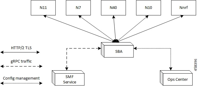
            mtls-enable [ true | false ] 
               certificate name [ clientCert | prem-server-cert | serverCert | x1client | x1server ] 
            end 

NOTES:

  • endpoint sbi : Configure the endpoint for the LI interface.

  • interface [ bfd | bgp | coa-nas | geo-external | geo-internal | gtpu | n4 | n7 | n10 | n11 | n16 | n40 | nrf | s2b | s5 | s5e | s8 | s11 | sxa | x1 | x2 ] : Specify the SBI interface for the configured endpoint.

  • mtls-enable [ true | false ] : Configure mTLS to provide a transport layer encryption between the nodes for the security compliance purposes. By default, the value of mtls-enable is configured to false .

  • certificate name [ clientCert | prem-server-cert | serverCert | x1client | x1server ] : Specify the alias name for certificate from the available options. SMF uses the certificate name for HTTPS messages. The certificate name is used during the start-up of REST-EP pods to configure the SSL context and TLS handshake when messages are exchanged on the SBI interfaces.

Verifying Configured Certificates

Use the show running-config endpoint sbi command to verify the certificates configured on the SBA interface.

The following is an example output of the show running-config endpoint sbi command.

smf# show running-config endpoint sbi 
   endpoint sbi 
      replicas         2 
      uri-scheme       https 
      certificate-name smf-server 
      vip-ip 209.165.200.225 
   exit 
Monitoring and Troubleshooting

This section provides information for troubleshooting any issues that might arise during the feature operation.

The SMF maintains various logs such as trace logs, event logs, and so on. Check the datastore pod health and the logs for any issues that are related to failures with message routing. Use information in the logs for diameter-ep-rx and datastore or session DB pods to debug issues with this feature.

show nf-tls certificate-status

To see the list of certificates, which are configured and their remaining validity period in days, use the following command:

show nf-tls certificate-status

Following is the sample output:

CERTIFICATE
NAME         DAYS
-------------------
ca           3631
smf-server   355
smfclient    355

SCP Interface

The Service Communication Proxy (SCP) is the routing control point that mediates all signaling and Control Plane messages in the network core. SCP is responsible for optimizing routing of NF discovery requests to the Network Repository Function (NRF), load balancing, traffic prioritization, and message management.

Communication Models for NF and NF Services Interaction

For a 3GPP 5GC enhanced SBA (eSBA) network, 3GPP defines four communication models that NF and NF services (Consumer NF and a Producer NF) can use to interact which each other. These communication models are Model A, B, C, and D.


Note


SMF supports Models A, B, and D.


The following table lists the communication models, their usage, and how they relate to the usage of an SCP.

Table 105. Communication Models for NF and NF Services Interaction

Communication Between Consumer NF and Producer NF

Service Discovery and Request Routing

Communication Model

Direct communication

No NRF or SCP; direct routing

A

Discovery using NRF services, no SCP; direct routing

B

Indirect communication

Discovery using NRF services; selection for specific instance from the set can be delegated to SCP. Routing is done through SCP.

C

Discovery and associated selection delegated to an SCP using discovery and selection parameters in service request. Routing is done through SCP.

D

Figure 42. Communication Models for NF and NF Services Interaction

In Model A, there is a direct communication without the NRF interaction. No NRF or SCP is used. The consumers are configured with the producer NF profiles and directly communicate with the producer of their choice.

In Model B, there is a direct communication with the NRF interaction. Consumers perform discovery by querying the NRF. Based on the discovery result, the consumer does the selection. The consumer sends the request to the selected producer.

In Model C, there is an indirect communication without the delegated discovery. Consumers perform discovery by querying the NRF. Based on discovery result, the consumer does the selection of an NF Set or a specific NF instance of NF set. The consumer sends the request to the SCP containing the address of the selected service producer pointing to a NF service instance or a set of NF service instances. The SCP routes the request to the selected NF service producer instance.

In Model D, there is an indirect communication with the delegated discovery. Consumers do not perform any discovery or selection. The consumer adds the required discovery and selection parameters to find an appropriate producer to the service request. The SCP uses the request address and the discovery and selection parameters in the request message to route the request to a appropriate producer instance. The SCP can perform discovery with an NRF and obtain a discovery result.

Indirect Communication for NFs through SCP Model D

Feature Description

SMF performs indirect communication for network functions (NFs) through Model D. By default, SMF performs the NRF discovery to select the NF peer, such as PCF, CHF, and AMF. If the NRF discovery fails and if the local configuration is available for the peer, SMF selects the local configured peer.


Note


In a network, SMF supports 12 SCPs theoretically and up to 5 SCPs in the practical scenarios.


How it Works

With the SCP Model D support, the SMF send requests to SCP endpoints. SCP performs the NRF discovery and finds the correct peer NF and sends the request to the NF. For the NRF discovery, the discovery parameters are sent in the HTTP header.

You can configure the indirect communication through Model D per peer type and by priority. You can configure the priority for Models A, B, and D.

Standards Compliance

The indirect communication for NFs through SCP Model D feature complies with the following standards:

  • 3GPP TS 29.500, version 16.9.0.

Supported HTTP Headers
3gpp-Sbi-Discovery Header

If you have configured the Model D, the SMF doesn't trigger the NF discovery and sends the message with the discovery parameters to SCP for the peer selection.

By default, SUPI and target NF type are added. SMF includes the 3gpp-Sbi-Discovery HTTP header for each query parameter that is configured in the network element profile in following format:

3gpp-Sbi-Discovery-<query-param>

Following are the examples of the 3gpp-Sbi-Discovery header:

3gpp-Sbi-Discovery-dnn: internet
3gpp-Sbi-Discovery-snssais: [{"sst": 1, "sd": "A08923"}, {"sst": 1, "sd": "0023F1"}]

Note


  • Both 3gpp-Sbi-Discovery-target-plmn and 3gpp-Sbi-Discovery-source-plmn are always included for the inter-PLMN discovery. However, these parameters aren't supported.

  • The 3gpp-Sbi-Discovery-supi header must be added to all the messages.


Authority Header

SMF includes the authority HTPP header in the messages to SCP. This header is populated in the following cases:

  • If the scheme is "https" from the configuration, then the authority header carries the FQDN from the endpoint name configuration.

  • If the scheme is "http", then the authority carries the FQDN or IP address. The priority is given to the IP address configuration.

3gpp-Sbi-Target-apiRoot Header

While sending notification to peer NF, the SMF replaces the "api root" of the "target api" with the "scp api root" and includes the "target api root" in the "3gpp-sbi-target-apiRoot" header.

For example, if the SMF sends the notification "POST https://scp.com/a/b/c/notification" to the SCP, with the "3gpp-sbi-target-apiRoot" header set to "https://example.com", then the SCP sends the request "POST https://example.com/a/b/c/notification" to the NF Service Producer, without the "3gpp-sbi-target-apiRoot" header.


Note


SMF doesn't support the SCP "apiPrefix".


The SMF doesn't include the "3gpp-sbi-target-apiRoot" header in the initial request to the peer NF for a specific session. SMF extracts the "target api" prefix of the resource from the "location" header of the response. Then, SMF includes this prefix in the "3gpp-sbi-target-apiRoot" header in a subsequent message to the peer NF for the same session.

For example, when the SMF receives the following "location" header in the N7 Create Response:

http://209.165.200.230:9082/npcf-smpolicycontrol/v1/sm-policies/ism.14.imsi-310260157090153.1660028704.43993.7129768994171956185

Then, the SMF sends the following SMPolicy Update message:

http://scpIP:port/npcf-smpolicycontrol/v1/sm-policies/ism.14.imsi-310260157090153.1660028704.43993.7129768994171956185

Where

"authority header" is "scpIP"

"3gpp-sbi-target-apiRoot" is 209.165.200.230:9082


Note


SMF also includes "3gpp-sbi-target-apiRoot" header in the messages that are intended to operate on a resource that the peer has already created. For example, when the SMF sends the N10 Deregistration message to UDM, the SMF uses the "location" header that the SMF receives in N10 Registration response to populate the "3gpp-sbi-target-apiRoot" header.


3gpp-Sbi-Callback Header

The SMF populates the "3gpp-Sbi-Callback" header in the callback requests with the callback service name for the SCP to provide the differentiated services.

Following is the format of this header:

"N<NF>_<service name>_<name of the callback service operation in the corresponding OpenAPI specification file>"

Some of the examples are as follows:

  • Notification to AMF is sent as "Nsmf_PDUSession_smContextStatusNotification"

  • Notification to vSMF is sent as "Nsmf_PDUSession_StatusNotify"

Server Header

The SMF includes "Server" header in all the error responses to peer NF for information on the source of error. Following is the format of this header:

UDM:"nf-instance-id"

For example, UDM:"54804518-4191-46b3-955c-ac631f953ed8"

On receiving an error response, SMF as a client, extracts the NFType from the "Server" header and triggers the SCP failure handling. If you have configured the Model D and if the "Server" header indicates the NF peer, then the SMF ignores the "retry" failure handling action. If you have configured "retry-fallback" as SCP failure handling, then SMF falls back to the local configuration without any retry action. After the SMF fallback, any failure is handled according to the NF failure handling configuration.


Note


  • If the "Server" header is not received or a timeout occurs, the SCP failure handling is applied.

  • In case of timeout from a peer, the SCP populates the "Server" header with its own FQDN and the "504" error code is returned with the problem details including the cause, which is set to "TARGET_NF_NOT_REACHABLE". In this case too, the SCP failure handling is applied. Based on the configuration, SCP tries all the available peer NFs. If the SCP doesn't find any available peer NF, the SCP responds with the "504" error code and "TARGET_NF_NOT_REACHABLE" cause. However, there is a possibility that other SCPs may be able to reach the peer. If a use case to not try another SCP exists in such a case, an operator can configure the retry value to 0.

  • In case of NF discovery errors between SCP and NRF, the SCP can set the cause as "NRF_NOT_REACHABLE" or "NF_DISCOVERY_ERROR". In such cases, the SMF falls back to Model-A, if configured.


3gpp-Producer-id Header

The SMF stores the "3gpp-producer-id" header that the SMF receives in the response from the NF peer. Then, the SMF includes this header in the subsequent messages to the peer NF for the same service for the same session.

SCP Model-D Fallback

If you have configured the SCP failure handling with the "retry" action, then SMF attempts an alternate SCP based on SCP configuration and the retry count configuration. After completion of the configured retry counts or unavailability of any alternate SCPs for retrying, the SMF does a fallback from model-D to model-A in the following scenarios:

  • SCP triggers an error, with the "Server" header indicating "scp".

  • The "retry-and-fallback" action is configured.

  • NF client configuration for the peer is available.

Enabling SCP Model D

Perform the following procedures to enable the SCP model D feature:

  • Configuring NF Selection Model

  • Configuring SCP Profile

Configuring NF Selection Model

You must configure an NF selection model to enable the SCP model D feature in the network element profile. To enable SCP model D, use the following sample configuration:

config 
   profile network-element network_element_name 
      nf-client-profile client_profile_name 
      failure-handling-profile failure_handling_profile_name 
      nf-selection-model 1 model1_name 
      nf-selection-model 2 model2_name 
   exit 

NOTES:

  • nf-selection-model 1 model1_name : Specify SCP as the first NF selection model.

  • nf-selection-model 2 model2_name : Specify another NF selection model, such as local, for the second NF selection model.

Configuring SCP Profile

You must configure an SCP profile under the DNN profile to enable the SCP model D feature . To enable SCP profile under the DNN profile, use the following sample configuration:

config 
   profile dnn dnn_name 
      network-element-profiles udm udm_profile_name 
      network-element-profiles scp scp_profile_ 
   exit 

NOTES:

  • network-element-profiles udm udm_profile_name : Specify the UDM profile name.

  • network-element-profiles scp scp_profile_ : Specify the SCP profile name that is to be configured under the specific UDM profile.

Configuration Example

The following is an example configuration of enabling SCP model D in the network element profile:

profile network-element pcf pcf1
 nf-client-profile PP1
 failure-handling-profile FHPCF
exit
profile network-element pcf pcf1-scp
 nf-client-profile PP1
 failure-handling-profile FHPCF
 nf-selection-model 1 scp
 nf-selection-model 2 local
exit  

The following is an example configuration of enabling SCP model D by adding the SCP profile under the DN profile:

profile dnn ims
 network-element-profiles udm udm-scp
 network-element-profiles scp scp-udm
exit  
Configuring SCP Failure Handling Profile

You can configure one or multiple SCPs in SMF similar to configuring NFs. You can configure an SCP endpoint per service under the SCP profile. To configure SCP failure handling profile, use the following sample configuration:

config 
   profile network-element scp scp_profile_name 
      nf-client-profile scp_client_profile_name 
      failure-handling-profile failure_handling_scp_profile_name 
      end 

NOTES:

  • profile network-element scp scp_profile_name : Specify the SCP as the network element profile. scp_profile_name must an alphanumeric string representing the corresponding network element profile name.

  • nf-client-profile scp_client_profile_name : Specify the SCP client profile.scp_client_profile_name must an alphanumeric string representing the corresponding NF client profile name.

  • failure-handling-profile failure_handling_scp_profile_name : Specify the SCP failure handling network profile for the configured SCP. failure_handling_scp_profile_name must an alphanumeric string representing the corresponding SCP failure handling network profile name.

Configuration Example

The following is an example configuration of the SCP failure handling profile:

profile network-element scp scp1
    nf-client-profile scp_profile1
    failure-handling-profile FHSCP
 exit
 
Configuring SCP for NF Communication

To configure SCP for NF communication, use the following sample configuration:

config 
   profile nf-client nf-type scp 
      scp-profile scp_profile_name 
         locality locality_name 
            prioritypriority_value 
            service name type service_name_type_value 
               responsetimeout  responsetimeout_value 
               endpoint-profile endpoint-profile_name 
                  capacity capacity_value 
                  priority priority_value 
                  uri-scheme uri_scheme_value 
                  endpoint-name endpoint_name/* FQDN */  
                     priority priority_value 
                     capacity endpoint-profile_name 
                     primary ip-address ipv4 ipv4_address 
                     primary ip-address port port_number 
                     end 

NOTES:

  • scp-profile scp_profile_name : Specify the name of the SCP profile.

  • locality locality_name : Specify the locality of SCP.

  • prioritypriority_value : Specify the priority value.

  • service name type service_name_type_value : Specify the service name type.

  • responsetimeout responsetimeout_value : Specify the response timeout value.

  • endpoint-profile endpoint-profile_name: Specify the SCP endpoint profile name.

  • primary ip-address ipv4 ipv4_address : Specify the IPv4 address of the primary endpoint.

  • primary ip-address port primary_port_number : Specify the port number of primary endpoint.

Configuration Example

The following is an example configuration of the SCP for NF communication:

profile nf-client nf-type scp
 scp-profile scp-profile1
  locality LOC1
   priority 30
   service name type <>
    responsetimeout 4000
    endpoint-profile EP1
     capacity 30
     priority 10
     uri-scheme http
     endpoint-name <> /* FQDN */
      priority 10
      capacity 50
      primary ip-address ipv4 209.165.202.133
      primary ip-address port 8080
     exit
    exit
   exit
  exit
 exit
exit
 
Configuring SCP Model D Fallback

To configure the SCP Model D fallback, use the following sample configuration:

config 
   profile nf-client-failure nf-type scp  
      profile failure-handling failure_handling_name 
      service name type npcf-smpolicycontrol  
         responsetimeout response_timeout_value 
         message type { PcfSmpolicycontrolCreate } 
         status-code httpv2 status_code 
         retry retry_value 
         action [ retry-and-fallback | retry-and-continue | continue | terminate { nfaction terminate } | retry-and-terminate { nfaction terminate } ] 
      exit 
   exit 

NOTES:

  • profile nf-client-failure nf-type scp : Specify the NF type as SCP that is required after the NF client failure.

  • service name type npcf-smpolicycontrol : Specify the service name type as npcf-smpolicycontrol.

  • responsetimeout response_timeout_value : Specify the response timeout value in seconds.

  • message type { PcfSmpolicycontrolCreate } : Specify the message type as PcfSmpolicycontrolCreate .

  • status-code httpv2 status_code : Specify the status code of the service. The status_code must be an integer in the range of 0–599.

  • retry retry_value : Specify the number of retry attempts to the different available endpoints. The retry_value must be an integer in the range of 1–10.

  • action [ retry-and-fallback | retry-and-continue | continue | terminate { nfaction terminate } | retry-and-terminate { nfaction terminate } ] : Specify the action as retry and fallback, retry-and-continue, continue, terminate, or retry and terminate for fallback from SCP Model D to Model A. The NF failure action used if the server header indicates that the action is from the NF peer. Action is used if the failure is from the SCP.


    Note


    • After a fallback, the subsequent messages for the same resource use the peer selected as part of fallback. For example, in case a fallback to SCP Model A happens during N10 registration, the SMF sends the subsequent N10 deregistration to the UDM selected as part of fallback.

    • Currently, the action [ retry-and-fallback ] is recommended only for the SCP NF client failure handling template.


Configuration Example

The following is an example configuration of the SCP Model D fallback:

config 
   profile nf-client-failure nf-type scp  
      profile failure-handling FHSCP  
      service name type npcf-smpolicycontrol 
         responsetimeout 1800  
         message type PcfSmpolicycontrolCreate 
         status-code httpv2 504  
            retry 1  
            action retry-and-fallback 
         exit 
      exit 
Dead SCP Detection

The existing dead peer detection framework in SMF is extended to detect a dead SCP.

Configuring Interfaces

To configure the endpoints for the SMF service and the interfaces to facilitate communication with other network functions, use the following sample configuration:

config 
   instance instance-id instance_id 
      endpoint { bgpspeaker |  dns-proxy | geo | gtp | gtpprime | li | nodemgr | pfcp | protocol | radius | radius-dns | sbi | service | sgw-service } 
         replicas replica_id 
         instancetype Dual 
         nodes node_id 
         interface { bfd | bgp | coa-nas | geo-external | geo-internal | gtpu | n4 | n7 | n10 | n11 | n16 | n40 | nrf | s2b | s5 | s5e | s8 | s11 | sxa } 
            loopbackPort port_number 
            vip-ip ipv4_address vip-port ipv4_port_number 
            vip-ip6 ipv6_address vip-ipv6-port ipv6_port_number 
            end 

NOTES:

  • endpoint { bgpspeaker | dns-proxy | geo | gtp | gtpprime | li | nodemgr | pfcp | protocol | radius | radius-dns | sbi | service | sgw-service } : Configure the endpoint based on the desired service.

  • interface { bfd | bgp | coa-nas | geo-external | geo-internal | gtpu | n4 | n7 | n10 | n11 | n16 | n40 | nrf | s2b | s5 | s5e | s8 | s11 | sxa } : Specify the interface for the configured endpoint.

  • vip-ip ipv4_address vip-port ipv4_port_number : Specify the IPv4 address and port of the interface.

    ipv4_address must be an IPv4 address in a dotted decimal notation.

  • vip-ip6 ipv6_address vip-ipv6-port ipv6_port_number : Specify the IPv6 address and port of the interface.

    ipv6_address must be an IPv6 address in colon-separated hexadecimal notation.

    At a given time, the SBI interfaces (N7, N10, N11, and N40) support only the IPv4 or IPv6 address. However, the N3, N4 and GTPC interfaces support either IPv4 or IPv6 address or both.


    Note


    For 4G calls with legacy interfaces, peer SGW IPv4, IPv6, or IPv4v6 data address is supported.


    Important


    Instance type must be configured as Dual to configure IPv6 for any interface, regardless of the interface supporting IPv4 or IPv6 at a time, or both IPv4 and IPv6 at the same time. This should be configured only at the endpoint level. All the interfaces configured under that endpoint will implicitly be configured as Dual type instance.

    VIP IP or VIP IPv6 configured under SBI interfaces always override the VIP IP and VIP IPv6 configured at the endpoint level.

    For the N4 and GTPC interfaces, the IP addresses (either IPv4 or IPv6 or both) configured under the interfaces overrides only the same type of IP address configured under an endpoint.


  • Since simultaneous IPv4 and IPv6 addresses aren’t supported for SBI interfaces, the discovery address transport type should be the same as the transport type configured at the endpoint or interface configuration.

  • Configure the ports, IPv4, and IPv6 addresses at both endpoint and interface levels. The VIP IP and port combination must be unique across the interfaces. If the interface level configuration isn’t available, the endpoint level configuration is considered.

Configuration Example

The following is an example of the IPv4 or IPv6 configuration for the interfaces.

config
 instance instance-id 1
  endpoint sbi
   replicas     1
   instancetype Dual
   nodes        1
   loopbackPort 7091
   vip-ip 209.165.200.225 vip-port 1234  
   vip-ipv6 2001:DB8:1::1 vip-ipv6-port 2345
  interface nrf
   loopbackPort 7096
   vip-ip 209.165.200.226 vip-port 1235  
  interface n11
   loopbackPort 7094
   vip-ip6 2001:DB8:0:ABCD::1 vip-ipv6-port 1212
   exit
  interface n7
   loopbackPort 7092
   vip-ip6 2001:DB8:1::FFFF vip-ipv6-port 1233
   exit
  interface n10
   loopbackPort 7093
   vip-ip 209.165.200.227 vip-port 4321  
   exit
  interface n40
   loopbackPort 7095
   vip-ip 209.165.200.228 vip-port 4231  
   end

Since dual stack is not supported, the NRF discovery address transport type must be the same as the transport type configured at endpoint or interface level configuration.

In the preceding configuration example, the PCF uses IPv6 address which is the same transport type as configured within the PCF profile.


config
 profile nf-client nf-type pcf
  pcf-profile PP100
   locality LOC1
    priority 30
    service name type npcf-smpolicycontrol
     endpoint-profile EP1
      capacity   30
      uri-scheme http
      endpoint-name EP1
       priority 56
       primary ip-address ipv6 2001:DB8:1::FEFF
       primary ip-address port 2223
      exit
      endpoint-name exit
      exit
     exit
    exit
 exit
exit

The following is an example of IPv6 configuration within UPF profile for the N4 interface.


config
 profile network-element upf UPF1
  node-id           SSI-UPF1
  n4-peer-address ipv6 2001:DB8:0:ACBD::1
  n4-peer-port      8805
  upf-group-profile upg1
  dnn-list          [ emergency intershat test ]
  capacity          1
  priority          100
  exit
 exit
exit

Configuration Verification

To verify the interface configuration, use the following commands:

show running-config instance instance-id instance_id endpoint endpoint_name interface interface_name 
[smf] smf# show running-config instance instance-id 1 endpoint sbi interface nrf
instance instance-id 1
 endpoint sbi
  interface nrf
   loopbackPort 9050
   dscp         24
   vip-ip 209.165.200.232 vip-port 8095
  exit
 exit
exit
[smf] smf# 

This example output shows the configuration for NRF interface. The value for vip-ip command indicates that the IPv4 address is configured for the NRF interface.

show peer 
Thu Jul  7  07:53:23.422 UTC+00:00
GR                                                                        POD                CONNECTED                                                 INTERFACE       
INSTANCE  ENDPOINT      LOCAL ADDRESS    PEER ADDRESS          DIRECTION  INSTANCE     TYPE  TIME        RPC     ADDITIONAL DETAILS                    NAME       VRF  
-----------------------------------------------------------------------------------------------------------------------------------------------------------------------
0         RadiusServer  -                10.1.4.72:1812        Outbound   radius-ep-0  Udp   6 days      Radius  Status: Init,Type: Auth               <none>     NA   
0         RadiusServer  -                10.1.4.72:1813        Outbound   radius-ep-0  Udp   6 days      Radius  Status: Init,Type: Acct               <none>     NA   
1         <none>        192.168.47.245   10.1.4.72:9014        Outbound   rest-ep-0    Rest  6 days      CHF     <none>                                n40        NA   
1         <none>        192.168.47.245   10.1.4.72:9024        Outbound   rest-ep-0    Rest  6 days      CHF     <none>                                n40        NA   
1         <none>        192.168.47.235   10.1.4.72:9011        Outbound   rest-ep-1    Rest  6 days      UDM     <none>                                n10        NA   
1         <none>        192.168.47.235   10.1.4.72:9012        Outbound   rest-ep-1    Rest  6 days      AMF     <none>                                n11        NA   
1         <none>        192.168.47.235   10.1.4.72:9060        Outbound   rest-ep-1    Rest  6 days      SEPP    <none>                                n32        NA   
1         <none>        192.168.47.235   10.1.4.72:9010        Outbound   rest-ep-1    Rest  6 days      NRF     <none>                                nrf        NA   
1         <none>        192.168.47.235   10.1.4.72:9013        Outbound   rest-ep-1    Rest  6 days      PCF     <none>                                n7         NA   
1         <none>        192.168.47.245   10.1.4.72:9010        Outbound   rest-ep-0    Rest  6 days      NRF     <none>                                nrf        NA   
1         <none>        192.168.47.245   10.1.4.72:9011        Outbound   rest-ep-0    Rest  16 minutes  UDM     <none>                                n10        NA   
1         <none>        192.168.47.245   10.1.4.72:9012        Outbound   rest-ep-0    Rest  6 days      AMF     <none>                                n11        NA   
1         <none>        192.168.47.245   10.1.4.72:9060        Outbound   rest-ep-0    Rest  6 days      SEPP    <none>                                n32        NA   
1         <none>        192.168.47.235   10.1.4.72:9024        Outbound   rest-ep-1    Rest  6 days      CHF     <none>                                n40        NA   
1         <none>        192.168.47.235   10.1.4.72:9014        Outbound   rest-ep-1    Rest  6 days      CHF     <none>                                n40        NA   
1         <none>        192.168.47.245   10.1.4.72:9013        Outbound   rest-ep-0    Rest  6 days      PCF     <none>                                n7         NA   
1         S2B           10.1.3.236:2123  172.31.4.72:2123      Inbound    nodemgr-0    Udp   6 days      ePDG    MaxRemoteRcChange: N/A,Recovery: 100  S2B        NA   
1         S2B           [1111::10:1:3:236]:2123       [1111::10:1:4:72]:2123  Inbound    nodemgr-0    Udp   6 days      ePDG    MaxRemoteRcChange: N/A,Recovery: N/A  S2B        NA   
1         S2B           [1111::10:1:3:236]:2123       [1111::10:1:4:72]:2123  Inbound    nodemgr-1    Udp   6 days      ePDG    MaxRemoteRcChange: N/A,Recovery: N/A  S2B        NA

OAM Support

This section describes operations, administration, and maintenance information regarding support for interfaces in SMF.

Bulk Statistics Support

The following label is added into the existing statistics smf_restep_http_msg_total :

uri_version_mismatch —This metric is included when the URI version in an incoming message is not found in the configured URI versions in SMF.

OFCS_CDR_DROP_STATS — This metric is added to capture counter values whenever a CDR is suppressed due to Zero Suppression.

It displays the SMF procedure name along with trigger name when the suppression criterion is met.

Trigger names values are would be one of these:

  • final-cdr

  • external-trigger-cdr

  • internal-trigger-cdr