Simplified Cisco IoT FND Architecture

Tunnel management with a unique Pre-Shared Key (PSK) and the assignment of IP addresses using Cisco IoT FND IP Address Management (IPAM) aims to simplify the configuration process and reduce the number of components in Cisco IoT FND. In the simplified architecture, the PSK replaces existing security components such as CA, AAA, and RA, while the IPAM replaces the external DHCP server. This simplified architecture is supported only in greenfield deployments using VMs with a Postgres database, and is designed for router management only.

However, you have the discretion to use a unique PSK and the IPAM in the architecture. Cisco IoT FND continues to support existing PKI-based certificate communication between FAR and Cisco IoT FND, PKI-based certificates for tunnels between FAR and HER, and external DHCP servers for tunnel IP addressing.

Tunnel Management with Pre-Shared Key

A unique pre-shared key (PSK) solution is used for the tunnel management between FAR and HER, which significantly simplifies the authentication and authorization process in the headend infrastructure and allows the users to self-manage. The PSK is supported on all Cisco IOS and IOS-XE device types.

The table provides various scenarios where PSK can be used effectively in combination with either SUDI or a CA server in the greenfield deployment.

Deployment

Scenario

Recommendation

Greenfield deployment

Without CA server

  • Use PSK for authentication and authorization of communication between FAR and HER.

  • Use SUDI for authentication and authorization of communication between FND and FAR.

With CA server

Choose one of the following combinations:
  • Use PSK for authentication and authorization of communication between FAR and HER.

  • Use a custom CA certificate for authentication and authorization of communication between FND and FAR.

(or)

  • Use a custom CA certificate for authentication and authorization of communication between both FAR and HER, FND and FAR.

Note


In both scenarios, with or without CA server, it is mandatory to generate the IoT FND certificate from the CA server and install it on the IoT FND server (cgms_keystore).


Note


For the brownfield deployment, IoT FND continues to support CA, RA, and AAA for the FAR communication with FND and HER.


Configuring FND for Tunnel Management with PSK

Use the following steps to configure FND for managing tunnels with PSK.

Procedure


Step 1

Run the following script to configure FND with IPAM and PSK settings.

/opt/cgms/bin/setupCgms.sh

Step 2

On entering "y", you are provided with a new option to select PSK scheme for IPsec tunnel management.
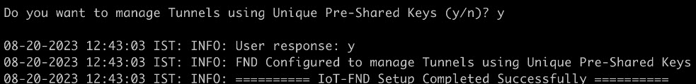
Step 3

On entering "y", FND is configured with PSK.

FND updates the Preferences table by setting the property com.cisco.cgms.pnp.tunnelMgmtUsingPsk as True. By default, this property is False.


Generating PSK

A unique pre-shared key is generated when you import a device through CSV or NB API. The pre-shared key is a 15-character alphanumeric string which is unique and generated randomly for each device. The generated key is encrypted and stored in the database for each router. For more information on tunnel management with PSK, see Workflow for Tunnel Management with PSK.

Default templates

Templates are used for pushing the configuration commands and data to devices from Cisco IoT FND. Templates help in configuring many devices simultaneously with a single file. Numerous templates are available for tunnel management based on different device configurations.

These default templates are available for tunnel management:

  • Router Tunnel Addition Template,

  • HER Tunnel Addition Template,

  • Router Bootstrap Configuration Template,

  • HER Tunnel FlexVPN Configuration Template.

Table 1. Feature History
Release Information

Feature Name

Description

Cisco IoT FND Release 4.11.0

Tunnel Management with pre-shared key (PSK)

PSK is used during the tunnel provisioning to authenticate the communication between FAR and HER. This feature reduces the certificate dependency for tunnel formation.

If PSK is enabled as part of Cisco IoT FND installation, then Cisco IoT FND generates a unique pre-shared key for each FAR in Cisco IoT FND.

.

Cisco IoT FND Release 5.1

Template Versioning

Template versioning allows you to create new Cisco IoT FND templates with unique version numbers from both existing as well as newly created templates.

You can create, edit, save or delete templates using template versioning in Cisco IoT FND.

Template versioning in Cisco IoT FND

Starting from the Cisco IoT FND release 5.1.0, you can create new templates with unique version numbers from both existing as well as newly created templates. You can use the templates for pushing configuration commands from Cisco IoT FND to devices.

Template versioning lets you track and manage changes to your configuration templates. You can save the latest template as a new version or choose to select an existing template from the previously saved versions for configuring devices in Cisco IoT FND.

Consider these points before using template versioning in Cisco IoT FND:

  • The template's version number is assigned automatically by Cisco IoT FND itself in a sequential order.

  • The first template which already exists is referred to as the default template.

  • The latest template version is auto-selected and appears in the combo box with a text area, which you can use for editing configuration details of any device.

  • Whenever Cisco IoT FND is upgrade to 5.1.0 from the earlier versions, then the previous version template appears as the latest template version in Cisco IoT FND 5.1.0. Also, the default template version is created based on the device types.

  • For config groups prior to Cisco IoT FND release 5.1.0, the latest template version will be version-2 and in Cisco IoT FND release 5.1.0 the default template is version-1.

  • For tunnel provisioning groups, prior to Cisco IoT FND release 5.1.0, the latest template version will be version-1 and in Cisco IoT FND release 5.1.0 the default template is version-0.

  • Template versioning does not apply to individual devices and you need to consider this before using the Device Info > Push Configuration option.

Supported devices

Template versioning is enabled for these devices in Cisco IoT FND, which are running:

Table 2.

Software

Routers

Cisco IOS XE

The supported routers running Cisco IOS XE:

  • Cisco Catalyst IR8100,

  • Cisco Catalyst IR1800,

  • Cisco Catalyst IR1100.

Cisco IOS

The supported running Cisco IOS:

  • Cisco Catalyst IR800,

  • Cisco Connected Grid Router CGR1000.

Benefits of template versioning

The template versioning feature allows you to:

  • Easily identify and manage previously used templates with different version numbers.

  • Reuse or modify configuration details of devices by creating a new template with the latest version.

  • Easily track modifications and revert to previously saved template configurations.

  • Refer to template changes for troubleshooting purposes.

Configure template using device configuration

Use this task to save a template.

Before you begin

You need to consider the following points before configuring and saving new templates:

  • When you edit or make changes to any existing template then that template becomes the latest template.

  • You can only save the latest version of the template which can be used to generate the next version of the template later.

  • All previous versions of the templates except the latest version will appear as read only templates and you cannot edit or modify these versions.

  • There is no maximum limit set for the number of templates that you can create at any given time.

  • You can save a new version of the template even if Target Firmware Version is changed in the Router Bootstrap Configuration tab.

  • The default template version is version-1 in CONFIG > Device Configuration page.

Procedure

Step 1

From the Cisco IoT FND menubar, select CONFIG > Device Configuration.

Step 2

Select the router from the router group.

Step 3

Click Edit Configuration Template.

Step 4

Edit the latest template using the text area which appears with the template.

Step 5

Click Save.


Cisco IoT FND saves the template as a new version with the latest version number.

Note


If you click Save without modifying the latest template, then you will receive a message stating that there were no changes made in the template. In this case, edit the template and then try saving it again.


What to do next
You can push the saved configuration in the template using the Push Configuration option, see Pushing Configurations to Routers.

Configure template using tunnel provisioning page

Use this task to save a template.

Before you begin

You need to consider the following points before configuring and saving new templates:

  • When you edit any existing template or make changes to the existing template then that template becomes the latest template.

  • You can only save the latest version of the template which can be used to generate the next version of the template later.

  • All previous versions of the templates other than the latest version will appear as read only templates and you cannot edit or modify them.

  • There is no maximum limit set for the number of templates that you can create at any given time.

  • The default template version is version-0 in the CONFIG > Tunnel Provisioning page.

Procedure

Step 1

From the Cisco IoT FND menubar, select CONFIG > Tunnel Provisioning page.

Step 2

Choose and click from the menu options as given:

  • Tunnel Provisioning > Router Tunnel Addition,

  • Tunnel Provisioning > HER Tunnel Addition,

  • Tunnel Provisioning > HER Tunnel Deletion,

  • Tunnel Provisioning > Router Bootstrap Configuration.

Step 3

Select router from the router group.

Step 4

Edit the latest template using the text area.

Step 5

Click Save.


The template is saved as a new template with the latest version number.

Note


If you click Save without modifying the latest template, then you will receive a message indicating there were no changes made in the template. In this case you can try creating the template once again.


What to do next
You can push the saved configuration in the template using the Push Configuration option, see Pushing Configurations to Routers.

View template using device configuration

Use this task to view template using device configuration option.

Procedure

Step 1

From the Cisco IoT FND menubar, select CONFIG > Device Configuration.

Step 2

Select router from the router group.

Step 3

Select the template version you want to view from the Template Version drop-down list.


You will see the template details displayed in the text area.

View template using tunnel provisioning

Use this task to view template using tunnel provisioning option.

Procedure

Step 1

From the Cisco IoT FND menubar, select CONFIG.

Step 2

From CONFIG page, choose and click from the menu options as given:

  • Tunnel Provisioning > Router Tunnel Addition,

  • Tunnel Provisioning > HER Tunnel Addition,

  • Tunnel Provisioning > HER Tunnel Deletion,

  • Tunnel Provisioning > Router Bootstrap Configuration.

Step 3

Select router from the router group.

Step 4

Select the template version you want to view from the Template Version drop-down list.


You will see the template details displayed in the text area.

Delete template

Use these steps to delete a template.

Before you begin

You cannot delete the latest template and the default template versions as the delete button is disabled for these versions.

You can access the template versioning combo box , by selecting one of these two navigation paths in Cisco IoT FND from the Cisco IoT FND menubar:

  • CONFIG > Device Configuration.

  • CONFIG >

    • Tunnel Provisioning > Router Tunnel Addition,

    • Tunnel Provisioning > HER Tunnel Addition,

    • Tunnel Provisioning > HER Tunnel Deletion,

    • Tunnel Provisioning > Router Bootstrap Configuration.

Procedure

Step 1

From the template versioning combo box select a template version.

Step 2

Click Delete.


The template is deleted.

Router tunnel addition template

There are two default router addition templates available for authentication. Based on the configuration settings in setupCgms.sh, the default template is selected to manage tunnels using PSK.

Configure router tunnel addition using template

Use this task to configure the router tunnel addition using template.

Before you begin

Note


By default, the peer name is set to her-tunnel in crypto ikev2 keyring FlexVPN_Keyring and Flexvpn_ikev2_profile. You can configure the peer name to match the name that is given in identity local key-id in the HER configuration.
Procedure

Step 1

Edit the template as given in the example to configure router tunnel addition.

Example:
<#-- This template only supports FARs running IOS. -->
<#if !far.isRunningIos()>
  ${provisioningFailed("FAR is not running IOS")}
</#if>
 
<#--
  For FARs running IOS configure a FlexVPN client in order to establish secure
  communications to the HER. This template expects that the HER has been
  appropriately pre-configured as a FlexVPN server.
-->
<#if far.isRunningIos()>
  <#assign sublist=far.eid?split("+")[0..1]>
  <#assign sn=sublist[1]>
  <#--
    Configure a Loopback0 interface for the FAR.
  -->
  interface Loopback0
    <#--
      If the loopback interface IPv4 address property has been set on the CGR
      then configure the interface with that address. Otherwise obtain an
      address for the interface now using DHCP.
    -->
    <#if far.loopbackV4Address??>
      <#assign loopbackIpv4Address=far.loopbackV4Address>
    <#elseif far.isIPAMForLoopbackSelected()??>
      <#assign loopbackIpv4Address=far.IPAMForLoopbackIpv4()>
    <#else>
      <#--
        Obtain an IPv4 address that can be used to for this FAR's Loopback
        interface. The template API provides methods for requesting a lease from
        a DHCP server. The IPv4 address method requires a DHCP client ID and a link
        address to send in the DHCP request. The 3rd parameter is optional and
        defaults to "IoT-FND". This value is sent in the DHCP user class option.
        The API also provides the method "dhcpClientId". This method takes a DHCPv6
        Identity association identifier (IAID) and a DHCP Unique IDentifier (DUID)
        and generates a DHCPv4 client identifier as specified in RFC 4361. This
        provides some consistency in how network elements are identified by the
        DHCP server.
      -->
      <#assign loopbackIpv4Address=far.ipv4Address(dhcpClientId(far.enDuid,0),far.dhcpV4LoopbackLink).address>
    </#if>
    ip address ${loopbackIpv4Address} 255.255.255.255
    <#--
      If the loopback interface IPv6 address property has been set on the CGR
      then configure the interface with that address. Otherwise obtain an
      address for the interface now using DHCP.
    -->
    <#if far.loopbackV6Address??>
      <#assign loopbackIpv6Address=far.loopbackV6Address>
    <#elseif far.isIPAMForLoopbackSelected()??>
      <#assign loopbackIpv6Address=far.IPAMForLoopbackIpv6()>
    <#else>
      <#--
        Obtain an IPv6 address that can be used to for this FAR's loopback
        interface. The method is similar to the one used for IPv4, except clients
        in DHCPv6 are directly identified by their DUID and IAID. IAIDs used for
        IPv4 are separate from IAIDs used for IPv6, so we can use zero for both
        requests.
      -->
      <#assign loopbackIpv6Address=far.ipv6Address(far.enDuid,0,far.dhcpV6LoopbackLink).address>
    </#if>
    ipv6 address ${loopbackIpv6Address}/128
  exit
 
  <#--
    Default to using FlexVPN for the tunnel configuration of FARs running IOS.
  -->
 <#if (far.useFlexVPN!"true") = "true">
    <#--
      IPv4 ACL which specifies the route(s) FlexVPN will push to the HER.
      We want the HER to know the route to the CGR's loopback interface.
    -->
    ip access-list standard FlexVPN_Client_IPv4_LAN
      permit ${loopbackIpv4Address}
    exit
 
    <#--
      IPv6 ACL which specifies the route(s) FlexVPN will push to the HER.
      We want the HER to know the route to the CGR's loopback interface.
      If a mesh has been configured on this CGR we want the HER to know the route to the mesh.
    -->
    ipv6 access-list FlexVPN_Client_IPv6_LAN
      <#if far.meshPrefix??>
        permit ipv6 ${far.meshPrefix}/64 any
      </#if>
      sequence 20 permit ipv6 host ${loopbackIpv6Address} any
    exit
 
    <#--
      FlexVPN authorization policy that configures FlexVPN to push the CGR LAN's
      specified in the ACLs to the HER during the FlexVPN handshake.
    -->
    crypto ikev2 authorization policy FlexVPN_Author_Policy
      route set access-list FlexVPN_Client_IPv4_LAN
      route set access-list ipv6 FlexVPN_Client_IPv6_LAN
      route set interface
    exit
 
    crypto ikev2 proposal FlexVPN_IKEv2_Proposal
      encryption aes-cbc-256
      group 14
      integrity sha256
    exit
    crypto ikev2 policy FLexVPN_IKEv2_Policy
      proposal FlexVPN_IKEv2_Proposal
    exit
 
    <#-- FlexVPN authorization policy is defined locally. -->
    aaa authorization network FlexVPN_Author local
 
    crypto ikev2 keyring FlexVPN_Keyring
      peer her-tunnel
        address ${far.ipsecTunnelDestAddr1}
        identity key-id her-tunnel
        pre-shared-key ${far.mgmtVpnPsk}
      exit
    exit
 
    crypto ikev2 profile FlexVPN_IKEv2_Profile
      match identity remote key-id her-tunnel
      identity local fqdn ${sn}.cisco.com
      authentication remote pre-share
      authentication local pre-share
      keyring local FlexVPN_Keyring
      dpd 120 3 periodic
      aaa authorization group psk list FlexVPN_Author FlexVPN_Author_Policy
    exit
 
    <#--
      If the headend router is an ASR then use a different configuration for the
      transform set as some ASR models are unable to support the set we'd prefer
      to use.
    -->
    <#if her.pid?contains("ASR")>
      crypto ipsec transform-set FlexVPN_IPsec_Transform_Set esp-aes esp-sha-hmac
        mode tunnel
      exit
    <#else>
      crypto ipsec transform-set FlexVPN_IPsec_Transform_Set esp-aes esp-sha256-hmac
        mode tunnel
      exit
    </#if>
 
    crypto ipsec profile FlexVPN_IPsec_Profile
      set ikev2-profile FlexVPN_IKEv2_Profile
      set pfs group14
      set transform-set FlexVPN_IPsec_Transform_Set
    exit
 
    <#assign wanInterface=far.interfaces(far.tunnelSrcInterface1!"Cellular")>
    interface Tunnel0
      description IPsec tunnel to ${her.eid}
      ip unnumbered loopback0
      ipv6 unnumbered loopback0
      tunnel destination dynamic
      tunnel protection ipsec profile FlexVPN_IPsec_Profile
      tunnel source ${wanInterface[0].name}
    exit
 
    <#if !(far.ipsecTunnelDestAddr1??)>
      ${provisioningFailed("FAR property ipsecTunnelDestAddr1 must be set to the destination address to connect this FAR's FlexVPN tunnel to")}
    </#if>
    crypto ikev2 client flexvpn FlexVPN_Client
      peer 1 ${far.ipsecTunnelDestAddr1}
      client connect Tunnel0
    exit
    ip http secure-client-auth
    no ip http tls-version TLSv1.2
  <#else>
    <#--
      Configure the tunnel using DMVPN.
    -->
    router eigrp 1
      network ${loopbackIpv4Address}
    exit
    ipv6 router eigrp 2
      no shutdown
    exit
    interface Loopback0
      ipv6 eigrp 2
    exit
    crypto ikev2 proposal DMVPN_IKEv2_Proposal
      encryption aes-cbc-256
      group 14
      integrity sha256
    exit
    crypto ikev2 policy DMVPN_IKEv2_Policy
      proposal DMVPN_IKEv2_Proposal
    exit
    crypto ikev2 keyring DMVPN_Keyring
      peer her-tunnel
        address ${far.ipsecTunnelDestAddr1}
        identity key-id her-tunnel
        pre-shared-key ${far.mgmtVpnPsk}
      exit
    exit
    crypto ikev2 profile DMVPN_IKEv2_Profile
      match identity remote key-id her-tunnel
      identity local fqdn ${sn}.cisco.com
      authentication remote pre-share
      authentication local pre-share
      keyring local DMVPN_Keyring
      dpd 120 3 periodic
    exit
    <#--
      If the headend router is an ASR then use a different configuration for the
      transform set as some ASR models are unable to support the set we'd prefer
      to use.
    -->
    <#if her.pid?contains("ASR")>
      crypto ipsec transform-set DMVPN_IPsec_Transform_Set esp-aes esp-sha-hmac
        mode tunnel
      exit
    <#else>
      crypto ipsec transform-set DMVPN_IPsec_Transform_Set esp-aes 256 esp-sha256-hmac
        mode tunnel
      exit
    </#if>
    crypto ipsec profile DMVPN_IPsec_Profile
      set ikev2-profile DMVPN_IKEv2_Profile
      set pfs group14
      set transform-set DMVPN_IPsec_Transform_Set
    exit
    <#if !(far.nbmaNhsV4Address??)>
      ${provisioningFailed("FAR property nbmaNhsV4Address has not been set")}
    </#if>
    <#if !(far.nbmaNhsV6Address??)>
      ${provisioningFailed("FAR property nbmaNhsV6Address has not been set")}
    </#if>
    <#assign wanInterface=far.interfaces(far.tunnelSrcInterface1!"Cellular")>
    interface Tunnel0
      <#assign lease=far.ipv4Address(dhcpClientId(far.enDuid,1),far.dhcpV4TunnelLink)>
      ip address ${lease.address} ${lease.subnetMask}
      ip nhrp map ${far.nbmaNhsV4Address} ${far.ipsecTunnelDestAddr1}
      ip nhrp map multicast ${far.ipsecTunnelDestAddr1}
      ip nhrp network-id 1
      ip nhrp nhs ${her.interfaces("Tunnel0")[0].v4.addresses[0].address}
      ipv6 address ${far.ipv6Address(far.enDuid,1,far.dhcpV6TunnelLink).address}/128
      ipv6 eigrp 2
      ipv6 nhrp map ${far.nbmaNhsV6Address}/128 ${far.ipsecTunnelDestAddr1}
      ipv6 nhrp map multicast ${far.ipsecTunnelDestAddr1}
      ipv6 nhrp network-id 1
      ipv6 nhrp nhs ${far.nbmaNhsV6Address}
      tunnel mode gre multipoint
      tunnel protection ipsec profile DMVPN_IPsec_Profile
      tunnel source ${wanInterface[0].name}
    exit
    router eigrp 1
      network ${lease.address}
    exit
  </#if>
</#if>

Step 2

Save the template.


HER tunnel addition template

Similar to Router Tunnel Addition templates, there are two default HER tunnel addition templates available. Based on the configuration settings in setupCgms.sh, the default template is selected to manage tunnels using PSK or not.

Configure HER tunnel addition template

Use this task to configure HER tunnel addition using template.

Procedure

Step 1

Edit the template as given in the example to configure HER tunnel addition.

Example:
per-Router HER Config

<#-- This template only supports HERs running IOS or IOS XE. -->
<#if !her.isRunningIos() && !her.isRunningIosXe()>
  ${provisioningFailed("HER is not running IOS or IOS XE")}
</#if>

<#if far.isRunningIos()>
  <#assign sublist=far.eid?split("+")[0..1]>
  <#assign sn=sublist[1]>

  crypto ikev2 keyring FlexVPN_Keyring
    peer ${sn}
      identity fqdn ${sn}.cisco.com
      pre-shared-key ${far.mgmtVpnPsk}
   exit
  exit
</#if>

Step 2

Save the template.


Router bootstrap configuration template


Note


For SUDI authentication, you must use cgna initiator profile as the tunnel profile.


Note


Based on the device types, the following ports are used:
  • For Cisco IOS-XE device types, use port 443.

  • For Cisco IOS device types, use port 8443.


Configure router bootstrap using template

Use this task to configure router bootstrap using template.

Procedure

Step 1

Edit the template as given in the example to configure router bootstrap.

Example:
<#assign sublist=far.eid?split("+")[0..1]>
<#assign pid=sublist[0]>
<#assign sn=sublist[1]> 

hostname ${sn}
!
aaa new-model
!
aaa authentication login default local
aaa authorization exec default local
!
aaa session-id common
aaa password restriction
!
ip host fnd.iot.cisco.com <fnd ip address>
ip domain name cisco.com
!
password encryption aes
!
!
archive
  path bootflash:archive/
maximum 8
!
username admin privilege 15 password <router password>
!
!
no cdp run
!
!
interface Loopback999
 ip address <ip address for the interface> 255.255.255.255
!
ip forward-protocol nd
!
no ip http server
ip http tls-version TLSv1.2
ip http authentication aaa login-authentication default
ip http secure-server
ip http secure-port 443 
ip http client source-interface lo0
ip http client secure-trustpoint CISCO_IDEVID_SUDI
 
ip ssh time-out 60
ip ssh authentication-retries 2
crypto key generate rsa
ip ssh version 2
!
ipv6 unicast-routing
!
control-plane
!
line con 0
length 0
transport preferred none
escape-character 3
stopbits 1

!

line vty 6 15
session-timeout 10
exec-timeout 5 0
session-limit 2
transport input ssh
!
wsma agent exec
profile exec
!
wsma agent config
profile config
!
!wsma agent filesys
!
!wsma agent notify
!
!
wsma profile listener exec
transport https path /wsma/exec
!
wsma profile listener config
transport https path /wsma/config

event manager directory user policy "flash:/managed/scripts"
event manager policy no_config_replace.tcl type system authorization bypass
!
!
cgna gzip
!
!
cgna initiator-profile cg-nms-tunnel
 add-command show hosts | format flash:/managed/odm/cg-nms.odm
 add-command show interfaces | format flash:/managed/odm/cg-nms.odm
 add-command show version | format flash:/managed/odm/cg-nms.odm
 add-command show ipv6 dhcp | format flash:/managed/odm/cg-nms.odm
 add-command show ipv6 interface | format flash:/managed/odm/cg-nms.odm
 callhome-url https://tps.iot.cisco.com:9120/cgna/ios/config
 execution-url https://<ip address of Loopback999 interface>:443/wsma/config
 interval 10
 gzip
 post-commands
 active

Step 2

Edit the template as given in the example to configure ACL optionally as an additional security step.

Example:
access-list 10 permit <IP address of TPS>
access-list 10 deny any

interface gigabitEthernet 0/0/0
ip access-group 10 in
exit

Note

 
  • In the above sample configuration, the communication with FAR is only through IP address of TPS until the tunnel is established.

  • You can also remove the ACL configuration using the command as given in the example, in the router tunnel addition template.

    no access-list 10
    interface gigabitEthernet 0/0/0
    no ip access-group 10 in
    exit

Step 3

Save the template.


HER tunnel FlexVPN configuration template

You can configure HER tunnel FlexVPN using a template.

Configure HER tunnel FlexVPN using template

Use this task to configure the HER tunnel FlexVPN using template.

Procedure

Step 1

Edit the template as given in the example to configure HER tunnel FlexVPN.

Example:
version 17.12
service timestamps debug datetime msec
service timestamps log datetime msec
platform qfp utilization monitor load 80
platform punt-keepalive disable-kernel-core
platform sslvpn use-pd
platform console virtual
!
hostname xxxxxxx
!
boot-start-marker
boot-end-marker
!
!
aaa new-model
!
!
aaa authentication login default local
aaa authentication login AUTH local
!......
........
crypto pki trustpoint SLA-TrustPoint
 enrollment pkcs12
 revocation-check crl
 hash sha256
!
!
crypto pki certificate chain TP-self-signed-141726200
 certificate self-signed 01
  xxxxxxxxxxxxxxxxxxxxxxxxxxxxxxxxxxxxxxxxxxxxxxxxxxxxxx
  xxxxxxxxxxxxxxxxxxxxxxxxxxxxxxxxxxxxxxxxxxxxxxxxxxxxxx
  xxxxxxxxxxxxxxxxxxxxxxxxxxxxxxxxxxxxxxxxxxxxxxxxxxxxxx
.......
  xxxxxxxxxxxxxxxxxxxxxxxxxxxxxxxxxxxxxxxxxxxxxxxxxxxxxx
  xxxxxxxxxxxxxxxxxxxxxxxxxxxxxxxxxxxxxxxxxxxxxxxxxxxxxx
  xxxxxxxxxxxxxx
        quit
crypto pki certificate chain SLA-TrustPoint
 certificate ca 01
  xxxxxxxxxxxxxxxxxxxxxxxxxxxxxxxxxxxxxxxxxxxxxxxxxxxxxx
  xxxxxxxxxxxxxxxxxxxxxxxxxxxxxxxxxxxxxxxxxxxxxxxxxxxxxx
.....
  xxxxxxxxxxxxxxxxxxxxxxxxxxxxxxxxxxxxxxxxxxxxxxxxxxxxxx
  xxxxxxxxxxxxxx
        quit
!
!
!
license udi pid C8000V sn 9OA9SRYYZVZ
license boot level network-advantage addon dna-advantage
memory free low-watermark processor 203066
diagnostic bootup level minimal
!
!
spanning-tree extend system-id
!
username xxxxxx privilege 15 password 0 xxxxxxxxxx
!
redundancy
!
crypto ikev2 authorization policy FlexVPN_Author_Policy
 route set interface
 route set access-list FlexVPN_Client_Default_IPv4_Route
!
crypto ikev2 redirect client
crypto ikev2 proposal FlexVPN_IKEv2_Proposal
crypto ikev2 profile FlexVPN_IKEv2_Profile
 match identity remote fqdn domain cisco.com
 identity local key-id CLUSTER-2
 authentication remote pre-share
 authentication local pre-share
 keyring local FlexVPN_Keyring
 dpd 120 3 periodic
 aaa authorization group psk list FlexVPN_Author FlexVPN_Author_Policy
 virtual-template 1 !
!......
........
!
crypto isakmp invalid-spi-recovery
!
!
crypto ipsec transform-set FlexVPN_IPsec_Transform_Set esp-aes esp-sha256-hmac
 mode transport
!
crypto ipsec profile FlexVPN_IPsec_Profile
 set transform-set FlexVPN_IPsec_Transform_Set
 set pfs group14
!.....
......
!
interface Loopback0
 ip address xx.xx.xx.xx 255.255.255.255
!
interface GigabitEthernet1
 ip address xx.xx.xx.xx 255.255.255.128
 negotiation auto
 no mop enabled
 no mop sysid
!
interface GigabitEthernet2
 ip address xx.xx.xx.xx 255.255.255.0
...
....
mgcp behavior rsip-range tgcp-only
mgcp behavior comedia-role none
mgcp behavior comedia-check-media-src disable
mgcp behavior comedia-sdp-force disable !
mgcp profile default
!
line con 0
 stopbits 1
line aux 0
line vty 0 4
 password cisco123
 transport input ssh
!
!
netconf legacy
netconf ssh
!
!
End

Step 2

Save the template.


HER tunnel deletion template


Note


Ensure that the keyring name mentioned in "crypto ikev2 keyring FlexVPN_Keyring" and "FlexVPN_IKEv2_Profile" match the HER keyring name.

Configure HER tunnel deletion using template

Use this task to configure HER tunnel deletion using template.

Procedure

Step 1

Edit the template as given in the example to configure HER tunnel deletion for HERs on Cisco IOS and Cisco IOS-XE.

Example:
Remove Router PSK config from HER
<#-- This template only supports HERs running IOS or IOS XE. -->
<#if !her.isRunningIos() && !her.isRunningIosXe()>
  ${provisioningFailed("HER is not running IOS or IOS XE")}
</#if>

<#if far.isRunningIos()>
  <#assign sublist=far.eid?split("+")[0..1]>
  <#assign sn=sublist[1]>

  crypto ikev2 keyring FlexVPN_Keyring
    no peer ${sn}
  exit
</#if>

Step 2

Save the template.


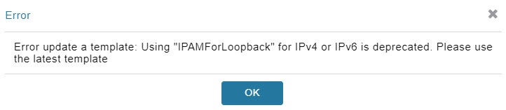
IPv4/IPv6 host resolution during device upgrade to Cisco IOS XE Release 17.12 and later releases

This task enables you to reliably manage hostname resolution on Cisco IOS XE devices across upgrades and downgrades by explaining the dual (split) versus single-line ip host behavior. This guidance helps you update templates, understand checkpoint/config file handling, and verify outcomes during tunnel provisioning and config pushes, avoiding configuration loss after upgrades.

Here is a list of context for you to keep in mind:

  • Applies to Cisco IOS-XE devices only.

  • Cisco IOS-XE Release 17.12 and earlier releases behavior: Devices use split host entries per IP family (dual entries). For example:
    ip host fnd.iot.cisco.com 198.51.100.10
    ip host fnd.iot.cisco.com 2001:db8:1000:10::10
  • Cisco IOS-XE Release 17.12 and later releases behavior: Devices expect a single host entry that combines IPv4 and IPv6 on the same line (single-line). For example:
    ip host fnd.iot.cisco.com 198.51.100.10 2001:db8:1000:10::10
  • When you upgrade a Cisco IOS XE device from 17.12 to later releases, the device continues to receive split host entries, the first entry is replaced by the second entry and it is used for resolution. Cisco IoT FND checks the device OS version; if it is greater than Cisco IOS XE Release 17.12, Cisco IoT FND normalizes host entries to a single line (IPv4 + IPv6) in checkpoint files.

    Here are the checkpoint filenames: express-setup-config, before-tunnel-config, and before-registration-config.

  • When you downgrade, Cisco IoT FND splits entries back into separate IPv4 and IPv6 lines.

  • Templates continue to contain split entries, a config push or tunnel provisioning can override normalized lines on the device. Templates must be edited to align with the device version behavior. Here are the examples of templates: Default Router Bootstrap Configuration Template, Device-level Configuration Templates, and Router Tunnel Addition Template.

Before you begin

  • Use show running-config | sec host on the device to confirm the current host entry format.

  • Confirm device versions and identify which devices are running Cisco IOS XE Release 17.12 and later releases.

Procedure


Step 1

Update the templates to match device behavior.

Example:

ip host fnd.iot.cisco.com 198.51.100.10.
ip host fnd.iot.cisco.com 2001:db8:1000:10::10.
ip host tps.iot.cisco.com 203.0.113.20. and ip host tps.iot.cisco.com 2001:db8:2000:20::20.
ip host her-a.iot.cisco.com 192.0.2.50. and ip host her-a.iot.cisco.com 2001:db8:50::1.
ip host ir1101-1.site.example 192.0.2.101. and ip host ir1101-1.site.example 2001:db8:101::5.

Example:

ip host fnd.iot.cisco.com 198.51.100.10 2001:db8:1000:10::10.
ip host tps.iot.cisco.com 203.0.113.20 2001:db8:2000:20::20.
ip host her-a.iot.cisco.com 192.0.2.50 2001:db8:50::1.
ip host ir1101-1.site.example 192.0.2.101 2001:db8:101::5.

Step 2

Initiate tunnel provisioning or device-level config pushes from Cisco IoT FND. Ensure that the templates already match the expected format; otherwise, a push may override normalization.


Devices on Cisco IOS XE release 17.12 and later releases receive and retain single-line ip host entries, preserving both IPv4 and IPv6 resolution on one line.

Configuring ZTD Properties

The ZTD Properties section allows you to manage the device certificates with either SUDI or a CA server. On configuring FND with PSK for tunnel management, by default, the devices use SUDI certificate for the communication with FND. However, if you want to manage using a CA server, provide details in the SCEP URL and CA Fingerprint fields (ADMIN > SYSTEM MANAGEMENT > PROVISIONING SETTINGS).

Changes To TCL Script

This section explains about the two different versions of a TCL script used for configuring a trustpoint in a network device managed using Cisco IoT FND. The trustpoint is part of the device Public Key Infrastructure (PKI), which handles certificates and cryptographic keys.

TCL Script For Cisco IOS XE Release 17.4.x And Lower Releases

Here's the original TCL script version released in Cisco IOS XE Release 17.4.x and lower releases:

set clist [ list "config terminal" \
                    "crypto pki trustpoint $tp_name" \
                    "serial-number none" \
                    "ip-address none" \
                    "password" \
                    "no subject-name" \
                    "subject-name $subject_name" \
                    "enrollment retry count $ZTD_SCEP_enrollment_retry_count" \
                    "enrollment retry period $ZTD_SCEP_enrollment_retry_period" \
                    "crypto pki enroll $tp_name" \
                    "end"]   

Updated Script For Cisco IOS XE Release 17.9.x And Later Releases

Here's the updated TCL script starting from Cisco IOS XE Release 17.9.x and later releases:

set clist [ list "config terminal" \
                    "crypto pki trustpoint $tp_name" \
                    "serial-number none" \
                    "ip-address none" \
                    "no subject-name" \
                    "subject-name $subject_name" \
                    "enrollment retry count $ZTD_SCEP_enrollment_retry_count" \
                    "enrollment retry period $ZTD_SCEP_enrollment_retry_period" \
                    "end"]   
 

Reason For The Changes

The script is modified to no longer use an empty password, aligning with the new PKI policy that recommends to migrate to strong type-6 encryption.


Note


Starting from Cisco IOS XE Release 17.9.x and later releases, the Subject Alternative Name (SAN) is included with the Certificate Signing Request (CSR). For more information see, CSCsk85992.


Workflow for Tunnel Management with PSK

This section provides the workflow for tunnel management with PSK.

Staging

To stage the router with Cisco IoT FND TPS URL:

Procedure

Step 1

Configuring Cisco IoT FND for PSK-based tunnels differ for each deployment as given below.

For VM deployment with Postgres DB, as the cgms service will already be running on OVA installation, the cgms service is restarted using the steps below while executing setupCgms.sh script. In this deployment, user creates a new Tunnel Provisioning group for PSK based tunnel management configuration.

  1. Stop the cgms service.

    ./fnd-container.sh stop
    
  2. Run the following script to configure FND to create IPsec tunnels for management with PSK.

    /opt/cgms/bin/setupCgms.sh
    
  3. Start the cgms service.

    ./fnd-container.sh start
  4. Create new groups in the tunnel provisioning to on board devices that use PSK tunnels.

Step 2

Generate a public CA signed server certificate for TPS and Cisco IoT FND using the existing CSR generation workflow.

Step 3

Configure FlexVPN on HER. For more information on the configuration, see HER tunnel FlexVPN configuration template.

Step 4

Import the device to Cisco IoT FND through CSV or NB API.

  1. During the device import, set the tunnelHerEid property on FAR to know the associated HERs. Ensure to set this property for the PnP to continue, else, the PnP cannot proceed.

Cisco IoT FND generates a unique pre-shared key for each device and adds the generated key to the device property while storing in the database.

Step 5

Stage the router with Cisco IoT FND TPS URL using DHCP option 43 or PnP Install Trustpool / Cloud Redirection for PnP.


What to do next
Pnp Bootstrapping

PnP Bootstrapping

To bootstrap a device:

Before you begin
Staging.
Procedure

Step 1

Field area router (PnP agent) calls FND (through FND TPS).

Step 2

FND pushes the Trust Anchor (root certificate) to the device.

Step 3

To push the FAR PSK to the associated HER, a new state CONFIGURING_HEADEND is added in PnP.

Note


This state is executed only if IPsec tunnels are configured for management with PSK.

  1. FND pushes the PSK to HER associated with the device in a separate batch process.

    • On successful PSK configuration push on HER, an event is generated on FAR with the following message.

      PSK Tunnel configuration pushed successfully to HER
    • On failure to push the PSK configuration on HER, an event is generated on FAR with the following message.

      PSK Tunnel configuration failed on HER

      Note


      FND keeps retrying (no limit) to push the configuration to HER until it succeeds as long as PnP requests come in.

Step 4

FND pushes the Bootstrap template to the device, which includes a tunnel creation profile and loopback IP configuration. For more information on the default templates, see Default templates.

  1. Set the following commands in the bootstrap template for SUDI-based authentication.

    no ip http secure-client-auth
    ip http tls-version TLSv1.2
    ip http client secure-trustpoint CISCO_IDEVID_SUDI
    Use the cgna initiator profile as a tunnel creation profile. This is due to a platform limitation for Cisco IOS-XE device types, which does not support SUDI when the device is acting as a server in the TLS communication.

Step 5

On successful completion of PnP, the device status is marked as Bootstrapped in FND.


What to do next

Tunnel Provisioning

Tunnel Provisioning

To push the PSK configuration to the router:

Before you begin
Procedure

Step 1

Field area router calls FND (through FND TPS).

Authentication based on mTLS:

  1. Validate the FND server based on the FND trust anchor.

  2. Validate the field area router based on SUDI.

Step 2

FND pushes the PSK along with other tunnel configurations present in the Router Tunnel Addition template to the router and activates the registration profile.

  1. Ensure that the following command is added in the Router Tunnel Addition template for the registration to work.

ip http secure-client-auth

no ip http tls-version TLSv1.2

What to do next

Device Configuration

Device Configuration

To push device configuration to the router:

Before you begin

Complete the following workflows:

Procedure

Step 1

Field area router calls FND (through IPsec).

Authentication based on mTLS:

  • Validate the FND server based on FND trust anchor.

  • Validate the field area router based on SUDI.

Step 2

FND pushes the device configuration present in the Configuration Template to the router.

Step 3

On successful completion, the device is marked as UP in FND.


Pushing PSK Configuration to HER Cluster

This section explains the steps that are required to push the PSK configuration to HER in the cluster.

Pushing PSK Configuration to Existing HERs in the Cluster

Use the following steps to push the PSK configuration to the existing HERs in the cluster, which are added to the cluster before the tunnel establishment.

Procedure

Step 1

Import all HERs in the cluster to FND and have them managed with the device status as UP.

Step 2

For FND to be aware of the list of HERs in a cluster, add the list of HER eids separated by comma in the tunnelhereid property.

Step 3

On receiving a PnP request from a FAR, the tunnelhereid property is checked to get the list of HERs in the cluster.

Step 4

PSK configuration is pushed to each HER in the cluster.

  • PnP continues if at least one of the HERs in the cluster receives the PSK configuration successfully.

  • If the PSK configuration push fails on HERs, then correct the HER or replace it with a new HER by updating the tunnelHerEid property of the FAR.

The following events are generated for the PSK configuration push to HER in a cluster.
  • If the PSK configuration push to HER is successful, then an event is generated for the router with the following message.

    "PSK Tunnel configuration pushed successfully to HER [**eid**]"
  • If the PSK configuration push to HER fails, then an event is generated for the router with the following message.

    "PSK Tunnel configuration failed on HER [**eid**]".
    

Pushing PSK Configuration to New HER in the Cluster

Use the following steps to push the PSK configuration to a new HER, which is added to the cluster after the tunnel is established.


Note


The addition or removal of HERs from the tunnelHerEid list is added to a table named pending_tunnel_her_in_cluster in the DB. FND has a separate thread that runs every five minutes to pick up the entries from the table and based on the add_peer flag, it either pushes the PSK configuration or removes the PSK configuration to or from the HER.


Procedure

Step 1

Import the new HER to FND and have it managed with the device status as UP.

Step 2

Update the FAR using Change Device Properties to add the new HER to the tunnelhereid property list.

Note


HER must be managed by FND before updating FAR using Change Device Properties.

Step 3

The PSK configuration is pushed to the new HER added to the tunnelHerEid property list and an associated event (success or failure) is generated on the FAR.

If any HER is removed from the tunnelHerEid property, then the PSK configuration of that HER is removed and an event is generated for successful configuration removal on the HER.
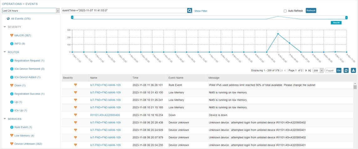

Viewing Events

This section provides information on the events generated on FAR and HER when pushing and removing PSK tunnel configuration.

Viewing FAR Events

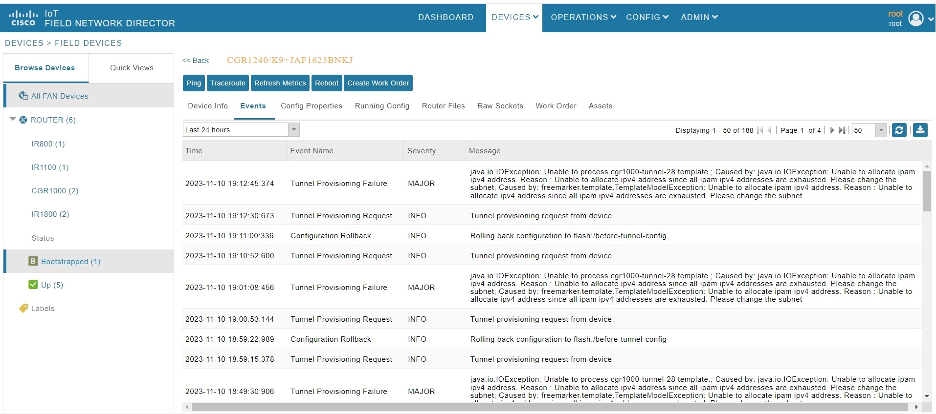
Use the following steps to view the events generated when pushing PSK tunnel configuration on HER during FAR onboarding.

  1. Choose DEVICES > FIELD DEVICES.

  2. Select the device on the right pane. The Device Info page appears.

  3. Click the Events tab to view the following events.

    Event Name

    Severity Level

    Description

    PSK Tunnel Configuration Pushed to HER

    INFO

    On successful completion of pushing PSK tunnel configuration on HER.

    PSK Tunnel Configuration on HER Failed

    Major

    On failure to push the PSK tunnel configuration on HER.

Viewing HER Events

Use the following steps to view the events generated when removing the PSK tunnel configuration from HER and FAR during FAR decommissioning.

  1. Choose DEVICES > HEAD-END ROUTERS.

  2. Select the HER on the right pane. The Device Info page appears.

  3. Click the Events tab to view the following events.

    Event Name

    Severity Level

    Description

    HER PSK Tunnel Configuration Removed for FAR

    INFO

    On successful removal of PSK configuration from HER.

    HER PSK Tunnel Configuration Removal Failure for FAR

    Major

    On failure to remove the PSK configuration from HER.

    Note


    In this case, you should remove the PSK configuration from HER manually.

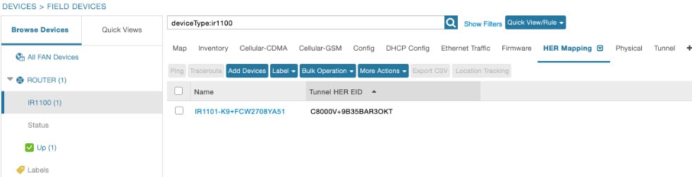
HER Mapping with FAR

Use the following steps to view the HERs associated with the FAR.

  1. Choose DEVICES > FIELD DEVICES.

  2. Select the device on the left pane.

  3. Click the HER Mapping tab on the right pane.

  4. The HER associated with the device appears under the Tunnel HER EID column.

    Use the filter option to search for HERs based on HER EID.

Decommissioning a Device

Whenever there is a device decommissioning, FND automatically removes the PSK configuration from HER using the HER deletion template which is available by default. If the HER is in a cluster, FND removes the PSK configuration from all HERs.

For information on HER deletion template, see HER tunnel deletion template.

For information on events generated during PSK configuration removal from HER, see Viewing HER Events.

List of Ports used in Simplified IoT FND Architecture for Router only Deployments

The table provides the list of standard ports used in simplified IoT FND architecture.

Service

Port

GUI

443

Tunnel Provisioning

9120

TPS

9122

PostGreSql DB Server

5432

Influx

8086

Kapacitor

9092

WSMA (for IOS-XE)

443

WSMA (for Classic IOS)

8443

Registration + Periodic

9121

Bandwidth Op Mode

9124

PnP — HTTP

9125

Web Sockets — Device Communication

9121

DB Replication for HA

1622

SSH

22

NTP Server

123

SNMP (for polling)

161

SNMP (for notifications)

162

SSM Server

8445

FND Demo Mode

80

Syslog service

514

PSK Challenge String Support

The pre-shared key challenge string is supported to enhance the security between FND and FAR in the SUDI+PSK based tunnel management. In this process, FND generates the challenge string during its first communication with the device. The generated nonce is pushed to the device and signed using the SUDI certificate. The signed response is validated against the SUDI certificate and the hash of the nonce is verified against the nonce sent by FND. The nonce is verified only for the first time when a device communicates with FND.

Only Cisco IOS-XE devices support the challenge string using the SUDI certificate.


Note


By default, the challenge string validation is enabled for PSK-based tunnels. However, you can skip the device validation using the challenge string by setting the cgms.properties to false. After disabling the property, you have to restart the cgms service.

enable-challenge-string-auth=false

Device Validation Using a Challenge String

FND validates the device during onboarding by sending a challenge string using the following command.

sh platform sudi certificate sign nonce <generated number>
  • On successful verification, FND authenticates the device for further communications.

  • If the verification fails, an error message is logged in the server.log file, and the device is not onboarded.

PSK Rotation

To protect against pre-shared key (PSK) vulnerabilities and hacks, PSK rotation is utilized in Cisco IoT FND, which provides an additional layer of security for the device communication. This involves running the script either manually or schedule using a cron. The script is bundled with the cgms tools package of Cisco IoT FND. The cgms tools package is installed on a Cisco IoT FND Postgres VM. However, you can also install the cgms tools package on a separate VM (It is not necessary to have Cisco IoT FND installed in this VM). For information on installing cgms tools on a separate VM, see Installing CGMS Tools RPM on a Separate VM.

When the script is run, it rotates the pre-shared key at both HER and FAR and flaps the tunnels for a secure network. The PSK rotation feature is available only to customers who use PSK for tunnel management with FlexVPN.

Prerequisites

Ensure that all prerequisites are met before running the PSK rotation script for every fresh install or upgrade.

  • Run the script during the maintenance window.

  • Ensure that the Cisco IoT FND service is not active when executing the script.

  • Ensure that there are no active operations (like configuration push, firmware upgrade) running in Cisco IoT FND.

  • Copy the following files from cgms rpm package (/opt/cgms) to cgms-tools package (/opt/cgms-tools).

    Filename

    Copy From (cgms package)

    Copy To (cgms-tools package)

    fnd_psk_enc

    /opt/cgms/server/cgms/conf/.fnd_psk_enc

    /opt/cgms-tools/conf

    fnd_psk.keystore

    /opt/cgms/server/cgms/conf/fnd_keystore

    /opt/cgms-tools/conf

    jdbc.properties

    /opt/cgms/tools/conf/jdbc.properties

    /opt/cgms-tools/conf/jdbc.properties

    cgms_keystore

    /opt/cgms/server/cgms/conf/cgms_keystore

    /opt/cgms-tools/conf

    cgms.properties

    /opt/cgms/server/cgms/conf/cgms.properties

    /opt/cgms-tools/conf

Manual PSK Rotation

Run the following script (location: /opt/cgms-tools/bin) to rotate the PSK.

$ ./rotate-psk <csv-file>

The <csv-file> refers to the CSV file location, which contains the list of HER name or FAR name (with HER peer name).

  • If the CSV file contains the name of the HER, then the HER PSK of all the FARs and the FAR PSK are rotated.

  • If the CSV file contains the name of the FAR, then the PSK of the specified FAR and the HER associated with the FAR are rotated.

Sample CSV file with HER NAME:

HER_NAME, HER_PEER_NAME, KEYRING_NAME, DOMAIN_NAME
C8000V+9B35BAR3OKT, CLUSTER-2, FlexVPN_Keyring, cisco.com
C8000V+9OA9SRYYZVZ, CLUSTER-1, FlexVPN_Keyring1, cisco.com

Note


HER_PEER_NAME is the identity local key-id name configured on the HER.


Sample CSV file with FAR NAME:

FAR_NAME, HER_PEER_NAME , KEYRING_NAME, DOMAIN_NAME
IR1835-K9+FCW2730Y1UZ, CLUSTER-1, FlexVPN_Keyring, cisco.com
IR1101-K9+FCW2710ZA25, CLUSTER-2, FlexVPN_Keyring1, cisco.com
IR1101-K9+FCW2708YA53, CLUSTER-2, FlexVPN_Keyring2, cisco.com

The status of the device PSK rotation, for both success or a failure, is available in the CSV file (rotate-psk-timestamp.csv).

Log Location:

  • The output status log of PSK rotation for each device is stored at: /opt/cgms-tools/log/rotate-psk-<timestamp>.csv.

    Sample CSV output:
    ROUTER,MESSAGE,STATUS
    IR1835-K9+FCW2730Y1UZ,PSK update for FAR IR1835-K9+FCW2730Y1UZ was failure as FAR is down ,FAILURE
    IR1835-K9+FCW2730Y2UZ,PSK update success for FAR IR1835-K9+FCW2730Y1UZ connected to HER C8000V+9B35BAR3OKT,SUCCESS
  • Debug logs are stored at: /opt/cgms-tools/log/rotate-psk.log.

Schedule PSK Rotation Using Cron

Alternatively, cron is used to run the script automatically at a specific time and day of a month. You can schedule PSK rotation for the following deployments:

The following prerequisites are must:

  • Ensure that the script is scheduled to run during the monthly maintenance window to avoid conflict with other active operations in Cisco IoT FND.

  • For a successful PSK rotation, it is recommended to allow a 24-hour gap between each script execution.


Note


After each successful PSK rotation, the tunnel is toggled. As a result, the tunnel between HER and FAR comes up with a new PSK value.


Postgres OVA Deployment

Follow the steps to schedule PSK rotation for Postgres OVA.

Procedure


Step 1

Install the tools rpm in VM.

Step 2

Enable the db connection in pg_hba.conf with the following entry.

host all all <IP of the VM to be entered here>/32 md5

Step 3

Restart postgresql.

service postgresql-12 stop
 service postgresql-12 start
 

Step 4

Copy the following files from docker container to cgms-tools package.

  1. docker cp fnd-container:/opt/cgms/server/cgms/conf/.fnd_psk_enc /opt/cgms-tools/conf

  2. docker cp fnd-container:/opt/cgms/server/cgms/conf/fnd_psk.keystore /opt/cgms-tools/conf

  3. docker cp fnd-container:/opt/cgms/tools/conf/jdbc.properties /opt/cgms-tools/conf/jdbc.properties

  4. docker cp fnd-container:/opt/cgms/server/cgms/conf/cgms_keystore /opt/cgms-tools/conf

  5. docker cp fnd-container:/opt/cgms/server/cgms/conf/cgms.properties /opt/cgms-tools/conf


Installing CGMS Tools RPM on a Separate VM

Follow the steps to install CGMS tools rpm on a separate VM.

Procedure


Step 1

Install the cgms-tools rpm.

  • For the Postgres deployment, extract the cgms tools file (CISCO-IOTFND-VPI-K9-CGMS-TOOLS-<release>-<build>.zip) from the upgrade script (CISCO-IOTFND-VPI-K9-UPGRADE-SCRIPTS-<release>-<build number>.zip) and install the cgms tools in the server. For more information, see Postgres Installation Guide.

Step 2

Copy the prerequisite files from the Cisco IoT FND server to the path where the cgms-tools package is installed.

  • copy .fnd_psk_enc from /opt/cgms/server/cgms/conf/.fnd_psk_enc to /opt/cgms-tools/conf
    
  • copy fnd_psk.keystore from /opt/cgms/server/cgms/conf/fnd_psk.keystore to /opt/cgms-tools/conf
    
  • copy jdbc.properties from /opt/cgms/tools/conf/jdbc.properties to /opt/cgms-tools/conf/jdbc.properties
    
  • copy cgms_keystore from /opt/cgms/server/cgms/conf/cgms_keystore to /opt/cgms-tools/conf
    
  • copy cgms.properties from /opt/cgms/server/cgms/conf/cgms.properties to /opt/cgms-tools/conf 

Step 3

Provide Postgres IP in the jdbc.properties as below.

jdbc.url=jdbc:postgresql://<Postgres IP>:5432/cgms

Step 4

Add the route in the server for the device reachability.

On successful cgms tools installation, the PSK rotation script is executed.


IPAM for Loopback

Loopback IP addresses for FAR devices forming tunnels was assigned by an external DHCP Server with FND acting as the DHCP client. IoT FND now generates the IPv4 and IPv6 addresses for the provided subnet while forming the tunnels without relying on the third-party DHCP Server. The consumption of internal IP addresses applies only for first-time IoT FND installation and the users with administrative privileges only can access. This is supported only in root domain.

Procedure


Step 1

While setting up IoT FND, run the setupCgms.sh script on the IoT FND server and choose your preferred IP allocation method for loopback IPs in the user prompt. For more information about running the setupCgms.sh script, see Setting Up IoT FND.

Step 2

If you choose IPAM, configure the subnet in the Admin > System Management > Provisioning Settings page.

Note


To configure the subnet range, set the limit in ipam-ipv6-subnet-limit or ipam-ipv4-subnet-limit property in cgms.properties file. The default values for the properties are 108 (generates around 1,048,576 IPv6) and 12 (generates around 1,048,576 IPv4) respectively.

Caution


Do not decrease the subnet size. If you intend to utilize more than 1 million IP addresses, we recommend consulting with Cisco for expert guidance and support.

Step 3

Provide the exclusion range as a single IP address, a range, or a list of multiple IP addresses separated by commas. The Usage Statistics is a label that shows the IP addresses utilized for the provided subnet.

Note


Provide values in either or both of the IPAM IPv6 and IPAM IPv4 setting.

Step 4

Click the Disk icon to save changes. The following window pops up to show the probable IP addresses that will be generated.

Note


If you choose to modify the subnet after the warning, then IoT FND deletes all the existing ip addresses created under previous subnet except the one being used and generates fresh ip addreses for new subnet.

Step 5

Click Yes.

Step 6

Navigate to ADMIN > SYSTEM MANAGEMENT > AUDIT TRAIL page to check for the number of excluded IPs and the generated usable IPs.

After configuring subnet settings and generating IP addresses, initiate the tunnel provisioning process.

Note


During tunnel provisioning, if the IP address is provided in the CSV in the loopbackv4address and loopbackv6address property when adding routers, it is utilized as the loopback IP address. In case the IP address is not provided in the CSV, then internal IP address is fetched.

If the tunnel provisioning fails as IP address lease exceeds, then the error message is seen in the DEVICES > FIELD DEVICES page under Events tab.

Note


In the Operations > Events page, check the event generated. A minor event is generated if the percentage of utilization crosses 80% of total generated IP. Similarly, a major event is generated if the percentage of utilization crosses 90% of total generated IP. You can configure the limit for major threshold in ipam-ipAddress-pool-thresold-limit property in cgms.properties file. The default value is set to 90, if not configured.

Once tunnels are assigned an IP address, the DB is also updated.

For tunnel reprovisioning, the router uses the same IP address.


IPAM for All Interfaces

The IP addresses for FAR devices forming tunnels was assigned by an external DHCP server with IoT FND acting as the DHCP client. IoT FND now generates the IPv4 and IPv6 addresses for the provided subnet while forming the tunnels without relying on the third-party DHCP server. The consumption of internal IP addresses applies only for first-time IoT FND installation and the users with administrative privileges only can access. This is supported only in root domain.

Starting from IoT FND release 4:12 onwards, IoT FND supports IPAM for all interfaces. You can define multiple subnets and IoT FND manages those subnets.


Note


When you upgrade to IoT FND release 4:12, one subnet is migrated, subnet id is created and listed under the respective tabs in the Provisioning settings page.


Procedure


Step 1

To enable IPAM, run the setupCgms.sh script on the IoT FND server while setting up IoT FND. Choose IPAM in the user prompt. IPAM takes precedence over DHCP server for IP address management. For more information about running the setupCgms.sh script, see Setting Up IoT FND.

Step 2

If you choose IPAM, configure the subnet in the Admin > System Management > Provisioning Settings page.

Step 3

Click the IPAM-IPv4 and IPAM-IPv6 tabs to define the IPv4 and IPv6 subnets.

Note


To configure the subnet range, set the limit in ipam-ipv6-subnet-limit or ipam-ipv4-subnet-limit property in cgms.properties file. The default values for IPv6 and IPv4 properties are 108 (generates around 1,048,576 IPv6) and 12 (generates around 1,048,576 IPv4) respectively.

Caution


Do not decrease the subnet size. If you intend to utilize more than 1 million IP addresses, we recommend consulting with Cisco for expert guidance and support.

Step 4

Enter the Subnet Address and Exclusion range. The Exclusion range can be provided as a single IP address, range, or list of multiple IP addresses separated by commas.

Note


You cannot define more than 10 subnets. The following error message appears when you try to define additional subnets. This is applicable for IPv6 subnets as well.

Step 5

Click the Disk icon to save changes. The following window pops up to show the probable IP addresses that will be generated.

Step 6

Click Yes. The IP address generation is in progress.

The following table describes the fields in the IPv4 Subnets tab.

Field

Description

Id

Indicates the subnet id allocated for the defined subnet.

Subnet Address

Indicates the defined subnet address.

Exclusion range

Indicates the range of IP addresses within a subnet that are excluded from being assigned to devices.

Usage Statistics

Indicates the IP addresses utilized for the provided subnet.

Actions

You can either modify or delete the subnets.

Step 7

To edit the subnet details:

  • Click Edit to modify the subnet.

  • Edit the Subnet Address and Exclusion range and click Modify.

    Important


    You can only extend the subnet while editing and shrinking the subnet is not allowed.

You can also delete the subnet by clicking the delete icon. In case you delete the subnet where some of the IPs are utilized, the following warning pops up. Click Yes to proceed.

Note


It is recommended to recheck before proceeding as there are no restrictions in deletion.

Step 8

Navigate to ADMIN > SYSTEM MANAGEMENT > AUDIT TRAIL page to see the addition, modification, and deletion of the subnets.

Step 9

Go to CONFIG > TUNNEL PROVISIONING and click Router Tunnel Addition. Enter the Subnet ID in the Router Tunnel Addition template and click Save.

interface Loopback0
    <#--
      If the loopback interface IPv4 address property has been set on the CGR
      then configure the interface with that address. Otherwise obtain an
      address for the interface now using DHCP.
    -->
    <#if far.loopbackV4Address??>
      <#assign loopbackIpv4Address=far.loopbackV4Address>
    <#elseif far.isIPAMSelected()??>
      <#assign loopbackIpv4Address=far.IPAMIpv4address(1)>
    <#else>
      <#--
        Obtain an IPv4 address that can be used to for this FAR's Loopback
        interface. The template API provides methods for requesting a lease from
        a DHCP server. The IPv4 address method requires a DHCP client ID and a link
        address to send in the DHCP request. The 3rd parameter is optional and
        defaults to "IoT-FND". This value is sent in the DHCP user class option.
        The API also provides the method "dhcpClientId". This method takes a DHCPv6
        Identity association identifier (IAID) and a DHCP Unique IDentifier (DUID)
        and generates a DHCPv4 client identifier as specified in RFC 4361. This
        provides some consistency in how network elements are identified by the
        DHCP server.
      -->
      <#assign loopbackIpv4Address=far.ipv4Address(dhcpClientId(far.enDuid,0),far.dhcpV4LoopbackLink).address>
    </#if>
    ip address ${loopbackIpv4Address} 255.255.255.255
    <#--
      If the loopback interface IPv6 address property has been set on the CGR
      then configure the interface with that address. Otherwise obtain an
      address for the interface now using DHCP.
    -->
    <#if far.loopbackV6Address??>
      <#assign loopbackIpv6Address=far.loopbackV6Address>
    <#elseif far.isIPAMSelected()??>
      <#assign loopbackIpv6Address=far.IPAMIpv6address(21)>
    <#else>

Note


IoT FND throws the following error while processing the template during tunnel provisioning if the template contains obsolete methods.

Step 10

After configuring subnet settings and generating IP addresses, initiate the tunnel provisioning process. Once the PNP is complete, the IP addresses are allocated to the respective interfaces which can be seen under the IPv4 and IPv6 tabs in the Admin > System Management > Provisioning Settings page.

Note


During tunnel provisioning, if the IP address is defined in the CSV in loopbackv4address and loopbackv6address property while adding routers, it is utilized as the loopback IP address. In case the IP address is not provided in the CSV, then internal IP address is fetched. This is applicable for loopback interface only.

Step 11

In the Operations > Events page, an event is generated if the percentage of utilization crosses 90% of total generated IP.You can configure the limit for major threshold in ipam-ipAddress-pool-thresold-limit property in cgms.properties file. The default value is set to 90, if not configured.

Once tunnels are assigned an IP address, the DB is also updated.

During decommissioning of the device or subnet, IPAM IP address is marked unused. Click Refresh and the IP addresses is released.