Cisco NCS 1014 Chassis Overview
The Cisco NCS 1014 chassis is an advanced multihaul optical platform supporting transponders and line system cards. It is a 2RU chassis that delivers a universal transponder solution which provides excellent performance for metro, long-haul, and submarine applications.
Cisco NCS 1014 chassis has slots for the following modules:
-
Removable controller
-
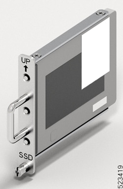
Removable backup solid state drive (SSD)
-
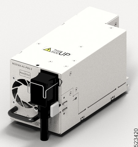
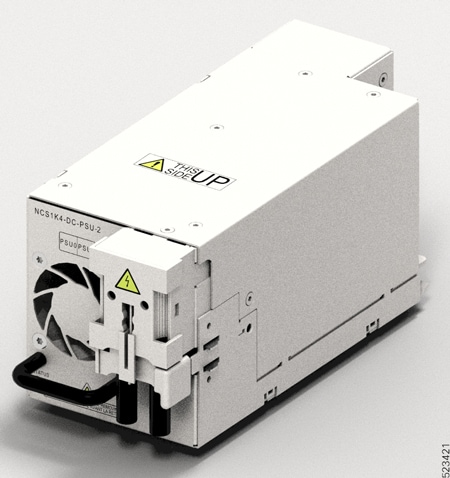
Two replaceable power supply units (PSU)
-
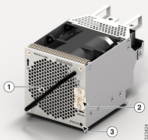
Three replaceable fan modules
-
Four line cards
The Cisco NCS 1014 chassis supports the line cards.
|
Line Card |
Description |
Release |
|---|---|---|
|
2.4T DWDM Transponder Card |
Cisco IOS XR Release 7.11.1 |
|
|
16-port Colorless Mux/Demux Card, C-band |
Cisco IOS XR Release 7.11.1 |
|
|
16-port Colorless Mux/Demux Card, L-band |
Cisco IOS XR Release 7.11.1 |
|
|
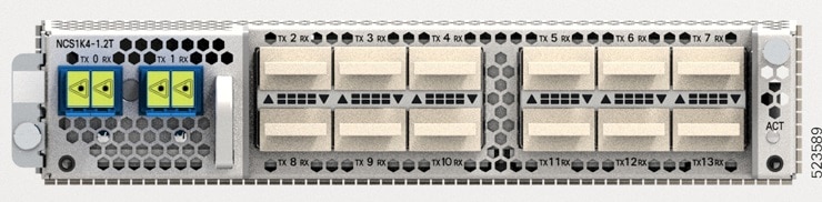
1.2T DWDM Transponder Card |
Cisco IOS XR Release 7.11.1 |
|
|
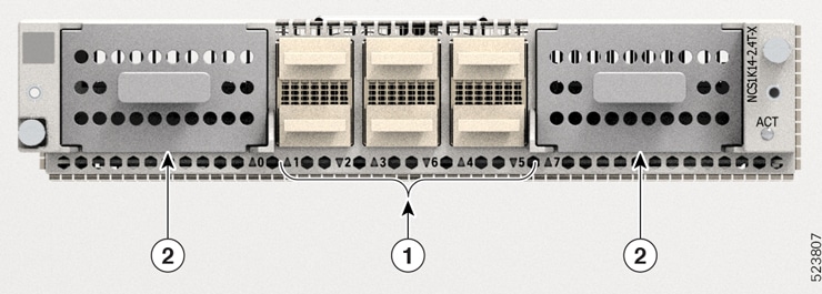
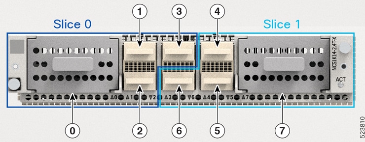
2.4TX DWDM Transponder Card |
Cisco IOS XR Release 24.1.1 |
|
|
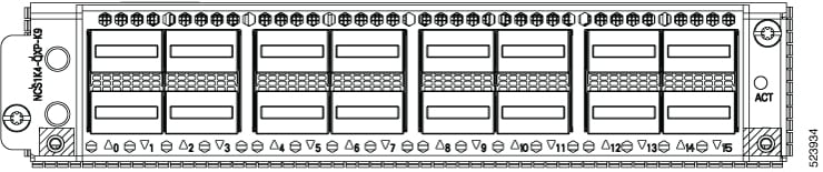
3.2T DWDM Transponder Card |
Cisco IOS XR Release 24.1.1 |
|
|
1.2T DWDM Transponder Card - Licensed |
Cisco IOS XR Release 24.4.1 |
|
|
EDFA Terminal with Equalization Card |
Cisco IOS XR Release 25.1.1 |
|
|
2-QDD-C DWDM line card |
Cisco IOS XR Release 25.2.1 |
The Cisco NCS 1014 chassis supports the following line cards.
|
Passive Devices |
Description |
Release |
|---|---|---|
|
32-channel Odd Mux/Demux Patch Panel, C-band Enhanced |
Cisco IOS XR Release 25.1.1 |
|
|
32-channel Even Mux/Demux Patch Panel, C-band Enhanced |
Cisco IOS XR Release 25.1.1 |
The Cisco NCS 1014 chassis has two slots for field-replaceable AC and DC PSUs that support up to 2.5 kW per system and 580 W per line card slot.
For more information about the Cisco NCS 1014 chassis, see Cisco NCS 1014 datasheet.
 Note |
|
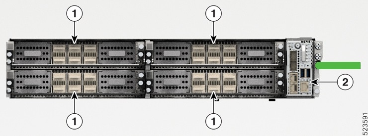
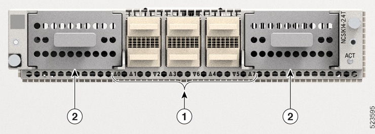
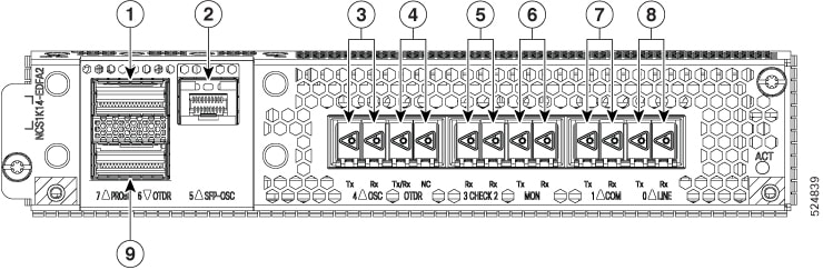
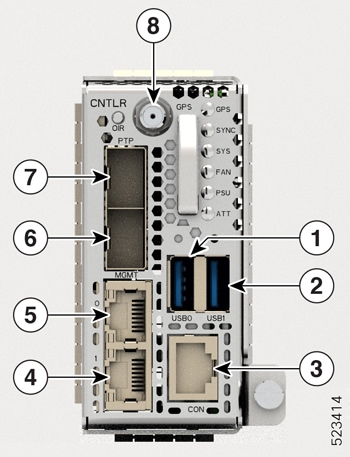
The controller is on the front side. The SSD, PSUs, and the fan modules are on the rear side of the chassis. You can insert the line cards into the four slots as shown in the following figure.
|
Callout |
Modules |
|---|---|
|
1 |
Line Cards |
|
2 |
Controller |
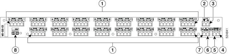
The following figure shows the PSUs, fan modules, and SSD installed in the chassis.
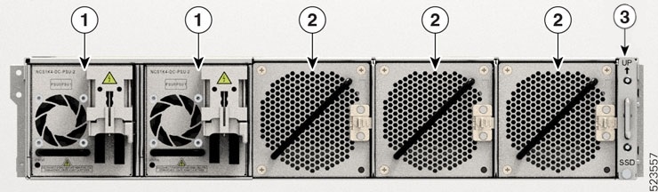
|
Callout |
Modules |
|---|---|
|
1 |
Power Supply Units (Slots 0 and 1) |
|
2 |
Fan Modules (Slots 0, 1, and 2) |
|
3 |
SSD |
You must install AC or DC PSUs as the power supply modules. The chassis does not allow mixed PSU configuration.
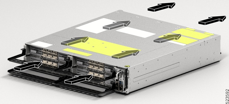
Airflow in the Cisco NCS 1014 Chassis
The Cisco NCS 1014 chassis has a front-to-back airflow scheme. The air inlet is at the front side of the chassis and the exhaust is on the rear side. The fan modules cool down the line cards. Ensure that no object obstructs or impedes the airflow as it can lead to reduced airflow in the system, causing components to operate at a higher temperature.
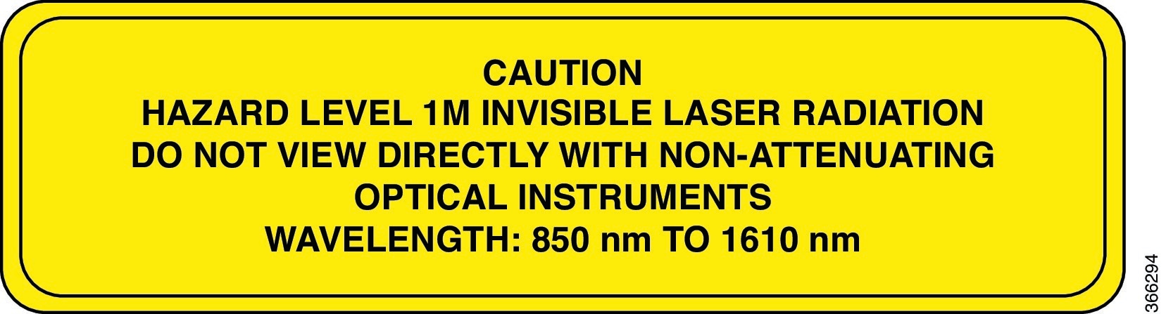
Class 1M Laser Product Label
The Class 1M Laser Product label is shown in the following figure.
Cooling System
The Cisco NCS 1014 cooling system actively regulates the chassis temperature using the three field-replaceable fan trays and the built-in fans within the PSU units. This system implements cooling in two different airflow paths:
-
Line Cards Cooling
The three fan modules enable cooling for the line cards. The software monitors the chassis temperature and adjusts the fan speed according to the ambient temperature range.
-
Controller Card Cooling
The internal fans within the two PSUs cool the controller card. If any critical alarms arise due to controller temperature, the software overrides the PSU fan speed.
Note
For normal operating conditions, the software does not control the PSU fans.
During the power cycle, each fan runs at maximum rotations per minute. After the chassis boots up, the fans return to their normal speed according to the ambient temperature.
Cooling profiles of the NCS 1014 chassis
Beginning with Release 25.2.1, the NCS 1014 chassis supports the programmable NCS1K14-FAN-P fan module, which runs two cooling profiles. The programmable fan changes its cooling profile depending on the installed line cards and pluggable modules. By default, the programmable fan uses the low-power, low-cooling profile.
Cooling profiles work only when you fill all fan slots with programmable fan modules.
The cooling profiles of the fans change based on the status of the NCS 1014 chassis. During controller Online Insertion and Removal (OIR), line card OIR, fan OIR, or fan failure, the fans run at maximum cooling profile speed.
Note |
During the INFRA POWER CYCLE, the system runs the fans at maximum speed for the low-cooling profile. Therefore, perform the INFRA POWER CYCLE only when the ambient temperature is less than or equal to 40°C. Perform line card or fan OIR, line card or fan replacement, or any software or FPD upgrade only at an inlet temperature less than or equal to 40°C. Use show environment0/Rack to check inlet temperature. |
Legacy fans support a static cooling profile, while programmable fans support a dynamic cooling profile. The NCS 1014 offers three profiles: low cooling, high cooling, and legacy cooling. The inlet temperature sensors, SA_TEMP_CHASSIS_INLET0 and SA_TEMP_CHASSIS_INLET1, determine when to increase or decrease fan speed. For more information on fan RPM for each cooling profile, refer Fan modules.
Programmable fans installed in pre-Release 25.2.1
If you install the programmable fans in a release earlier than 25.2.1, where they are not supported, the fan units do not appear in the show inventory output. The system raises the Fan tray absent alarm even though the fans continue to run in the chassis. It is recommended not to install the programmable fan units in the chassis running earlier releases.
Mixed fan configuration
A mixed fan configuration involves installing both legacy and programmable fan units together.
If both legacy and programmable fans are installed in the NCS 1014 fan slots during live traffic or card configuration, the system raises the CONFIG MISMATCH alarm. To clear the alarm, equip the fan slots with either the legacy or programmable fans. The mixed fan configuration is allowed only for a limited time during a fan upgrade. In this configuration, the legacy fan runs at 14,500 rpm and the programmable fan runs at 17,000 rpm.
Programmable fan speed implementation on NCS 1014 line cards
|
Feature Name |
Release Description |
Feature Description |
|---|---|---|
|
NCS1K14-FAN-P Enhanced Fan Profile Support |
Cisco IOS XR Release 25.2.1 |
The NCS1K14-FAN-P provides enhanced fan profile management for the NCS 1014 platform, enabling improved power efficiency and flexibility for various use cases. The system automatically adjusts the fan profile based on the line cards inserted in the chassis. For example,
This dynamic fan profile enables optimal power consumption for Metro Open Line System (MOLS) 2.0 and NCS1K14-CCMD-16-x configurations. |
Fan cooling profiles provide appropriate cooling for the NCS 1014 chassis based on the installed line cards. This dynamic cooling profile enables optimal power consumption for MOLS 2.0 and NCS1K14-CCMD-16-x configurations.
| The fans maintain |
For configuration on |
|---|---|
|
low-cooling profile |
MOL2.0, optical and OLS line cards.
|
|
high-cooling profile |
transponders line cards.
|
Programmable fan speed implementation on NCS 1014 for coherent pluggables
|
Feature Name |
Release Description |
Feature Description |
|---|---|---|
|
NCS1K14-FAN-P Smart Fan Implementation for Pluggable modules |
Cisco IOS XR Release 25.2.1 |
The NCS1K14-FAN-P enhanced fan profile support is extended to pluggable modules on the transponder line cards.
|
The enhanced fan cooling profiles also apply to pluggable modules on the transponder line cards.
|
smart fan speed works for |
in line cards |
|---|---|
|
CIM8 C- and L-band pluggable modules
|
NCS1K14-2.4T-K9 and NCS1K14-2.4T-X-K9 |
|
Bright ZRP pluggable module with regen (regeneration) and without regen configurations
|
NCS1K4-QXP-K9 |


 Feedback