Cisco Nexus 93120TX NX-OS Mode Switch Hardware Installation Guide
偏向のない言語
この製品のマニュアルセットは、偏向のない言語を使用するように配慮されています。このマニュアルセットでの偏向のない言語とは、年齢、障害、性別、人種的アイデンティティ、民族的アイデンティティ、性的指向、社会経済的地位、およびインターセクショナリティに基づく差別を意味しない言語として定義されています。製品ソフトウェアのユーザーインターフェイスにハードコードされている言語、RFP のドキュメントに基づいて使用されている言語、または参照されているサードパーティ製品で使用されている言語によりドキュメントに例外が存在する場合があります。シスコのインクルーシブランゲージに対する取り組みの詳細は、こちらをご覧ください。
翻訳について
このドキュメントは、米国シスコ発行ドキュメントの参考和訳です。リンク情報につきましては、日本語版掲載時点で、英語版にアップデートがあり、リンク先のページが移動/変更されている場合がありますことをご了承ください。あくまでも参考和訳となりますので、正式な内容については米国サイトのドキュメントを参照ください。
- Updated:
- 2017年6月22日
章のタイトル: Overview
Overview
The Cisco Nexus 93120TX switch (N9K-C93120TX) is a 2-RU, fixed-port switch designed for Top-of-Rack (ToR), Middle-of-Rack (MoR), and End-of-Rack (EoR) deployment in data centers. This switch has 96 fixed 1/10GBASE-T (copper) downlink ports and six fixed 40-Gigabit QSFP+ (optical) uplink ports. The chassis for this switch includes the following user-replaceable components:
-
Fan modules (two) with the following airflow choices:
-
Power supply modules (two—one for operations and one for redundancy [1+1]) with the following choices:
-
1200-W AC power supply with port-side intake airflow (burgundy coloring) (N9K-PAC-1200W)
-
1200-W AC power supply with port-side exhaust airflow (blue coloring) (N9K-PAC-1200W-B)
-
1200-W HVAC/HVDC power supply with dual-direction airflow (white coloring) (N9K-PUV-1200W)
-
930-W DC power supply with port-side intake airflow (green coloring) (UCSC-PSU-930WDC)
-
930-W DC power supply with port-side exhaust airflow (gray coloring) (UCS-PSU-6332-DC)

(注)
Both power supplies should be the same type. Do not mix AC, DC, or HVAC/HVDC power supplies.
(注)
All fan modules and power supplies must use the same airflow direction during operations. If you are using the 1200-W HVAC/HVDC power supply, the power supply automatically uses the same airflow direction as used by the other modules in the switch.
-
The following figure shows the hardware features seen from the port side of the chassis.
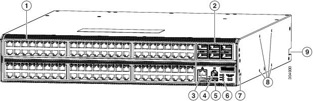
| 1 |
96 10GBASE-T copper ports (supporting speeds of 100 Megabits, 1 Gigabit, and 10 Gigabits) to other devices |
6 |
Chassis LEDs |
||
| 2 |
6 40-Gigabit Ethernet Quad Small Form-Factor Plugable (QSFP+) optical ports for uplink connections to aggregation switches |
7 |
Screw holes (2) for attaching a front-mount bracket for 4-post racks (1 bracket on each of 2 sides) |
||
| 3 |
Out-of-band management port (RJ-45 port) |
8 |
Screw holes (4) for attaching a center-mount rack bracket for two-post racks (1 bracket for each of 2 sides) |
||
| 4 |
Console port (RS232 port) |
9 |
Notch in both sides of the chassis for locking the power supply end of the chassis to the bottom-support rails |
||
| 5 |
2 USB ports used for saving or copying functions
|
To determine which transceivers, adapters, and cables are supported by this switch, see the Cisco Transceiver Modules Compatibility Information document.
The following figure shows the hardware features seen from the power supply side of the chassis.
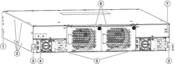
| 1 |
Screw holes (2) for attaching a front-mount bracket for 4-post racks (1 bracket on each of 2 sides). |
5 |
2 power supplies (1 used for operations and 1 used for redundancy) (AC power supplies shown) with power supply slot 1 on the left and slot 2 on the right. |
| 2 |
Screw holes (4) for attaching a center-mount rack bracket for 2-post racks (1 bracket for each of 2 sides). |
6 |
2 fan modules with fan slot 1 on the left and fan slot 2 on the right. |
| 3 |
A notch in both sides of the chassis for locking the fan side of the chassis to the bottom-support rails. |
7 |
Chassis LEDs include the following: |
| 4 |
Screw holes (2) for attaching the grounding lug to both sides of the chassis. |
Depending on whether you plan to position the ports in a hot or cold aisle, you can order the fan and power supply modules with port-side intake or port-side exhaust airflow. For port-side intake airflow, the fan and AC power supply modules have burgundy coloring (DC power supply modules have green coloring). For port-side exhaust airflow, the fan and AC power supplies have blue coloring (DC power supply modules have gray coloring). You can also order the 1200-W HVAC/HVDC power supply which has dual-direction airflow with white coloring. Dual-direction airflow modules automatically use the airflow direction of the other modules installed in the switch.
The fan and power supply modules are field replaceable and you can replace one fan module or one power supply module during operations so long as the other modules are installed and operating. If you have only one power supply installed, you can install the replacement power supply in the open slot before removing the original power supply.
(注) |
All of the fan and power supply modules must have the same direction of airflow. Otherwise, the switch can overheat and shut down. If you are installing a dual-direction power supply, that module will automatically use the same airflow direction as the other modules in the switch. |
 注意 |
If the switch has port-side intake airflow (burgundy coloring for fan modules), you must locate the ports in the cold aisle. If the switch has port-side exhaust airflow (blue coloring for fan modules), you must locate the ports in the hot aisle. If you locate the air intake in a hot aisle, the switch can overheat and shut down. |
 フィードバック