Cisco Nexus 93120TX NX-OS Mode Switch Hardware Installation Guide
偏向のない言語
この製品のマニュアルセットは、偏向のない言語を使用するように配慮されています。このマニュアルセットでの偏向のない言語とは、年齢、障害、性別、人種的アイデンティティ、民族的アイデンティティ、性的指向、社会経済的地位、およびインターセクショナリティに基づく差別を意味しない言語として定義されています。製品ソフトウェアのユーザーインターフェイスにハードコードされている言語、RFP のドキュメントに基づいて使用されている言語、または参照されているサードパーティ製品で使用されている言語によりドキュメントに例外が存在する場合があります。シスコのインクルーシブランゲージに対する取り組みの詳細は、こちらをご覧ください。
翻訳について
このドキュメントは、米国シスコ発行ドキュメントの参考和訳です。リンク情報につきましては、日本語版掲載時点で、英語版にアップデートがあり、リンク先のページが移動/変更されている場合がありますことをご了承ください。あくまでも参考和訳となりますので、正式な内容については米国サイトのドキュメントを参照ください。
- Updated:
- 2017年6月22日
章のタイトル: Replacing Modules
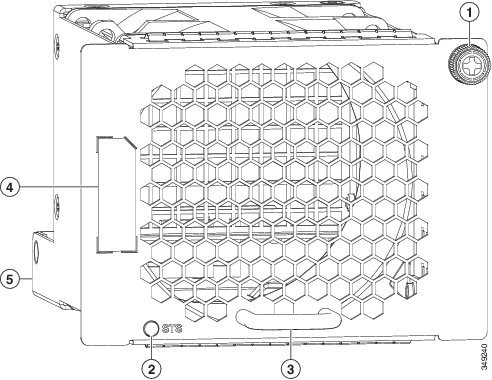
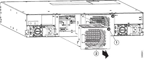
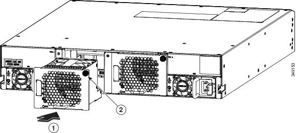
Replacing a Fan Module During Operations
There must always be at least two fan modules installed in the chassis to maintain the designed airflow. You can remove one fan module temporarily to replace it with another fan module but if the replacement fan module is not available, leave the original fan module in the chassis.
All fan and power supply modules must have the same airflow direction or else an error can occur with the switch overheating and shutting down. You can determine the airflow direction of a fan module by the color of the stripe on the front of the module. If the fan module has a blue stripe for port-side exhaust airflow, the power supplies must have blue or gray coloring for the same airflow direction. If the fan module has a burgundy stripe for port-side intake airflow, the power supplies must have burgundy or green coloring for the same airflow direction. If a power supply has white coloring, it can be used with fan modules using either port-side intake or port-side exhaust airflow. To avoid over heating the switch, make sure that the fan modules are positioned in one of the following ways:
Before you can replace a fan module, ensure that both of the following conditions exist:
-
There is another functioning fan module in the chassis. In order to replace a fan module during operations, there must be another fan module circulating air in the chassis at all times.
-
The replacement fan module must have the same airflow direction as the other modules in the chassis.
If you must replace the fan module during operations and both of the above conditions are not met, leave the fan module that you need to replace in the chassis to preserve the designed airflow until you have the required module.
Replacing a Power Supply Module
The switch requires two power supplies for redundancy. With one power supply providing the necessary power for operations, you can replace the other power supply during operations so long as the new power supply has the same airflow direction as the other modules in the chassis.
 (注) |
If you need to change the airflow direction of the switch modules, you must shut down the switch before changing all of the modules to modules using the other airflow direction. |
You can replace a power supply with any other power supply that is supported by the same switch so long as it provides the same direction of airflow as the fan modules installed in the switch and uses the same type of power source as the other power supply installed in the switch (do not mix AC, DC, and HVAC/HVDC power supplies in the same switch). The coloring of the latch handle on the power supply indicates the airflow direction as explained in the following table that lists the supported power supplies for this switch.
| Part Number |
Power Characteristics |
Airflow Direction (Latch Color) |
|---|---|---|
| N9K-PAC-1200W |
1200 W, 16 A, AC power source |
Port-side intake (burgundy latch) |
| N9K-PAC-1200W-B |
1200 W, 16 A, AC power source |
Port-side exhaust (blue latch) |
| N9K-PUV-1200W |
1200 W, 16 A, HVAC/HVDC power source |
Dual direction (white latch) (These modules automatically use the same airflow direction as the fan modules installed in the same switch.) |
| UCSC-PSU-930WDC |
930 W, 16 A, DC power source |
Port-side intake (green latch) |
| UCS-PSU-6332-DC |
930 W, 16 A, DC power source |
Port-side exhaust (gray latch) |
- Removing an AC Power Supply
- Removing an HVAC/HVDC Power Supply
- Removing a DC Power Supply
- Installing an AC Power Supply
- Installing an HVAC/HVDC Power Supply
- Installing a DC Power Supply
Removing an AC Power Supply
You can remove one power supply while the other one provides power to the switch and install the new power supply in the open slot.
| ステップ 1 |
Holding the plug for the power cable, pull the plug out from the power receptacle on the power supply and verify that both power supply LEDs are off.
|
||
| ステップ 2 | Grasp the power supply handle while pressing the release latch towards the power supply handle. | ||
| ステップ 3 |
Place your other hand under the power supply to support it while you slide it out of the chassis.
|
次の作業
You are ready to install an AC power supply in the open slot.
Removing an HVAC/HVDC Power Supply
You can remove one power supply while the other one provides power to the switch.
To disconnect the power supply from its power cables, you must shut off the power from the power source and then either disconnect a connector for the power cables or release each of three cables from the power supply (requires a standard screw driver).
| ステップ 1 |
Turn off the circuit breaker for the power feed to the power supply that you are replacing. Be sure that the LEDs turn off on the power supply that you are removing. |
||
| ステップ 2 | Remove the power cable from the power supply by pressing the tab on the top of the Anderson Power SAF-D-Grid connector and pull the cable and connector out of the power supply. | ||
| ステップ 3 | Grasp the power supply handle while pressing the release latch towards the power supply handle. | ||
| ステップ 4 |
Place your other hand under the power supply to support it while you slide it out of the chassis.
|
次の作業
You are ready to install an HVAC/HVDC power supply in the open slot.
Removing a DC Power Supply
You can remove one power supply while the other one provides power to the switch.
To disconnect the power supply from its power cables, you must shut off the power from the power source and then either disconnect a connector for the power cables or release each of three cables from the power supply (requires a standard screw driver).
| ステップ 1 |
Turn off the circuit breaker for the power feed to the power supply that you are replacing. Be sure that the LEDs turn off on the power supply that you are removing. |
| ステップ 2 |
Remove the power cable from the power supply by doing the following:
|
| ステップ 3 | Grasp the power supply handle while pressing the release latch towards the power supply handle. |
| ステップ 4 | Pull the power supply out of the bay. |
次の作業
You are ready to install a DC power supply in the open slot.
Installing an AC Power Supply
You can replace one power supply while the other one provides power to the switch.
-
The power supply that you are installing must be capable of using the same airflow direction as the fan trays installed in the same switch and it must use the same type of power source as the other power supply installed in the same switch (do not mix AC and DC power supplies in the same switch).
-
An AC power source must be within reach of the power cable that will be used with the replacement power supply. If you are using n+n power redundancy, there must be a separate power source for each power supply installed in the chassis. Otherwise, only one power source is required.
-
There must be an earth ground connection to the chassis that you are installing the replacement module. Typically, the chassis is grounded by its metal-to-metal connection with a grounded rack. If you need to ground the chassis,see Grounding the Chassis.
| ステップ 1 |
Holding the replacement power supply with one hand underneath the module and the other hand holding the handle, turn the power supply so that its release latch is on the right side and align the back end of the power supply (the end with the electrical connections) to the open power supply slot before carefully sliding the power supply all the way into the slot until it clicks into place.
|
||
| ステップ 2 |
Test the installation by trying to pull the power supply out of the slot without using the release latch. If the power supply does not move out of place, it is secured in the slot. If the power supply moves, carefully press it all the way into the slot until it clicks in place. |
||
| ステップ 3 | Attach the power cable to the electrical outlet on the front of the power supply. | ||
| ステップ 4 |
Make sure that the other end of the power cable is attached to the appropriate power source for the power supply.
|
||
| ステップ 5 |
Verify that the power supply is operational by making sure that the power supply |
Installing an HVAC/HVDC Power Supply
You can replace one power supply while the other one provides power to the switch.
-
If you are using DC power for the replacement power supply, the circuit breaker for the power feed to the power supply that you are replacing must be turned off.
-
If you are using n+n power redundancy, there must be a separate power source for each power supply installed in the chassis (power sources must be of the same type--do not mix AC and DC power sources for the same switch). Otherwise, only one power source is required.
-
There must be an earth ground connection to the chassis that you are installing the replacement module. Typically, the chassis is grounded by its metal-to-metal connection to a grounded rack. If you need to ground this chassis by another means, see Grounding the Chassis.
| ステップ 1 |
Holding the replacement power supply with one hand underneath the module and the other hand holding the handle, turn the power supply so that its release latch is on the right side and align the back end of the power supply (the end with the electrical connections) to the open power supply slot before carefully sliding the power supply all the way into the slot until it clicks into place.
|
||
| ステップ 2 |
Test the installation by trying to pull the power supply out of the slot without using the release latch. If the power supply does not move out of place, it is secured in the slot. If the power supply moves, carefully press it all the way into the slot until it clicks in place. |
||
| ステップ 3 |
If the DC power cables and a grounding cable are already connected to an electrical connector block, insert the block into the power receptacle on the power supply. If the electrical cables have not been connected to the electrical connector block, wire them as described in Wiring a 48 V DC Electrical Connector Block. |
||
| ステップ 4 | Make sure that the other end of the power cable is connected to the appropriate power source for the power supply. | ||
| ステップ 5 | If using a DC power source, turn on the circuit breaker for the DC power source connected to the power supply. | ||
| ステップ 6 |
Verify that the power supply is operational by making sure that the power supply |
Installing a DC Power Supply
This topic is for installing the 48-V DC power supply into switch chassis. If you need to install a high voltage (HVAC/HVDC) power supply, see Installing an HVAC/HVDC Power Supply.
You can replace one power supply while the other one provides power to the switch.
-
The circuit breaker for the DC power source for the power supply must be turned off.
-
The power supply that you are installing must be capable of using the same airflow direction as the fan trays installed in the same switch
-
A DC power source must be within reach of the power cable that will be used with the replacement power supply. If you are using n+n power redundancy, there must be a separate power source for each power supply installed in the chassis (do not mix AC and DC power sources for the same switch). Otherwise, only one power source is required.
-
There must be an earth ground connection to the chassis that you are installing the replacement module. Typically, the chassis is grounded by its metal-to-metal connection to a grounded rack. If you need to ground this chassis by another means, see Grounding the Chassis.
| ステップ 1 |
Holding the replacement power supply with one hand underneath the module and the other hand holding the handle, turn the power supply so that its release latch is on the right side and align the back end of the power supply (the end with the electrical connections) to the open power supply slot before carefully sliding the power supply all the way into the slot until it clicks into place.
|
||
| ステップ 2 |
If the DC power cables and a grounding cable are already connected to an electrical connector block, insert the block into the power receptacle on the power supply. If the electrical cables have not been connected to the electrical connector block, wire them as described in Wiring a 48 V DC Electrical Connector Block. |
||
| ステップ 3 | Turn on the circuit breaker for the DC power source connected to the power supply. | ||
| ステップ 4 |
Verify that the power supply is operational by making sure that the power supply |
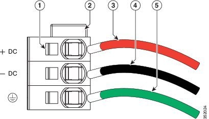
Wiring a 48 V DC Electrical Connector Block
You must connect the ground, negative, and positive DC power cables to a connector block in order to connect the power cables to a 48 V DC power supply.
(注) |
The recommended wire gauge is 8 AWG. The minimum wire gauge is 10 AWG. |
 警告 |
Statement 342—Before Connecting to System Power Supply High leakage currentearth connection essential before connecting to system power supply. |
警告 |
Statement 1024—Ground Conductor This equipment must be grounded. Never defeat the ground conductor or operate the equipment in the absence of a suitably installed ground conductor. Contact the appropriate electrical inspection authority or an electrician if you are uncertain that suitable grounding is available. |
You must turn off the circuit breaker for the DC power cables that you are connecting to prevent electrocution.
| ステップ 1 | Verify that the circuit breaker for the power feed to the replacement power supply is turned off. | ||||||||||||
| ステップ 2 | Remove the DC power connector block from the power supply by doing the following: | ||||||||||||
| ステップ 3 | Strip 0.6 inches (15 mm) of insulation off the DC wires that you are using. | ||||||||||||
| ステップ 4 |
Orient the connector as shown in the following figure with the orange plastic button on top.
|
||||||||||||
| ステップ 5 | Use a small screwdriver to depress the spring-loaded wire retainer lever on the lower spring-cage wire connector. Insert your green (ground) wire into the aperture and then release the lever. | ||||||||||||
| ステップ 6 | Use a small screwdriver to depress the spring-loaded wire retainer lever on the middle spring-cage wire connector. Insert your black (DC negative) wire into the aperture and then release the lever. | ||||||||||||
| ステップ 7 | Use a small screwdriver to depress the spring-loaded wire retainer lever on the upper spring-cage wire connector. Insert your red (DC positive) wire into the aperture and then release the lever. | ||||||||||||
| ステップ 8 | Insert the connector block back into the power supply. Make sure that your red (DC positive) wire aligns with the power supply label, "+ DC". | ||||||||||||
| ステップ 9 | Verify that the other ends of the cables are attached to the DC power source and ground. You are then ready to turn on the DC power source. |
 フィードバック