Cisco Nexus 93120TX NX-OS Mode Switch Hardware Installation Guide
偏向のない言語
この製品のマニュアルセットは、偏向のない言語を使用するように配慮されています。このマニュアルセットでの偏向のない言語とは、年齢、障害、性別、人種的アイデンティティ、民族的アイデンティティ、性的指向、社会経済的地位、およびインターセクショナリティに基づく差別を意味しない言語として定義されています。製品ソフトウェアのユーザーインターフェイスにハードコードされている言語、RFP のドキュメントに基づいて使用されている言語、または参照されているサードパーティ製品で使用されている言語によりドキュメントに例外が存在する場合があります。シスコのインクルーシブランゲージに対する取り組みの詳細は、こちらをご覧ください。
翻訳について
このドキュメントは、米国シスコ発行ドキュメントの参考和訳です。リンク情報につきましては、日本語版掲載時点で、英語版にアップデートがあり、リンク先のページが移動/変更されている場合がありますことをご了承ください。あくまでも参考和訳となりますので、正式な内容については米国サイトのドキュメントを参照ください。
- Updated:
- 2017年6月22日
章のタイトル: Preparing the Site
- Temperature Requirements
- Humidity Requirements
- Altitude Requirements
- Dust and Particulate Requirements
- Minimizing Electromagnetic and Radio Frequency Interference
- Shock and Vibration Requirements
- Grounding Requirements
- Planning for Power Requirements
- Airflow Requirements
- Rack and Cabinet Requirements
- Clearance Requirements
Temperature Requirements
The switch requires an operating temperature of 32 to 104 degrees Fahrenheit (0 to 40 degrees Celsius). If the switch is not operating, the temperature must be between –40 to 158 degrees Fahrenheit (–40 to 70 degrees Celsius).
Humidity Requirements
High humidity can cause moisture to enter the switch. Moisture can cause corrosion of internal components and degradation of properties such as electrical resistance, thermal conductivity, physical strength, and size. The switch is rated to operate at 8- to 80-percent relative humidity, with a humidity gradation of 10 percent per hour. For nonoperating conditions, the switch can withstand from 5- to 95-percent relative humidity.
Buildings in which the climate is controlled by air-conditioning in the warmer months and by heat during the colder months usually maintain an acceptable level of humidity for the switch equipment. However, if the switch is located in an unusually humid location, you should use a dehumidifier to maintain the humidity within an acceptable range.
Altitude Requirements
This switch is rated to operate at altitudes from 0 to 13,123 feet (0 to 4,000 meters). If you operate this switch at a higher altitude (low pressure), the efficiency of forced and convection cooling is reduced and can result in electrical problems that are related to arcing and corona effects. This condition can also cause sealed components with internal pressure, such as electrolytic capacitors, to fail or to perform at a reduced efficiency.
Dust and Particulate Requirements
Exhaust fans cool power supplies and system fans cool switches by drawing in air and exhausting air out through various openings in the chassis. However, fans also ingest dust and other particles, causing contaminant buildup in the switch and increased internal chassis temperature. A clean operating environment can greatly reduce the negative effects of dust and other particles, which act as insulators and interfere with the mechanical components in the switch.
Minimizing Electromagnetic and Radio Frequency Interference
Electromagnetic interference (EMI) and radio frequency interference (RFI) from the switch can adversely affect other devices, such as radio and television (TV) receivers, operating near the switch. Radio frequencies that emanate from the switch can also interfere with cordless and low-power telephones. Conversely, RFI from high-power telephones can cause spurious characters to appear on the switch monitor.
RFI is defined as any EMI with a frequency above 10 kHz. This type of interference can travel from the switch to other devices through the power cable and power source or through the air as transmitted radio waves. The Federal Communications Commission (FCC) publishes specific regulations to limit the amount of EMI and RFI that can be emitted by computing equipment. Each switch meets these FCC regulations.
To reduce the possibility of EMI and RFI, follow these guidelines:
-
Cover all open expansion slots with a blank filler plate.
-
Always use shielded cables with metal connector shells for attaching peripherals to the switch.
When wires are run for any significant distance in an electromagnetic field, interference can occur between the field and the signals on the wires with the following implications:
-
Bad wiring can result in radio interference emanating from the plant wiring.
-
Strong EMI, especially when it is caused by lightning or radio transmitters, can destroy the signal drivers and receivers in the chassis and even create an electrical hazard by conducting power surges through lines into equipment.
 (注) |
To predict and prevent strong EMI, you might need to consult experts in radio frequency interference (RFI). |
The wiring is unlikely to emit radio interference if you use twisted-pair cable with a good distribution of grounding conductors. If you exceed the recommended distances, use a high-quality twisted-pair cable with one ground conductor for each data signal when applicable.
 注意 |
If the wires exceed the recommended distances, or if wires pass between buildings, give special consideration to the effect of a lightning strike in your vicinity. The electromagnetic pulse caused by lightning or other high-energy phenomena can easily couple enough energy into unshielded conductors to destroy electronic switches. You might want to consult experts in electrical surge suppression and shielding if you had similar problems in the past. |
Shock and Vibration Requirements
The switch has been shock- and vibration-tested for operating ranges, handling, and earthquake standards.
Grounding Requirements
The switch is sensitive to variations in voltage supplied by the power sources. Overvoltage, undervoltage, and transients (or spikes) can erase data from the memory or cause components to fail. To protect against these types of problems, ensure that there is an earth-ground connection for the switch. You can connect the grounding pad on the switch either directly to the earth-ground connection or to a fully bonded and grounded rack.
When you properly install the chassis in a grounded rack, the switch is grounded because it has a metal-to-metal connection to the rack. Alternatively, you can ground the chassis by using a customer-supplied grounding cable that meets your local and national installation requirements (we recommend 6-AWG wire for U.S. installations) connected to the chassis with a grounding lug (provided in the switch accessory kit) and to the facility ground.
(注) |
You automatically ground AC power supplies when you connect them to AC power sources. For DC power supplies, you must connect a grounding wire when wiring the power supply to the DC power source. |
Planning for Power Requirements
The switch includes two power supplies (1-to-1 redundancy with current sharing) in one of the following combinations:
(注) |
Both power supplies must be the same type. Do not mix AC, DC, and HVAC/HVDC power supplies in the same chassis. |
(注) |
For n+1 redundancy, you can use one or two power sources for the two power supplies. For n+n redundancy, you must use two power sources with each power supply connected to a separate power source. |
The power supplies are rated to output up to either 1200 W (AC and HVAC/HVDC power supplies) or 930 W (DC power supplies) to the switch, but the switch requires less than those amounts of power from the power supply. To operate the switch you must provision enough power from the power source to cover the requirements of both the switch and a power supply. Typically, this switch and a power supply require about 542 W of power input from the power source, but you must provision as much as 948 W power input from the power source to cover peak demand.
(注) |
Some of the power supply modules have Underwriter Labs (UL) rating capabilities that exceed the switch requirements. When calculating power requirements, use the switch requirements to determine the amount of power required for the power supplies. |
To minimize the possibility of circuit failure, make sure that each power-source circuit used by the switch is dedicated to the switch.
(注) |
For the power cables to use with the power supplies, see Power Cord Specifications. |
Airflow Requirements
The switch is designed to be positioned with its ports in either the front or the rear of the rack depending on your cabling and maintenance requirements. Depending on which side of the switch faces the cold aisle, you must have fan and power supply modules that move the coolant air from the cold aisle to the hot aisle in one of the following ways:
-
Port-side exhaust airflow—Coolant air enters the chassis through the fan and power supply modules in the cold aisle and exhausts through the port end of the chassis in the hot aisle.
-
Port-side intake airflow—Coolant air enters the chassis through the port end in the cold aisle and exhausts through the fan and power supply modules in the hot aisle.
-
Dual-direction airflow—Airflow direction is determined by the airflow direction of the installed fan modules.
You can identify the airflow direction of each fan and power supply module by its coloring as follows:
-
Blue coloring indicates port-side exhaust airflow.
-
Burgundy coloring indicates port-side intake airflow.
-
White coloring on HVAC/HVDC power supplies indicates dual-direction airflow.
-
Gray coloring on DC power supplies indicates port-side exhaust airflow.
-
Green coloring on DC power supplies indicates port-side intake airflow.
(注) |
To prevent the switch from overheating and shutting down, you must position the air intake for the switch in a cold aisle, and all of the fan and power supply modules must have the same direction of airflow (even if their coloring is different). If you mix airflow directions during operations, the switch can over heat and shutdown. If you must change the airflow direction for the switch, you must shutdown the switch before changing the modules. |
Rack and Cabinet Requirements
You can install the following types of racks or cabinets for your switch:
-
Standard perforated cabinets
-
Solid-walled cabinets with a roof fan tray (bottom-to-top cooling)
-
Standard open four-post Telco racks
-
Standard open two-post Telco racks
Work with your cabinet vendors to determine which of their cabinets meet the following requirements or see the Cisco Technical Assistance Center (TAC) for recommendations:
-
Use a standard 19-inch (48.3-cm), four-post Electronic Industries Alliance (EIA) cabinet or rack with mounting rails that conform to English universal hole spacing per section 1 of the ANSI/EIA-310-D-1992 standard.
-
The depth of a four-post rack must be 24 to 32 inches (61.0 to 81.3 cm) between the front and rear mounting rails (for proper mounting of the bottom-support brackets or other mounting hardware).
-
Required clearances between the chassis and the edges of its rack or the interior of its cabinet are as follows:
-
4.5 inches (11.4 cm) between the front of the chassis and the interior of the cabinet (required for cabling).
-
3.0 inches (7.6 cm) between the rear of the chassis and the interior of the cabinet (required for airflow in the cabinet if used).
-
No clearance is required between the chassis and the sides of the rack or cabinet (no side airflow).
-
Additionally, you must have power receptacles located within reach of the power cords used with the switch. For the power cord specifications, see the Power Cord Specifications.
 警告 |
Statement 1048—Rack Stabilization Stability hazard. The rack stabilizing mechanism must be in place, or the rack must be bolted to the floor before you slide the unit out for servicing. Failure to stabilize the rack can cause the rack to tip over. |
Clearance Requirements
You must provide the chassis with adequate clearance between the chassis and any other rack, device, or structure so that you can properly install the chassis, route cables, provide airflow, and maintain the switch. For the clearances required for an installation of this chassis in a four-post rack, see the following figure.
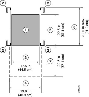
| 1 |
Chassis |
5 |
Depth of the chassis |
| 2 |
Vertical rack-mount posts and rails |
6 |
Maximum extension of the bottom-support rails |
| 3 |
Chassis width |
7 |
Depth of the front clearance area (this equals the depth of the chassis) |
| 4 |
Width of the front clearance area (this equals the width of the chassis with two rack-mount brackets attached to it) |
For the clearances required for a two-post rack installation, see the following figure.
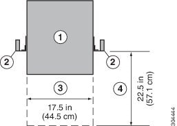
| 1 |
Chassis |
3 |
Chassis width |
| 2 |
Vertical rack-mount posts and rails |
4 |
Service clearance required for replacing the chassis (equals the length of the chassis) |
(注) |
Both the front and rear of the chassis must be open to both aisles for airflow. |
 フィードバック