FCoE の VLAN および仮想インターフェイスの設定

この章は、次の内容で構成されています。

仮想インターフェイスの概要

Cisco Nexus デバイスでは、Fibre Channel over Ethernet(FCoE)がサポートされています。これにより、スイッチとサーバーの間の同じ物理イーサネット接続上でファイバ チャネルおよびイーサネット トラフィックを伝送できます。

FCoE のファイバ チャネル部分は、仮想ファイバ チャネル インターフェイスとして設定されます。論理ファイバ チャネル機能(インターフェイス モードなど)は、仮想ファイバ チャネル インターフェイスで設定できます。

仮想ファイバ チャネル インターフェイスは、いずれかのインターフェイスにバインドしたうえで使用する必要があります。バインド先は、コンバージド ネットワーク アダプタ(CNA)が Cisco Nexus デバイスに直接接続されている場合は物理イーサネット インターフェイス、CNA がレイヤ 2 ブリッジにリモート接続されている場合は MAC アドレス、CNA が 仮想ポートチャネル(vPC)を介してファイバ チャネル フォワーダ(FCF)に接続されている場合は EtherChannel となります。

VE ポート

仮想拡張(VE)ポートは、FCoE ネットワークで拡張ポートとして機能します。VE ポートは、ネットワーク内の複数の FCoE スイッチを接続できます。VE ポートは、物理イーサネット ポートまたはポート チャネルにバインドできます。

Cisco Nexus 9000 シリーズ スイッチでは、VE_Port がバインドされるポート チャネルのメンバ間のトラフィックは、SID、DID、および OXID に基づいてロード バランシングされます。

FCoE トラフィックに対し、すべてのリンクがポート チャネルで使用できるように、 port-channel load-balance ethernet source-dest-port コマンドを入力して、ポート チャネルのロードバランシングを「source-dest-port」に設定します。この設定では、「source-destination-oxid」ロード バランシングが FCoE トラフィックに使用されます。

FCoE VLAN および仮想インターフェイスに関する注意事項および制約事項

FCoE VLAN と仮想ファイバ チャネル(vFC)インターフェイスには、以下の注意事項と制約事項があります。

  • それぞれの vFC インターフェイスは、FCoE 対応イーサネット インターフェイス、EtherChannel インターフェイス、またはリモート接続されたアダプタの MAC アドレスにバインドする必要があります。FCoE は 10 ギガビット、25 ギガビット 40 ギガビット、よび 100 ギガビット イーサネットインターフェイスでサポートされます。

  • 仮想ファイバ チャネル インターフェイスは、いずれかのインターフェイスにバインドしたうえで使用する必要があります。バインド先は、物理イーサネット インターフェイス(コンバージド ネットワーク アダプタ(CNA)が Cisco Nexus デバイスに直接接続されている場合)、MAC アドレス(CNA がレイヤ 2 ブリッジにリモート接続されている場合)、または EtherChannel です。

  • vFC インターフェイスにバインドするイーサネット インターフェイスまたは EtherChannel インターフェイスを設定する際は、次の点に注意してください。

    • イーサネットまたは EthernetChannel インターフェイスは、トランク ポートにする必要があります(switchport mode trunk コマンドを使用します)。

    • vFC の VSAN に対応する FCoE VLAN は、許可 VLAN リストに含まれている必要があります。

    • インターフェイスに MTU 9216 および QoS ポリシーを設定します。デフォルト(サービス ポリシー タイプ qos input default-fcoe-in-policy)またはカスタム QoS ポリシーを使用できます。

    • FCoE VLAN をトランク ポートのネイティブ VLAN として設定しないでください。


      Note


      トランク上のデフォルトの VLAN はネイティブ VLAN です。タグなしフレームはいずれも、ネイティブ VLAN トラフィックとしてトランクを通過します。


    • FCoE には FCoE VLAN だけを使用する必要があります。

    • デフォルト VLAN の VLAN1 を FCoE VLAN として使用しないでください。

    • イーサネット インターフェイスは、PortFast として設定する必要があります(spanning-tree port type edge trunk コマンドを使用します)。


      Note


      スイッチ インターフェイスのトランキングが有効に設定されている場合でも、サーバ インターフェイスにトランキングを設定する必要はありません。サーバから送信される FCoE 以外のトラフィックはすべて、ネイティブ VLAN 上を通過します。


  • vFC インターフェイスは、FCoE Initialization Protocol(FIP)スヌーピング ブリッジに接続された複数のメンバ ポートを持つイーサネット ポートチャネルにバインドできます。

  • 各 vFC インターフェイスは、ただ 1 つの VSAN に対応付けられます。

  • vFC インターフェイスに関連付けられた VSAN は、専用の FCoE 対応 VLAN にマッピングする必要があります。

  • プライベート VLAN では、FCoE はサポートされません。

  • LAN の代替パス用に(同一または別の SAN ファブリックにある)統合アクセス スイッチをイーサネット リンク経由で相互に接続する必要がある場合は、すべての FCoE VLAN をメンバーシップから除外することを、これらのリンクに対して明示的に設定する必要があります。

  • SAN-A および SAN-B ファブリックの FCoE に対してはそれぞれ別々の FCoE VLAN を使用する必要があります。

  • vPC を介した pre-FIP CNA への FCoE 接続はサポートされていません。

  • ポートチャネルにバインド可能な vFCs の最大数は 48 です。

  • ポートチャネルにバインド可能な vFC の最大数は 48(Nexus 6001 の場合は 24)です。


Note


仮想インターフェイスは、管理状態がダウンに設定された状態で作成されます。仮想インターフェイスを動作させるためには、管理状態を明示的に設定する必要があります。


仮想インターフェイスの設定

VSAN から VLAN へのマッピング

SAN 内の VSAN ごとにトラフィックを伝送できるよう、それぞれの統合アクセス スイッチには一意の専用 VLAN を設定する必要があります(VSAN 1 用に VLAN 1002、VSAN 2 用に VLAN 1003 など)。マルチ スパニング ツリーが有効に設定されている場合、FCoE VLAN には別個の MST インスタンスを使用する必要があります。

SUMMARY STEPS

  1. switch# configure terminal
  2. switch(config)# vlan vlan-id
  3. switch(config-vlan)# fcoe [vsan vsan-id]
  4. switch(config-vlan)# exit
  5. (Optional) switch(config)# show vlan fcoe
  6. (Optional) switch(config-if)# copy running-config startup-config

DETAILED STEPS

  Command or Action Purpose

Step 1

switch# configure terminal

グローバル コンフィギュレーション モードを開始します。

Step 2

switch(config)# vlan vlan-id

VLAN コンフィギュレーション モードを開始します。VLAN 番号の有効範囲は 1 ~ 4,096 です。

Step 3

switch(config-vlan)# fcoe [vsan vsan-id]

指定された VLAN で FCoE をイネーブルにします。VSAN 番号を指定しない場合は、対象の VLAN から番号が同じ VSAN へマッピングが作成されます。

対象の VLAN から指定した VSAN へのマッピングを設定します。

Step 4

switch(config-vlan)# exit

VLAN コンフィギュレーション モードを終了します。Cisco Nexus デバイスで設定されたコマンドを実行するには、このモードを終了する必要があります。

Step 5

(Optional) switch(config)# show vlan fcoe

(Optional)

VLAN の FCoE 設定に関する情報を表示します。

Step 6

(Optional) switch(config-if)# copy running-config startup-config

(Optional)

リブートおよびリスタート時に実行コンフィギュレーションをスタートアップ コンフィギュレーションにコピーして、変更を継続的に保存します。

Example

次の例は、VLAN 200 を VSAN 2 にマッピングする方法を示したものです。

switch(config)# vlan 200
switch(config-vlan)# fcoe vsan 2

仮想ファイバ チャネル インターフェイスの作成

仮想ファイバ チャネル インターフェイスを作成できます。仮想ファイバ チャネル インターフェイスは、いずれかの物理インターフェイスにバインドしたうえで使用する必要があります。

SUMMARY STEPS

  1. switch# configure terminal
  2. switch(config)# interface vfc vfc-id
  3. switch(config-if)# bind {interface {ethernet slot/port | port-channel channel-number} | mac-address MAC-address}
  4. (Optional) switch(config-if)# no bind {interface {ethernet slot/port | port-channel channel-number} | mac-address MAC-address}
  5. (Optional) switch(config)# no interface vfc vfc-id

DETAILED STEPS

  Command or Action Purpose

Step 1

switch# configure terminal

グローバル コンフィギュレーション モードを開始します。

Step 2

switch(config)# interface vfc vfc-id

仮想ファイバ チャネル インターフェイスがまだ存在していない場合、それを作成し、インターフェイス コンフィギュレーション モードを開始します。

仮想ファイバ チャネル インターフェイス ID の有効範囲は、1 ~ 8192 です。

Step 3

switch(config-if)# bind {interface {ethernet slot/port | port-channel channel-number} | mac-address MAC-address}

指定されたインターフェイスに仮想ファイバ チャネル インターフェイスをバインドします。

Note


これが 10G ブレイクアウト ポートの場合、slot/port 構文は QSFP-module/port になります。

Step 4

(Optional) switch(config-if)# no bind {interface {ethernet slot/port | port-channel channel-number} | mac-address MAC-address}

(Optional)

指定されたインターフェイスに対する仮想ファイバ チャネル インターフェイスのバインドを解除します。

Note


これが 10G ブレイクアウト ポートの場合、slot/port 構文は QSFP-module/port になります。

Step 5

(Optional) switch(config)# no interface vfc vfc-id

(Optional)

仮想ファイバ チャネル インターフェイスを削除します。

Example

次の例は、イーサネット インターフェイスに仮想ファイバ チャネル インターフェイスをバインドする方法を示したものです。

switch# configure terminal
switch(config)# interface vfc 4
switch(config-if)# bind interface ethernet 1/4

次の例は、Cisco Nexus 2232PP ファブリック エクステンダ(FEX) イーサネット インターフェイスに仮想ファイバ チャネル インターフェイスをバインドする方法を示したものです。

switch# configure terminal
switch(config)# interface vfc 1001
switch(config-if)# bind interface ethernet 100/1/1

次の例は、ポート チャネルに仮想ファイバ チャネル インターフェイスをバインドする方法を示したものです。

switch# configure terminal
switch(config)# interface vfc 3
switch(config-if)# bind interface port-channel 1

次の例は、Nexus デバイス 2232PP FEX 上の仮想ファイバ チャネル インターフェイスをバインドして vPC を作成する方法を示したものです。

switch# configure terminal
switch(config)# interface vfc 1001
switch(config-if)# bind interface ethernet 100/1/1


Note


FCoE をサポートしていない Cisco Nexus FEX にインターフェイスをバインドしようとすると、エラー メッセージが表示されます。


次の例は、MAC アドレスに仮想ファイバ チャネル インターフェイスをバインドする方法を示したものです。

switch# configure terminal
switch(config)# interface vfc 2
switch(config-if)# bind mac-address 00:0a:00:00:00:36

次の例は、Cisco Nexus 2232PP FEX の MAC アドレスに仮想ファイバ チャネル インターフェイスをバインドする方法を示したものです。

switch# configure terminal
switch(config)# interface vfc 1001
switch(config-if)# bind mac-address 00:01:0b:00:00:02

次の例は、仮想ファイバ チャネル インターフェイスを削除する方法を示したものです。

switch# configure terminal
switch(config)# no interface vfc 4

次の例は、イーサネット インターフェイスから仮想ファイバチャネル インターフェイスをバインド解除する方法を示したものです。

switch# configure terminal
switch(config)# int vfc17
switch(config-if)# no bind interface ethernet 1/17
switch(config-if)# exit

vFC インターフェイスの構成

次の手順は、マルチメンバー ポート チャネルのメンバー ポートへの vPC インターフェイスを設定する方法を示しています。

(注)  


4 ポート vPC の設定を解除できるのは、ポート チャネルからメンバー ポートを削除した後だけです。単一のメンバー ポート チャネルでのみ設定を解除できます。


手順の概要

  1. マルチメンバー ポート チャネルを作成します。
  2. 個々のメンバー ポートをマルチメンバー ポート チャネルに追加します。
  3. マルチメンバー ポート チャネルのメンバー ポートに vPC を関連付けます。

手順の詳細


ステップ 1

マルチメンバー ポート チャネルを作成します。

switch(config-vlan)#  interface port-channel 500
switch(config-vlan)# [no]fcoe multi-vfc

ステップ 2

個々のメンバー ポートをマルチメンバー ポート チャネルに追加します。

switch(config-vlan)# interface ethernet 100/1/1
switch(config-vlan)# channel-group 500
switch (config)# interface ethernet 100/1/2
switch(config-if)# channel-group 500

ステップ 3

マルチメンバー ポート チャネルのメンバー ポートに vPC を関連付けます。

switch(config)#  interface vfc 10011
switch(config-vlan)# bind interface ethernet 100/1/1
switch(config-vlan)#  interface vfc 10012
switch (config)#  bind interface ethernet 100/1/2

仮想ファイバ チャネル インターフェイスと VSAN との関連付け

SAN 内の仮想ファブリック(VSAN)ごとにトラフィックを伝送できるよう、それぞれの統合アクセス スイッチには一意の専用 VLAN を設定する必要があります(VSAN 1 用に VLAN 1002、VSAN 2 用に VLAN 1003 など)。MST が有効に設定されている場合、FCoE VLAN には別個の MST インスタンスを使用する必要があります。

手順の概要

  1. switch# configure terminal
  2. switch(config)# vsan database
  3. switch(config-vsan)# vsan vsan-id interface vfc vfc-id
  4. (任意) switch(config-vsan)# no vsan vsan-id interface vfc vfc-id

手順の詳細

  コマンドまたはアクション 目的

ステップ 1

switch# configure terminal

グローバル コンフィギュレーション モードを開始します。

ステップ 2

switch(config)# vsan database

VSAN コンフィギュレーション モードを開始します。

ステップ 3

switch(config-vsan)# vsan vsan-id interface vfc vfc-id

VSAN と仮想ファイバ チャネル インターフェイスの関連付けを設定します。

VSAN 番号は、仮想ファイバ チャネル インターフェイスにバインドされた物理イーサネット インターフェイスの上の VLAN にマッピングする必要があります。

ステップ 4

(任意) switch(config-vsan)# no vsan vsan-id interface vfc vfc-id

(任意)

VSAN と仮想ファイバ チャネル インターフェイスの関連付けを解除します。

次の例は、仮想ファイバ チャネル インターフェイスを VSAN に関連付ける方法を示したものです。

switch# configure terminal
switch(config)# vsan database
switch(config-vsan)# vsan 2 interface vfc 4

暗黙的仮想ファイバ チャネル ポート チャネル インターフェイスの作成

仮想ファイバー チャネル(vFC)を構築し、1 つのコマンドを使用してそれをイーサネット インターフェイスまたはポート チャネルに暗黙的にバインドすることができます。このためには、vFC 識別子がイーサネット インターフェイスまたはポート チャネル識別子とマッチする必要があります。イーサネット インターフェイスは、モジュール(スロットまたはポート)インターフェイス(スロット/QSFP-モジュール/ポート)にすることができます。

Note


ブレイクアウト ポートに暗黙的な vFC を構築することはできません。


仮想ファイバ チャネル インターフェイスの設定

Before you begin

  • FCoE の正しいライセンスがインストールされていることを確認します。

  • FCoE がイネーブルになっていることを確認します。

Procedure


Step 1

グローバル コンフィギュレーション モードを開始します。

switch# configure terminal

Step 2

vFC を構築します(まだ存在しない場合)。

さらに、vfc slot/port は、vFC をイーサネット スロット/ポート インターフェイスにバインドします。vFC スロット/QSFP モジュール/ポートは、vFC をブレークアウト インターフェイスにバインドします。

switch(config) # interface vfc {id | slot/port | slot/QSFP-module/port }

Step 3

vFC インターフェイスを起動します。

switch(config-if) # no shutdown

Step 4

インターフェイス コンフィギュレーション モードを終了します。

switch(config-if) # exit


仮想ファイバ チャネル インターフェイスの設定

次の例は、イーサネット インターフェイスに仮想ファイバ チャネル インターフェイスを暗黙的にバインドする方法を示したものです。

switch# configure terminal
switch(config)# interface eth1/11
switch(config-if)# switchport mode trunk
switch(config-if)# mtu 9216
switch(config-if)# service-policy type qos input default-fcoe-in-policy
switch(config-if)# no shutdown

switch(config)# interface vfc1/11
switch(config-if)# no shutdown
switch(config-if)# exit
switch(config)#

switch(config)# vsan database
switch(config-vsan-db)# vsan 10
switch(config-vsan-db)# exit
switch(config)#

switch(config)# vlan 10
switch(config-vlan)# fcoe vsan 10
switch(config-vlan)# exit
switch(config)#

switch(config)# vsan database
switch(config-vsan-db)# vsan 10 interface vfc1/11
switch(config-vsan-db)# exit
switch(config)#
switch(config)# show interface vfc1/11
vfc1/11 is trunking (Not all VSANs UP on the trunk)
Bound interface is Ethernet1/11
Hardware is Ethernet
Port WWN is 20:0b:00:de:fb:9d:0e:a0
Admin port mode is F, trunk mode is on
snmp link state traps are enabled
Port mode is TF
Port vsan is 10
Operating Speed is 10 Gbps
Admin Speed is auto
Trunk vsans (admin allowed and active) (1,10)
Trunk vsans (up) (10)
Trunk vsans (isolated) ()
Trunk vsans (initializing) (1)
11 fcoe in packets
1692 fcoe in octets
0 fcoe out packets
0 fcoe out octets
Interface last changed at Mon Dec 16 09:03:33 2019

switch(config)#

仮想ファイバ チャネル の設定:ポート チャネル インターフェイス

Procedure


Step 1

グローバル コンフィギュレーション モードを開始します。

switch# configure terminal

Step 2

番号に基づいてイーサネット ポート チャネルに暗黙的にバインドする vFC を構築します。

ポート番号の範囲は 1 ~ 4096 です。

switch(config) # interface vfc-port-channel port number

Step 3

vFC ポートを起動します。

switch(config-if) # no shutdown

Step 4

現在のインターフェイス コンフィギュレーション モードを終了します。

switch(config-if) # exit


仮想ファイバ チャネル の設定:ポート チャネル インターフェイス

この例は、イーサネット ポート チャネルに暗黙的にバインドする vFC ポート チャネルを構築する方法を示しています。

switch# configure terminal
switch(config)# interface port-channel 10
switch(config-if)# switchport
switch(config-if)# switchport mode trunk
switch(config-if)# mtu 9216
switch(config-if)# service-policy type qos input default-fcoe-in-policy
switch(config-if)# no shutdown
switch(config-if)# exit

switch(config)# interface eth1/49
switch(config-if)# channel-group 10 force
switch(config-if)# no shutdown
switch(config-if)# exit

switch# configure terminal
switch(config)# interface vfc-port-channel 10
switch(config-if)# no shutdown
switch(config-if)# exit

switch(config)# vlan 10
switch(config-vlan)# fcoe vsan 10
switch(config-vlan)# exit
switch(config)#

switch(config)# vsan database
switch(config-vsan-db)# vsan 10 interface vfc-port-channel 10
switch(config-vsan-db)# exit

switch(config)# show interface vfc-port-channel 10
vfc-po10 is trunking (Not all VSANs UP on the trunk)
Bound interface is port-channel10
Hardware is Ethernet
Port WWN is 25:1b:00:de:fb:9d:0e:a0
Admin port mode is F, trunk mode is on
snmp link state traps are enabled
Port mode is TF
Port vsan is 10
Operating Speed is 40 Gbps
Admin Speed is auto
Trunk vsans (admin allowed and active) (1,10)
Trunk vsans (up) (10)
Trunk vsans (isolated) ()
Trunk vsans (initializing) (1)
11 fcoe in packets
1236 fcoe in octets
0 fcoe out packets
0 fcoe out octets
Interface last changed at Mon Dec 16 08:56:13 2019


仮想インターフェイスの確認

仮想インターフェイスに関する設定情報を表示するには、次の作業のいずれかを行います。

コマンド

目的

switch# show interface vfc vfc-id

指定されたファイバ チャネル インターフェイスの詳細な設定を表示します。

switch# show interface brief

すべてのインターフェイスのステータスが表示されます。

switch# show vlan fcoe

FCoE VLAN から VSAN へのマッピングを表示します。

次の例は、イーサネット インターフェイスにバインドされた仮想ファイバ チャネル インターフェイスを表示する方法を示したものです。

switch# show interface vfc 11
vfc11 is trunking (Not all VSANs UP on the trunk)

Bound interface is Ethernet1/11
Hardware is Ethernet
Port WWN is 20:0a:00:de:fb:9d:0e:df
Admin port mode is F, trunk mode is on
snmp link state traps are enabled
Port mode is TF
Port vsan is 10
Operating Speed is 10 Gbps
Admin Speed is auto
Trunk vsans (admin allowed and active) (1,10)
Trunk vsans (up) (10)
Trunk vsans (isolated) ()
Trunk vsans (initializing) (1)
2 fcoe in packets
152 fcoe in octets
0 fcoe out packets
0 fcoe out octets
Interface last changed at Wed Dec 18 10:36:58 2019

次の例は、MAC アドレスにバインドされた仮想ファイバ チャネル インターフェイスを表示する方法を示したものです。

switch# show interface vfc 11

vfc11 is trunking (Not all VSANs UP on the trunk)
Bound MAC is 0090.faf8.7513
Hardware is Ethernet
Port WWN is 20:0a:00:de:fb:9d:0e:df
Admin port mode is F, trunk mode is on
snmp link state traps are enabled
Port mode is TF
Port vsan is 10
Operating Speed is 10 Gbps
Admin Speed is auto
Trunk vsans (admin allowed and active) (1,10)
Trunk vsans (up) (10)
Trunk vsans (isolated) ()
Trunk vsans (initializing) (1)
3 fcoe in packets
228 fcoe in octets
0 fcoe out packets
0 fcoe out octets
Interface last changed at Mon Dec 16 09:09:02 2019

次の例は、スイッチ上のすべてのインターフェイスのステータスを表示する方法を示したものです(簡略化のため、出力の一部は省略)。

switch# show interface brief

--------------------------------------------------------------------------------
Port VRF Status IP Address Speed MTU
--------------------------------------------------------------------------------
mgmt0 -- up 9.9.9.9 1000 1500
--------------------------------------------------------------------------------
Ethernet VLAN Type Mode Status Reason Speed Port
Interface Ch #
--------------------------------------------------------------------------------
Eth1/1 1 eth trunk up none 100G(D) 1
Eth1/2 1 eth trunk up none 100G(D) 1
Eth1/3 -- eth routed down Administratively down auto(D) --
Eth1/4 -- eth routed down XCVR not inserted auto(D) --
Eth1/5 -- eth routed down Administratively down auto(D) --
Eth1/6 -- eth routed down Administratively down auto(D) --
Eth1/7 1 eth trunk up none 40G(D) 601
Eth1/8 -- eth routed down XCVR not inserted auto(D) --
Eth1/14 -- eth routed down XCVR not inserted auto(D) --
Eth1/16 -- eth routed down XCVR not inserted auto(D) --
Eth1/17 -- eth routed down XCVR not inserted auto(D) --
Eth1/18/1 1 eth trunk up none 10G(D) 181
Eth1/18/2 1 eth trunk up none 10G(D) 560
Eth1/18/3 1 eth trunk up none 10G(D) 560
Eth1/18/4 1 eth trunk up none 10G(D) 560
Eth1/19 -- eth routed down Administratively down auto(D) --
Eth1/20 -- eth routed down Administratively down auto(D) --
Eth1/21 -- eth routed down XCVR not inserted auto(D) --
Eth1/22 -- eth routed down XCVR not inserted auto(D) --
Eth1/23 -- eth routed down XCVR not inserted auto(D) --
Eth1/24 -- eth routed down XCVR not inserted auto(D) --
Eth1/25 1 eth trunk up none 100G(D) 2500
Eth1/26 1 eth trunk up none 40G(D) 26
Eth1/27 -- eth routed down XCVR not inserted auto(D) --
Eth1/28 -- eth routed down XCVR not inserted auto(D) --
Eth1/29 -- eth routed down XCVR not inserted auto(D) --
Eth1/31 1 eth trunk up none 40G(D) 559
Eth1/32 -- eth routed down XCVR not inserted auto(D) --
Eth1/33 -- eth routed down XCVR not inserted auto(D) --
Eth1/34 -- eth routed down XCVR not inserted auto(D) --
Eth1/35 -- eth routed down Administratively down auto(D) --
Eth1/36/1 -- eth routed down Administratively down auto(D) --
Eth1/36/2 -- eth routed down Administratively down auto(D) --
Eth1/36/3 -- eth routed down Administratively down auto(D) --
Eth1/36/4 -- eth routed down Administratively down auto(D) --

------------------------------------------------------------------------------------------
Port-channel VLAN Type Mode Status Reason Speed Protocol
Interface
------------------------------------------------------------------------------------------
Po1 1 eth trunk up none a-100G(D) lacp
Po26 1 eth trunk up none a-40G(D) none
Po181 1 eth trunk up none a-10G(D) none
Po559 1 eth trunk up none a-40G(D) none
Po560 1 eth trunk up none a-10G(D) none
Po601 1 eth trunk up none a-40G(D) none
Po2500 1 eth trunk up none a-100G(D) none

-------------------------------------------------------------------------------
Interface Vsan Admin Admin Status SFP Oper Oper Port
Mode Trunk Mode Speed Channel
Mode (Gbps)
-------------------------------------------------------------------------------
fc1/9/1 1 E on trunking swl TE 8 224
fc1/9/2 1 E on trunking swl TE 8 224
fc1/9/3 1 E on trunking swl TE 8 224
fc1/9/4 1 E on trunking swl TE 8 224
fc1/10/1 1 E on trunking swl TE 8 224
fc1/10/2 1 E on trunking swl TE 8 224
fc1/10/3 1 E on trunking swl TE 8 224
fc1/10/4 1 E on trunking swl TE 8 224
fc1/11/1 1 E on trunking swl TE 8 224
fc1/11/2 1 E on trunking swl TE 8 224
fc1/11/3 1 E on trunking swl TE 8 224
fc1/11/4 1 E on trunking swl TE 8 224
fc1/12/1 1 auto on down swl -- -- --
fc1/12/2 1 auto on down swl -- -- --
fc1/12/3 1 auto on down swl -- -- --
fc1/12/4 1 auto on down swl -- -- --
fc1/13/1 1 E on trunking swl TE 8 225
fc1/13/2 1 E on trunking swl TE 8 225
fc1/13/3 1 E on trunking swl TE 8 225
fc1/13/4 1 E on trunking swl TE 8 225
fc1/15/1 501 auto off up swl F 32 --
fc1/15/2 501 F on trunking swl TF 32 114
fc1/15/3 501 F off up swl F 32 --
fc1/15/4 1 F on trunking swl TF 32 118
fc1/30/1 1 E off notConnected swl -- -- --
fc1/30/2 1 E off notConnected swl -- -- --
fc1/30/3 1 E on trunking swl TE 32 --
fc1/30/4 1 E on notConnected swl -- -- --

-------------------------------------------------------------------------------
Interface Vsan Admin Status Oper Oper IP
Trunk Mode Speed Address
Mode (Gbps)
-------------------------------------------------------------------------------
san-port-channel114 501 on trunking TF 32 --
san-port-channel118 1 on trunking TF 32 --
san-port-channel224 1 on trunking TE 88 --
san-port-channel225 1 on trunking TE 32 --

-------------------------------------------------------------------------------
Interface Vsan Admin Admin Status Bind Oper Oper
Mode Trunk Info Mode Speed
Mode (Gbps)
-------------------------------------------------------------------------------
vfc1 501 F on trunking Ethernet1/26 TF 40
vfc2 501 F on trunking e02f.6d08.cda9 TF auto
vfc560 1 F on trunking port-channel560 TF 30
vfc1/25 501 F on trunking Ethernet1/25 TF 100

-------------------------------------------------------------------------------
Interface Vsan Admin Admin Status Bind Oper Oper
Mode Trunk Info Mode Speed
Mode (Gbps)
-------------------------------------------------------------------------------
vfc-po559 1 F on trunking port-channel559 TF 40
vfc-po601 501 F on trunking port-channel601 TF 40

次の例は、スイッチにおける VLAN と VSAN とのマッピングを表示する方法を示したものです。

switch# show vlan fcoe
VLAN      VSAN      Status
--------  --------  --------
15        15        Operational
20        20        Operational
25        25        Operational
30        30        Non-operational

VSAN から VLAN へのマッピングの設定例

次に示すのは、FCoE VLAN および仮想ファイバ チャネル インターフェイスの設定例です。

手順の概要

  1. 関連する VLAN を有効にし、その VLAN を VSAN へマッピングします。
  2. 物理イーサネット インターフェイス上で VLAN を設定します。
  3. 仮想ファイバ チャネル インターフェイスを作成し、それを物理イーサネット インターフェイスにバインドします。
  4. 仮想ファイバ チャネル インターフェイスを VSAN に関連付けます。
  5. (任意)VSAN のメンバーシップ情報を表示します。
  6. (任意)仮想ファイバ チャネル インターフェイスに関するインターフェイス情報を表示します。

手順の詳細


ステップ 1

関連する VLAN を有効にし、その VLAN を VSAN へマッピングします。

switch(config)# vlan 200
switch(config-vlan)# fcoe vsan 2
switch(config-vlan)# exit
 

ステップ 2

物理イーサネット インターフェイス上で VLAN を設定します。

switch(config)# interface eth1/11
switch(config)# spanning-tree port type edge trunk
switch(config-if)# switchport mode trunk
switch(config-if)# switchport trunk allowed vlan 1,200
switch(config-if)# mtu 9216
switch(config-if)# service-policy type qos input default-fcoe-in-policy
switch(config-if)# exit

ステップ 3

仮想ファイバ チャネル インターフェイスを作成し、それを物理イーサネット インターフェイスにバインドします。

switch(config)# interface vfc 11
switch(config-if)# bind interface ethernet 1/4
switch(config-if)# no shutdown
switch(config-if)# exit

(注)  


デフォルトでは、仮想ファイバ チャネル インターフェイスはすべて VSAN 1 上に存在します。VLAN から VSAN へのマッピングを VSAN 1 以外の VSAN に対して行う場合は、ステップ 4 へ進みます。

ステップ 4

仮想ファイバ チャネル インターフェイスを VSAN に関連付けます。

switch(config)# vsan database
switch(config-vsan-db)# vsan 2
switch(config-vsan-db)# vsan 2 interface vfc 11
switch(config-vsan)# exit

ステップ 5

(任意)VSAN のメンバーシップ情報を表示します。

switch# show vsan 2 membership
vsan 2 interfaces
           vfc 11

ステップ 6

(任意)仮想ファイバ チャネル インターフェイスに関するインターフェイス情報を表示します。

switch# show interface vfc 11

vfc11 is trunking (Not all VSANs UP on the trunk)
Bound interface is Ethernet1/11
Hardware is Ethernet
Port WWN is 20:0a:00:de:fb:9d:0e:df
Admin port mode is F, trunk mode is on
snmp link state traps are enabled
Port mode is TF
Port vsan is 2
Operating Speed is 10 Gbps
Admin Speed is auto
Trunk vsans (admin allowed and active) (1-2,10)
Trunk vsans (up) (2)
Trunk vsans (isolated) ()
Trunk vsans (initializing) (1,10)
2 fcoe in packets
152 fcoe in octets
0 fcoe out packets
0 fcoe out octets
Interface last changed at Mon Dec 16 09:22:25 2019


FCoE over Enhanced vPC

イーサネット トラフィックは、Enhanced vPC トポロジでは FEX とスイッチ ペア間でデュアル ホーム接続されますが、FCoE トラフィックは、SAN 分離を維持するためにシングル ホーム接続される必要があります。したがって、Enhanced vPC が FCoE をサポートする一方で、SAN 分離と高 FCoE 帯域幅が必要な場合は、シングル ホーム接続の FEX トポロジの方が望ましいこともあります。

シングル ホーム接続のトポロジに対する、Enhanced vPC のデメリットを考慮してください。

  • 一般的な SAN ネットワークには、SAN A と SAN B という 2 つのファブリックがあり、その間のトラフィックは分離されています。Enhanced vPC トポロジでは、各スイッチは FEX によってペア化されており(シングル ホーム)、1 つの FEX からの FCoE トラフィックが 1 つのスイッチにしか送信されないようになっています。一方、イーサネット トラフィックは、各 FEX と両方のスイッチ間でデュアル ホーム接続されます。FEX からの FCoE トラフィックは 1 つのスイッチにしか送受信されず、イーサネット トラフィックは両方に送受信されるため、FEX アップリンクのトラフィック負荷は均等化されません。

  • 8 つのアップリンク ポートを持つ FEX では、イーサネット トラフィックは 8 ポートをすべて使用しますが、シングル ホーム接続の FCoE トラフィックは、このトポロジでは 4 つのポートしか使用しないよう制限されているため、FCoE で使用可能な最大帯域幅も制限されます。さらに、共有リンクのデフォルトの QoS テンプレートは、FCoE トラフィックに対してリンク帯域幅の半分しか割り当てず、残りの半分はイーサネット トラフィックに割り当てられるという制限もあります。

  • FEX を使用する Enhanced vPC トポロジでは、ホスト vPC は 2 ポートに制限されており、FEX あたり 1 ポートずつ使用します。

次の図は、それぞれ異なる Cisco Nexus デバイスに関連付けられた、2 つの Cisco Nexus 2000 FEX を使用するシステムの FCoE トラフィック フローを示します。

図 1. FCoE over Enhanced vPC


FCoE over Enhanced vPC の設定

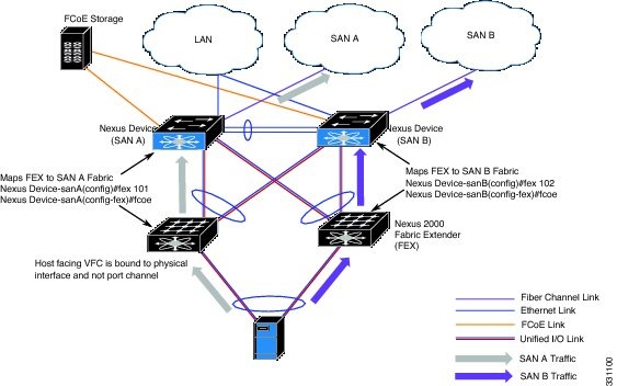
SAN 分離を維持するため、FCoE トラフィックはシングル ホーム接続される必要があります。まず、FEX を 1 つのスイッチと関連付けます。FEX とスイッチが関連付けられると、仮想ファイバ チャネル(vFC)インターフェイスを作成し、ポートにバインドします。

最初のピアで FEX とスイッチをペアリングすると、SAN トラフィックを分離できるよう別のポート番号を使用して 2 番目のピアでも同じ設定を繰り返します。設定が異なっても、整合性エラーが発生することはありません。これは、Enhanced vPC 設定の FCoE の部分は、vPC 整合性チェックの対象となっていないためです。

始める前に

FCoE over Enhanced vPCの制限事項を確認してください。

手順の概要

  1. switch# configure terminal
  2. switch(config) # fex fex-chassis_ID
  3. switch(config-fex) # fcoe
  4. switch(config-fex) # interface vfc vfc-id
  5. switch(config-if) # bind interface ethernet [fex-chassis-ID/]slot/port
  6. switch(config-if) # no shutdown
  7. (任意) switch(config-if) # end
  8. (任意) switch(config)# copy running-config startup-config

手順の詳細

  コマンドまたはアクション 目的

ステップ 1

switch# configure terminal

グローバル コンフィギュレーション モードを開始します。

ステップ 2

switch(config) # fex fex-chassis_ID

指定された FEX のコンフィギュレーション モードを開始します。

fex-chassis_ID の範囲は 100 ~ 199 です。

ステップ 3

switch(config-fex) # fcoe

このスイッチにのみ FCoE トラフィックを送信するよう、FEX を設定します。

ステップ 4

switch(config-fex) # interface vfc vfc-id

仮想ファイバ チャネル インタフェースのコンフィギュレーション モードを開始します。インターフェイスが存在しない場合は、このコマンドにより、インターフェイスが作成されます。

vfc-id の範囲は、1 ~ 8192 です。

ステップ 5

switch(config-if) # bind interface ethernet [fex-chassis-ID/]slot/port

vFC インターフェイスを指定された物理イーサネット インターフェイスにバインドします。

fex-chassis_ID の範囲は 100 ~ 199 です。slot は 1 にする必要があります。FCoE では、port の範囲は 1 ~ 32 です。

(注)  


これが 10G ブレイクアウト ポートの場合、slot/port 構文は QSFP-module/port になります。

ステップ 6

switch(config-if) # no shutdown

インターフェイスを、デフォルトの操作状態に戻します。

ステップ 7

(任意) switch(config-if) # end

(任意)

特権 EXEC モードに戻ります。

ステップ 8

(任意) switch(config)# copy running-config startup-config

(任意)

リブートおよびリスタート時に実行コンフィギュレーションをスタートアップ コンフィギュレーションにコピーして、変更を継続的に保存します。

この例では、各 FEX を FCoE トラフィックのスイッチにペアリングする方法を示します。

nexus5000-sanA# configure terminal
nexus5000-sanA(config) # fex 101
nexus5000-sanA(config-fex) # fcoe
nexus5000-sanA(config-fex) # interface vfc 1
nexus5000-sanA(config-if) # bind interface ethernet 101/1/1
nexus5000-sanA(config-if) # no shutdown
nexus5000-sanA(config-if) # end
nexus5000-sanA# copy running-config startup-config
nexus5000-sanA#

nexus5000-sanB# configure terminal
nexus5000-sanB(config) # fex 102
nexus5000-sanB(config-fex) # fcoe
nexus5000-sanB(config-fex) # interface vfc 1
nexus5000-sanB(config-if) # bind interface ethernet 102/1/1
nexus5000-sanB(config-if) # no shutdown
nexus5000-sanB(config-if) # end
nexus5000-sanB# copy running-config startup-config
nexus5000-sanB#

nexus5500-sanA# configure terminal
nexus5500-sanA(config) # fex 101
nexus5500-sanA(config-fex) # fcoe
nexus5500-sanA(config-fex) # interface vfc 1
nexus5500-sanA(config-if) # bind interface ethernet 101/1/1
nexus5500-sanA(config-if) # no shutdown
nexus5500-sanA(config-if) # end
nexus5500-sanA# copy running-config startup-config
nexus5500-sanA#

nexus5500-sanB# configure terminal
nexus5500-sanB(config) # fex 102
nexus5500-sanB(config-fex) # fcoe
nexus5500-sanB(config-fex) # interface vfc 1
nexus5500-sanB(config-if) # bind interface ethernet 102/1/1
nexus5500-sanB(config-if) # no shutdown
nexus5500-sanB(config-if) # end
nexus5500-sanB# copy running-config startup-config
nexus5500-sanB#

nexus6000-sanA# configure terminal
nexus6000-sanA(config) # fex 101
nexus6000-sanA(config-fex) # fcoe
nexus6000-sanA(config-fex) # interface vfc 1
nexus6000-sanA(config-if) # bind interface ethernet 101/1/1
nexus6000-sanA(config-if) # no shutdown
nexus6000-sanA(config-if) # end
nexus6000-sanA# copy running-config startup-config
nexus6000-sanA#

nexus6000-sanB# configure terminal
nexus6000-sanB(config) # fex 102
nexus6000-sanB(config-fex) # fcoe
nexus6000-sanB(config-fex) # interface vfc 1
nexus6000-sanB(config-if) # bind interface ethernet 102/1/1
nexus6000-sanB(config-if) # no shutdown
nexus6000-sanB(config-if) # end
nexus6000-sanB# copy running-config startup-config
nexus6000-sanB#

vPC による SAN ブート

1 つの VFC インターフェイスが vPC メンバーにバインドされている場合、Cisco Nexus シリーズ スイッチは SAN ブートを使用できます。複数のインターフェイスを複数のメンバにバインドすることはできません。

  • vPC に割り当てられたポートを含む FEX が Nexus スイッチに関連付けられていること。

  • vPC メンバには、1 つの VFC インターフェイスしかバインドされていないこと。複数のインターフェイスを複数のメンバにバインドすることはできません。


(注)  


以前のすべての設定、および対応トポロジとの下位互換性を確保するには、Enhanced vPC を使用しないストレート-スルー FEX トポロジで FEX を設定する必要があります。


vPC による SAN ブートの設定例

この例では、仮想ファイバ チャネル インターフェイス 1 はファブリック A の物理イーサネット インターフェイス 101/1/1 、およびファブリック B のインターフェイス 102/1/1 にバインドされています。インターフェイスはまた、両方のファブリックの仮想ポート チャネル 1 にも関連付けられています。

nexus5000-sanA(config) # interface vfc 1
nexus5000-sanA(config-if) # bind interface eth 101/1/1
nexus5000-sanA(config) # interface eth 101/1/1
nexus5000-sanA(config-if) # channel-group 1 mode active
nexus5000-sanA(config-if) # interface port-channel 1
nexus5000-sanA(config-if) # vpc 1
nexus5000-sanA(config-if) #

nexus5000-sanB(config) # interface vfc 1
nexus5000-sanB(config-if) # bind interface eth 102/1/1
nexus5000-sanB(config) # interface eth 102/1/1
nexus5000-sanB(config-if) # channel-group 1 mode active
nexus5000-sanB(config-if) # interface port-channel 1
nexus5000-sanB(config-if) # vpc 1
nexus5000-sanB(config-if) #
nexus5500-sanA(config) # interface vfc 1
nexus5500-sanA(config-if) # bind interface eth 101/1/1
nexus5500-sanA(config) # interface eth 101/1/1
nexus5500-sanA(config-if) # channel-group 1 mode active
nexus5500-sanA(config-if) # interface port-channel 1
nexus5500-sanA(config-if) # vpc 1
nexus5500-sanA(config-if) #

nexus5500-sanB(config) # interface vfc 1
nexus5500-sanB(config-if) # bind interface eth 102/1/1
nexus5500-sanB(config) # interface eth 102/1/1
nexus5500-sanB(config-if) # channel-group 1 mode active
nexus5500-sanB(config-if) # interface port-channel 1
nexus5500-sanB(config-if) # vpc 1
nexus5500-sanB(config-if) #
nexus5600-sanA(config) # interface vfc 1
nexus5600-sanA(config-if) # bind interface eth 101/1/1
nexus5600-sanA(config) # interface eth 101/1/1
nexus5600-sanA(config-if) # channel-group 1 mode active
nexus5600-sanA(config-if) # interface port-channel 1
nexus5600-sanA(config-if) # vpc 1
nexus5600-sanA(config-if) #

nexus5600-sanB(config) # interface vfc 1
nexus5600-sanB(config-if) # bind interface eth 102/1/1
nexus5600-sanB(config) # interface eth 102/1/1
nexus5600-sanB(config-if) # channel-group 1 mode active
nexus5600-sanB(config-if) # interface port-channel 1
nexus5600-sanB(config-if) # vpc 1
nexus5600-sanB(config-if) #
nexus6000-sanA(config) # interface vfc 1
nexus6000-sanA(config-if) # bind interface eth 101/1/1
nexus6000-sanA(config) # interface eth 101/1/1
nexus6000-sanA(config-if) # channel-group 1 mode active
nexus6000-sanA(config-if) # interface port-channel 1
nexus6000-sanA(config-if) # vpc 1
nexus6000-sanA(config-if) #

nexus6000-sanB(config) # interface vfc 1
nexus6000-sanB(config-if) # bind interface eth 102/1/1
nexus6000-sanB(config) # interface eth 102/1/1
nexus6000-sanB(config-if) # channel-group 1 mode active
nexus6000-sanB(config-if) # interface port-channel 1
nexus6000-sanB(config-if) # vpc 1
nexus6000-sanB(config-if) #