IP アドレッシング:ポイントツーポイント(P2P)または IP アンナンバード リンク。リーフ スイッチ ノードとスパイン スイッチ ノード間の例として、ポイントツーポイントリンクごとに、通常 /30 IP マスクを割り当てる必要があります。オプションで、/31
マスクまたは IP アンナンバード リンクを割り当てることができます。IP アンナンバード アプローチは、アドレッシングの観点から見ると、より少ない IP アドレスを使用します。OSPF または IS-IS プロトコル アンダーレイの IP アンナンバード
オプションは、IP アドレスの使用を最小限に抑えます。
interface Ethernet 1/41
   description Link to Spine S1
   no switchport
   ip address 198.51.100.1/31
   mtu 9192
   ip router ospf UNDERLAY area 0.0.0.0
   ip ospf network point-to-point
ip ospf network point-to-point コマンドは、OSPF ネットワークをポイントツーポイント ネットワークとして設定します。
OSPF インスタンスは、リコールを改善するために UNDERLAY としてタグ付けされています。
OSPF ループバック インターフェイス コンフィギュレーション(リーフ スイッチ V1)
リーフ スイッチ V1 の OSPF ルータ ID として使用できるように、ループバック インターフェイスを設定します。
(config) #
interface loopback 0
   ip address 10.1.1.54/32
   ip router ospf UNDERLAY area 0.0.0.0
interface Ethernet 1/41
   description Link to VTEP V1
   ip address 198.51.100.2/31
   mtu 9192
   ip router ospf UNDERLAY area 0.0.0.0
   ip ospf network point-to-point
   no shutdown
Cisco Nexus 5600 シリーズ スイッチには 9192 の MTU を使用します。
(注)
リンクの両端の MTU サイズは同じに設定する必要があります。
OSPF ループバック インターフェイスの設定(スパイン スイッチ S1)
スパイン スイッチ S1 の OSPF ルータ ID として使用できるように、ループバック インターフェイスを設定します。
(config) #
interface loopback 0
   ip address 10.1.1.53/32
   ip router ospf UNDERLAY area 0.0.0.0
interface Ethernet1/41
  description Link to Spine S1
  mtu 9192
  ip ospf network point-to-point
  ip unnumbered loopback0
  ip router ospf UNDERLAY area 0.0.0.0
Cisco Nexus 5600 シリーズ スイッチには 9192 の MTU を使用します。
ip ospf network point-to-point コマンドは、OSPF ネットワークをポイントツーポイント ネットワークとして設定します。
OSPF ループバック インターフェイスの設定
リーフ スイッチ V1 の OSPF ルータ ID として使用できるように、ループバック インターフェイスを設定します。
(config) #
interface loopback0
  ip address 10.1.1.54/32
  ip router ospf UNDERLAY area 0.0.0.0
interface Ethernet1/41
  description Link to VTEP V1
  mtu 9192
  ip ospf network point-to-point
  ip unnumbered loopback0
  ip router ospf UNDERLAY area 0.0.0.0
Cisco Nexus 5600 シリーズ スイッチには 9192 の MTU を使用します。
OSPF ループバック インターフェイス設定(スパイン スイッチ S1)
スパイン スイッチ S1 の OSPF ルータ ID として使用できるように、ループバック インターフェイスを設定します。
(config) #
interface loopback0
  ip address 10.1.1.53/32
  ip router ospf UNDERLAY area 0.0.0.0
VTEP V2、V3、および V4 とスパイン スイッチ間の IP アンナンバード リンクを接続する手順を繰り返します。
OSPF 検証
OSP F設定を確認するには、次のコマンドを使用します。
Leaf-Switch-V1# show ip ospf

 Routing Process UNDERLAY with ID 10.1.1.54 VRF default
 Routing Process Instance Number 1
 Stateful High Availability enabled
 Graceful-restart is configured
   Grace period: 60 state: Inactive
   Last graceful restart exit status: None
 Supports only single TOS(TOS0) routes
 Supports opaque LSA
 Administrative distance 110
 Reference Bandwidth is 40000 Mbps
 SPF throttling delay time of 200.000 msecs,
   SPF throttling hold time of 1000.000 msecs,
   SPF throttling maximum wait time of 5000.000 msecs
 LSA throttling start time of 0.000 msecs,
   LSA throttling hold interval of 5000.000 msecs,
   LSA throttling maximum wait time of 5000.000 msecs
 Minimum LSA arrival 1000.000 msec
 LSA group pacing timer 10 secs
 Maximum paths to destination 8
 Number of external LSAs 0, checksum sum 0
 Number of opaque AS LSAs 0, checksum sum 0
 Number of areas is 1, 1 normal, 0 stub, 0 nssa
 Number of active areas is 1, 1 normal, 0 stub, 0 nssa
 Install discard route for summarized external routes.
 Install discard route for summarized internal routes.
   Area BACKBONE(0.0.0.0)
        Area has existed for 03:12:54
        Interfaces in this area: 2 Active interfaces: 2
        Passive interfaces: 0  Loopback interfaces: 1
        No authentication available
        SPF calculation has run 5 times
         Last SPF ran for 0.000195s
        Area ranges are
        Number of LSAs: 3, checksum sum 0x196c2
Leaf-Switch-V1# show ip ospf interface

loopback0 is up, line protocol is up
    IP address 10.1.1.54/32
    Process ID UNDERLAY VRF default, area 0.0.0.0
    Enabled by interface configuration
    State LOOPBACK, Network type LOOPBACK, cost 1
    Index 1
 Ethernet1/41 is up, line protocol is up
    Unnumbered interface using IP address of loopback0 (10.1.1.54)
    Process ID UNDERLAY VRF default, area 0.0.0.0
    Enabled by interface configuration
    State P2P, Network type P2P, cost 4
    Index 2, Transmit delay 1 sec
    1 Neighbors, flooding to 1, adjacent with 1
    Timer intervals: Hello 10, Dead 40, Wait 40, Retransmit 5
      Hello timer due in 00:00:07
    No authentication
    Number of opaque link LSAs: 0, checksum sum 0
Leaf-Switch-V1# show ip ospf neighbors

OSPF Process ID UNDERLAY VRF default
 Total number of neighbors: 1
 Neighbor ID     Pri State            Up Time  Address         Interface
 10.1.1.53          1 FULL/ -          06:18:32 10.1.1.53        Eth1/41
コマンドの詳細なリストについては、 『Configuration and Command Reference』ガイドを参照してください。
interface Ethernet1/41
  description Link to V1
  mtu 9192
  medium p2p
  ip unnumbered loopback0
  ip router isis UNDERLAY
Cisco Nexus 5600 シリーズ スイッチには 9192 の MTU を使用します。
IS-IS ループバック インターフェイスの設定(スパイン スイッチ S1)
(config)#
interface loopback0
  ip address 10.1.1.53/32
  ip router isis UNDERLAY
IS-IS 検証
リーフ スイッチ V1 の IS-IS 設定を確認するには、次のコマンドを使用します。
Leaf-Switch-V1# show isis

ISIS process : UNDERLAY
 Instance number :  1
 UUID: 1090519320
 Process ID 20258
VRF: default
  System ID : 0010.0100.1074  IS-Type : L1
  SAP : 412  Queue Handle : 15
  Maximum LSP MTU: 1492
  Stateful HA enabled
  Graceful Restart enabled. State: Inactive
  Last graceful restart status : none
  Start-Mode Complete
  BFD IPv4 is globally disabled for ISIS process: UNDERLAY
  BFD IPv6 is globally disabled for ISIS process: UNDERLAY
  Topology-mode is base
  Metric-style : advertise(wide), accept(narrow, wide)
  Area address(es) :
    49.0001
 Process is up and running
  VRF ID: 1
  Stale routes during non-graceful controlled restart
  Interfaces supported by IS-IS :
    loopback0
    loopback1
    Ethernet1/41
  Topology : 0
  Address family IPv4 unicast :
    Number of interface : 2
    Distance : 115
  Address family IPv6 unicast :
    Number of interface : 0
    Distance : 115
  Topology : 2
  Address family IPv4 unicast :
    Number of interface : 0
    Distance : 115
  Address family IPv6 unicast :
    Number of interface : 0
    Distance : 115
   Level1
  No auth type and keychain
  Auth check set
  Level2
  No auth type and keychain
  Auth check set
  L1 Next SPF: Inactive
  L2 Next SPF: Inactive
Leaf-Switch-V1# show isis interface

IS-IS process: UNDERLAY VRF: default
loopback0, Interface status: protocol-up/link-up/admin-up IP address: 10.1.1.74, IP subnet: 10.1.1.74/32
IPv6 routing is disabled Level1
No auth type and keychain Auth check set
Level2
No auth type and keychain Auth check set
Index: 0x0001, Local Circuit ID: 0x01, Circuit Type: L1 BFD IPv4 is locally disabled for Interface loopback0 BFD IPv6 is locally disabled for Interface loopback0 MTR is disabled
Level	Metric 1		1
2	1
Topologies enabled:
    L  MT  Metric  MetricCfg  Fwdng IPV4-MT  IPV4Cfg  IPV6-MT  IPV6Cfg
    1  0        1       no   UP    UP       yes      DN       no
    2  0        1       no   DN    DN       no       DN       no

loopback1, Interface status: protocol-up/link-up/admin-up
  IP address: 10.1.2.74, IP subnet: 10.1.2.74/32
  IPv6 routing is disabled
  Level1
    No auth type and keychain
    Auth check set
  Level2
    No auth type and keychain
    Auth check set
  Index: 0x0002, Local Circuit ID: 0x01, Circuit Type: L1
  BFD IPv4 is locally disabled for Interface loopback1
  BFD IPv6 is locally disabled for Interface loopback1
  MTR is disabled
  Passive level: level-2
  Level      Metric
  1               1
  2               1
  Topologies enabled:
    L  MT  Metric  MetricCfg  Fwdng IPV4-MT  IPV4Cfg  IPV6-MT  IPV6Cfg
    1  0        1       no   UP    UP       yes      DN       no
    2  0        1       no   DN    DN       no       DN       no

Ethernet1/41, Interface status: protocol-up/link-up/admin-up
  IP unnumbered interface (loopback0)
  IPv6 routing is disabled
    No auth type and keychain
    Auth check set
  Index: 0x0002, Local Circuit ID: 0x01, Circuit Type: L1
  BFD IPv4 is locally disabled for Interface Ethernet1/41
  BFD IPv6 is locally disabled for Interface Ethernet1/41
  MTR is disabled
  Extended Local Circuit ID: 0x1A028000, P2P Circuit ID: 0000.0000.0000.00
  Retx interval: 5, Retx throttle interval: 66 ms
  LSP interval: 33 ms, MTU: 9192
  P2P Adjs: 1, AdjsUp: 1, Priority 64
  Hello Interval: 10, Multi: 3, Next IIH: 00:00:01
  MT    Adjs   AdjsUp  Metric   CSNP  Next CSNP  Last LSP ID
  1          1        1       4     60  00:00:35   ffff.ffff.ffff.ff-ff
  2          0        0       4     60  Inactive   ffff.ffff.ffff.ff-ff
  Topologies enabled:
    L  MT  Metric  MetricCfg  Fwdng IPV4-MT  IPV4Cfg  IPV6-MT  IPV6Cfg
    1  0        4       no   UP    UP       yes      DN       no
    2  0        4       no   UP    DN       no       DN       no
Leaf-Switch-V1# show isis adjacency

IS-IS process: UNDERLAY VRF: default
IS-IS adjacency database:
Legend: '!': No AF level connectivity in given topology
System ID          SNPA    Level  State Hold Time  Interface
Spine-Switch-S1    N/A     1      UP    00:00:23   Ethernet1/41
コマンドの詳細なリストについては、 『Configuration and Command Reference』ガイドを参照してください。
neighbor 10.0.51.1 remote-as 65551
update-source loopback0
ebgp-multihop 2
address-family l2vpn evpn
rewrite-evpn-rt-asndisable-peer-as-check
send-community both
route-map UNCHANGED out
これでスパイン スイッチの設定は完了です。Route target auto 機能設定は、参照のために以下に示します。
(config) #
vrf context coke
    vni 50000
    rd auto
    address-family ipv4 unicast
      route-target both auto
      route-target both auto evpn
    address-family ipv6 unicast
      route-target both auto
      route-target both auto evpn
rewrite-evpn-rt-asn コマンドは、Route target auto 機能を使用して EVPN RT ルートターゲットを設定する場合に必要です。
Route target auto は、スイッチで設定されたローカル AS 番号と VRF のレイヤ 3 VNID、つまりローカル AS:VNID から取得されます。マルチ AS トポロジでは、このガイドに示すように、各リーフ ノードは異なるローカル AS として表され、同じ
VRF に対して生成されるルート ターゲットはスイッチごとに異なります。rewrite-evpn-rt-asn コマンドは、BGP アップデート メッセージのルート ターゲットの ASN 部分をローカル AS 番号に置き換えます。たとえば、VTEP V1 にローカル AS 65551、VTEP V2 にローカル AS 65549 があり、スパインスイッチ
S1 にローカル AS 65536 がある場合、V1、V2、および S1 のルートターゲットは次のようになります。
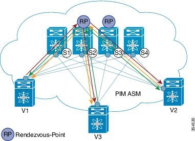
2 つのマルチキャスト ランデブーポイント(S2 および S3)が設定されます。2 番目のランデブーポイントは、ロード シェアリングと冗長性のために追加されます。エニーキャスト RP は、PIM ASM トポロジ イメージに表示されます。エニーキャスト RP は、2 つのランデブーポイント間の冗長性とロード シェアリングを保証します。エニーキャスト RP を使用するには、RP として機能する複数のスパインが同じ IP アドレス(エニーキャスト RP アドレス)を共有します。一方、各
RP には、RP として機能するすべてのスパイン間の送信元に関する情報を同期するために、RP 用に設定された固有の IP アドレスがあります。
Leaf-Switch-V1# show ip pim rp

PIM RP Status Information for VRF "default"
BSR disabled
Auto-RP disabled
BSR RP Candidate policy: None
BSR RP policy: None
Auto-RP Announce policy: None
Auto-RP Discovery policy: None

RP: 198.51.100.220, (0), uptime: 03:17:43, expires: never,
  priority: 0, RP-source: (local), group ranges:
      224.0.0.0/9
Leaf-Switch-V1# show ip pim interface

PIM Interface Status for VRF "default"
Ethernet1/1, Interface status: protocol-up/link-up/admin-up
  IP address: 209.165.201.14, IP subnet: 209.165.201.14/31
  PIM DR: 209.165.201.12, DR's priority: 1
  PIM neighbor count: 1
  PIM hello interval: 30 secs, next hello sent in: 00:00:11
  PIM neighbor holdtime: 105 secs
  PIM configured DR priority: 1
  PIM configured DR delay: 3 secs
  PIM border interface: no
  PIM GenID sent in Hellos: 0x33d53dc1
  PIM Hello MD5-AH Authentication: disabled
  PIM Neighbor policy: none configured
  PIM Join-Prune inbound policy: none configured
  PIM Join-Prune outbound policy: none configured
  PIM Join-Prune interval: 1 minutes
  PIM Join-Prune next sending: 1 minutes
  PIM BFD enabled: no
  PIM passive interface: no
  PIM VPC SVI: no
  PIM Auto Enabled: no
  PIM Interface Statistics, last reset: never
    General (sent/received):
      Hellos: 423/425 (early: 0), JPs: 37/32, Asserts: 0/0
      Grafts: 0/0, Graft-Acks: 0/0
      DF-Offers: 4/6, DF-Winners: 0/197, DF-Backoffs: 0/0, DF-Passes: 0/0
    Errors:
      Checksum errors: 0, Invalid packet types/DF subtypes: 0/0
      Authentication failed: 0
      Packet length errors: 0, Bad version packets: 0, Packets from self: 0
      Packets from non-neighbors: 0
          Packets received on passiveinterface: 0
      JPs received on RPF-interface: 0
      (*,G) Joins received with no/wrong RP: 0/0
      (*,G)/(S,G) JPs received for SSM/Bidir groups: 0/0
      JPs filtered by inbound policy: 0
      JPs filtered by outbound policy: 0
loopback0, Interface status: protocol-up/link-up/admin-up
  IP address: 209.165.201.20, IP subnet: 209.165.201.20/32
  PIM DR: 209.165.201.20, DR's priority: 1
  PIM neighbor count: 0
  PIM hello interval: 30 secs, next hello sent in: 00:00:07
  PIM neighbor holdtime: 105 secs
  PIM configured DR priority: 1
  PIM configured DR delay: 3 secs
  PIM border interface: no
  PIM GenID sent in Hellos: 0x1be2bd41
  PIM Hello MD5-AH Authentication: disabled
  PIM Neighbor policy: none configured
  PIM Join-Prune inbound policy: none configured
  PIM Join-Prune outbound policy: none configured
  PIM Join-Prune interval: 1 minutes
  PIM Join-Prune next sending: 1 minutes
  PIM BFD enabled: no
  PIM passive interface: no
  PIM VPC SVI: no
  PIM Auto Enabled: no
  PIM Interface Statistics, last reset: never
    General (sent/received):
      Hellos: 419/0 (early: 0), JPs: 2/0, Asserts: 0/0
      Grafts: 0/0, Graft-Acks: 0/0
      DF-Offers: 3/0, DF-Winners: 0/0, DF-Backoffs: 0/0, DF-Passes: 0/0
    Errors:
      Checksum errors: 0, Invalid packet types/DF subtypes: 0/0
      Authentication failed: 0
      Packet length errors: 0, Bad version packets: 0, Packets from self: 0
     Packets from non-neighbors: 0
          Packets received on passiveinterface: 0
      JPs received on RPF-interface: 0
      (*,G) Joins received with no/wrong RP: 0/0
      (*,G)/(S,G) JPs received for SSM/Bidir groups: 0/0
      JPs filtered by inbound policy: 0
      JPs filtered by outbound policy: 0
Leaf-Switch-V1# show ip pim neighbor

PIM Neighbor Status for VRF "default"

Neighbor       Interface      Uptime    Expires    DR         Bidir-        BFD
                                                   Priority   Capable       State
10.10.100.100  Ethernet1/1    1w1d      00:01:33   1          yes           n/a
コマンドの詳細なリストについては、 『Configuration and Command Reference』ガイドを参照してください。
イメージのトポロジの一部について、設定タスクと対応する show コマンドの出力が表示されます。たとえば、リーフ スイッチと接続されたスパイン スイッチの設定例が示されている場合、その設定の show コマンド出力には対応する設定のみが表示されます。
リーフ スイッチ V1 の設定
リーフスイッチ V1 でのファントム ランデブーポイント アソシエーション
(config) #
feature pim
ip pim rp-address 10.254.254.1 group-list 227.2.2.0/26 bidir
ip pim rp-address 10.254.254.65 group-list 227.2.2.64/26 bidir
リーフ スイッチ V1 のループバック インターフェイス PIM 設定
(config) #
interface loopback 0
  ip address 10.1.1.54/32
  ip pim sparse-mode
リーフ スイッチ V1 の IP アンナンバード P2P インターフェイス設定
(config) #
interface Ethernet 1/1
  no switchport
  mtu 9192
  medium p2p
  ip unnumbered loopback 0
  ip pim sparse-mode

interface Ethernet 2/2
  no switchport
  mtu 9192
  medium p2p
  ip unnumbered loopback 0
  ip pim sparse-mode
Cisco Nexus 5600 シリーズ スイッチには 9192 の MTU を使用します。
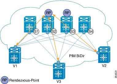
ランデブーポイントの設定(RP として動作する 2 つのスパイン スイッチ S2 および S3)
スパイン スイッチ S2 でのファントム RP の使用
(config) #
feature pim
ip pim rp-address 10.254.254.1 group-list 227.2.2.0/26 bidir
ip pim rp-address 10.254.254.65 group-list 227.2.2.64/26 bidir
スパイン スイッチ S2/RP1 のループバック インターフェイス PIM 設定(RP)
(config) #
interface loopback 0
  ip address 10.1.1.53/32
  ip pim sparse-mode


 フィードバック