Cisco APIC NX-OS スタイル コマンドライン インターフェイス コンフィギュレーション ガイド
偏向のない言語
この製品のマニュアルセットは、偏向のない言語を使用するように配慮されています。このマニュアルセットでの偏向のない言語とは、年齢、障害、性別、人種的アイデンティティ、民族的アイデンティティ、性的指向、社会経済的地位、およびインターセクショナリティに基づく差別を意味しない言語として定義されています。製品ソフトウェアのユーザーインターフェイスにハードコードされている言語、RFP のドキュメントに基づいて使用されている言語、または参照されているサードパーティ製品で使用されている言語によりドキュメントに例外が存在する場合があります。シスコのインクルーシブランゲージに対する取り組みの詳細は、こちらをご覧ください。
翻訳について
このドキュメントは、米国シスコ発行ドキュメントの参考和訳です。リンク情報につきましては、日本語版掲載時点で、英語版にアップデートがあり、リンク先のページが移動/変更されている場合がありますことをご了承ください。あくまでも参考和訳となりますので、正式な内容については米国サイトのドキュメントを参照ください。
- Updated:
- 2017年1月10日
章のタイトル: レイヤ 3 外部接続の設定
- レイヤ 3 外部接続の設定のモードについて
- レイヤ 3 外部接続の設定
- インターフェイスとスタティック ルーティングの設定
- OSPF の設定
- BGP の設定
- EIGRP の設定
- ルート マップの設定
- 双方向ルート転送(BFD)の設定
- レイヤ 3 マルチキャストの設定
- 外部 L3 EPG の設定
- 名前付きモードを使用したレイヤ 3 外部接続の設定
- ファブリック WAN 経由のレイヤ 3 EVPN サービス
- マルチポッド ファブリックの設定
レイヤ 3 外部接続の設定のモードについて
APIC は設定のための複数のユーザ インターフェイス(UI)をサポートしているので、1 つの UI を使用して設定を作成し、その後、別の UI を使用して設定を変更する場合は、予期しないインタラクションが潜んでいます。ここでは、さらに他の APIC のユーザ インターフェイスを使用した可能性がある場合、APIC NX-OS スタイルの CLI を使用してレイヤ 3 外部接続を設定するための考慮事項を説明します。
APIC NX-OS スタイルの CLI を使用してレイヤ 3 外部接続を設定する場合、次の 2 つのモードを選択することができます。
-
基本(または暗黙的)モードは、基本 GUI との互換性はありますが、拡張 GUI または API との互換性はありません。
-
名前付き(または明示的)モードは、拡張 GUI および API との互換性はありますが、基本 GUI との互換性はありません。
いずれの場合も、設定は互換性がない UI では読み取り専用であると考えてください。
モードの違いについて
両方のモードでは、構成設定は、API の l3extOut クラスのインスタンスである内部コンテナ オブジェクト、「L3 Outside」(または「L3Out」)内で定義されます。2 つのモード間の主な違いは、このコンテナ オブジェクト インスタンスの命名にあります。
-
基本:基本モードでは、コンテナの命名は暗黙的で、CLI コマンドには表示されません。CLI は、これらのオブジェクトを内部的に作成し保持します。
-
名前付き:名前付きモードでは、命名はユーザが指定します。名前付きモードの CLI コマンドには、さらに l3Out フィールドがあります。名前付き L3Out 設定を正しく使用し障害を回避するためには、ユーザが外部レイヤ 3 用の API オブジェクト モデルを理解する必要があります。
 (注) |
名前付きモード セクションを使用したレイヤ 3 外部接続の設定の手順を除き、この章では、基本モード手順を説明します。 |
注意事項および制約事項
-
同じ APIC では、両方のモードを、次の制限でレイヤ 3 外部接続を設定するために一緒に使用することができます。テナント VRF、およびリーフの特定の組み合わせのレイヤ 3 外部接続設定は、2 つのモードのいずれかを介してのみ実行できます。
-
特定のテナント VRF の場合、外部 L3 EPG を配置できるポリシー ドメインは、名前付きモードまたは基本モードのいずれかになります。推奨する設定方式は、特定のテナント VRF が、レイヤ 3 外部接続用に展開されたすべてのノード全体で、特定のテナント VRF の組み合わせに対して 1 つのモードだけを使用することです。モードは、異なるテナントまたは異なる VRF 全体で変えることができ、制限は適用されません。
-
外部レイヤ 3 機能は、次の例外を除いて、両方の設定モードでサポートされます。
-
基本モード CLI 手順によって暗黙的に作成されるレイヤ 3 外部ネットワーク オブジェクト(l3extOut)は、「__ui_」で始まる名前で識別され、拡張 GUI で読み取り専用としてマークされます。CLI は、インターフェイス、プロトコル、ルート マップ、EPG などの機能で、これらの外部 L3 ネットワークを分割します。API を介して実行される設定変更は、この構造を破棄することができ、CLI を介してさらなる変更を防ぐことができます。
レイヤ 3 外部接続の設定
外部ネットワークへのレイヤ 3(L3)ルーティング接続の設定は、次のコンポーネントで構成されています。
-
インターフェイス:レイヤ 3 ポートの設定インターフェイス、サブインターフェイス、外部ルータに接続するために使用される外部 SVI。
-
ルーティング プロトコルの設定:CLI は静的ルート、BGP、OSPF、EIGRP プロトコル設定をサポートします。
-
ルート マップ制御:ルート マップは、prefixes/BD パブリック サブネットと一致させ、ルーティング制御ポリシーを適用するために使用されます。ルート マップが作成されると、「in」(BGP)、「out」(BGP、OSPF、EIGRP)などの、方向のルーティング プロトコルと関連付けることができます。
インターフェイス、ルート プロトコル、およびルートマップに関する設定は、構成リーフの設定モードでリーフ スイッチ単位で保持されます。
-
L3 外部 EPG:コントラクトと QoS ポリシーを適用するためのエンドポイント グループに分類されるテナント VRF の外部サブネットのリスト。L3 外部 EPG(プレフィックス EPG ともいいます)には、他の外部 L3 EPG およびアプリケーション EPG とコントラクトを持つことができます。L3 外部 EPG 設定はテナント設定で保持されます。L3 外部 EPG は、VRF が設定されているノードのサブセットに展開できます。
レイヤ 3 外部接続を設定するための手順は、次のように要約できます。
インターフェイスとスタティック ルーティングの設定
テナントおよび VRF を設定します。
例
次に、外部接続用にレイヤ 3 ポートを導入する例を示します。
apic1# configure
apic1(config)# leaf 101
apic1(config-leaf)# vrf context tenant exampleCorp vrf v1
apic1(config-leaf-vrf)# router-id 1.2.3.4
apic1(config-leaf-vrf)# ip route 21.1.1.1/32 32.1.1.1
apic1(config-leaf-vrf)# ipv6 route 5001::1/128 6002::1 preferred
apic1(config-leaf-vrf)# exit

apic1(config-leaf)# interface eth 1/1
apic1(config-leaf-if)# vlan-domain member dom1
apic1(config-leaf-if)# no switchport
apic1(config-leaf-if)# vrf member tenant exampleCorp vrf v1
apic1(config-leaf-if)# ip address 10.1.1.1/24
apic1(config-leaf-if)# ip address 11.1.1.1/24 secondary
apic1(config-leaf-if)# ipv6 address 2001::1/64 preferred
apic1(config-leaf-if)# ipv6 link-local fe80::1
apic1(config-leaf-if)# mac-address 00:44:55:66:55::01
apic1(config-leaf-if)# mtu 4470
次に、外部接続用にレイヤ 3 サブインターフェイス ポートを設定する例を示します。この例では、サブインターフェイス ID(1/2.100 の「100」)は実際には ID ではなく VLAN のカプセル化です。サブインターフェイスでは、レイヤ 3 ポートでサポートされるすべてのプロパティを同様に利用できます。
apic1# configure
apic1(config)# leaf 101
    # SAME VRF CONTEXT CONFIGURATION AS PREVIOUS EXAMPLE

apic1(config-leaf)# interface eth 1/2.100
apic1(config-leaf-if)# vrf member tenant exampleCorp vrf v1
    # SAME L3 PROPERTIES CONFIGURATION AS PREVIOUS EXAMPLE
次に、外部接続用にスイッチ仮想インターフェイス(SVI)を設定する方法を示します。各外部 SVI は SVI ID で示されるカプセル化 VLAN によって一意に識別されます。
apic1# configure
apic1(config)# leaf 101
    # SAME VRF CONTEXT CONFIGURATION AS PREVIOUS EXAMPLE

apic1(config-leaf)# interface vlan 200
apic1(config-leaf-if)# vrf member tenant exampleCorp vrf v1
apic1(config-leaf-if)# ip address 13.1.1.1/24

    # HOW TO ATTACH A PORT TO THE EXTERNAL SVI:
apic1(config)# leaf 101
apic1(config-leaf)# interface eth 1/4
apic1(config-leaf-if)# vlan-domain member dom1
apic1(config-leaf)# switchport trunk allowed vlan 10 tenant exampleCorp external-svi

    # HOW TO ATTACH A PORT CHANNEL TO THE EXTERNAL SVI:
apic1(config)# leaf 102
apic1(config-leaf)# interface port-channel po1
apic1(config-leaf-if)# vlan-domain member dom1
apic1(config-leaf)# switchport trunk allowed vlan 10 tenant exampleCorp external-svi

    # HOW TO ATTACH A VIRTUAL PORT CHANNEL (vPC) TO THE EXTERNAL SVI:
apic1(config)# vpc context leaf 101 102
apic1(config-leaf)# interface vpc vpc103
apic1(config-leaf-if)# vlan-domain member dom1
apic1(config-leaf)# switchport trunk allowed vlan 10 tenant exampleCorp external-svi
(注) |
外部 SVI は参加ノードごとに設定する必要があります。これにより、同じ SVI でノードごとに異なる IP アドレスを設定することができます。vPC が外部 SVI の一部である場合、参加している vPC ピアごとに SVI を個別に作成する必要があり、SVI ごとに異なる IP アドレスを指定することができます。 |
OSPF の設定
OSPF はエリアで次のいずれかのモードで動作できます。
-
OSPF がノードでテナント VRF の主要なルーティング プロトコルとして使用される場合、OSPF は OSPF エリアで設定されたルートマップに定義されているルートをインポートおよびエクスポートします。ルートマップにはエクスポート ルートが含まれます。
-
OSPF が BGP の接続プロトコルとして使用される場合、OSPF は BGP セッションの送信元として使用されるループバック アドレスをアドバタイズします。ループバック ID ではなくループバック IP アドレスが使用されることに注意してください。この場合、OSPF に依存している BGP セッションは update-source コマンドで同じループバック IP アドレスを使用します。
OSPF と OSPFv3 に個別の設定は必要ありません。ルータ OSPF モードは OSPF で実行されているエリアでは暗黙的に OSPFv2 と OSPFv3 の両方を処理します。
OSPF セッションは、次に示す、リーフのすべてのタイプのレイヤ 3 インターフェイスでサポートされます。
例
apic1# configure
apic1(config)# leaf 101
apic1(config-leaf)# router ospf default
apic1(config-leaf-ospf)# vrf member tenant exampleCorp vrf v100
apic1(config-leaf-ospf-vrf)# area 0 nssa
apic1(config-leaf-ospf-vrf)# area 17 stub
apic1(config-leaf-ospf-vrf)# area 17 default-cost 20
apic1(config-leaf-ospf-vrf)# area 17 route-map ospf-to-eigrp out
apic1(config-leaf-ospf-vrf)# area 17 loopback 192.0.20.11/32
apic1(config-leaf-ospf-vrf)# inherit ipv4 ospf vrf-policy vrfTemplate2
apic1(config-leaf-ospf-vrf)# summary-address 182.1.20.0/24
apic1(config-leaf-ospf-vrf)# area 17 range 192.0.20.0/24 cost 20
apic1(config-leaf-ospf-vrf)# exit
apic1(config-leaf-ospf)# exit
apic1(config-leaf)# interface eth 1/3
apic1(config-leaf-if)# ip router ospf default area 17
apic1(config-leaf-if)# ip ospf inherit interface-policy ifPolicy3 tenant exampleCorp
apic1(config-leaf-if)# ip ospf prefix-suppression enable
apic1(config-leaf-if)# ip ospf passive-interface
apic1(config-leaf-if)# ip ospf authentication md5
apic1(config-leaf-if)# ip ospf authentication-key c1$c0123
OSPF VRF とインターフェイス テンプレートの作成
例
次に、VRF テンプレートおよびインターフェイス テンプレートを設定する例を示します。
apic1# configure
apic1(config)# leaf 101

    # CONFIGURING THE VRF TEMPLATE:
apic1(config-leaf)# template ospf vrf-policy vrfTemplate3 tenant exampleCorp
apic1(config-vrf-policy)# timers throttle lsa 200 10000 45000
apic1(config-vrf-policy)# timers lsa-group-pacing 240
apic1(config-vrf-policy)# timers lsa-arrival 1000
apic1(config-vrf-policy)# timers throttle spf 5 1000 90000
apic1(config-vrf-policy)# auto-cost reference-bandwidth 1000
apic1(config-vrf-policy)# distance 200
apic1(config-vrf-policy)# maximum-paths 8
apic1(config-vrf-policy)# graceful-restart helper-disable
apic1(config-vrf-policy)# prefix-suppression
apic1(config-vrf-policy)# name-lookup
apic1(config-vrf-policy)# exit

    # CONFIGURING THE INTERFACE TEMPLATE:
apic1(config-leaf)# template ospf interface-policy ifTemplate5 tenant exampleCorp
apic1(config-ospf-if-policy)# advertise-subnet
apic1(config-ospf-if-policy)# cost 300
apic1(config-ospf-if-policy)# dead-interval 60
apic1(config-ospf-if-policy)# hello-interval 10
apic1(config-ospf-if-policy)# mtu-ignore
apic1(config-ospf-if-policy)# network p2p
apic1(config-ospf-if-policy)# passive-interface
apic1(config-ospf-if-policy)# priority 4
apic1(config-ospf-if-policy)# retransmit-interval 5
apic1(config-ospf-if-policy)# transmit-delay 2
BGP の設定
例
apic1# configure
apic1(config)# pod 1
apic1(config-pod)# bgp fabric
apic1(config-pod-bgp)# asn 100
apic1(config-pod-bgp)# route-reflector spine 105
BGP アドレス ファミリとカウンタを設定します。
BGP アドレス ファミリとタイマー テンプレートの作成
例
次に、BGP タイマー テンプレートとアドレス ファミリ テンプレートを作成する例を示します。
apic1# configure
apic1(config)# leaf 101
# CREATE A TIMER TEMPLATE
apic1(config-leaf)# template bgp timers bgpTimers tenant exampleCorp
This template will be available on all leaves
where tenant exampleCorp has a VRF deployment
apic1(config-bgp-timers)# timers bgp 10 20
apic1(config-bgp-timers)# graceful-restart stalepath-time 3600
apic1(config-bgp-timers)# exit
# CREATE AN ADDRESS FAMILY TEMPLATE
apic1(config-leaf)# template bgp address-family bgpAf1 tenant bgp_t1
This template will be available on all leaves where tenant exampleCorp has a VRF deployment
apic1(config-bgp-af)# distance 250 240 230
apic1(config-bgp-af)# exit
apic1(config-leaf)# exit
BGP アドレス ファミリとタイマーの設定
BGP アドレス ファミリのテンプレートとタイマーのテンプレートを作成します。
例
この例では、BGP タイマー設定、IPv4 および IPv6 アドレス ファミリを継承する方法を示します。
apic1# configure
apic1(config)# leaf 101
apic1(config-leaf)# router bgp 100
apic1(config-bgp)# vrf member tenant exampleCorp vrf v100
apic1(config-leaf-bgp-vrf)# inherit bgp timer bgpTimers
This template will be inherited on all leaves where VRF v100 has been deployed
apic1(config-leaf-bgp-vrf)# address-family ipv4 unicast
apic1(config-leaf-bgp-vrf-af)# inherit bgp address-family ipv4-af-pol
This template will be inherited on all leaves where VRF v100 has been deployed
apic1(config-leaf-bgp-vrf-af)# exit
apic1(config-leaf-bgp-vrf)# address-family ipv6 unicast
apic1(config-leaf-bgp-vrf-af)# inherit bgp address-family ipv6-af-pol
This template will be inherited on all leaves where VRF v100 has been deployed
apic1(config-leaf-bgp-vrf-af)# exit
apic1(config-leaf-bgp-vrf)# exit
apic1(config-leaf)# exit
BGP ネイバーの設定
次の表に、この時点で設定できるインターフェイス設定を示します。
| コマンド |
目的 |
|---|---|
| allow-self-as |
as-path を、その中に自身の AS を含めて受け入れます |
| allowed-self-as-count count |
ローカル アクセス サービス ネットワークの発生件数を指定します |
| disable-connected-check |
直接接続されたピアのチェックをディセーブルにします |
| disable-peer-as-check |
アドバタイジング中のピア AS 番号のチェックをディセーブルにします |
| ebgp-multihop count |
リモート ピアにマルチホップ TTL を指定します |
| local-as asn |
BGP ピアのローカルの自律システム設定をします |
| next-hop-self |
ピアリング アドレスをネクストホップとして設定します |
| password password |
ネイバーのパスワードを設定します |
| private-as-control |
AS パスからプライベート ASN を削除します |
| remote-as asn |
ネイバーの自律システム番号を指定します |
| route-map name {in | out} |
ネイバーにルートマップ適用します |
| send-community [extended] |
コミュニティ属性をこのネイバーに送信します |
| update-source vlan vlan-id |
送信元 VLAN インターフェイスを指定します |
| update-source ethernet slot/port |
送信元イーサーネット インターフェイスを指定します |
| update-source loopback ip-address |
送信元ルックバック インターフェイスを指定します |
| weight number |
ルーティング テーブルの BGP 重みを指定します |
例
この例では、IPv4 BGP ネイバーを設定する方法を示します。
apic1# configure
apic1(config)# leaf 101
apic1(config-leaf)# router bgp 100
apic1(config-bgp)# vrf member tenant exampleCorp vrf v100
apic1(config-leaf-bgp-vrf)# aggregate-address 192.0.10.0/24 as-set
apic1(config-leaf-bgp-vrf)# neighbor 192.0.2.229/32
apic1(config-leaf-bgp-vrf-neighbor)# address-family ipv4 unicast
apic1(config-leaf-bgp-vrf-neighbor-af)# maximum-prefix 10 threshold 10 action restart restart-time 10
apic1(config-leaf-bgp-vrf-neighbor-af)# exit
apic1(config-leaf-bgp-vrf-neighbor)# allow-self-as
apic1(config-leaf-bgp-vrf-neighbor)# allowed-self-as-count 2
apic1(config-leaf-bgp-vrf-neighbor)# disable-connected-check
apic1(config-leaf-bgp-vrf-neighbor)# disable-peer-as-check
apic1(config-leaf-bgp-vrf-neighbor)# ebgp-multihop 4
apic1(config-leaf-bgp-vrf-neighbor)# local-as 100
apic1(config-leaf-bgp-vrf-neighbor)# next-hop-self
apic1(config-leaf-bgp-vrf-neighbor)# password abcdef
apic1(config-leaf-bgp-vrf-neighbor)# remote-as 200
apic1(config-leaf-bgp-vrf-neighbor)# send-community extended
apic1(config-leaf-bgp-vrf-neighbor)# update-source vlan 601
apic1(config-leaf-bgp-vrf-neighbor)# update-source ethernet 1/15
apic1(config-leaf-bgp-vrf-neighbor)# update-source loopback 192.0.2.230
Warning: BGP Configuration changed. Please re-configure BGP Password if it was enabled
apic1(config-leaf-bgp-vrf-neighbor)# local-as 100 no-prepend replace-as dual-as
apic1(config-leaf-bgp-vrf-neighbor)# route-map rMapT3 out
apic1(config-leaf-bgp-vrf-neighbor)# weight 2000
apic1(config-leaf-bgp-vrf-neighbor)# private-as-control
apic1(config-leaf-bgp-vrf-neighbor)# exit
apic1(config-leaf-bgp-vrf)# exit
apic1(config-leaf)# exit
この例では、IPv6 BGP ネイバーを設定する方法を示します。
apic1# configure
apic1(config)# leaf 101
apic1(config-leaf)# router bgp 100
apic1(config-bgp)# vrf member tenant exampleCorp vrf v100
apic1(config-leaf-bgp-vrf)# neighbor 2001:80:1:2::229
apic1(config-leaf-bgp-vrf-neighbor)# address-family ipv6 unicast
apic1(config-leaf-bgp-vrf-neighbor-af)# maximum-prefix 100
apic1(config-leaf-bgp-vrf-neighbor-af)# exit
apic1(config-leaf-bgp-vrf-neighbor)# allow-self-as
apic1(config-leaf-bgp-vrf-neighbor)# allowed-self-as-count 2
apic1(config-leaf-bgp-vrf-neighbor)# disable-connected-check
apic1(config-leaf-bgp-vrf-neighbor)# disable-peer-as-check
apic1(config-leaf-bgp-vrf-neighbor)# ebgp-multihop 4
apic1(config-leaf-bgp-vrf-neighbor)# local-as 100
apic1(config-leaf-bgp-vrf-neighbor)# next-hop-self
apic1(config-leaf-bgp-vrf-neighbor)# password abcdef
apic1(config-leaf-bgp-vrf-neighbor)# remote-as 200
apic1(config-leaf-bgp-vrf-neighbor)# send-community extended
apic1(config-leaf-bgp-vrf-neighbor)# update-source vlan 601
apic1(config-leaf-bgp-vrf-neighbor)# update-source ethernet 1/15
apic1(config-leaf-bgp-vrf-neighbor)# update-source loopback 2001:80:1:2::230/128
Warning: BGP Configuration changed. Please re-configure BGP Password if it was enabled
apic1(config-leaf-bgp-vrf-neighbor)# local-as 100 no-prepend replace-as dual-as
apic1(config-leaf-bgp-vrf-neighbor)# route-map rMapT3 out
apic1(config-leaf-bgp-vrf-neighbor)# weight 2000
apic1(config-leaf-bgp-vrf-neighbor)# private-as-control
apic1(config-leaf-bgp-vrf-neighbor)# exit
apic1(config-leaf-bgp-vrf-af)# exit
apic1(config-leaf-bgp-vrf)# exit
apic1(config-leaf)# exit
テナントの範囲によるルート プロファイルの設定
apic1# configure
apic1(config)# leaf 101
apic1(config-leaf)# template route-profile map_eigrp tenant exampleCorp
apic1(config-leaf-template-route-profile)# set tag 200
apic1(config-leaf-template-route-profile)# exit
apic1(config-leaf)# template route-profile map_ospf tenant exampleCorp
apic1(config-leaf-template-route-profile)# set tag 100
apic1(config-leaf-template-route-profile)# exit
この手順で作成されたルート プロファイルのいずれかを使用して、OSPF および EIGRP の BGP の下に再配布ルート プロファイルを設定します。
再配布ルート プロファイルの設定
ルート再配布のテナントの下にルート プロファイル テンプレートを作成します。
この例では、テナントの範囲によるルート プロファイルの作成の例で作成したルート プロファイルを使用して、OSPF および EIGRP の BGP の下に再配布ルート プロファイルを設定します。再配布ルート マップは、すべてのルートを可能(許可)し、ルート制御アクションに関するルート プロファイルを適用します。この例では、すべての EIGRP 学習ルートは、タグ 200 を使用して BGP に再配布され、OSPF ルートは、タグ 100 を使用して BGP に再配布されます。
apic1# configure
apic1(config)# leaf 101
apic1(config-leaf)# router bgp 100
apic1(config-bgp)# vrf member tenant exampleCorp vrf v1
apic1(config-leaf-bgp-vrf)# redistribute eigrp route-map map_eigrp
apic1(config-leaf-bgp-vrf)# redistribute ospf route-map map_ospf
BGP ルート ダンプニングの設定
BGP ルート ダンプニングでは、境界リーフ スイッチ(BLs)に接続されている外部ルータから受信したフラッピング eBGP ルートのファブリックへの伝搬を最小限に抑えます。外部ルータから頻繁にフラッピングするルートは設定された条件に基づいて BLs で抑制され、iBGP ピア(ACI スパイン スイッチ)への再配布が禁止されます。抑制されたルートは設定された時間条件の後で再使用されます。各フラップは eBGP ルートに 1000 のペナルティを科します。フラップのペナルティが定義された抑制限度のしきい値(デフォルトは 2000)に達すると、eBGP ルートは抑制としてマーキングされます。抑制されたルートは他の BGP ピアにはアドバタイズされません。ペナルティは、半減期(デフォルトは 15 分)ごとに半分に減少します。抑制されたルートは、ペナルティが指定された再利用の限度(デフォルトは 750)を下回ると再利用されます。抑制されたルートは、指定された最大抑制時間(最大 45 分間)の間最大限に抑制されます。
apic1# configure
apic1(config)# leaf 101
apic1(config-leaf)# template route-profile damp_rp tenant exampleCorp
apic1(config-leaf-template-route-profile)# set dampening 15 750 2000 60
apic1(config-leaf-template-route-profile)# exit
apic1(config-leaf)# router bgp 100
apic1(config-bgp)# vrf member tenant exampleCorp vrf v100
apic1(config-leaf-bgp-vrf)# neighbor 192.0.2.229/32
apic1(config-leaf-bgp-vrf-neighbor)# address-family ipv4 unicast
apic1(config-leaf-bgp-vrf-neighbor-af)# inherit bgp dampening damp_rp
apic1(config-leaf-bgp-vrf-neighbor-af)# exit
apic1(config-leaf-bgp-vrf)# address-family ipv6 unicast
apic1(config-leaf-bgp-vrf-af)# inherit bgp dampening damp_rp
apic1(config-leaf-bgp-vrf-af)# exit
EIGRP VRF とインターフェイス テンプレートの作成
例
apic1# configure
apic1(config)# leaf 101
# CONFIGURING THE VRF TEMPLATE:
apic1(config-leaf)# template eigrp vrf-policy vrfTemplate3 tenant exampleCorp
This template will be available on all leaves where tenant exampleCorp has a VRF deployment
apic1(config-template-eigrp-vrf-pol)# distance 2 5
apic1(config-template-eigrp-vrf-pol)# maximum-paths 8
apic1(config-template-eigrp-vrf-pol)# metric version 64bit
apic1(config-template-eigrp-vrf-pol)# timers active-time 1
apic1(config-template-eigrp-vrf-pol)# exit
# CONFIGURING THE INTERFACE TEMPLATE:
apic1(config-leaf)# template eigrp interface-policy ifTemplate5 tenant exampleCorp
This template will be available on all leaves where tenant exampleCorp has a VRF deployment
apic1(config-template-eigrp-if-pol)# ip hello-interval eigrp default 5
apic1(config-template-eigrp-if-pol)# ip hold-interval eigrp default 10
apic1(config-template-eigrp-if-pol)# ip next-hop-self eigrp default
apic1(config-template-eigrp-if-pol)# ip passive-interface eigrp default
apic1(config-template-eigrp-if-pol)# ip split-horizon eigrp default
apic1(config-template-eigrp-if-pol)# exit
apic1(config-leaf)# exit
apic1(config)# exit
EIGRP アドレス ファミリとカウンタを設定します。
EIGRP アドレス ファミリとカウンタの設定
例
この例では、EIGRP アドレス ファミリを設定する方法および EIGRP VRF ポリシーを継承する方法を示します。
apic1# configure
apic1(config)# leaf 101
apic1(config-leaf)# router eigrp default
apic1(config-eigrp)# vrf member tenant exampleCorp vrf v100
apic1(config-eigrp-vrf)# autonomous-system 300
apic1(config-eigrp-vrf)# address-family ipv4 unicast
This configuration will affect all leaves where VRF v100 has been deployed
apic1(config-address-family)# distance 2 5
This configuration will affect all leaves where VRF v100 has been deployed
apic1(config-address-family)# maximum-paths 8
This configuration will affect all leaves where VRF v100 has been deployed
apic1(config-address-family)# metric version 64bit
This configuration will affect all leaves where VRF v100 has been deployed
apic1(config-address-family)# timers active-time 1
This configuration will affect all leaves where VRF v100 has been deployed
apic1(config-address-family)# inherit eigrp vrf-policy vrfTemplate3
This template will be inherited on all leaves where VRF v100 has been deployed
apic1(config-address-family)# exit
apic1(config-eigrp-vrf)# exit
apic1(config-eigrp)# exit
EIGRP インターフェイスの設定
例
この例では、EIGRP インターフェイスを設定する方法を示します。
apic1# configure
apic1(config)# leaf 101
apic1(config-leaf)# interface ethernet 1/21
apic1(config-leaf-if)# no switchport
apic1(config-leaf-if)# vlan-domain member dom1
apic1(config-leaf-if)# vrf member tenant exampleCorp vrf v100
apic1(config-leaf-if)# ip address 181.12.12.1/24
apic1(config-leaf-if)# ip router eigrp default
apic1(config-leaf-if)# ip distribute-list eigrp default route-map rMapT5 out
distribute list will be updated on all EIGRP interfaces on node 1021 VRF exampleCorp/v100
apic1(config-leaf-if)# ip hello-interval eigrp default 5
apic1(config-leaf-if)# ip hold-interval eigrp default 10
apic1(config-leaf-if)# ip next-hop-self eigrp default
apic1(config-leaf-if)# ip passive-interface eigrp default
apic1(config-leaf-if)# ip split-horizon eigrp default
apic1(config-leaf-if)# inherit eigrp ip interface-policy ifTemplate5
apic1(config-leaf-if)# ip summary-address eigrp default 172.10.1.0/24
apic1(config-leaf-if)# exit
apic1(config-leaf)# exit
apic1(config)# exit
ルート プロファイルについて
ルート プロファイルは、インポート、エクスポートに使用されるルーティング制御設定のアクションを指定し、ルート マップを再配布します。ルート プロファイル テンプレートは、テナントまたはテナント VRF で定義できます。
テナント スコープ ルート プロファイルの設定
この手順では、BGP ダンプニングとルート再配布の設定に使用されるテナントスコープのルート プロファイルを作成します。
| コマンドまたはアクション | 目的 | |
|---|---|---|
| ステップ 1 | configure 例: apic1# configure |
コンフィギュレーション モードに入ります。 |
| ステップ 2 | leafnode-id 例: apic1(config)# leaf 101 |
設定するリーフを指定します。 |
| ステップ 3 | [no]templateroute-profileprofile-nametenanttenant-name 例: apic1(config-leaf)# template route-profile rp1 tenant exampleCorp |
テナントスコープのルート プロファイルを作成します。 |
| ステップ 4 | [no]setcommunity {regular | extended} value {none | replace | additive} 例: apic1(config-leaf-template-route-profile)# set community extended 20:22 additive |
BGP コミュニティ属性を設定します。 |
| ステップ 5 | [no]setdampeninghalf-lifereusesuppressmax-suppress-time 例: apic1(config-leaf-template-route-profile)# set dampening 15 750 2000 60 |
ルート フラップ ダンプニングの動作を設定します。パラメータは次のとおりです。 |
| ステップ 6 | [no]setlocal-preferencevalue 例: apic1(config-leaf-template-route-profile)# set local-preference 64 |
BGP ローカル プリファレンス値を設定します。範囲は 0 ~ 4294967295 です。 |
| ステップ 7 | [no]setmetricvalue 例: apic1(config-leaf-template-route-profile)# set metric 128 |
宛先ルーティング プロトコルのメトリックを設定します。 |
| ステップ 8 | [no]setmetric-type {type-1 | type-2} 例: apic1(config-leaf-template-route-profile)# set metric-type type-2 |
オプションは次のとおりです。 |
| ステップ 9 | [no]settagname 例: apic1(config-leaf-template-route-profile)# set tag 1111 |
宛先ルーティング プロトコルのタグ値を設定します。name パラメータは符号なし整数です。 |
| ステップ 10 | [no]setweightweight 例: apic1(config-leaf-template-route-profile)# set weight 20 |
宛先ルーティング プロトコルのタグ値を設定します。weight パラメータは符号なし整数です。 |
例
次に、テナントスコープのルート プロファイルを設定する例を示します。
apic1# configure
apic1(config)# leaf 101
apic1(config-leaf)# template route-profile rp1 tenant exampleCorp
This template will be available on all leaves where tenant exampleCorp has a VRF deployment
apic1(config-leaf-template-route-profile)# set community extended 20:22 additive
apic1(config-leaf-template-route-profile)# set dampening 15 750 2000 60
apic1(config-leaf-template-route-profile)# set local-preference 64
apic1(config-leaf-template-route-profile)# set metric 128
apic1(config-leaf-template-route-profile)# set metric-type type-2
apic1(config-leaf-template-route-profile)# set tag 1111
apic1(config-leaf-template-route-profile)# set weight 20
VRF スコープ ルート プロファイルの設定
この手順では、「default-export」および「default-import」を含む VRF スコープのルート プロファイルを作成します。このルート プロファイルは、inherit route-profile コマンドによってルート マップ内のブリッジドメインに「一致」したままブリッジ ドメイン(BD)に接続することができます。
(注) |
VRF スコープ ルート プロファイルは default-export および default-import の値に名前を付け、同じテナント VRF で使用されるエクスポート/インポート ルートマップそれぞれの一致ステートメントに自動的に適用されます。 |
| コマンドまたはアクション | 目的 | |
|---|---|---|
| ステップ 1 | configure 例: apic1# configure |
コンフィギュレーション モードに入ります。 |
| ステップ 2 | leafnode-id 例: apic1(config)# leaf 101 |
設定するリーフを指定します。 |
| ステップ 3 | [no]vrfcontexttenanttenant-namevrfvrf-name 例: apic1(config-leaf)# vrf context tenant exampleCorp vrf vrf1 |
リーフで VRF を有効にし、VRF コンフィギュレーション モードを開始します。 |
| ステップ 4 | [no]templateroute-profileprofile-name 例: apic1(config-leaf-vrf)# template route-profile default-export |
VRF スコープのルート プロファイルを作成します。 |
| ステップ 5 | [no]setcommunity {regular | extended} value {none | replace | additive} 例: apic1(config-leaf-vrf-template-route-profile)# set community extended 20:22 additive |
BGP コミュニティ属性を設定します。 |
| ステップ 6 | [no]setlocal-preferencevalue 例: apic1(config-tenant-vrf-route-profile)# set local-preference 64 |
BGP ローカル プリファレンス値を設定します。範囲は 0 ~ 4294967295 です。 |
| ステップ 7 | [no]setmetricvalue 例: apic1(config-tenant-vrf-route-profile)# set metric 128 |
宛先ルーティング プロトコルのメトリックを設定します。 |
| ステップ 8 | [no]setmetric-type {type-1 | type-2} 例: apic1(config-tenant-vrf-route-profile)# set metric-type type-2 |
オプションは次のとおりです。 |
| ステップ 9 | [no]settagname 例: apic1(config-tenant-vrf-route-profile)# set tag 1111 |
宛先ルーティング プロトコルのタグ値を設定します。name パラメータは符号なし整数です。 |
| ステップ 10 | [no]setweightweight 例: apic1(config-tenant-vrf-route-profile)# set weight 20 |
宛先ルーティング プロトコルのタグ値を設定します。weight パラメータは符号なし整数です。 |
例
次に、VRF スコープのルート プロファイルを設定する例を示します。
apic1# configure
apic1(config)# leaf 101
apic1(config-leaf)# vrf context tenant exampleCorp vrf vrf1
apic1(config-leaf-vrf)# template route-profile default-export
apic1(config-leaf-vrf-template-route-profile)# set community extended 20:22 additive
apic1(config-leaf-vrf-template-route-profile)# set local-preference 64
apic1(config-leaf-vrf-template-route-profile)# set metric 128
apic1(config-leaf-vrf-template-route-profile)# set metric-type type-2
apic1(config-leaf-vrf-template-route-profile)# set tag 1111
apic1(config-leaf-vrf-template-route-profile)# set weight 20
BGP コミュニティとコミュニティ リストについて
BGP コミュニティは、ネットワーク、自律システム、またはあらゆる物理的な境界に関係なく、共通プロパティを共有するルートのグループです。BGP コミュニティ リストは、ルート マップの match 句で使用されるコミュニティ グループを作成するために使用されます。たとえば、コミュニティ リストは、どのルートが受け付けられ、優先され、分散され、アドバタイズされるかを制御することができます。また、コミュニティ リストは、ルートのコミュニティの設定、追加または変更にも使用できます。
BGP コミュニティ リストの作成
通常のコミュニティ リストまたは追加の属性を伝送できる拡張コミュニティ リストを作成できます。どちらのタイプも、さらに 2 つのバリエーションを指定することができます。
-
標準コミュニティ リストは、ウェルノウン コミュニティやコミュニティ番号の指定に使用されます。
-
拡張コミュニティ リストは正規表現によるフィルタ コミュニティに使用されます。正規表現は、コミュニティの照合パターンの指定に使用されます。
拡張標準リストでは、コミュニティが自律システム(AS)の境界を越えて中継されるかどうかをオプションで指定できます。
| コマンドまたはアクション | 目的 | |||||||||||
|---|---|---|---|---|---|---|---|---|---|---|---|---|
| ステップ 1 | configure 例: apic1# configure |
コンフィギュレーション モードに入ります。 |
||||||||||
| ステップ 2 | leaf node-id 例: apic1(config)# leaf 101 |
設定するリーフを指定します。 |
||||||||||
| ステップ 3 | 目的のタイプのコミュニティ リストを作成するには、次のコマンドから選択します。
|
正規表現では、* または + の文字を使用した照合の順序は、最長のコンストラクトが最初になります。入れ子のコンストラクトは外側から内側へと照合されます。連結コンストラクトは左側から順に照合されます。ある正規表現が、1 つの入力文字列の異なる 2 つの部分と一致する可能性がある場合、早く入力された部分が最初に一致します。 |
例
次に、テナント「common」に「CL1」という名前のコミュニティ リストを作成するためにそれぞれを選択した例を示します。
apic1# configure
apic1(config)# leaf 101
apic1(config-leaf)# template community-list standard CL1 65536:20 tenant common
apic1(config-leaf)# template community-list expanded CL1 “50000:[0-9][0-9]_” tenant common
apic1(config-leaf)# template extcommunity-list standard CL1 65536:20 tenant common scope transitive
apic1(config-leaf)# template extcommunity-list expanded CL1 “50000:[0-9][0-9]_” tenant common
ルート マップの作成
ルートマップは、外部ルータにアドバタイズされるブリッジ ドメインのパブリック サブネットを示すため、テナント単位のプレフィックスリストとともに作成されます。また、プレフィックスリストはすべての中継ルートが外部ルータにアドバタイズされるように作成する必要があります。中継ルートのプレフィックスリストは管理者によって設定されます。デフォルトの動作では、外部ルータへの中継ルートのアドバタイズメントはすべて拒否されます。
テナントおよび VRF を設定します。
| コマンドまたはアクション | 目的 | |||
|---|---|---|---|---|
| ステップ 1 | configure 例: apic1# configure |
コンフィギュレーション モードに入ります。 |
||
| ステップ 2 | leafnode-id 例: apic1(config)# leaf 101 |
設定するリーフを指定します。 |
||
| ステップ 3 | [no]vrfcontexttenanttenant-namevrfvrf-name 例: apic1(config-leaf)# vrf context tenant exampleCorp vrf v1 |
ノードのテナント VRF を設定します。 |
||
| ステップ 4 | [no]router-idipv4-address 例: apic1(config-leaf-vrf)# router-id 1.2.3.4 |
(任意) VRF で実行されているルーティング プロトコルに対してルータ ID を割り当てます。ルータ ID を割り当てない場合、各リーフ スイッチに固有の ID が内部で生成されます。 |
||
| ステップ 5 | [no]route-mapname 例: apic1(config-leaf-vrf)# route-map bgpMap |
ルートマップを作成し、ルートマップ コンフィギュレーションを開始します。 |
||
| ステップ 6 | [no]ipprefix-listlist-namepermitprefix/masklen [le {32 | 128}] 例: apic1(config-leaf-vrf-route-map)# ip prefix-list list1 permit 13.13.13.0/24 |
ルートマップにプレフィックスリストを作成します。 |
||
| ステップ 7 | [no]matchprefix-listlist-name 例: apic1(config-leaf-vrf-route-map)# match prefix-list list1 |
作成済みのプレフィックスリストと照合し、一致モードを開始して、プレフィックスリストのルート制御プロファイルを設定します。 |
||
| ステップ 8 | [no]setmetricvalue 例: apic1(config-leaf-vrf-route-map-match)# set metric 128 |
宛先ルーティング プロトコルのメトリックを設定します。 |
||
| ステップ 9 | [no]setmetric-type {type-1 | type-2} 例: apic1(config-leaf-vrf-route-map-match)# set metric-type type-2 |
オプションは次のとおりです。 |
||
| ステップ 10 | [no]setlocal-preferencevalue 例: apic1(config-leaf-vrf-route-map-match)# set local-preference 64 |
BGP ローカル プリファレンス値を設定します。範囲は 0 ~ 4294967295 です。 |
||
| ステップ 11 | [no]setcommunity {regular | extended} value {none | replace | additive} 例: apic1(config-leaf-vrf-route-map-match)# set community extended 20:22 additive |
BGP ルート アップデートのコミュニティ属性を設定します。community-value を aa:nn 形式で指定します。次のいずれかのアクションを指定します。 |
||
| ステップ 12 | [no]settagname 例: apic1(config-leaf-vrf-route-map-match)# set tag 1111 |
宛先ルーティング プロトコルのタグ値を設定します。name パラメータは符号なし整数です。 |
||
| ステップ 13 | [no]setweightvalue 例: apic1(config-leaf-vrf-route-map-match)# set weight 20 |
ルーティング テーブルの BGP 重みを設定します。指定できる value 値は 0 ~ 65536 です。 |
||
| ステップ 14 | exit 例: apic1(config-leaf-vrf-route-map-match)# exit |
ルートマップ コンフィギュレーション モードに戻ります。 |
||
| ステップ 15 | [no]matchbridge-domainbd-name 例: apic1(config-leaf-vrf-route-map)# match bridge-domain bd1 |
ルーティング プロトコルによってパブリック サブネットをエクスポートするため、ブリッジ ドメインと照合します。 |
||
| ステップ 16 | [no]inheritroute-profileprofile-name 例: apic1(config-leaf-vrf-route-map-match)# inherit route-profile default-export |
ブリッジ ドメインのルート プロファイルを設定します。このルート プロファイルは、リーフ、VRF コンテキスト、および VRF の route-profile コマンドを使用してすでに作成されている必要があります。
|
例
次に、ルートマップを作成し、プレフィックスリスト、コミュニティリスト、およびブリッジドメインの追加/一致を行う例を示します。
	   # CREATE A ROUTE-MAP
apic1# configure
apic1(config)# leaf 101
apic1(config-leaf)# vrf context tenant exampleCorp vrf v1
apic1(config-leaf-vrf)# route-map bgpMap

	   # CREATE A PREFIX-LIST
apic1(config-leaf-vrf-route-map)# ip prefix-list list1 permit 13.13.13.0/24
apic1(config-leaf-vrf-route-map)# ip prefix-list list1 permit 14.14.14.0/24

	   # MATCH THE PREFIX-LIST
apic1(config-leaf-vrf-route-map)# match prefix-list list1

	   # CONFIGURE A ROUTE-PROFILE FOR THE PREFIX-LIST
apic1(config-leaf-vrf-route-map-match)# set metric 128
apic1(config-leaf-vrf-route-map-match)# set metric-type type-2
apic1(config-leaf-vrf-route-map-match)# set local-preference 64
apic1(config-leaf-vrf-route-map-match)# set community extended 20:22 additive
apic1(config-leaf-vrf-route-map-match)# set tag 1111
apic1(config-leaf-vrf-route-map-match)# set weight 20
apic1(config-leaf-vrf-route-map-match)# end

	   # CREATE A BRIDGE-DOMAIN
apic1# configure
apic1(config)# tenant exampleCorp
apic1(config-tenant)# vrf context v1
apic1(config-tenant-vrf)# exit
apic1(config-tenant)# bridge-domain bd1
apic1(config-tenant-bd)# vrf member v1
apic1(config-tenant-bd)# exit
apic1(config-tenant)# interface bridge-domain bd1
apic1(config-tenant-interface)# ip address 13.13.13.1/24 scope public
apic1(config-tenant-interface)# exit
apic1(config-tenant)# exit

	   # CREATE A ROUTE-PROFILE FOR THE BRIDGE-DOMAIN
apic1(config)# leaf 101
apic1(config-leaf)# vrf context tenant exampleCorp vrf v1
apic1(config-leaf-vrf)# template route-profile default-export
apic1(config-leaf-vrf-template-route-profile)# set metric 128
apic1(config-leaf-vrf-template-route-profile)# set metric-type type-2
apic1(config-leaf-vrf-template-route-profile)# set local-preference 64
apic1(config-leaf-vrf-template-route-profile)# set community extended 20:22 additive
apic1(config-leaf-vrf-template-route-profile)# set tag 1111
apic1(config-leaf-vrf-template-route-profile)# set weight 20
apic1(config-leaf-vrf-template-route-profile)# exit

	   # MATCH THE BRIDGE-DOMAIN
apic1(config-leaf-vrf)# route-map bgpMap
apic1(config-leaf-vrf-route-map)# match bridge-domain bd1

	   # CONFIGURE A ROUTE-PROFILE FOR THE BRIDGE-DOMAIN
apic1(config-leaf-vrf-route-map-match)# inherit route-profile default-export
ルーティング プロトコルのルートマップの設定
OSPF、BGP、および EIGRP ルーティング プロトコルでは、インポートおよびエクスポートするルートのフィルタ処理にルートマップを使用します。これらのプロトコルを設定するために必要な一般的な手順についてはそれぞれのドキュメント セクションを参照してください。これらのプロトコルでルートマップを設定するには、次のコマンドを使用し、例を参照してください。
| プロトコル |
ルートマップ コマンド |
|---|---|
| BGP |
[no]route-mapmap-name {in | out} |
| OSPF |
[no]areaarea-idroute-mapmap-name {in |out } |
| EIGRP |
[no]ip distribute list defaultroute-mapmap-nameout |
例
次に、BGP、OSPF、および EIGRP でルートマップを設定する例を示します。
    # BGP
apic1# configure
apic1(config)# leaf 101
apic1(config-leaf)# router bgp 100
apic1(config-bgp)# vrf member tenant exampleCorp vrf v1
apic1(config-leaf-bgp-vrf)# neighbor 3.3.3.3
apic1(config-leaf-bgp-vrf-neighbor)# route-map map1 out
apic1(config-leaf-bgp-vrf-neighbor)# route-map map2 in
apic1(config-leaf-bgp-vrf-neighbor)# exit
apic1(config-leaf-bgp-vrf)# exit
apic1(config-bgp)# exit
apic1(config-leaf)# exit

    # OSPF
apic1# configure
apic1(config)# leaf 101
apic1(config-leaf)# router ospf default
apic1(config-leaf-ospf)# vrf member tenant exampleCorp vrf v1
apic1(config-leaf-ospf-vrf)# area 0.0.0.1 route-map map1 out
apic1(config-leaf-ospf-vrf)# area 0.0.0.1 route-map map2 in
apic1(config-leaf-ospf-vrf)# exit
apic1(config-leaf-ospf)# exit
apic1(config-leaf)# exit

    #EIGRP
apic1# configure
apic1(config)# leaf 101
apic1(config-leaf)# interface ethernet 1/3
apic1(config-leaf-if)# vlan-domain member dom1
apic1(config-leaf-if)# no switchport
apic1(config-leaf-if)# vrf member tenant exampleCorp vrf v1
apic1(config-leaf-if)# ip address 13.13.13.13/24
apic1(config-leaf-if)# ip router eigrp default
apic1(config-leaf-if)# ip distribute-list eigrp default route-map map1 out
apic1(config-leaf-if)# exit
apic1(config-leaf)# exit
エクスポート マップ(インター VRF ルート リーク)の設定
| コマンドまたはアクション | 目的 | |
|---|---|---|
| ステップ 1 | configure 例: apic1# configure |
コンフィギュレーション モードに入ります。 |
| ステップ 2 | leafnode-id 例: apic1(config)# leaf 101 |
設定するリーフを指定します。 |
| ステップ 3 | [no]vrfcontexttenanttenant-namevrfvrf-name 例: apic1(config-leaf)# vrf context tenant exampleCorp vrf v1 |
ノードのテナント VRF を設定します。 |
| ステップ 4 | [no]exportmapmap-name 例: apic1(config-leaf-vrf)# export map shared-route-map1 |
この VRF からコンシューマ VRF に(リーク)ルートをエクスポートするようこの VRF でルートマップを設定します。 |
例
次に、ルートマップを作成およびエクスポートする例を示します。
    # CREATE A ROUTE-MAP
apic1# configure
apic1(config)# leaf 101
apic1(config-leaf)# vrf context tenant exampleCorp vrf v1
apic1(config-leaf-vrf)# router-id 1.2.3.4
apic1(config-leaf-vrf)# route-map shared-route-map1
apic1(config-leaf-vrf-route-map)# ip prefix-list list1 permit 13.13.13.0/24
apic1(config-leaf-vrf-route-map)# match prefix-list list1
apic1(config-leaf-vrf-route-map-match)# contract provider prov1
apic1(config-leaf-vrf-route-map-match)# exit
apic1(config-leaf-vrf-route-map)# exit
apic1(config-leaf-vrf)# exit
apic1(config-leaf)# exit

    # EXPORT THE ROUTE-MAP
apic1# configure
apic1(config)# leaf 101
apic1(config-leaf)# vrf context tenant exampleCorp vrf v1
apic1(config-leaf-vrf)# export map shared-route-map1
BFD について
双方向フォワーディング検出(BFD)は、メディア タイプ、カプセル化、トポロジ、およびルーティング プロトコルのために短時間での転送パス障害検出を提供するために設計された検出プロトコルです。BFD を使用することで、さまざまなプロトコルの Hello メカニズムにより、変動速度ではなく一定速度で転送パス障害を検出できます。BFD はプロファイリングおよびプランニングを簡単にし、再コンバージェンス時間の一貫性を保ち、予測可能にします。
双方向フォワーディング検出(BFD)を使用して、ピアリング ルータの接続をサポートするように設定された ACI ファブリック境界リーフ スイッチ間の転送パスのサブセカンド障害検出時間を提供します。
BFD グローバルの設定
デバイスのすべての BFD セッションの BFD セッション パラメータを設定できます。BFD セッション パラメータは、スリーウェイ ハンドシェイクの BFD ピア間でネゴシエートされます。
グローバル BFD を設定するには、次の手順を実行します。
| コマンドまたはアクション | 目的 | |
|---|---|---|
| ステップ 1 | configure 例: apic1# configure |
コンフィギュレーション モードに入ります。 |
| ステップ 2 | [no]templatebfd {ip | ipv6} global-policy-name 例: apic1(config)# template bfd ip bfd_global |
BFD ポリシー テンプレートを作成します。 |
| ステップ 3 | [no]echo-addressip-address 例: apic1(config-bfd)# echo-address 192.0.20.123 apic1(config-bfd)# echo-address 34::1/64 |
BFD エコー パケットの送信元アドレスとして使用する IP アドレスを指定します。 |
| ステップ 4 | [no]slow-timermilliseconds 例: apic1(config-bfd)# slow-timer 2000 |
エコー機能で使用される slow timer を設定します。この値はエコー機能がイネーブルの場合、BFD が新しいセッションを開始する速度および非同期セッションが BFD 制御パケットに使用する速度を決定します。slow-timer 値は新しい制御パケット間隔として使用されますが、エコー パケットは設定された BFD 間隔を使用します。エコー パケットはリンク障害検出に使用されますが、低速の制御パケットは BFD セッションを維持します。指定できる範囲は 1000 ~ 30000 ミリ秒です。 |
| ステップ 5 | [no]min-txmilliseconds 例: apic1(config-bfd)# min-tx 100 |
このデバイスが BFD Hello メッセージを送信する間隔を指定します。有効値は 50 ~ 999 ミリ秒です。 |
| ステップ 6 | [no]min-rxmilliseconds 例: apic1(config-bfd)# min-rx 70 |
このデバイスが別の BFD デバイスからの BFD Hello メッセージを受け付ける最小間隔を指定します。有効値は 50 ~ 999 ミリ秒です。 |
| ステップ 7 | [no]multiplierpolicy-name 例: apic1(config-bfd)# multiplier 3 |
転送パスの障害を検出するまでに喪失した、別の BFD デバイスからの BFD Hello メッセージの数を指定します。指定できる範囲は 1 ~ 50 です。 |
| ステップ 8 | [no]echo-rx-intervalpolicy-name 例: apic1(config-bfd)# echo-rx-interval 500 |
このシステムがサポートできる受信 BFD エコー パケット間の最小間隔を指定します。有効値は 50 ~ 999 ミリ秒です。 |
| ステップ 9 | exit 例: apic1(config-bfd)# exit |
グローバル コンフィギュレーション モードに戻ります。 |
| ステップ 10 | [no]templateleaf-policy-groupleaf-policy-name 例: apic1(config)# template leaf-policy-group leaf_pg1 |
アクセス スリーフ ポリシー グループを設定します。 |
| ステップ 11 | [no]inheritbfd {ip | ipv6} global-policy-name 例: apic1(config-leaf-policy-group)# inherit bfd ip bfd_global |
以前作成したグローバル ポリシーを継承します。 |
| ステップ 12 | exit 例: apic1(config-leaf-policy-group)# exit |
グローバル コンフィギュレーション モードに戻ります。 |
| ステップ 13 | [no]leaf-profileleaf-profile-name 例: apic1(config)# leaf-profile leaf_profile1 |
リーフ プロファイルを設定します。 |
| ステップ 14 | [no]leaf-groupleaf-group-name 例: apic1(config-leaf-profile)# leaf-group leaf_group1 |
リーフ スイッチのグループを作成または指定します。 |
| ステップ 15 | [no]leaf-policy-groupleaf-policy-name 例: apic1(config-leaf-group)# leaf-policy-group leaf_pg1 |
リーフ スイッチに関連付けられる、以前作成したリーフ ポリシー グループを指定します。 |
| ステップ 16 | [no]leafleaf-range 例: apic1(config-leaf-group)# leaf 101-102 |
リーフ スイッチ グループに 1 つ以上のリーフ スイッチを追加します。 |
例
この例では、グローバル BFD を設定し、リーフ スイッチのグループに適用する方法を示します。
    # CONFIGURE BFD GLOBAL POLICIES
apic1# configure
apic1(config)# template bfd ip bfd_global
apic1(config-bfd)# echo-address 192.0.20.123
apic1(config-bfd)# slow-timer 2000
apic1(config-bfd)# min-tx 100
apic1(config-bfd)# min-rx 70
apic1(config-bfd)# multiplier 3
apic1(config-bfd)# echo-rx-interval 500
apic1(config-bfd)# exit

    # CONFIGURE AN ACCESS LEAF POLICY GROUP AND INHERIT BFD GLOBAL POLICIES
apic1(config)# template leaf-policy-group leaf_pg1
apic1(config-leaf-policy-group)# inherit bfd ip bfd_global
apic1(config-leaf-policy-group)# exit

    # CONFIGURE A LEAF GROUP AND ASSOCIATE THE LEAF POLICY GROUP
apic1(config)# leaf-profile leaf_profile1
apic1(config-leaf-profile)# leaf-group leaf_group1
apic1(config-leaf-group)# leaf-policy-group leaf_pg1
apic1(config-leaf-group)# leaf 101-102
BFD インターフェイス オーバーライド ポリシーの設定
明示的な BFD を設定できる、3 つのサポート対象のインターフェイス(ルーテッド L3 インターフェイス、外部インターフェイス SVI とルーテッド サブインターフェイス)があります。グローバル コンフィギュレーションを使用しないで、さらに特定のインターフェイスの明示的な設定をしたい場合、特定のスイッチまたは一連のすべてのインターフェイスに適用される独自のグローバル コンフィギュレーションを作成できます。特定のインターフェイス上の特定のスイッチの粒度がさらに必要な場合、このインターフェイス オーバーライド設定を使用する必要があります。
テナントはすでに作成されています。
| コマンドまたはアクション | 目的 | |
|---|---|---|
| ステップ 1 | configure 例: apic1# configure |
コンフィギュレーション モードに入ります。 |
| ステップ 2 | tenanttenant-name 例: apic1(config)# tenant exampleCorp |
設定するテナントを指定します。 |
| ステップ 3 | vrfcontextvrf-name 例: apic1(config-tenant)# vrf context vrf1 |
テナントと VRF を関連付けます。 |
| ステップ 4 | exit 例: apic1(config-tenant-vrf)# exit |
テナント コンフィギュレーション モードに戻ります。 |
| ステップ 5 | exit 例: apic1(config-tenant)# exit |
グローバル コンフィギュレーション モードに戻ります。 |
| ステップ 6 | leafnode-id 例: apic1(config)# leaf 101 |
設定するリーフを指定します。 |
| ステップ 7 | [no]vrfcontexttenanttenant-namevrfvrf-name 例: apic1(config-leaf)# vrf context tenant exampleCorp vrf vrf1 |
ノードのテナント VRF を設定します。 |
| ステップ 8 | exit 例: apic1(config-leaf-vrf)# exit |
リーフ コンフィギュレーション モードに戻ります。 |
| ステップ 9 | [no]interfacetype 例: apic1(config-leaf)# interface eth 1/18 |
インターフェイス コンフィギュレーション モードを開始します。 |
| ステップ 10 | [no]vrfmembertenanttenant-namevrfvrf-name 例: apic1(config-leaf-if)# vrf member tenant exampleCorp vrf vrf1 |
|
| ステップ 11 | exit 例: apic1(config-leaf-if)# exit |
リーフ コンフィギュレーション モードに戻ります。 |
| ステップ 12 | [no]templatebfdtemplate-nametenanttenant-name 例: apic1(config-leaf)# template bfd bfdIfPol1 tenant exampleCorp |
BFD インターフェイス ポリシーを設定します。 |
| ステップ 13 | [no]echo-modeenable 例: apic1(config-template-bfd-pol)# echo-mode enable |
BFD 制御パケットに加えて BFD エコー パケットを送信をイネーブルまたはディセーブルにします。 |
| ステップ 14 | [no]echo-rx-intervalpolicy-name 例: apic1(config-template-bfd-pol)# echo-rx-interval 500 |
このシステムがサポートできる受信 BFD エコー パケット間の最小間隔を指定します。有効値は 50 ~ 999 ミリ秒です。 |
| ステップ 15 | [no]min-txmilliseconds 例: apic1(config-template-bfd-pol)# min-tx 100 |
このデバイスが、BFD hello メッセージを送信する間隔を指定します。有効値は 50 ~ 999 ミリ秒です。 |
| ステップ 16 | [no]min-rxmilliseconds 例: apic1(config-template-bfd-pol)# min-rx 70 |
このデバイスが別の BFD デバイスからの BFD Hello メッセージを受け付ける最小間隔を指定します。有効値は 50 ~ 999 ミリ秒です。 |
| ステップ 17 | [no]multiplierpolicy-name 例: apic1(config-template-bfd-pol)# multiplier 5 |
転送パスの障害を検出するまでに喪失した、別の BFD デバイスからの BFD Hello メッセージの数を指定します。指定できる範囲は 1 ~ 50 です。 |
| ステップ 18 | [no]optimizesubinterface 例: apic1(config-template-bfd-pol)# optimize subinterface |
サブインターフェイスの最適化をイネーブルまたはディセーブルにします。BFD により、設定されているすべてのサブインターフェイスのセッションが作成されます。BFD により、設定されている最小の VLAN ID を持つサブインターフェイスがマスター サブインターフェイスとして設定され、そのサブインターフェイスは親インターフェイスの BFD セッション パラメータを使用します。残りのサブインターフェイスは slow timer を使用します。最適化されたサブインターフェイス セッションでエラーが検出されると、BFD により、その物理インターフェイスのすべてのサブインターフェイスがダウンとマークされます。 |
例
この例では、BFD オーバーライド ポリシーを作成し、インターフェイスに適用する方法を示します。
apic1# configure
apic1(config)# tenant exampleCorp
apic1(config-tenant)# vrf context vrf1
apic1(config-tenant-vrf)# exit
apic1(config-tenant)# exit
apic1(config)# leaf 101
apic1(config-leaf)# vrf context tenant exampleCorp vrf vrf1
apic1(config-leaf-vrf)# exit
apic1(config-leaf)# interface eth 1/18
apic1(config-leaf-if)# vrf member tenant exampleCorp vrf vrf1
apic1(config-leaf-if)# exit

    # CONFIGURE BFD INTERFACE OVERRIDE POLICY
apic1(config-leaf)# template bfd bfdIfPol1 tenant exampleCorp
apic1(config-template-bfd-pol)# echo-mode enable
apic1(config-template-bfd-pol)# echo-rx-interval 500
apic1(config-template-bfd-pol)# min-tx 100
apic1(config-template-bfd-pol)# min-rx 70
apic1(config-template-bfd-pol)# multiplier 5
apic1(config-template-bfd-pol)# optimize subinterface
インターフェイスへの BFD インターフェイス オーバーライド ポリシーの適用
ルーテッド L3 インターフェイス、外部 SVI インターフェイスとルーテッド サブインターフェイスに、BFD インターフェイス オーバーライド ポリシーを適用できます。
BFD インターフェイス オーバーライド ポリシーがすでに作成されています。
| コマンドまたはアクション | 目的 | |||
|---|---|---|---|---|
| ステップ 1 | configure 例: apic1# configure |
コンフィギュレーション モードに入ります。 |
||
| ステップ 2 | leafnode-id 例: apic1(config)# leaf 101 |
設定するリーフを指定します。 |
||
| ステップ 3 | [no]interfacetype 例: apic1(config-leaf)# interface Ethernet 1/15 |
インターフェイス コンフィギュレーション モードを開始します。サポートされているインターフェイスは、ルーテッド L3 インターフェイス、外部 SVI インターフェイスとルーテッド サブインターフェイスです。 |
||
| ステップ 4 | [no]ipv6addressipv6-address[preferred] 例: apic1(config-leaf-if)# ipv6 address 2001::10:1/64 preferred |
インターフェイスからのトラフィックのデフォルトの発信元アドレスである IP アドレスを指定します。
|
||
| ステップ 5 | [no]vrfmembertenanttenant-namevrfvrf-name 例: apic1(config-leaf-if)# vrf member tenant exampleCorp vrf vrf1 |
テナント VRF にインターフェイスを接続します。
|
||
| ステップ 6 | bfd {ip | ipv6} tenantmode 例: apic1(config-leaf-if)# bfd ip tenant mode |
BFD テナント モードをイネーブルにします。 |
||
| ステップ 7 | bfd {ip | ipv6} inheritinterface-policypolicy-name 例: apic1(config-leaf-if)# bfd ip inherit interface-policy bfdIfPol1 |
指定された BFD インターフェイス テンプレート ポリシーを継承します。 |
||
| ステップ 8 | bfd {ip | ipv6} authenticationkeyed-sha1keyidkeyidkeykey 例: apic1(config-leaf-if)# bfd ip authentication keyed-sha1 key 10 key password |
キー付き SHA-1 として BFD 認証 を設定します。 |
例
この例では、IPv4 アドレスを持つ L3 インターフェイス上に以前作成した BFD インターフェイス ポリシーを継承する方法を示します。
apic1# configure
apic1(config)# leaf 101
apic1(config-leaf)# interface eth 1/15
apic1(config-leaf-if)# bfd ip tenant mode
apic1(config-leaf-if)# bfd ip inherit interface-policy bfdIfPol1
apic1(config-leaf-if)# bfd ip authentication keyed-sha1 key 10 key password
この例では、IPv6 アドレスを持つ L3 インターフェイス上に以前作成した BFD インターフェイス ポリシーを継承する方法を示します。
apic1# configure
apic1(config)# leaf 101
apic1(config-leaf)# interface eth 1/15
apic1(config-leaf-if)# ipv6 address 2001::10:1/64 preferred
apic1(config-leaf-if)# bfd ip tenant mode
apic1(config-leaf-if)# bfd ip inherit interface-policy bfdIfPol1
apic1(config-leaf-if)# bfd ip authentication keyed-sha1 key 10 key password
この例では、IPv4 アドレスを持つ VLAN インターフェイス上で BFD を設定する方法を示します。
apic1# configure
apic1(config)# leaf 101
apic1(config-leaf)# interface vlan 15
apic1(config-leaf-if)# vrf member tenant exampleCorp vrf vrf1
apic1(config-leaf-if)# bfd ip tenant mode
apic1(config-leaf-if)# bfd ip inherit interface-policy bfdIfPol1
apic1(config-leaf-if)# bfd ip authentication keyed-sha1 key 10 key password
この例では、IPv6 アドレスを持つ VLAN インターフェイス上で BFD を設定する方法を示します。
apic1# configure
apic1(config)# leaf 101
apic1(config-leaf)# interface vlan 15
apic1(config-leaf-if)# ipv6 address 2001::10:1/64 preferred
apic1(config-leaf-if)# vrf member tenant exampleCorp vrf vrf1
apic1(config-leaf-if)# bfd ip tenant mode
apic1(config-leaf-if)# bfd ip inherit interface-policy bfdIfPol1
apic1(config-leaf-if)# bfd ip authentication keyed-sha1 key 10 key password
コンシューマ プロトコル上の BFD の有効化
これらの手順は、BFD 機能を利用する 4 つのコンシューマ プロトコル(BGP、EIGRP、OSPF、静的ルート)で BFD を有効にする手順を紹介します。
- BGP コンシューマ プロトコルの BFD の有効化
- EIGRP コンシューマ プロトコルの BFD の有効化
- OSPF コンシューマ プロトコルの BFD の有効化
- 静的ルート コンシューマ プロトコルの BFD の有効化
BGP コンシューマ プロトコルの BFD の有効化
テナントはすでに作成されています。
| コマンドまたはアクション | 目的 | |
|---|---|---|
| ステップ 1 | configure 例: apic1# configure |
グローバル コンフィギュレーション モードを開始します。 |
| ステップ 2 | podpod-id 例: apic1(config)# pod 1 |
設定するポッドを指定します。 |
| ステップ 3 | bgpfabric 例: apic1(config-pod)# bgp fabric |
ポッドの BGP 設定モードを開始します。 |
| ステップ 4 | asnasn-number 例: apic1(config-pod-bgp)# asn 200 |
BGP 自律システム番号(ASN)を指定します。 |
| ステップ 5 | exit 例: apic1(config-pod-bgp)# exit |
ポッド コンフィギュレーション モードに戻ります。 |
| ステップ 6 | exit 例: apic1(config-pod)# exit |
グローバル コンフィギュレーション モードに戻ります。 |
| ステップ 7 | leafnode-id 例: apic1(config)# leaf 101 |
設定するリーフを指定します。 |
| ステップ 8 | routerbgpasn-number 例: apic1(config-leaf)# router bgp 200 |
BGP ポリシー設定を入力します。 |
| ステップ 9 | vrfmembertenanttenant-namevrfvrf-name 例: apic1(config-bgp)# vrf member tenant exampleCorp vrf v100 |
後続のポリシー設定モード コマンドと関連付ける VRF インスタンスを指定します。 |
| ステップ 10 | neighborip-address/masklength 例: apic1(config-leaf-bgp-vrf)# neighbor 1.2.3.4 |
ネイバーの IP アドレスを指定します。マスク長は 32 です。 |
| ステップ 11 | [no]bfdenable 例: apic1(config-leaf-bgp-vrf-neighbor)# bfd enable |
BGP コンシューマ プロトコルで BFD を有効または無効にします。 |
例
次に、BGP コンシューマ プロトコルで BFD を有効にする例を示します。
apic1# configure
apic1(config)# pod 1
apic1(config-pod)# bgp fabric
apic1(config-pod-bgp)# asn 200
apic1(config-pod-bgp)# exit
apic1(config-pod)# exit
apic1(config)# leaf 101
apic1(config-leaf)# router bgp 200
apic1(config-bgp)# vrf member tenant exampleCorp vrf v100
apic1(config-leaf-bgp-vrf)# neighbor 1.2.3.4
apic1(config-leaf-bgp-vrf-neighbor)# bfd enable
EIGRP コンシューマ プロトコルの BFD の有効化
| コマンドまたはアクション | 目的 | |
|---|---|---|
| ステップ 1 | configure 例: apic1# configure |
コンフィギュレーション モードに入ります。 |
| ステップ 2 | leafnode-id 例: apic1(config)# leaf 101 |
設定するリーフを指定します。 |
| ステップ 3 | [no]interfacetype 例: apic1(config-leaf)# interface Ethernet 1/15 |
インターフェイス コンフィギュレーション モードを開始します。 |
| ステップ 4 | [no] {ip | ipv6} bfdeigrpenable 例: apic1(config-leaf-if)# ip bfd eigrp enable |
EIGRP コンシューマ プロトコルで BFD を有効または無効にします。 |
例
次に、EIGRP コンシューマ プロトコルで BFD を有効にする例を示します。
apic1# configure
apic1(config)# leaf 101
apic1(config-leaf)# interface eth 1/15
apic1(config-leaf-if)# ip bfd eigrp enable
OSPF コンシューマ プロトコルの BFD の有効化
| コマンドまたはアクション | 目的 | |
|---|---|---|
| ステップ 1 | configure 例: apic1# configure |
コンフィギュレーション モードに入ります。 |
| ステップ 2 | leafnode-id 例: apic1(config)# leaf 101 |
設定するリーフを指定します。 |
| ステップ 3 | [no]interfacetype 例: apic1(config-leaf)# interface vlan 123 |
インターフェイス コンフィギュレーション モードを開始します。 |
| ステップ 4 | [no]ipospfbfdenable 例: apic1(config-leaf-if)# ip ospf bfd enable |
OSPF コンシューマ プロトコルで BFD を有効または無効にします。 |
例
次に、OSPF コンシューマ プロトコルで BFD を有効にする例を示します。
apic1# configure
apic1(config)# leaf 101
apic1(config-leaf)# interface vlan 123
apic1(config-leaf-if)# ip ospf bfd enable
静的ルート コンシューマ プロトコルの BFD の有効化
| コマンドまたはアクション | 目的 | |
|---|---|---|
| ステップ 1 | configure 例: apic1# configure |
コンフィギュレーション モードに入ります。 |
| ステップ 2 | leafnode-id 例: apic1(config)# leaf 101 |
設定するリーフを指定します。 |
| ステップ 3 | [no]vrfcontexttenanttenant-namevrfvrf-name 例: apic1(config-leaf)# vrf context tenant exampleCorp vrf vrf1 |
ノードのテナント VRF を設定します。 |
| ステップ 4 | [no] {ip | ipv6} routeip-prefix/masklennext-hop-addressbfd 例: apic1(config-leaf-vrf)# ip route 10.0.0.1/16 10.0.0.5 bfd |
静的ルートのコンシューマ プロトコルで BFD を有効または無効にします。 |
例
次に、静的ルートのコンシューマ プロトコルで BFD を有効にする例を示します。
apic1# configure
apic1(config)# leaf 101
apic1(config-leaf)# vrf context tenant exampleCorp vrf vrf1
apic1(config-leaf-vrf)# ip route 10.0.0.1/16 10.0.0.5 bfd
レイヤ 3 マルチキャスト
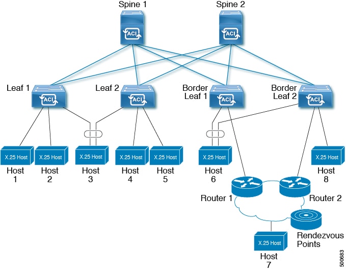
ACI ファブリックへのすべての外部接続がボーダー リーフ スイッチを介して維持されます。これは、ユニキャスト ピアリングとマルチキャスト ルーティングにも当てはまります。ほとんどの場合、ユニキャスト ルーティングとマルチキャスト ルーティングは、ユニキャスト ルーティング プロトコルを介して動作するマルチキャスト プロトコルにより、同じボーダー リーフ スイッチ上で一緒に動作します。
このアーキテクチャでは、ボーダー リーフ スイッチのみが完全な Protocol Independent Multicast(PIM)プロトコルを実行します。非ボーダー リーフ スイッチは、インターフェイス上でパッシブ モードの PIM を実行します。これらは、その他の PIM ルータとピアリングしません。ボーダー リーフ スイッチは、L3 Out を介してそれらの接続された他の PIM ルータとピアリングし、またそれら相互にもピアリングします。
次の図に、マルチキャスト クラウド内のルータ(R1 と R2)に接続しているボーダー リーフ(BL)スイッチを示します。マルチキャスト ルーティングを必要とするファブリック内の各 Virtual Routing and Forwarding(VRF)は、それぞれ別に外部マルチキャスト ルータとピアリングします。
レイヤ 3 マルチキャストの設定に関するガイドライン
次のガイドラインを参照してください。
-
レイヤ 3 マルチキャストの設定は VRF レベルで実行されます。そのため、VRF 内とマルチキャスト内のプロトコル機能が VRF で有効になり、各マルチキャスト VRF を個別にオンまたはオフにすることができます。
-
マルチキャストで VRF が有効になると、有効になった VRF の個別のブリッジ ドメイン(BD)と L3 Out を有効にしてマルチキャストを設定できます。デフォルトでは、マルチキャストはすべての BD およびレイヤ 3 Out で無効になっています。
-
現時点では、レイヤ 3 マルチキャストは、共有 L3 Out で設定された VRF ではサポートされていません。
-
Any Source Multicast(ASM)と Source-Specific Multicast(SSM)はサポートされています。
-
現時点では、双方向 PIM、ACI ファブリック内のランデブー ポイント(RP)、および PIM IPv6 はサポートされていません。
-
IGMP スヌーピングは、マルチキャスト ルーティングが有効になっているパーペイシブ ブリッジ ドメインでは無効にできません。
-
マルチキャスト ルータは、パーペイシブ ブリッジ ドメインではサポートされていません。
-
現在、レイヤ 3 マルチキャスト機能は、N9K-93180YC-EX モデル リーフ スイッチでサポートされています。
-
レイヤ 3 ポートとサブインターフェイスはサポートされていますが、外部 SVI はサポートされていません。外部 SVI がサポートされていないため、PIM を L3-VPC で有効にできません。
-
マルチキャスト ルーティングのために有効になっているブリッジ ドメインに接続された送信元からのパケットを入力リーフ スイッチが受信した場合、その入力リーフ スイッチは、ルーテッド VRF のコピーのみをファブリックに送信します(ルーテッドは、TTL が 1 ずつ減少し、送信元 MAC がパーベイシブ サブネット MAC で書き換えられることを意味します)。また、出力リーフ スイッチも、関連するすべてのブリッジ ドメイン内の受信者へパケットをルーティングします。そのため、受信者のブリッジ ドメインが送信元と同じで、リーフ スイッチが送信元とは異なる場合、その受信者は同じブリッジ ドメイン内であっても、ルーティングされたコピーを受け取り続けます。
レイヤ 3 マルチキャストの設定手順
ここでは、レイヤ 3 マルチキャストの設定手順を示します。手順は次のとおりです。
- レイヤ 3 マルチキャストの PIM オプションの設定
- レイヤ 3 マルチキャストの VRF での IGMP オプションの設定
- レイヤ 3 マルチキャストの L3 Out の設定
- 例:レイヤ 3 マルチキャストの設定
レイヤ 3 マルチキャストの PIM オプションの設定
| コマンドまたはアクション | 目的 | |
|---|---|---|
| ステップ 1 | configure 例: apic1# configure |
コンフィギュレーション モードに入ります。 |
| ステップ 2 | tenanttenant-name 例: apic1(config)# tenant exampleCorp |
設定するテナントを指定します。 |
| ステップ 3 | vrfcontextvrf-name 例: apic1(config-tenant)# vrf context exampleCorp_vrf1 |
テナントと VRF を関連付けます。 |
| ステップ 4 | [no]ippim 例: apic1(config-tenant-vrf)# ip pim |
Protocol Independent Multicast(PIM)を設定します。 |
| ステップ 5 | [no]ippimauto-rp {forward [listen] | listen | mapping-agent-policymapping-agent-policy-name} 例: apic1(config-tenant-vrf)# ip pim auto-rp forward listen |
(任意) PIM 自動 RP(ランデブー ポイント)オプションを設定します。Auto-RP は、PIM ネットワークにおけるグループから RP へのマッピングの配信を自動化します。自動 RP メッセージの転送、自動 RP メッセージのリッスン、またはマッピング エージェント メッセージのフィルタリングに対するルート マップ ポリシーの関連付けを選択できます。 |
| ステップ 6 | [no]ippimbsr {forward [listen] | listen | bsr-policymapping-agent-policy-name} 例: apic1(config-tenant-vrf)# ip pim bsr forward listen |
(任意) PIM ブートストラップ ルータ(BSR)オプションを設定します。BSR は、RP 機能およびグループの RP 情報のリレーに候補ルータを使用するという点において自動 RP と同様に動作します。RP 情報は、PIM メッセージ内で伝送される BSR メッセージを通じて配信されます。ブートストラップ/RP 候補メッセージの転送、ブートストラップ/RP 候補メッセージのリッスン、または BSR メッセージのフィルタリングに対するルート マップ ポリシーの関連付けを選択できます。 |
| ステップ 7 | [no]ippimfast-convergence 例: apic1(config-tenant-vrf)# ip pim fast-convergence |
(任意) PIM 高速コンバージェンス機能を有効にして、スイッチが応答しないネイバーを迅速に検出できるようにします。 |
| ステップ 8 | [no]ippimmtumtu-size 例: apic1(config-tenant-vrf)# ip pim mtu 1500 |
(任意) PIM メッセージの最大サイズを設定します。有効な範囲は 1500 ~ 65536 バイトです。 |
| ステップ 9 | [no]ippimregister-policyregister-policy-name 例: apic1(config-tenant-vrf)# ip pim register-policy regPolicy1 |
(任意) 登録メッセージのフィルタリングにポリシーの名前を指定します。 |
| ステップ 10 | [no]ippimregister-rate-limitmtu-size 例: apic1(config-tenant-vrf)# ip pim register-rate-limit 1024 |
(任意) PIM データ レジスタにレート制限を指定します。範囲は毎秒 0 ~ 65535 パケットです。 |
| ステップ 11 | [no]ippimregister-sourceip-address 例: apic1(config-tenant-vrf)# ip pim register-source 192.0.20.123 |
(任意) PIM メッセージの送信元 IP アドレスを設定します。 |
| ステップ 12 | [no]ippimrp-addressip-address [route-maproute-map-name] 例: apic1(config-tenant-vrf)# ip pim rp-address 192.0.20.99 |
(任意) マルチキャスト グループ範囲に、静的ルート プロセッサ(RP)アドレスを設定します。 |
| ステップ 13 | [no]ippimsg-expiry-timerip-address [sg-listroute-map-name] 例: apic1(config-tenant-vrf)# ip pim sg-expiry-timer 4096 |
(任意) PIM スパース モード(PIM-SM)(S, G) マルチキャスト ルートに(S, G)期限切れタイマーの間隔を設定します。値の範囲は 180 ~ 604801 秒です。オプションの sg-list パラメータで、タイマーが適用する S,G 値を指定します。デフォルトは 4096 です。 |
| ステップ 14 | [no]ippimssmroute-maproute-map-name 例: apic1(config-tenant-vrf)# ip pim ssm route-map SSMRtMap |
(任意) IP マルチキャストの拡張機能である Source Specific Multicas(SSM)を設定します。この機能を使用すると、受信者に転送されるデータグラム トラフィックは、その受信者が明示的に加入しているマルチキャスト送信元からのトラフィックだけになります。ルート マップ ポリシーは、グループのプレフィクスのリストを表示します。 |
| ステップ 15 | [no]ippimstate-limitmax-entries [reservedroute-map-name [maximum-reserve-state-entries]] 例: apic1(config-tenant-vrf)# ip pim state-limit 100000 reserved myReservedPolicy 40000 |
(任意) 現在の VRF インスタンスの PIM の状態エントリの最大数を設定します。最大状態エントリ数の範囲は 0 ~ 4294967295 です。オプションで、ポリシー マップに指定されるルート用に予約する状態エントリの数を指定することができ、また、この VRF で許可される最大予約済み(*, G)と(S, G)エントリを指定できます。子の数は、許可される最大状態数以下である必要があります。範囲は 1 ~ 4294967295 です。 |
| ステップ 16 | [no]ippimuse-shared-tree-onlygroup-listpolicy-name 例: apic1(config-tenant-vrf)# ip pim use-shared-tree-only group-list myGroup1 |
(任意) PIM(*, G)状態のみを作成します(送信元の状態を作成しない場合)。このポリシーで、この機能を適用するグループ プレフィックスを定義します。 |
| ステップ 17 | exit 例: apic1(config-tenant-vrf)# exit |
テナント コンフィギュレーション モードに戻ります。 |
VRF の IGMP オプションを設定します。
レイヤ 3 マルチキャストの VRF での IGMP オプションの設定
テナント VRF の PIM オプションを設定します。
| コマンドまたはアクション | 目的 | |
|---|---|---|
| ステップ 1 | configure 例: apic1# configure |
コンフィギュレーション モードを開始します。 |
| ステップ 2 | tenanttenant-name 例: apic1(config)# tenant exampleCorp |
設定するテナントを指定します。 |
| ステップ 3 | vrfcontextvrf-name 例: apic1(config-tenant)# vrf context vrf1 |
テナントと VRF を関連付けます。 |
| ステップ 4 | [no]ipigmp 例: apic1(config-tenant-vrf)# ip igmp |
インターネット グループ管理プロトコル(IGMP)を有効にします。 |
| ステップ 5 | exit 例: apic1(config-tenant-vrf)# exit |
テナント コンフィギュレーション モードに戻ります。 |
| ステップ 6 | interfacebridge-domainbd-name 例: apic1(config-tenant)# interface bridge-domain exampleCorp_bd1 |
テナント インターフェイス コンフィギュレーション モードを開始してブリッジ ドメインを設定します。 |
| ステップ 7 | [no]ipmulticast 例: apic1(config-tenant-interface)# ip multicast |
インターフェイスで IP マルチキャスト ルーティングを有効にします。 |
| ステップ 8 | [no]ipigmpallow-v3-asm 例: apic1(config-tenant-interface)# ip igmp allow-v3-asm |
Any Source Multicast(ASM)グループに関する IGMPv3 レポートの送信元アドレスのフィルタリングを許可します。 |
| ステップ 9 | [no]ipigmpfast-leave 例: apic1(config-tenant-interface)# ip igmp fast-leave |
IP IGMP スヌーピングの高速脱退処理を有効にします。この機能は、IGMPv2 プロトコルのホスト レポート抑制メカニズムのために明示的に追跡できない IGMPv2 ホストをサポートします。高速脱退が有効になっている場合、IGMP ソフトウェアは、各ポートに接続されたホストが 1 つだけであると見なします。 |
| ステップ 10 | [no]ipigmpgroup-timeoutseconds 例: apic1(config-tenant-interface)# ip igmp group-timeout 260 |
IGMPv2 のグループ メンバーシップ タイムアウトを設定します。値の範囲は 3 ~ 65535 秒です。デフォルト値は 260 秒です。 |
| ステップ 11 | [no]ipigmpinheritinterface-policypolicy-name 例: apic1(config-tenant-interface)# ip igmp inherit interface-policy MyIfPolicy |
このインターフェイスに IGMP インターフェイス ポリシーを関連付けます。 |
| ステップ 12 | [no]ipigmpjoin-grouproute-maproute-map-name 例: apic1(config-tenant-interface)# ip igmp join-group route-map MyGroupsRMap |
1 つ以上のマルチキャスト グループをインターフェイスに静的にバインドします。ルート マップ ポリシーは、グループのプレフィクス、グループの範囲、および送信元プレフィクスのリストを表示します。 |
| ステップ 13 | [no]ipigmplast-member-query-countcount 例: apic1(config-tenant-interface)# ip igmp last-member-query-count 2 |
ホストの Leave メッセージを受信してから、IGMP クエリーが送信される回数を設定します。範囲は 1 ~ 5 クエリーです。デフォルトは 2 クエリーです。 |
| ステップ 14 | [no]ipigmplast-member-query-response-timeseconds 例: apic1(config-tenant-interface)# ip igmp last-member-query-response-time 1 |
メンバーシップ レポートを送信してから、ソフトウェアがグループ ステートを解除するまでのクエリー インターバルを設定します。値の範囲は 1 ~ 25 秒です。デフォルト値は 1 秒です。 |
| ステップ 15 | [no]ipigmpquerier-timeoutseconds 例: apic1(config-tenant-interface)# ip igmp querier-timeout 255 |
前クエリアがクエリーを停止してから、自身がクエリアとして処理を引き継ぐまで、ソフトウェアが待機する秒数を設定します。指定できる範囲は 1 ~ 65535 秒です。デフォルト値は 255 秒です。 |
| ステップ 16 | [no]ipigmpquery-intervalseconds 例: apic1(config-tenant-interface)# ip igmp query-interval 125 |
IGMP ホスト クエリー メッセージの送信頻度を設定します。大きな値を設定すると、ソフトウェアによる IGMP クエリーの送信頻度が低くなるため、ネットワーク上の IGMP メッセージ数を調整できます。指定できる範囲は 1 ~ 18000 秒です。デフォルト値は 125 秒です。 |
| ステップ 17 | [no]ipigmpquery-max-response-timeseconds 例: apic1(config-tenant-interface)# ip igmp query-max-response-time 10 |
IGMP クエリーでアドバタイズされる応答時間を設定します。大きな値を設定すると、ホストの応答時間が延長されるため、ネットワークの IGMP メッセージのバースト性を調整できます。この値は、クエリー インターバルよりも短く設定する必要があります。値の範囲は 1 ~ 25 秒です。デフォルトは 10 秒です。 |
| ステップ 18 | [no]ipigmpreport-link-local-groups 例: apic1(config-tenant-interface)# ip igmp report-link-local-groups |
224.0.0.0/24 に含まれるグループに対して、レポート送信をイネーブルにします。リンク ローカル アドレスは、ローカル ネットワーク プロトコルだけで使用されます。非リンク ローカル グループには、常にレポートが送信されます。デフォルトでは、リンク ローカル グループにレポートは送信されません。 |
| ステップ 19 | [no]ipigmpreport-policypolicy-name 例: apic1(config-tenant-interface)# ip igmp report-policy MyReportPolicy |
ルートマップ ポリシーに基づく、IGMP レポートのアクセス ポリシーを設定します。 |
| ステップ 20 | [no]ipigmprobustness-variablevalue 例: apic1(config-tenant-interface)# ip igmp robustness-variable 2 |
輻輳ネットワーク上のパケット損失を補うようにロバストネス変数を設定します。ロバストネス値は、IGMP ソフトウェアがメッセージ送信回数を確認するために使用されます。ネットワークのパケット損失が多い場合は、この値を大きくします。指定できる範囲は 1 ~ 7 です。デフォルトは 2 です。 |
| ステップ 21 | [no]ipigmpsnooping 例: apic1(config-tenant-interface)# ip igmp snooping |
インターフェイスに対して IGMP スヌーピングを有効にします。 |
| ステップ 22 | [no]ipigmpsnoopingfast-leave 例: apic1(config-tenant-interface)# ip igmp snooping fast-leave |
ソフトウェアが IGMP Leave レポートを受信した場合に、IGMP クエリー メッセージを送信することなく、グループ ステートを解除できるようにします。このパラメータは、IGMPv2 ホストに関して、各ポート上のホストが 1 つしか存在しない場合に使用されます。 |
| ステップ 23 | [no]ipigmpsnoopinglast-member-query-interval 例: apic1(config-tenant-interface)# ip igmp snooping last-member-query-interval 5 |
時間間隔を秒単位で設定します。この時間が経過しても IGMP クエリー メッセージにホストが 1 つも応答しない場合は、関連するポートからこのグループが削除されます。値の範囲は 1 ~ 25 秒です。デフォルトは 5 秒です。 |
| ステップ 24 | [no]ipigmpsnoopingoptimise-multicast-flood 例: apic1(config-tenant-interface)# ip igmp snooping optimise-multicast-flood |
不明なトラフィックをルータのみに転送し、データによる状態の作成を実行しない Optimized Multicast Flood(OMF)を設定します。 |
| ステップ 25 | [no]ipigmpsnoopingpolicypolicy-name 例: apic1(config-tenant-interface)# ip igmp snooping policy MySnoopingPolicy |
IGMP スヌーピング ポリシーとブリッジ ドメインを関連付けます。 |
| ステップ 26 | [no]ipigmpsnoopingquerier 例: apic1(config-tenant-interface)# ip igmp snooping querier |
IP IGMP スヌーピング クエリアを有効にして、IP マルチキャスト トラフィックを受信するホストから IGMP レポート メッセージをトリガーする IGMP クエリーを定期的に送信します。IGMP スヌーピングはこれらの IGMP レポートを待ち受けて、適切な転送を確立します。 |
| ステップ 27 | [no]ipigmpsnoopingquery-intervalseconds 例: apic1(config-tenant-interface)# ip igmp snooping query-interval 125 |
マルチキャスト トラフィックをルーティングする必要がないため、PIM をイネーブルにしていない場合に、スヌーピング クエリー インターバルを設定します。指定できる範囲は 1 ~ 18000 秒です。デフォルト値は 125 秒です。 |
| ステップ 28 | [no]ipigmpsnoopingquery-max-response-timeseconds 例: apic1(config-tenant-interface)# ip igmp snooping query-max-response-time 10 |
マルチキャスト トラフィックをルーティングする必要がないため PIM を無効にしている場合に対して、クエリー メッセージのスヌーピング最大応答時間を設定します。値の範囲は 1 ~ 25 秒です。デフォルトは 10 秒です。 |
| ステップ 29 | [no]ipigmpsnoopingstartup-query-countcount 例: apic1(config-tenant-interface)# ip igmp snooping startup-query-count 5 |
マルチキャスト トラフィックをルーティングする必要がないため、PIM をイネーブルにしていない場合に、起動時に送信されるクエリー数に対してスヌーピングを設定します。範囲は 1 ~ 10 クエリーです。デフォルトは 5 クエリーです。 |
| ステップ 30 | [no]ipigmpsnoopingstartup-query-intervalseconds 例: apic1(config-tenant-interface)# ip igmp snooping startup-query-interval 15000 |
マルチキャスト トラフィックをルーティングする必要がないため、PIM をイネーブルにしていない場合に、起動時のスヌーピング クエリー インターバルを設定します。指定できる範囲は 1 ~ 18000 秒です。デフォルト値は 15000 秒です。 |
| ステップ 31 | [no]ipigmpstartup-query-countcount 例: apic1(config-tenant-interface)# ip igmp startup-query-count 2 |
スタートアップ クエリー インターバル中に送信される起動時のクエリー数を設定します。範囲は 1 ~ 10 クエリーです。デフォルトは 2 クエリーです。 |
| ステップ 32 | [no]ipigmpstartup-query-intervalseconds 例: apic1(config-tenant-interface)# ip igmp startup-query-interval 31 |
ソフトウェアの起動時に使用されるクエリー インターバルを設定します。デフォルトでは、ソフトウェアができるだけ迅速にグループ ステートを確立できるように、このインターバルはクエリー インターバルより短く設定されています。指定できる範囲は 1 ~ 18000 秒です。デフォルト値は 260 秒です。デフォルト値は 31 秒です。 |
| ステップ 33 | [no]ipigmpstate-limitmax-states [reservedroute-map-name [max-reserved-gsg-entries]] 例: apic1(config-tenant-interface)# ip igmp state-limit 100000 reserved myReservedPolicy 40000 |
IGMP メンバーシップ レポート(IGMP 加入)の結果として作成される mroute ステートの数に対するインターフェイスごとの制限を設定します。許可される状態の範囲は 1 ~ 4294967295 です。オプションで、ポリシー マップに指定されるルート用に予約する状態エントリの数を指定することができ、また、インターフェイスで許可される最大予約済み (*, G) と (S, G) エントリを指定できます。予約済み状態の数は、許可される最大状態数以下である必要があります。範囲は 1 ~ 4294967295 です。 |
| ステップ 34 | [no]ipigmpstatic-oifroute-maproute-map-name 例: apic1(config-tenant-interface)# ip igmp static-oif route-map MyOifMap |
マルチキャスト グループを発信インターフェイス(OIF)に静的にバインドし、デバイス ハードウェアで処理します。ルート マップは、この機能を適用するグループ プレフィックスを定義します。 |
| ステップ 35 | [no]ipigmpversion {v1 | v2 | v3} 例: apic1(config-tenant-interface)# ip igmp version v3 |
インターフェイスの IGMP バージョン番号を設定します。デフォルトのバージョンは v2 です。 |
| ステップ 36 | exit 例: apic1(config-tenant-interface)# exit |
テナント コンフィギュレーション モードに戻ります。 |
テナントに L3 Out を設定し、PIM を有効にしてリーフ インターフェイスを設定します。
レイヤ 3 マルチキャストの L3 Out の設定
| コマンドまたはアクション | 目的 | |
|---|---|---|
| ステップ 1 | configure 例: apic1# configure |
コンフィギュレーション モードに入ります。 |
| ステップ 2 | tenanttenant-name 例: apic1(config)# tenant exampleCorp |
設定するテナントを指定します。 |
| ステップ 3 | l3outl3out-name 例: apic1(config-tenant)# l3out exampleCorp_l3out |
テナントに L3 Out のインターフェイスを設定します。 |
| ステップ 4 | ippim 例: apic1(config-tenant-l3out)# ip pim |
インターフェイスで PIM をイネーブルにします。 |
| ステップ 5 | exit 例: apic1(config-tenant-l3out)# |
テナント コンフィギュレーション モードに戻ります。 |
| ステップ 6 | exit 例: apic1(config-tenant)# exit |
グローバル コンフィギュレーション モードに戻ります。 |
| ステップ 7 | leafnode-id 例: apic1(config)# leaf 101 |
リーフ コンフィギュレーション モードを開始します。 |
| ステップ 8 | interfaceethernetslot/port 例: apic1(config-leaf)# interface ethernet 1/3 |
設定するインターフェイスを指定します。 |
| ステップ 9 | [no]ipigmpallow-v3-asm 例: apic1(config-leaf-if)# ip igmp allow-v3-asm |
Any Source Multicast(ASM)グループに関する IGMPv3 レポートの送信元アドレスのフィルタリングを許可します。 |
| ステップ 10 | [no]ipigmpfast-leave 例: apic1(config-leaf-if)# ip igmp fast-leave |
IP IGMP スヌーピングの高速脱退処理を有効にします。この機能は、IGMPv2 プロトコルのホスト レポート抑制メカニズムのために明示的に追跡できない IGMPv2 ホストをサポートします。高速脱退が有効になっている場合、IGMP ソフトウェアは、各ポートに接続されたホストが 1 つだけであると見なします。 |
| ステップ 11 | [no]ipigmpgroup-timeoutseconds 例: apic1(config-leaf-if)# ip igmp group-timeout 260 |
IGMPv2 のグループ メンバーシップ タイムアウトを設定します。値の範囲は 3 ~ 65535 秒です。デフォルト値は 260 秒です。 |
| ステップ 12 | [no]ipigmpinheritinterface-policypolicy-name 例: apic1(config-leaf-if)# ip igmp inherit interface-policy MyIfPolicy |
このインターフェイスに IGMP インターフェイス ポリシーを関連付けます。 |
| ステップ 13 | [no]ipigmpjoin-grouproute-maproute-map-name 例: apic1(config-leaf-if)# ip igmp join-group route-map MyGroupsRMap |
1 つ以上のマルチキャスト グループをインターフェイスに静的にバインドします。ルート マップ ポリシーは、グループのプレフィクス、グループの範囲、および送信元プレフィクスのリストを表示します。 |
| ステップ 14 | [no]ipigmplast-member-query-countcount 例: apic1(config-leaf-if)# ip igmp last-member-query-count 2 |
ホストの Leave メッセージを受信してから、IGMP クエリーが送信される回数を設定します。範囲は 1 ~ 5 クエリーです。デフォルトは 2 クエリーです。 |
| ステップ 15 | [no]ipigmplast-member-query-response-timeseconds 例: apic1(config-leaf-if)# ip igmp last-member-query-response-time 1 |
メンバーシップ レポートを送信してから、ソフトウェアがグループ ステートを解除するまでのクエリー インターバルを設定します。値の範囲は 1 ~ 25 秒です。デフォルト値は 1 秒です。 |
| ステップ 16 | [no]ipigmpquerier-timeoutseconds 例: apic1(config-leaf-if)# ip igmp querier-timeout 255 |
前のクエリアがクエリーを停止してから、自身がクエリアとして処理を引き継ぐまで、ソフトウェアが待機する秒数を設定します。指定できる範囲は 1 ~ 65535 秒です。デフォルト値は 255 秒です。 |
| ステップ 17 | [no]ipigmpquery-intervalseconds 例: apic1(config-leaf-if)# ip igmp query-interval 125 |
IGMP ホスト クエリー メッセージの送信頻度を設定します。大きな値を設定すると、ソフトウェアによる IGMP クエリーの送信頻度が低くなるため、ネットワーク上の IGMP メッセージ数を調整できます。指定できる範囲は 1 ~ 18000 秒です。デフォルト値は 125 秒です。 |
| ステップ 18 | [no]ipigmpquery-max-response-timeseconds 例: apic1(config-leaf-if)# ip igmp query-max-response-time 10 |
IGMP クエリーでアドバタイズされる応答時間を設定します。大きな値を設定すると、ホストの応答時間が延長されるため、ネットワークの IGMP メッセージのバースト性を調整できます。この値は、クエリー インターバルよりも短く設定する必要があります。値の範囲は 1 ~ 25 秒です。デフォルトは 10 秒です。 |
| ステップ 19 | [no]ipigmpreport-link-local-groups 例: apic1(config-leaf-if)# ip igmp report-link-local-groups |
224.0.0.0/24 に含まれるグループに対して、レポート送信をイネーブルにします。リンク ローカル アドレスは、ローカル ネットワーク プロトコルだけで使用されます。非リンク ローカル グループには、常にレポートが送信されます。デフォルトでは、リンク ローカル グループにレポートは送信されません。 |
| ステップ 20 | [no]ipigmpreport-policypolicy-name 例: apic1(config-leaf-if)# ip igmp report-policy MyReportPolicy |
ルートマップ ポリシーに基づく、IGMP レポートのアクセス ポリシーを設定します。 |
| ステップ 21 | [no]ipigmprobustness-variablevalue 例: apic1(config-leaf-if)# ip igmp robustness-variable 2 |
輻輳ネットワーク上のパケット損失を補うようにロバストネス変数を設定します。ロバストネス値は、IGMP ソフトウェアがメッセージ送信回数を確認するために使用されます。ネットワークのパケット損失が多い場合は、この値を大きくします。指定できる範囲は 1 ~ 7 です。デフォルトは 2 です。 |
| ステップ 22 | [no]ipigmpstartup-query-countcount 例: apic1(config-leaf-if)# ip igmp startup-query-count 2 |
スタートアップ クエリー インターバル中に送信される起動時のクエリー数を設定します。範囲は 1 ~ 10 クエリーです。デフォルトは 2 クエリーです。 |
| ステップ 23 | [no]ipigmpstartup-query-intervalseconds 例: apic1(config-leaf-if)# ip igmp startup-query-interval 31 |
ソフトウェアの起動時に使用されるクエリー インターバルを設定します。デフォルトでは、ソフトウェアができるだけ迅速にグループ ステートを確立できるように、このインターバルはクエリー インターバルより短く設定されています。指定できる範囲は 1 ~ 18000 秒です。デフォルト値は 260 秒です。デフォルト値は 31 秒です。 |
| ステップ 24 | [no]ipigmpstate-limitmax-states [reservedroute-map-name [max-reserved-gsg-entries]] 例: apic1(config-leaf-if)# ip igmp state-limit 100000 reserved myReservedPolicy 40000 |
IGMP メンバーシップ レポート(IGMP 加入)の結果として作成される mroute ステートの数に対するインターフェイスごとの制限を設定します。許可される状態の範囲は 1 ~ 4294967295 です。オプションで、ポリシー マップに指定されるルート用に予約する状態エントリの数を指定することができ、また、インターフェイスで許可される最大予約済み (*, G) と (S, G) エントリを指定できます。予約済み状態の数は、許可される最大状態数以下である必要があります。範囲は 1 ~ 4294967295 です。 |
| ステップ 25 | [no]ipigmpstatic-oifroute-maproute-map-name 例: apic1(config-leaf-if)# ip igmp static-oif route-map MyOifMap |
マルチキャスト グループを発信インターフェイス(OIF)に静的にバインドし、デバイス ハードウェアで処理します。ルート マップは、この機能を適用するグループ プレフィックスを定義します。 |
| ステップ 26 | [no]ipigmpversion {v1 | v2 | v3} 例: apic1(config-leaf-if)# ip igmp version v3 |
インターフェイスの IGMP バージョン番号を設定します。デフォルトのバージョンは v2 です。 |
| ステップ 27 | exit 例: apic1(config-leaf-if)# exit |
テナント コンフィギュレーション モードに戻ります。 |
例:レイヤ 3 マルチキャストの設定
# CONFIGURE PIM OPTIONS ON A TENANT VRF

apic1# configure
apic1(config)# tenant exampleCorp
apic1(config-tenant)# vrf context exampleCorp_vrf1
apic1(config-tenant-vrf)# ip pim
apic1(config-tenant-vrf)# ip pim fast-convergence
apic1(config-tenant-vrf)# ip pim bsr forward

# ENABLE AND CONFIGURE IGMP ON THE TENANT VRF AND BRIDGE DOMAIN

apic1(config-tenant-vrf)# ip igmp
apic1(config-tenant-vrf)# exit
apic1(config-tenant)# interface bridge-domain exampleCorp_bd
apic1(config-tenant-interface)# ip multicast
apic1(config-tenant-interface)# ip igmp allow-v3-asm
apic1(config-tenant-interface)# ip igmp fast-leave
apic1(config-tenant-interface)# exit

# CREATE AN L3OUT AND CONFIGURE PIM

apic1(config-tenant)# l3out exampleCorp_l3out
apic1(config-tenant-l3out)# ip pim
apic1(config-tenant-l3out)# exit
apic1(config-tenant)# exit

# CONFIGURE AN EXTERNAL INTERFACE AND CONFIGURE IGMP ON THE INTERFACE

apic1(config)# leaf 101
apic1(config-leaf)# interface ethernet 1/125
apic1(config-leaf-if)# ip igmp fast-leave
apic1(config-leaf-if)# ip-igmp join-group
外部 L3 EPG の設定
外部 L3 EPG はテナント VRF 下に分類されます。CLI で、外部 L3 EPG はテナント モードで定義され、個々のノードに展開されます。VRF のすべてのノードではなく一部のノードに外部 L3 EPG を配置することができます。
外部 L3 EPG はそれぞれ複数のコントラクトのプロデューサまたはコンシューマになることができ、外部 L3 EPG にはそれぞれファブリック内の DSCP マーキングおよびキューイング プライオリティに関する独自の QoS ポリシーがあります。
| コマンドまたはアクション | 目的 | |
|---|---|---|
| ステップ 1 | configure 例: apic1# configure |
コンフィギュレーション モードに入ります。 |
| ステップ 2 | tenanttenant-name 例: apic1(config)# tenant exampleCorp |
テナント コンフィギュレーション モードを開始します。 |
| ステップ 3 | external-l3epgepg-name 例: apic1(config-tenant)# external-l3 epg epgExtern1 |
外部 L3 EPG コンフィギュレーション モードを開始します。 |
| ステップ 4 | vrfmembervrf-name 例: apic1(config-tenant-l3ext-epg)# vrf member v1 |
EPG を VRF に関連付けます。 |
| ステップ 5 | match {ip | ipv6} ip-address/masklength 例: apic1(config-tenant-l3ext-epg)# match ip 192.0.20.0/24 apic1(config-tenant-l3ext-epg)# match ipv6 2001::1/64 |
サブネットに一致するルールを作成します。 |
| ステップ 6 | setqos-classclass 例: apic1(config-tenant-l3ext-epg)# set qos-class level1 |
EPG の QoS レベルを指定します。 |
| ステップ 7 | setdscpdscp-value 例: apic1(config-tenant-l3ext-epg)# set dscp af31 |
EPG の DSCP 値を指定します。 |
| ステップ 8 | contractconsumercontract-name 例: apic1(config-tenant-l3ext-epg)# contract consumer cConsumer1 |
EPG のコンシューマ コントラクトを指定します。 |
| ステップ 9 | contractprovidercontract-name 例: apic1(config-tenant-l3ext-epg)# contract provider cProvider1 |
EPG のプロバイダー コントラクトを指定します。 |
| ステップ 10 | contractdenycontract-name 例: apic1(config-tenant-l3ext-epg)# contract deny cDeny1 |
EPG の拒否コントラクトを指定します。 |
| ステップ 11 | exit 例: apic1(config-tenant-l3ext-epg)# exit |
|
| ステップ 12 | exit 例: apic1(config-tenant)# exit |
|
| ステップ 13 | leafnode-id 例: apic1(config)# leaf 101 |
設定するリーフを指定します。 |
| ステップ 14 | vrfcontexttenanttenant-namevrfvrf-name 例: apic1(config-leaf)# vrf context tenant exampleCorp vrf v1 |
ノードのテナント VRF を設定します。 |
| ステップ 15 | external-l3epgepg-name 例: apic1(config-leaf-vrf)# external-l3 epg epgExtern1 |
VRF の外部レイヤ 3 EPG を関連付けます。 |
例
次に、外部レイヤ 3 EPG を設定し、リーフに EPG を展開する例を示します。
apic1# configure
apic1(config)# tenant exampleCorp
# CONFIGURE EXTERNAL L3 EPG
apic1(config-tenant)# external-l3 epg epgExtern1
apic1(config-tenant-l3ext-epg)# vrf member v1
apic1(config-tenant-l3ext-epg)# match ip 192.0.20.0/24
apic1(config-tenant-l3ext-epg)# match ipv6 2001::1/64
apic1(config-tenant-l3ext-epg)# set qos-class level1
apic1(config-tenant-l3ext-epg)# set dscp af31
apic1(config-tenant-l3ext-epg)# contract consumer cConsumer1
apic1(config-tenant-l3ext-epg)# contract provider cProvider1
apic1(config-tenant-l3ext-epg)# contract deny cDeny1
apic1(config-tenant-l3ext-epg)# exit
apic1(config-tenant)# exit
# DEPLOY EXTERNAL L3 EPG ON A LEAF
apic1(config)# leaf 101
apic1(config-leaf)# vrf context tenant exampleCorp vrf v1
apic1(config-leaf-vrf)# external-l3 epg epgExtern1
名前付き L3Out の作成
| コマンドまたはアクション | 目的 | |
|---|---|---|
| ステップ 1 | configure 例: apic1# configure |
コンフィギュレーション モードに入ります。 |
| ステップ 2 | tenanttenant-name 例: apic1(config)# tenant exampleCorp |
テナント コンフィギュレーション モードを開始します。 |
| ステップ 3 | vrfcontextvrf-name 例: apic1(config-tenant)# vrf context v1 |
テナントを VRF に関連付けます。 |
| ステップ 4 | l3outl3out-name 例: apic1(config-tenant)# l3out out1 |
名前付き L3Out を作成します。 |
| ステップ 5 | vrfmembervrf-name 例: apic1(config-tenant-l3out)# vrf member v1 |
L3Out をテナント VRF と関連付けます。 |
| ステップ 6 | exit 例: apic1(config-tenant-l3out)# exit |
テナント コンフィギュレーション モードに戻ります。 |
| ステップ 7 | exit 例: apic1(config-tenant)# exit |
グローバル コンフィギュレーション モードに戻ります。 |
| ステップ 8 | leafnode-id 例: apic1(config)# leaf 101 |
ノード |
| ステップ 9 | vrfcontexttenanttenant-namevrfvrf-namel3outl3out-name 例: apic1(config-leaf)# vrf context tenant exampleCorp vrf v1 l3out out1 |
ノードのテナント VRF を設定します。 |
| ステップ 10 | [no]router-idipv4-address 例: apic1(config-leaf-vrf)# router-id 1.2.3.4 |
VRF で実行されているルーティング プロトコルに対してルータ ID を割り当てます。 |
| ステップ 11 | [no] {ip | ipv6} routeip-prefix/masklennext-hop-address[preferred] 例: apic1(config-leaf-vrf)# ip route 21.1.1.1/32 32.1.1.1 apic1(config-leaf-vrf)# ipv6 route 5001::1/128 6002::1 |
VRF の静的ルートの情報を設定します。 |
例
次に、テナントの下に名前付き L3Out を作成し、テナント VRF に割り当て、境界リーフ スイッチに導入する例を示します。
apic1# configure
apic1(config)# tenant exampleCorp
apic1(config-tenant)# vrf context v1
apic1(config-tenant)# l3out out1
apic1(config-tenant-l3out)# vrf member v1
apic1(config-tenant-l3out)# exit
apic1(config-tenant)# exit
apic1(config)# leaf 101
apic1(config-leaf)# vrf context tenant exampleCorp vrf v1 l3out out1
apic1(config-leaf-vrf)# router-id 1.2.3.4
apic1(config-leaf-vrf)# ip route 21.1.1.1/32 32.1.1.1
名前付き L3Out のレイヤ 3 インターフェイスを設定します。
名前付き L3Out のレイヤ 3 インターフェイスの設定
この手順では、名前付き L3Out にレイヤ 3 ポート インターフェイスを設定する方法を示します。例では、名前付き L3Out にサブインターフェイスまたは SVI を設定する方法を示します。
名前付き L3Out を作成します。
| コマンドまたはアクション | 目的 | |
|---|---|---|
| ステップ 1 | configure 例: apic1# configure |
コンフィギュレーション モードに入ります。 |
| ステップ 2 | leafnode-id 例: apic1(config)# leaf 101 |
設定するリーフを指定します。 |
| ステップ 3 | interfacetype 例: apic1(config-leaf)# interface eth 1/20 |
外部インターフェイスのポートを指定します。 |
| ステップ 4 | noswitchport 例: apic1(config-leaf-if)# no switchport |
インターフェイスをレイヤ 3 インターフェイスとして設定し、設定オプションでレイヤ 3 コマンドを公開します。 |
| ステップ 5 | vrfmembertenanttenant-namevrfvrf-namel3outl3out-name 例: apic1(config-leaf-if)# vrf member tenant exampleCorp vrf v1 l3out out1 |
テナント VRF にインターフェイスを接続します。 |
| ステップ 6 | [no] {ip | ipv6} addressip-prefix/masklen[eui64][secondary][preferred] 例: apic1(config-leaf-if)# ip address 10.1.1.1/24 apic1(config-leaf-if)# ipv6 address 2001::1/64 preferred |
インターフェイスに IP アドレスを設定します。指定されたアドレスは次のいずれかとして宣言できます。 オプションの eui64 キーワードを使用すると、ホストは自身に Extended Unique Identifier(EUI; 拡張固有識別子)を割り当てることができます。 このモードでは、インターフェイスに ipv6 link-local、mac address、mtu、およびその他のレイヤ 3 プロパティを設定することもできます。 |
例
次に、名前付き L3Out にレイヤ 3 ポートを割り当てる例を示します。
apic1# configure
apic1(config)# leaf 101
apic1(config-leaf)# interface eth 1/20
apic1(config-leaf-if)# no switchport
apic1(config-leaf-if)# vrf member tenant exampleCorp vrf v1 l3out out1
apic1(config-leaf-if)# ip address 10.1.1.1/24
apic1(config-leaf-if)# ipv6 address 2001::1/64 preferred
次に、名前付き L3Out にレイヤ 3 サブインターフェイスを割り当てる例を示します。
apic1# configure
apic1(config)# leaf 101
apic1(config-leaf)# interface eth 1/5
apic1(config-leaf-if)# no switchport
apic1(config-leaf-if)# vlan-domain member d1
apic1(config-leaf-if)# exit
apic1(config-leaf)# interface ethernet 1/5.1000
apic1(config-leaf-if)# vrf member tenant exampleCorp vrf v1 l3out out1
apic1(config-leaf-if)# ip address 10.1.1.1/24
apic1(config-leaf-if)# ipv6 address 2001::1/64 preferred
次に、名前付き L3Out にレイヤ 3 SVI を割り当てる例を示します。
apic1# configure
apic1(config)# leaf 101
apic1(config-leaf)# interface vlan 200
apic1(config-leaf-if)# vrf member tenant exampleCorp vrf v1
apic1(config-leaf-if)# ip address 10.1.1.1/24
apic1(config-leaf-if)# exit
apic1(config-leaf)# interface ethernet 1/4
apic1(config-leaf-if)# vlan-domain member d1
apic1(config-leaf-if)# switchport trunk allowed vlan 200 tenant t1 external-svi l3out out1
名前付き L3Out のルート マップの設定
-
ルートマップはリーフ、VRF モードで設定します。
-
次のルートマップは、すべての名前付き L3Out に対して作成されます。
-
エクスポート:L3Out で有効なルーティング プロトコルからアドバタイズされるルートのルートマップ。デフォルトでは、match bridge-domain、match prefix-list、および match community-list の 1 つ以上のステートメントによってルートを明示的に有効にするまで、ルートはエクスポートされません。
-
インポート:L3Out のルーティング プロトコルにインポートされるルートのルートマップ。デフォルトでは、すべてのルートがインポートされます。1 つ以上の match prefix-list または match community-list ステートメントを使用してインポートする特定のルートを制御できます。
-
共有:ルートと、この VRF からコントラクトの関連付けがあるその他の VRF へのルートをリークするために使用されるコントラクト プロバイダー/コンシューマ ポリシーを含むルートマップ。
これらのルートマップは、vrf context tenanttenant-namevrfvrf-namel3outl3out-name コマンドを使用して L3Out にリーフを関連付けるときに作成されます。
-
- 名前付き L3Out 下のルートマップのスコープは常にグローバルであり、名前付き L3Out が展開されているすべてのノードに適用できます。
-
ルートマップ下のすべてのコマンド(match prefix-list、match community-list、match bridge-domain など)は、前の項で説明した基本モードのルートマップ設定と同じです。
名前付き L3Out を作成します。
| コマンドまたはアクション | 目的 | |
|---|---|---|
| ステップ 1 | configure 例: apic1# configure |
コンフィギュレーション モードに入ります。 |
| ステップ 2 | leafnode-id 例: apic1(config)# leaf 101 |
設定するリーフを指定します。 |
| ステップ 3 | [no]vrfcontexttenanttenant-namevrfvrf-namel3outl3out-name 例: apic1(config-leaf)# vrf context tenant exampleCorp vrf v1 l3out out1 |
ノードのテナント VRF を設定します。 |
| ステップ 4 | [no]route-mapname 例: apic1(config-leaf-vrf)# route-map out1_in |
ルートマップを作成し、ルートマップ コンフィギュレーションを開始します。これがインポート ルートマップになります。 |
| ステップ 5 | [no]ipprefix-listlist-namepermitprefix/masklen [le {32 | 128}] 例: apic1(config-leaf-vrf-route-map)# ip prefix-list p1 permit 15.1.1.0/24 |
ルートマップにプレフィックスリストを作成します。 |
| ステップ 6 | [no]matchprefix-listlist-name 例: apic1(config-leaf-vrf-route-map)# match prefix-list p1 |
作成済みのプレフィックスリストと照合し、一致モードを開始して、プレフィックスリストのルート制御プロファイルを設定します。 |
| ステップ 7 | exit 例: apic1(config-leaf-vrf-route-map-match)# exit |
ルートマップ コンフィギュレーション モードに戻ります。 |
| ステップ 8 | exit 例: apic1(config-leaf-vrf-route-map)# exit |
リーフ VRF コンフィギュレーション モードに戻ります。 |
| ステップ 9 | [no]route-mapname 例: apic1(config-leaf-vrf)# route-map out1_out |
ルートマップを作成し、ルートマップ コンフィギュレーションを開始します。これがエクスポート ルートマップになります。 |
| ステップ 10 | [no]ipprefix-listlist-namepermitprefix/masklen [le {32 | 128}] 例: apic1(config-leaf-vrf-route-map)# ip prefix-list p2 permit 16.1.1.0/24 |
ルートマップにプレフィックスリストを作成します。 |
| ステップ 11 | [no]matchprefix-listlist-name 例: apic1(config-leaf-vrf-route-map)# match prefix-list p2 |
作成済みのプレフィックスリストと照合し、一致モードを開始して、プレフィックスリストのルート制御プロファイルを設定します。 |
| ステップ 12 | settagname 例: apic1(config-leaf-vrf-route-map-match)# set tag 100 |
タグ値を設定します。name パラメータは符号なし整数です。 |
| ステップ 13 | exit 例: apic1(config-leaf-vrf-route-map-match)# exit |
ルートマップ コンフィギュレーション モードに戻ります。 |
| ステップ 14 | [no]matchbridge-domainlist-name 例: apic1(config-leaf-vrf-route-map)# match bridge-domain bd1 |
プロトコルによってパブリック サブネットをエクスポートするため、ブリッジ ドメインと照合します。 |
| ステップ 15 | exit 例: apic1(config-leaf-vrf-route-map-match)# exit |
ルートマップ コンフィギュレーション モードに戻ります。 |
| ステップ 16 | [no]route-mapname 例: apic1(config-leaf-vrf)# route-map out1_shared |
ルートマップを作成し、ルートマップ コンフィギュレーションを開始します。これが共有ルートマップになります。 |
| ステップ 17 | [no]ipprefix-listlist-namepermitprefix/masklen [le {32 | 128}] 例: apic1(config-leaf-vrf-route-map)# ip prefix-list p3 permit 16.10.1.0/24 |
ルートマップにプレフィックスリストを作成します。 |
| ステップ 18 | [no]matchprefix-listlist-name 例: apic1(config-leaf-vrf-route-map)# match prefix-list p3 |
作成済みのプレフィックスリストと照合し、一致モードを開始して、プレフィックスリストのルート制御プロファイルを設定します。 |
| ステップ 19 | contractprovidername 例: apic1(config-leaf-vrf-route-map-match)# contract provider default |
この VRF から(このプレフィックスリストと一致する)ルートをリークするために必要なコントラクトを追加します。 |
例
次に、名前付き L3Out のルート マップを設定する例を示します。
apic1# configure
apic1(config)# leaf 101
apic1(config-leaf)# vrf context tenant exampleCorp vrf v1 l3out out1

    # CREATE IMPORT ROUTE-MAP
apic1(config-leaf-vrf)# route-map out1_in
apic1(config-leaf-vrf-route-map)# ip prefix-list p1 permit 15.1.1.0/24
apic1(config-leaf-vrf-route-map)# match prefix-list p1
apic1(config-leaf-vrf-route-map-match)# exit
apic1(config-leaf-vrf-route-map)# exit

    # CREATE EXPORT ROUTE-MAP
apic1(config-leaf-vrf)# route-map out1_out
apic1(config-leaf-vrf-route-map)# ip prefix-list p2 permit 16.1.1.0/24
apic1(config-leaf-vrf-route-map)# match prefix-list p2
apic1(config-leaf-vrf-route-map-match)# set tag 100
apic1(config-leaf-vrf-route-map-match)# exit
apic1(config-leaf-vrf-route-map)# match bridge-domain bd1
apic1(config-leaf-vrf-route-map-match)# exit

    # CREATE SHARED ROUTE-MAP
apic1(config-leaf-vrf)# route-map out1_shared
apic1(config-leaf-vrf-route-map)# ip prefix-list p3 permit 16.10.1.0/24
apic1(config-leaf-vrf-route-map)# match prefix-list p3
apic1(config-leaf-vrf-route-map-match)# contract provider default
名前付き L3Out の BGP の設定
-
route-map を除く BGP ネイバー下のすべてのコマンドは、L3Out 設定の基本モードのコマンドと同じです。BGP テンプレート設定およびテンプレートの継承は、基本モードと同じです。
-
L3Out 設定の名前付きモードでは、route-map は L3Out レベルで適用されます。L3Out とネイバーを関連付けることにより、route-map は L3Out のプロトコルに自動的に適用されます。したがって、route-map オプションは適用できず、BGP ネイバーでは使用できません。同じ理由で、route-map オプションは OSPF エリアで使用できず、distribute-list EIGRP オプションはインターフェイスで使用できません。
| コマンドまたはアクション | 目的 | |
|---|---|---|
| ステップ 1 | configure 例: apic1# configure |
コンフィギュレーション モードに入ります。 |
| ステップ 2 | leafnode-id 例: apic1(config)# leaf 101 |
設定するリーフを指定します。 |
| ステップ 3 | routerbgpasn-number 例: apic1(config-leaf)# router bgp 100 |
BGP ポリシー設定を入力します。 |
| ステップ 4 | vrfmembertenanttenant-namevrfvrf-name 例: apic1(config-bgp)# vrf member tenant exampleCorp vrf v100 |
後続のポリシー設定モード コマンドと関連付ける VRF インスタンスを指定します。 |
| ステップ 5 | neighborip-address/masklengthl3outl3out-name 例: apic1(config-leaf-bgp-vrf)# neighbor 192.0.2.229 l3out out1 |
ネイバーの IP アドレスを指定します。 |
| ステップ 6 | remote-asasn 例: apic1(config-leaf-bgp-vrf-neighbor)# remote-as 300 |
ネイバーの自律システム番号を指定します。 |
| ステップ 7 | allow-self-as-countcount 例: apic1(config-leaf-bgp-vrf-neighbor)# allow-self-as-count 5 |
指定できる数は 1 ~ 10 です。デフォルトは 3 です。 |
| ステップ 8 | update-sourceethernetinterface-range 例: apic1(config-leaf-bgp-vrf-neighbor)# update-source ethernet 1/3 |
BGP パケットの送信元 IP を、ループバック、物理、サブインターフェイス、または SVI インターフェイスのいずれかに更新します。 |
例
次に、名前付き L3Out の BGP ルーティング プロトコルを設定する例を示します。
apic1# configure
apic1(config)# leaf 101
apic1(config-leaf)# router bgp 100
apic1(config-bgp)# vrf member tenant exampleCorp vrf v1
apic1(config-leaf-bgp-vrf)# neighbor 192.0.2.229 l3out out1
apic1(config-leaf-bgp-vrf-neighbor)# remote-as 300
apic1(config-leaf-bgp-vrf-neighbor)# allow-self-as-count 5
apic1(config-leaf-bgp-vrf-neighbor)# update-source ethernet 1/3
名前付き L3Out の OSPF の設定
router ospf default コマンド下のすべてのコマンドは、areaarea-idroute-mapmap-nameout を除き、L3Out 設定の基本モードのコマンドと同じです。インターフェイス下の OSPF コマンドおよび OSPF テンプレート継承コマンドも、基本モードと同じです。
| コマンドまたはアクション | 目的 | |
|---|---|---|
| ステップ 1 | configure 例: apic1# configure |
コンフィギュレーション モードに入ります。 |
| ステップ 2 | leafnode-id 例: apic1(config)# leaf 101 |
設定するリーフを指定します。 |
| ステップ 3 | routerospfdefault 例: apic1(config-leaf)# router ospf default |
OSPF ルーティング プロセスを作成し、OSPF ポリシー設定を開始します。 |
| ステップ 4 | vrfmembertenanttenant-namevrfvrf-name 例: apic1(config-leaf-ospf)# vrf member tenant exampleCorp vrf v100 |
OSPF セッションで VRF を有効にします。 |
| ステップ 5 | areaarea-idl3outl3out-name 例: apic1(config-leaf-ospf-vrf)# area 0.0.0.1 l3out out1 |
L3Out で OSPF を有効にします。 |
| ステップ 6 | areaarea-idloopbackloopback-address 例: apic1(config-leaf-ospf-vrf)# area 0.0.0.1 loopback 192.0.20.11 |
OSPF が BGP の接続プロトコルとして使用される場合、OSPF は BGP セッションの送信元として使用されるループバック アドレスをアドバタイズします。ループバック ID ではなくループバック IP アドレスが使用されることに注意してください。この場合、OSPF に依存している BGP セッションは update-source コマンドで同じループバック IP アドレスを使用します。 |
| ステップ 7 | areaarea-idnssa[no-redistribution][default-information-originate] 例: apic1(config-leaf-ospf-vrf)# area 0.0.0.1 nssa |
Not-So-Stubby Area(NSSA)を定義します。 |
| ステップ 8 | exit 例: apic1(config-leaf-ospf-vrf)# exit |
OSPF コンフィギュレーション モードに戻ります。 |
| ステップ 9 | exit 例: apic1(config-leaf-ospf)# exit |
リーフ コンフィギュレーション モードに戻ります。 |
| ステップ 10 | interfacetype 例: apic1(config-leaf)# interface eth 1/20 |
外部インターフェイスのポートを指定します。 |
| ステップ 11 | vlan-domainmemberdomain-name 例: apic1(config-leaf-if)# vlan-domain member dom1 |
インターフェイスに VLAN ドメインを割り当てます。VLAN ドメインは、グローバル コンフィギュレーション モードで vlan-domain コマンドを使用してあらかじめ作成されている必要があります。 |
| ステップ 12 | noswitchport 例: apic1(config-leaf-if)# no switchport |
インターフェイスをレイヤ 3 インターフェイスとして設定し、設定オプションでレイヤ 3 コマンドを公開します。 |
| ステップ 13 | vrfmembertenanttenant-namevrfvrf-namel3outl3out-name 例: apic1(config-leaf-if)# vrf member tenant exampleCorp vrf v1 l3out out1 |
テナント VRF にインターフェイスを接続します。 |
| ステップ 14 | [no] {ip | ipv6} addressip-prefix/masklen[eui64][secondary][preferred] 例: apic1(config-leaf-if)# ip address 10.1.1.1/24 apic1(config-leaf-if)# ipv6 address 2001::1/64 preferred |
インターフェイスに IP アドレスを設定します。指定されたアドレスは次のいずれかとして宣言できます。 オプションの eui64 キーワードを使用すると、ホストは自身に Extended Unique Identifier(EUI; 拡張固有識別子)を割り当てることができます。 このモードでは、インターフェイスに ipv6 link-local、mac address、mtu、およびその他のレイヤ 3 プロパティを設定することもできます。 |
| ステップ 15 | {ip | ipv6} routerospfdefaultareaarea-id 例: apic1(config-leaf-if)# ip router ospf default area 0.0.0.1 |
OSPF ルーティング プロセスを作成し、OSPF ポリシー設定を開始します。 |
例
次に、名前付き L3Out の OSPF ルーティング プロトコルを設定する例を示します。
apic1# configure
apic1(config)# leaf 101
apic1(config-leaf)# router ospf default
apic1(config-leaf-ospf)# vrf member tenant exampleCorp vrf v1
apic1(config-leaf-ospf-vrf)# area 0.0.0.1 l3out out1
apic1(config-leaf-ospf-vrf)# area 0.0.0.1 loopback 192.0.20.11
apic1(config-leaf-ospf-vrf)# area 0.0.0.1 nssa
apic1(config-leaf-ospf-vrf)# exit
apic1(config-leaf-ospf)# exit
apic1(config-leaf)# interface eth 1/20
apic1(config-leaf-if)# vlan-domain member dom1
apic1(config-leaf-if)# no switchport
apic1(config-leaf-if)# vrf member tenant exampleCorp vrf v1 l3out out1
apic1(config-leaf-if)# ip address 10.1.1.1/24
apic1(config-leaf-if)# ip router ospf default area 0.0.0.1
名前付き L3Out の EIGRP の設定
ip distribute-list を除く VRF モードおよびインターフェイス モード下のすべての EIGRP コマンドは、L3Out 設定の基本モードのコマンドと同じです。これには、EIGRP template および inherit コマンドが含まれます。ip distribute-list コマンドは、ルートマップが L3Out レベルで定義されているため、L3Out 設定の名前付きモードに適用できません。L3Out とインターフェイスを関連付けることにより、ルートマップ distribute-list は自動的に関連付けられます。そのため、ip distribute-list は CLI でオプションとして使用できません。
| コマンドまたはアクション | 目的 | |
|---|---|---|
| ステップ 1 | configure 例: apic1# configure |
コンフィギュレーション モードに入ります。 |
| ステップ 2 | leafnode-id 例: apic1(config)# leaf 101 |
設定するリーフを指定します。 |
| ステップ 3 | routereigrpdefault 例: apic1(config-leaf)# router eigrp default |
EIGRP ポリシー設定を入力します。 |
| ステップ 4 | vrfmembertenanttenant-namevrfvrf-name 例: apic1(config-eigrp)# vrf member tenant exampleCorp vrf v100 |
後続のコンフィギュレーション モード コマンドと関連付ける VRF インスタンスを指定します。 |
| ステップ 5 | autonomous-systemasnl3outl3out-name 例: apic1(config-eigrp-vrf)# autonomous-system 500 l3out out1 |
EIGRP の自律システム設定を入力します。 |
| ステップ 6 | exit 例: apic1(config-eigrp-vrf)# exit |
EIGRP コンフィギュレーション モードに戻ります。 |
| ステップ 7 | exit 例: apic1(config-eigrp)# exit |
リーフ コンフィギュレーション モードに戻ります。 |
| ステップ 8 | interfacetype 例: apic1(config-leaf)# interface eth 1/5 |
外部インターフェイスのポートを指定します。 |
| ステップ 9 | vlan-domainmemberdomain-name 例: apic1(config-leaf-if)# vlan-domain member dom1 |
インターフェイスに VLAN ドメインを割り当てます。VLAN ドメインは、グローバル コンフィギュレーション モードで vlan-domain コマンドを使用してあらかじめ作成されている必要があります。 |
| ステップ 10 | noswitchport 例: apic1(config-leaf-if)# no switchport |
インターフェイスをレイヤ 3 インターフェイスとして設定し、設定オプションでレイヤ 3 コマンドを公開します。 |
| ステップ 11 | vrfmembertenanttenant-namevrfvrf-namel3outl3out-name 例: apic1(config-leaf-if)# vrf member tenant exampleCorp vrf v1 l3out out1 |
テナント VRF にインターフェイスを接続します。 |
| ステップ 12 | [no] {ip | ipv6} addressip-prefix/masklen[eui64][secondary][preferred] 例: apic1(config-leaf-if)# ip address 10.1.1.1/24 apic1(config-leaf-if)# ipv6 address 2001::1/64 preferred |
インターフェイスに IP アドレスを設定します。指定されたアドレスは次のいずれかとして宣言できます。 オプションの eui64 キーワードを使用すると、ホストは自身に Extended Unique Identifier(EUI; 拡張固有識別子)を割り当てることができます。 このモードでは、インターフェイスに ipv6 link-local、mac address、mtu、およびその他のレイヤ 3 プロパティを設定することもできます。 |
| ステップ 13 | {ip | ipv6} routereigrpdefault 例: apic1(config-leaf-if)# ip router eigrp default |
EIGRP ポリシーをデフォルトに設定します。 |
例
次に、名前付き L3Out の EIGRP ルーティング プロトコルを設定する例を示します。
apic1# configure
apic1(config)# leaf 101
apic1(config-leaf)# router eigrp default
apic1(config-eigrp)# vrf member tenant exampleCorp vrf v1
apic1(config-eigrp-vrf)# autonomous-system 500 l3out out1
apic1(config-eigrp-vrf)# exit
apic1(config-eigrp)# exit
apic1(config-leaf)# interface eth 1/5
apic1(config-leaf-if)# vlan-domain member dom1
apic1(config-leaf-if)# no switchport
apic1(config-leaf-if)# vrf member tenant exampleCorp vrf v1 l3out out1
apic1(config-leaf-if)# ip address 10.1.1.1/24
apic1(config-leaf-if)# ip router eigrp default
名前付き L3Out の外部 L3 EPG の設定
外部 L3 EPG はテナント VRF 下に分類されます。
config-tenant-l3ext-epg モード下のすべてのコマンドは L3Out 設定の基本モードのコマンドと同じですが、次の違いがあります。
-
VRF は自動的に EPG と関連付けられます。L3Out は VRF に関連付けられ、EPG は L3Out に関連付けられます。
-
external-l3epg コマンドは、リーフの vrfcontexttenanttenant-namevrfvrf-namel3outl3out-name コマンドで使用できません。この設定は名前付き L3Out に適用できないためです。external-l3epg が名前付き L3Out 内に作成され、リーフが vrfcontexttenanttenant-namevrfvrf-namel3outl3out-name コマンドを使用して同じ L3Out と関連付けられると、external-l3epg はリーフに自動的に導入されます。
| コマンドまたはアクション | 目的 | |
|---|---|---|
| ステップ 1 | configure 例: apic1# configure |
コンフィギュレーション モードに入ります。 |
| ステップ 2 | tenanttenant-name 例: apic1(config)# tenant exampleCorp |
テナント コンフィギュレーション モードを開始します。 |
| ステップ 3 | external-l3epgepg-namel3outl3out-name 例: apic1(config-tenant)# external-l3 epg epg1 l3out out1 |
外部 L3 EPG コンフィギュレーション モードを開始します。 |
| ステップ 4 | match {ip | ipv6} ip-address/masklength 例: apic1(config-tenant-l3ext-epg)# match ip 192.0.20.0/24 apic1(config-tenant-l3ext-epg)# match ipv6 2001::1/64 |
サブネットに一致するルールを作成します。 |
| ステップ 5 | contractconsumercontract-name 例: apic1(config-tenant-l3ext-epg)# contract consumer cConsumer1 |
EPG のコンシューマ コントラクトを指定します。 |
| ステップ 6 | contractprovidercontract-name 例: apic1(config-tenant-l3ext-epg)# contract provider cProvider1 |
EPG のプロバイダー コントラクトを指定します。 |
例
次に、名前付き L3Out に外部レイヤ 3 EPG を設定する例を示します。
apic1# configure
apic1(config)# tenant exampleCorp
apic1(config-tenant)# external-l3 epg epg1 l3out out1
apic1(config-tenant-l3ext-epg)# match ip 192.0.20.0/24
apic1(config-tenant-l3ext-epg)# match ipv6 2001::1/64
apic1(config-tenant-l3ext-epg)# contract consumer cConsumer1
apic1(config-tenant-l3ext-epg)# contract provider cProvider1
ファブリック WAN 経由のレイヤ 3 EVPN サービス
ファブリック WAN 経由のレイヤ 3 EVPN サービス機能では、より効率的かつスケーラブルな ACI ファブリック WAN 接続が可能になります。スパイン スイッチに接続されている WAN に OSPF 経由で BGP EVPN プロトコルが使用されます。
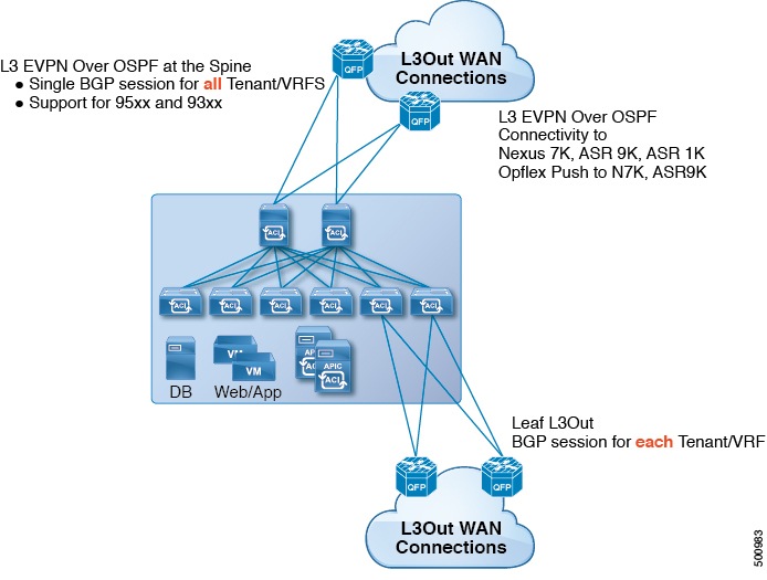
すべてのテナント WAN 接続が、WAN ルータが接続されたスパイン スイッチ上で単一のセッションを使用します。データセンター相互接続ゲートウェイ(DCIG)へのテナント BGP セッションのこの集約では、テナント BGP セッションの数と、それらすべてに必要な設定の量を低減することによって、コントロール プレーンのスケールが向上します。ネットワークは、スパイン ファブリック ポートに設定された L3 サブインターフェイスを使用して拡張されます。ファブリック WAN 経由のレイヤ 3 EVPN サービスを使用した共有サービスによるトランジット ルーティングはサポートされていません。
スパイン スイッチの EVPN 物理接続用の L3Out は、インフラ テナントの下に指定され、次が含まれています。
-
LNodeP(l3extInstP はテナント インフラの L3Out 内では不要)
-
テナント インフラの EVPN 用の L3Out のプロバイダー ラベル
-
OSPF プロトコル ポリシー
-
BGP プロトコル ポリシー
すべての通常テナントが、上記で定義した物理接続を使用します。通常テナントに定義した L3Out のみに次が必要です。
-
l3extConsLbl コンシューマ ラベル。テナント インフラの EVPN 用の L3Out の同じプロバイダー ラベルと一致している必要があります。ラベルの一致により、他のテナント内のアプリケーション EPG が LNodeP 外部 L3Out EPG を消費できます。
-
サブネットとコントラクトを持つ l3extInstP。サブネットの範囲を使用して、ルート制御ポリシーとセキュリティ ポリシーのインポートまたはエクスポートを制御します。
-
テナント インフラ内の一致するプロバイダー L3Out の BGP EVPN は、この L3Out に定義されたテナント ルートをアドバタイズします。
ファブリック WAN ガイドラインと制限事項については、次のレイヤ 3 EVPN サービスを順守します。
-
現時点では、ファブリック WAN 上の単一のレイヤ 3 EVPN サービスのプロバイダー ポリシーのみをファブリック全体のスパイン スイッチ インターフェイスに導入できます。
-
現時点では、レイヤ 3 EVPN はマルチポッドと併せて導入できません。いずれか一方は導入できますが、両方の導入はサポートされていません。
-
スパイン スイッチにレイヤ 3 EVPN の接続を設定する場合、コントロール プレーンの収束を待ってから、別のスパインにレイヤ 3 EVPN を設定します。
-
スパイン スイッチは、複数のプロバイダーのレイヤ 3 EVPN Out に追加できますが、プロバイダー ラベルはレイヤ 3 EVPN ごとに異なる必要があります。また、この例では、OSPF エリアも L3Out ごとに異なる必要があり、異なるループバック アドレスを使用する必要があります。
-
テナント インフラ内の一致するプロバイダー L3Out の BGP EVPN は、この L3Out に定義されたテナント ルートをアドバタイズします。
-
L3 EVPN Out は 3 つ導入できますが、1 つのみに L3 EVPN の prov/cons ラベルを付け、0/0 のエクスポート集約にします。これにより、すべてのルートがエクスポートされます。これは、テナントのリーフ スイッチ上の既存の l3out と同じです。
-
スパイン スイッチとデータセンター相互接続(DCI)ルータ間に直接ピアリングがある場合、リーフ スイッチから ASR へのトランジット ルートにはリーフの PTEP として NH があります。この場合、その ACI ポッドの TEP 範囲に対して ASR の静的ルートを定義します。また、DCI が同じポッドにデュアル ホーム接続されている場合は、静的ルートの優先順位(管理距離)は、他のリンクを通じて受信するルートと同じである必要があります。
-
デフォルトの bgpPeerPfxPol ポリシーはルートを 20k に制限します。レイヤ 3 EVPN ピアについては、必要に応じてこれを増やします。
-
1 つの l3out はプロバイダー ラベル prov1 を持ち、DCI 1 とピアリングしており、もう 1 つの l3out は DCI 2 とピアリングし、プロバイダー ラベル prov2 を持っている 2 つの l3outs の 1 つのスパインでの導入シナリオで、テナント VRF にプロバイダー ラベルのいずれか(prov1 または prov2)を指しているコンシューマ ラベルがある場合は、テナント ルートが DCI 1 と DCI 2 の両方に送信されます。
NX-OS スタイルの CLI を使用した WAN サービス用のレイヤ 3 EVPN の設定
次に、任意のテナント ネットワークが使用できるインフラ レイヤ 3 EVPN WAN サービスを設定する手順について説明します。
| ステップ 1 |
テナント インフラに BGP EVPN を設定します。これには、VRF の導入、インターフェイスの IP アドレッシング、OSPF および BGP の設定が含まれます。 例: ifav201-ifc1(config-spine)# sh runn
# Command: show running-config spine 111
# Time: Tue Jun 14 19:36:49 2016
spine 111
# Configure Tenant Infra VRF overlay-1 on the spine.
vrf context tenant infra vrf overlay-1
router-id 10.10.3.3
exit
# Configure Interface.
interface ethernet 1/33
vlan-domain member golf_dom
exit
interface ethernet 1/33.4
vrf member tenant infra vrf overlay-1
mtu 1500
ip address 5.0.0.1/24
ip router ospf default area 0.0.0.150
exit
interface ethernet 1/34
vlan-domain member golf_dom
exit
interface ethernet 1/34.4
vrf member tenant infra vrf overlay-1
mtu 1500
ip address 2.0.0.1/24
ip router ospf default area 0.0.0.200
exit
# Configure OSPF
router ospf default
vrf member tenant infra vrf overlay-1
area 0.0.0.150 loopback 10.10.5.3
area 0.0.0.200 loopback 10.10.4.3
exit
exit
#Configure BGP
router bgp 100
vrf member tenant infra vrf overlay- 1
neighbor 10.10.4.1 evpn
label golf_aci
update-source loopback 10.10.4.3
remote-as 100
exit
neighbor 10.10.5.1 evpn
label golf_aci2
update-source loopback 10.10.5.3
remote-as 100
exit
exit
exit
|
| ステップ 2 |
テナント設定。これには、route-target、route-map、prefix-epg の設定が含まれます。 例: # Tenant BD configuration - Gateway subnet which will be advertised through BGP EVPN session.
tenant sky
vrf context vrf_sky
exit
bridge-domain bd_sky
vrf member vrf_sky
exit
interface bridge-domain bd_sky
ip address 59.10.1.1/24
exit
bridge-domain bd_sky2
vrf member vrf_sky
exit
interface bridge-domain bd_sky2
ip address 59.11.1.1/24
exit
exit
# Setting up the route-map to advertise the BD subnet through BGP EVPN Sessions.
# In this example each BD is advertised via a different BGP evpn session on the spine.
# Each BGP Session is identified by a unique provider label.
spine 111
vrf context tenant sky vrf vrf_sky
address-family ipv4 unicast
route-target export 100:1
route-target import 100:1
exit
route-map rmap
ip prefix-list p1 permit 11.10.10.0/24 #Prefix learnt from a Transit Network.
match bridge-domain bd_sky
exit
match prefix-list p1
exit
evpn export map rmap label golf_aci
route-map rmap2
match bridge-domain bd_sky
exit
match prefix-list p1
exit
exit
evpn export map rmap label golf_aci2
external-l3 epg l3_sky
vrf member vrf_sky
match ip 80.10.1.0/24
exit
|
マルチポッド ファブリックについて
マルチポッドは、隔離されたコントロール プレーン プロトコルを持つ複数のポッドで構成された、障害耐性の高いファブリックのプロビジョニングを可能にします。また、マルチポッドでは、さらに柔軟にリーフとスパイン スイッチ間のフル メッシュ配線を行うことができます。たとえば、リーフ スイッチが異なるフロアや異なる建物にまたがって分散している場合、マルチポッドでは、フロアごと、または建物ごとに複数のポッドをプロビジョニングし、スパイン スイッチを通じてポッド間を接続することができます。
マルチポッドは、異なるポッド内のスパイン間の通信にポッド間ネットワーク(IPN)で OSPF を介した BGP EVPN プロトコルを使用します。WAN ルータは、スパイン スイッチに直接接続されるか、またはボーダー リーフ スイッチに接続された IPN 内でプロビジョニングできます。マルチポッドはすべてのポッドに単一の APIC クラスタを使用します。そのため、すべてのポッドが単一のファブリックとして機能します。ポッド全体にわたって個々の APIC コントローラが配置されますが、それらはすべて単一の APIC クラスタの一部です。
マルチポッド ファブリックでのスイッチの割り当て
ノード グループ ポリシーと L3Out ポリシーがすでに作成されています。
| コマンドまたはアクション | 目的 | |
|---|---|---|
| ステップ 1 | configure 例: apic1# configure |
グローバル コンフィギュレーション モードを開始します。 |
| ステップ 2 | [no]systemswitch-idserial-numberswitch-idswitch-name [podpod-id] [role {leaf | spine}] 例: apic1(config)# system switch-id SAL1748H56D 201 ifav4-spine1 pod 1 role spine |
マルチポッド ファブリック内の各スイッチに対して、スイッチの関連するポッドとロール(リーフ/スパイン)を宣言します。マルチポッド ファブリック内の各リーフとスパイン スイッチにこのコマンドを繰り返します。 |
| ステップ 3 | [no]systempodpod-idtep-poolip-prefix/length 例: apic1(config)# system pod 1 tep-pool 10.0.0.0/16 |
ポッドにトンネル エンドポイント IP アドレス プールを設定します。マルチポッド ファブリック内の各ポッドにこのコマンドを繰り返します。 |
次に、2 ポッド ファブリックでスパインとリーフ スイッチを割り当てる例を示します。
apic1# configure
apic1(config)# system switch-id SAL1748H56D 201 ifav4-spine1 pod 1 role spine
apic1(config)# system switch-id SAL1938P7A6 202 ifav4-spine3 pod 1 role spine
apic1(config)# system switch-id SAL1819RXP4 101 ifav4-leaf1 pod 1 role leaf
apic1(config)# system switch-id SAL1803L25H 102 ifav4-leaf2 pod 1 role leaf
apic1(config)# system switch-id SAL1934MNY0 103 ifav4-leaf3 pod 1 role leaf
apic1(config)# system switch-id SAL1934MNY3 104 ifav4-leaf4 pod 1 role leaf
apic1(config)# system switch-id SAL1931LA3B 203 ifav4-spine2 pod 2 role spine
apic1(config)# system switch-id FGE173400A9 204 ifav4-spine4 pod 2 role spine
apic1(config)# system switch-id SAL1938PHBB 105 ifav4-leaf5 pod 2 role leaf
apic1(config)# system switch-id SAL1942R857 106 ifav4-leaf6 pod 2 role leaf
apic1(config)# system pod 1 tep-pool 10.0.0.0/16
apic1(config)# system pod 2 tep-pool 10.1.0.0/16
ファブリックの外部接続を設定します。
マルチポッド ファブリックのファブリックの外部接続の設定
-
ノード グループ ポリシーと L3Out ポリシーがすでに作成されています。
-
スイッチがポッドに割り当てられています。
| コマンドまたはアクション | 目的 | |
|---|---|---|
| ステップ 1 | configure 例: apic1# configure |
グローバル コンフィギュレーション モードを開始します。 |
| ステップ 2 | [no]fabric-externalcontroller-number 例: apic1(config)# fabric-external 1 |
|
| ステップ 3 | [no]bgpevpnpeering [passwordpeering-password] [type {automatic_with_full_mesh | automatic_with_rr}] 例: apic1(config-fabric-external)# bgp evpn peering |
BGP EVPN ピアリング プロファイルを設定します。ピアリング パスワードを設定できます。また、タイプはフル メッシュに設定するか、ルータ リフレクタで設定できます。 |
| ステップ 4 | [no]podpod-id 例: apic1(config-fabric-external)# pod 1 |
設定用のポッドを選択します。 |
| ステップ 5 | [no]interpoddatahardware-proxyip-addr/mask 例: apic1(config-fabric-external-pod)# interpod data hardware-proxy 100.11.1.1/32 |
ポッド間トラフィックの各ポートにエニーキャスト ハードウェア プロキシ IP アドレスを設定します。 |
| ステップ 6 | [no]bgpevpnpeering [passwordpeering-password] [type {automatic_with_full_mesh | automatic_with_rr}] 例: apic1(config-fabric-external-pod)# bgp evpn peering |
|
| ステップ 7 | exit 例: apic1(config-fabric-external-pod)# exit |
BGP EVPN ピアリング プロファイルの設定に戻ります。 |
| ステップ 8 | マルチポッド ファブリック内の各ポッドにステップ 4 ~ 7 を繰り返します。 | |
| ステップ 9 | [no]route-mapinterpod-import 例: apic1(config-fabric-external)# route-map interpod-import |
OSPF プロトコルを介してファブリック内への参加を許可されるポッド間ネットワーク(IPN)のサブネットを含むルート マップを設定します。 |
| ステップ 10 | [no]ipprefix-listprefix-list-name [permitip-address/len 例: apic1(config-fabric-external-route-map)# ip prefix-list default permit 0.0.0.0/0 |
|
| ステップ 11 | exit 例: apic1(config-fabric-external-route-map)# exit |
ファブリック外コンフィギュレーション モードに戻ります。 |
| ステップ 12 | [no]route-targetextendedASN4:NN 例: apic1(config-fabric-external)# route-target extended 5:16 |
ルート ターゲットは拡張コミュニティ属性として伝送されます。AA4:NN2 形式でコミュニティ番号を入力します(1-4294967295: 1-65535)。 |
| ステップ 13 | exit |
次に、マルチポッド ファブリックにファブリック外部接続を設定する例を示します。
apic1# configure
apic1(config)# fabric-external 1
apic1(config-fabric-external)# bgp evpn peering
apic1(config-fabric-external)# pod 1
apic1(config-fabric-external-pod)# interpod data hardware-proxy 100.11.1.1/32
apic1(config-fabric-external-pod)# bgp evpn peering
apic1(config-fabric-external-pod)# exit
apic1(config-fabric-external)# pod 2
apic1(config-fabric-external-pod)# interpod data hardware-proxy 200.11.1.1/32
apic1(config-fabric-external-pod)# bgp evpn peering
apic1(config-fabric-external-pod)# exit
apic1(config-fabric-external)# route-map interpod-import
apic1(config-fabric-external-route-map)# ip prefix-list default permit 0.0.0.0/0
apic1(config-fabric-external-route-map)# exit
apic1(config-fabric-external)# route-target extended 5:16
apic1(config-fabric-external)# exit
スパイン インターフェイスおよび OSPF を設定します。
マルチポッド ファブリックのスパイン インターフェイスと OSPF の設定
-
スイッチがポッドに割り当てられています。
-
VLAN ドメインが存在している必要があります。
| コマンドまたはアクション | 目的 | |
|---|---|---|
| ステップ 1 | configure 例: apic1# configure |
グローバル コンフィギュレーション モードを開始します。 |
| ステップ 2 | spinespine-id 例: apic1(config)# spine 104 |
スパイン スイッチは、101 ~ 4000 の範囲内の ID 番号か、または「spine1」などの名前で指定できます。 |
| ステップ 3 | [no]vrfcontexttenantinfravrfvrf-name 例: apic1(config-spine)# vrf context tenant infra vrf overlay-1 |
|
| ステップ 4 | [no]router-idA.B.C.D 例: apic1(config-spine-vrf)# router-id 201.201.201.201 |
ルータ識別子(ID)を設定します。 |
| ステップ 5 | exit 例: apic1(config-spine-vrf)# exit |
スパイン コンフィギュレーション モードに戻ります。 |
| ステップ 6 | [no]interfaceethernetslot/port 例: apic1(config-spine)# interface ethernet 1/1 |
|
| ステップ 7 | [no]vlan-domainmemberdomain-name 例: apic1(config-spine)# vlan-domain member l3Dom |
VLAN ドメインは、グローバル コンフィギュレーション モードで vlan-domaindomain-name コマンドを使用して作成されており、すでに存在している必要があります。 |
| ステップ 8 | exit 例: apic1(config-spine-if)# exit |
スパイン コンフィギュレーション モードに戻ります。 |
| ステップ 9 | [no]interfaceethernettype/slot.subinterface 例: apic1(config-spine)# interface ethernet 1/1.4 |
サブインターフェイスのカプセル化は 4 である必要があります。 |
| ステップ 10 | [no]vrfmembertenantinfravrfvrf-name 例: apic1(config-spine-if)# vrf member tenant infra vrf overlay-1 |
テナント VRF のメンバーとしてインターフェイスを設定します。 |
| ステップ 11 | [no]ipaddressip-address 例: apic1(config-spine-if)# ip address 201.1.1.1/30 |
|
| ステップ 12 | [no]iprouterospfdefaultarea0.0.0.0 例: apic1(config-spine-if)# ip router ospf default area 0.0.0.0 |
|
| ステップ 13 | [no]ipospfcostcost 例: apic1(config-spine-if)# ip ospf cost 1 |
|
| ステップ 14 | exit 例: apic1(config-spine-if)# exit |
スパイン コンフィギュレーション モードに戻ります。 |
| ステップ 15 | ステップ 6 ~ ステップ 14 を繰り返し、他のインターフェイスを追加します。 | |
| ステップ 16 | [no]routerospfdefault 例: apic1(config-spine)# router ospf default |
|
| ステップ 17 | [no]vrfmembertenantinfravrfvrf-name 例: apic1(config-spine-ospf)# vrf member tenant infra vrf overlay-1 |
|
| ステップ 18 | [no]areaarealoopbackip-address 例: apic1(config-spine-ospf-vrf)# area 0.0.0.0 loopback 201.201.201.201 |
OSPF を介してループバック アドレスをアドバタイズします。このアドレスは、ピアリングの場合に BGP EVPN セッションで使用されます。 |
| ステップ 19 | [no]areaareainterpodpeering 例: apic1(config-spine-ospf-vrf)# area 0.0.0.0 interpod peering |
OSPF エリアでポッド間ピアリングを有効にし、OSPF によってアドバタイズされたループバック アドレスを使用して BGP EVPN セッションを自動的に設定します。 |
| ステップ 20 | exit 例: apic1(config-spine-ospf-vrf)# exit |
OSPF コンフィギュレーション モードに戻ります。 |
| ステップ 21 | exit 例: apic1(config-spine-ospf)# exit |
スパイン コンフィギュレーション モードに戻ります。 |
| ステップ 22 | exit 例: apic1(config-spine)# exit |
グローバル コンフィギュレーション モードに戻ります。 |
| ステップ 23 | ステップ 2 ~ ステップ 22 を繰り返し、他のスパイン スイッチを設定します。 |
apic1# configure

    # CONFIGURE FIRST SPINE

apic1(config)# spine 201
apic1(config-spine)# vrf context tenant infra vrf overlay-1
apic1(config-spine-vrf)# router-id 201.201.201.201
apic1(config-spine-vrf)# exit

apic1(config-spine)# interface ethernet 1/1
apic1(config-spine-if)# vlan-domain member l3Dom
apic1(config-spine-if)# exit
apic1(config-spine)# interface ethernet 1/1.4
apic1(config-spine-if)# vrf member tenant infra vrf overlay-1
apic1(config-spine-if)# ip address 201.1.1.1/30
apic1(config-spine-if)# ip router ospf default area 0.0.0.0
apic1(config-spine-if)# ip ospf cost 1
apic1(config-spine-if)# exit

apic1(config-spine)# interface ethernet 1/2
apic1(config-spine-if)# vlan-domain member l3Dom
apic1(config-spine-if)# exit
apic1(config-spine)# interface ethernet 1/2.4
apic1(config-spine-if)# vrf member tenant infra vrf overlay-1
apic1(config-spine-if)# ip address 201.2.1.1/30
apic1(config-spine-if)# ip router ospf default area 0.0.0.0
apic1(config-spine-if)# ip ospf cost 1
apic1(config-spine-if)# exit

apic1(config-spine)# router ospf default
apic1(config-spine-ospf)# vrf member tenant infra vrf overlay-1
apic1(config-spine-ospf-vrf)# area 0.0.0.0 loopback 201.201.201.201
apic1(config-spine-ospf-vrf)# area 0.0.0.0 interpod peering
apic1(config-spine-ospf-vrf)# exit
apic1(config-spine-ospf)# exit
apic1(config-spine)# exit

    # CONFIGURE SECOND SPINE

apic1(config)# spine 202
apic1(config-spine)# vrf context tenant infra vrf overlay-1
apic1(config-spine-vrf)# router-id 202.202.202.202
apic1(config-spine-vrf)# exit

apic1(config-spine)# interface ethernet 1/2
apic1(config-spine-if)# vlan-domain member l3Dom
apic1(config-spine-if)# exit
apic1(config-spine)# interface ethernet 1/2.4
apic1(config-spine-if)# vrf member tenant infra vrf overlay-1
apic1(config-spine-if)# ip address 202.1.1.1/30
apic1(config-spine-if)# ip router ospf default area 0.0.0.0
apic1(config-spine-if)# ip ospf cost 1
apic1(config-spine-if)# exit

apic1(config-spine)# router ospf default
apic1(config-spine-ospf)# vrf member tenant infra vrf overlay-1
apic1(config-spine-ospf-vrf)# area 0.0.0.0 loopback 202.202.202.202
apic1(config-spine-ospf-vrf)# area 0.0.0.0 interpod peering
apic1(config-spine-ospf-vrf)# exit
apic1(config-spine-ospf)# exit
apic1(config-spine)# exit

    # CONFIGURE ADDITIONAL SPINES
 フィードバック