Catalyst スイッチ間の 802.1Q トランキングの設定
ダウンロード オプション
偏向のない言語
この製品のドキュメントセットは、偏向のない言語を使用するように配慮されています。このドキュメントセットでの偏向のない言語とは、年齢、障害、性別、人種的アイデンティティ、民族的アイデンティティ、性的指向、社会経済的地位、およびインターセクショナリティに基づく差別を意味しない言語として定義されています。製品ソフトウェアのユーザインターフェイスにハードコードされている言語、RFP のドキュメントに基づいて使用されている言語、または参照されているサードパーティ製品で使用されている言語によりドキュメントに例外が存在する場合があります。シスコのインクルーシブ ランゲージの取り組みの詳細は、こちらをご覧ください。
翻訳について
シスコは世界中のユーザにそれぞれの言語でサポート コンテンツを提供するために、機械と人による翻訳を組み合わせて、本ドキュメントを翻訳しています。ただし、最高度の機械翻訳であっても、専門家による翻訳のような正確性は確保されません。シスコは、これら翻訳の正確性について法的責任を負いません。原典である英語版(リンクからアクセス可能)もあわせて参照することを推奨します。
はじめに
このドキュメントでは、Cisco IOS®ソフトウェアを実行しているCisco Catalystスイッチ間でのIEEE 802.1Q(dot1q)トランキングの違いについて説明します。
前提条件
要件
この設定を行う前に、次の要件が満たされていることを確認します。
-
IEEE 802.1Q トランキングの知識
-
コマンドラインインターフェイス(CLI)を使用したCatalyst 3560およびCatalyst 6500シリーズスイッチの設定に関する知識
使用するコンポーネント
このドキュメントの情報は、次のソフトウェアとハードウェアのバージョンに基づいています。
-
Cisco IOS ソフトウェア リリース 12.2(25)SEA が稼働する Catalyst 3560 スイッチ
-
Cisco IOS ソフトウェア リリース 12.1(26)E1 が稼働する Catalyst 6509 スイッチ
このドキュメントの情報は、特定のラボ環境にあるデバイスに基づいて作成されました。このドキュメントで使用するすべてのデバイスは、クリアな(デフォルト)設定で作業を開始しています。本稼働中のネットワークでは、各コマンドによって起こる可能性がある影響を十分確認してください。
背景説明
このドキュメントでは、Cisco IOS®ソフトウェアが稼働するCisco Catalyst 3560スイッチとCatalyst 6500シリーズスイッチ間でのIEEE 802.1Q(dot1q)トランキングの設定例を紹介します。トランキングとは、複数の VLAN からのトラフィックを、2 台のデバイス間のポイントツーポイント リンクで伝送する方法です。
レガシープラットフォームでは、イーサネットトランキングを実装する方法は2つありました。
-
Inter-Switch Link(ISL; スイッチ間リンク):プロトコルシスコ独自のプロトコル
-
802.1Q:IEEE 標準
Catalystコンポーネント
このドキュメントのCatalyst 3560と6500の設定は、Cisco IOSソフトウェアが稼働する他のCatalystスイッチにも適用できます。
注:さまざまなCatalystスイッチでサポートされているトランキング方式については、次のドキュメントを参照してください。
-
Catalystスイッチでトランキングを実装するためのシステム要件
注:このドキュメントで紹介しているのは、スイッチのコンフィギュレーションファイルと、それに関連する show コマンド使用例の出力だけです。Catalystスイッチ間で802.1Qトランクを設定する方法の詳細については、次のドキュメントを参照してください。
背景理論
IEEE 802.1Q では、内部的なタギング機構を使用しています。トランキング デバイスは 4 バイトのタグを挿入して、フレームが所属する VLAN を識別し、Frame Check Sequence(FCS; フレーム チェック シーケンス)を再計算します。詳細については、次のドキュメントを参照してください。
注:次に、この設定に関する重要な注意事項を示します。
-
Catalyst 3560/3750シリーズスイッチ上のイーサネットインターフェイスはすべて、802.1QおよびISLカプセル化をサポートできます。Catalyst 3550 スイッチのイーサネット インターフェイスは、デフォルトではレイヤ 2(L2)ポートです。
-
Catalyst 6500/6000 シリーズ スイッチのすべてのイーサネット ポートでは、802.1Q および ISL のカプセル化がサポートされています。
-
デフォルトでは、Cisco IOS ソフトウェアを実行する Catalyst 4500 シリーズ スイッチは、ISL と 802.1Q の両トランキング モードをサポートしています。これらのトランキング モードは、WS-X4418-GB モジュールおよび WS-X4412-2GB-T モジュールのブロッキング ギガビット ポート以外のすべてのインターフェイスでサポートされています。これらのポートはISLをサポートせず、802.1Qトランキングのみをサポートします。WS-X4418-GB モジュールのポート 3 ~ 18 はブロッキング ギガビット ポートです。WS-X4412-2GB-T モジュールのポート 1 ~12 はブロッキング ギガビット ポートです。
注:ポートは、バックプレーンへの接続が加入過多の場合はブロッキングポートになります。
-
Catalyst 6500プラットフォームとCatalyst 4500プラットフォームの主な違いは、デフォルトのインターフェイス設定です。Cisco IOSソフトウェアが稼働するCatalyst 6500スイッチには、デフォルトでレイヤ3(L3)ルーテッドポートであるシャットダウンモードのインターフェイスがあります。Cisco IOSソフトウェアが稼働するCatalyst 4500スイッチでは、すべてのインターフェイスがイネーブルになっています。これらのインターフェイスは、デフォルトで L2 スイッチ ポートです。
-
Catalyst 3750スイッチのトランクインターフェイスで802.1Qカプセル化が使用されている場合、
show interface の出力にラントが表示される場合があります。これは、qタグを含む61 ~ 64バイトでカプセル化された有効な802.1Qパケットが、正しく転送されていても、Catalyst 3750スイッチではサイズの小さいフレームとしてとしてカウントされるためです。
注:Cisco IOS XEを実行する最新のCatalystスイッチ(3650/3850以降など)では、ISLプロトコルがサポートされなくなったことに注意してください。
設定
設定このセクションでは、このドキュメントで説明する機能を設定するために必要な情報を提供しています。
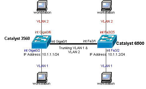
ネットワーク図
ネットワーク図このドキュメントでは、次のネットワーク セットアップを使用します。
注:Catalyst 3560のギガビットイーサネットインターフェイスは、10/100/1000 Mbpsのネゴシエートされたイーサネットインターフェイスです。そのため、このネットワーク図では、Catalyst 3560 のギガビット ポートは Catalyst 6500 のファスト イーサネット(100 Mbps)ポートに接続されています。
 ネットワーク図
コンフィギュレーション
コンフィギュレーションこのドキュメントでは、次のコンフィギュレーションを使用します。
| Catalyst 3560 スイッチ |
|---|
!--- Notice: This example creates VLAN 1 and VLAN 2 |
| Catalyst 6500 スイッチ |
|---|
!--- Notice: This example creates VLAN 1 and VLAN 2 and sets |
注:存在しないVLANにインターフェイスを割り当てると、VLANデータベースにVLANを作成するまで、インターフェイスはシャットダウンします。詳細については、『VLAN の設定』の「イーサネット VLAN の作成または変更」のセクションを参照してください。
確認
確認このセクションでは、設定が正常に動作していることを確認します。Catalyst 3560/3750/6500/4500 スイッチでは、次のコマンドを使用します。
-
show interfaces <interface_type module/port> trunk(トランクインターフェイスの表示)
-
show interfaces <interface_type module/port> switchport(隠しコマンド)
-
show vlan
-
show vtp status
コマンドのサンプル出力 show
コマンドのサンプル出力 show Catalyst 3560 スイッチ
Catalyst 3560 スイッチ-
show interfaces <interface_type module/por> trunk:このコマンドは、インターフェイスのトランク設定と、トラフィックをトランクで送信できるVLAN番号を表示します。
3560#show interface gigabitethernet 0/1 trunk Port Mode Encapsulation Status Native vlan Gi0/1 on 802.1q trunking 1 Port Vlans allowed on trunk Gi0/1 1 4094 Port Vlans allowed and active in management domain Gi0/1 1-2 Port Vlans in spanning tree forwarding state and not pruned Gi0/1 1-2
-
show interfaces <interface_type module/port> switchport:このコマンドは、インターフェイスのスイッチポート設定を表示します。
この表示で、Operational Mode フィールドと Operational Trunking Encapsulation フィールドを確認します。
3560#show interface gigabitethernet 0/1 switchport Name: Gi0/1 Switchport: Enabled Administrative Mode: trunk Operational Mode: trunk Administrative Trunking Encapsulation: dot1q Operational Trunking Encapsulation: dot1q Negotiation of Trunking: On Access Mode VLAN: 1 (default) Trunking Native Mode VLAN: 1 (default) Voice VLAN: none Administrative private-vlan host-association: none Administrative private-vlan mapping: none Administrative private-vlan trunk native VLAN: none Administrative private-vlan trunk encapsulation: dot1q Administrative private-vlan trunk normal VLANs: none Administrative private-vlan trunk private VLANs: none Operational private-vlan: none Trunking VLANs Enabled: ALL Pruning VLANs Enabled: 2-1001 Capture Mode Disabled Capture VLANs Allowed: ALL Protected: false Unknown unicast blocked: disabled Unknown multicast blocked: disabled Appliance trust : none
-
show vlan:このコマンドは、VLANと特定のVLANに属しているポートに関する情報を表示します。
3560#show vlan VLAN Name Status Ports ---- -------------------------------- --------- ------------------------------- 1 default active Gi0/2, Gi0/3, Gi0/4, Gi0/5 2 VLAN0002 active Gi0/6, Gi0/7, Gi0/8, Gi0/9 Gi0/10, Gi0/11, Gi0/12 1002 fddi-default act/unsup 1003 token-ring-default act/unsup 1004 fddinet-default act/unsup 1005 trnet-default act/unsup !--- Output suppressed.注:出力に表示されるポートは、アクセスポートだけです。ただし、show vlanの出力には、トランクとして設定されているポートと、notconnectedステータスにあるポートも表示されます。
-
  show vtp status:このコマンドは、VTP管理ドメイン、ステータス、カウンタに関する一般情報を表示します。

        3560#show vtp status
VTP Version : 2
Configuration Revision : 0
Maximum VLANs supported locally : 1005
Number of existing VLANs : 6
VTP Operating Mode : Transparent
VTP Domain Name :
VTP Pruning Mode : Disabled
VTP V2 Mode : Disabled
VTP Traps Generation : Disabled
MD5 digest : 0x4A 0x55 0x17 0x84 0xDB 0x99 0x3F 0xD1
Configuration last modified by 10.1.1.1 at 0-0-00 00:00:00

3560#ping 10.1.1.2
Type escape sequence to abort.
Sending 5, 100-byte ICMP Echos to 10.1.1.2, timeout is 2 seconds:
!!!!!
Success rate is 100 percent (5/5), round-trip min/avg/max = 1/1/4 ms
3560#
Catalyst 6500 スイッチ
Catalyst 6500 スイッチ-
show interfaces <interface_type module/port> trunk:このコマンドは、インターフェイスのトランク設定と、トラフィックをトランクで送信できるVLAN番号を表示します。
 Cat6500#show interfaces fastethernet 3/1 trunk

Port      Mode         Encapsulation  Status        Native vlan
Fa3/1     on           802.1q         trunking      1

Port      Vlans allowed on trunk
Fa3/1     1 4094

Port      Vlans allowed and active in management domain
Fa3/1     1-2

Port      Vlans in spanning tree forwarding state and not pruned
Fa3/1     1-2
-
show interfaces <interface_type module/port> switchport:このコマンドは、インターフェイスのスイッチポート設定を表示します。 この表示で、Operational Mode フィールドと Operational Trunking Encapsulation フィールドを確認します。
 cat6500#show interface fastethernet 3/1 switchport
Name: Fa3/1
Switchport: Enabled
Administrative Mode: trunk
Operational Mode: trunk
Administrative Trunking Encapsulation: dot1q
Operational Trunking Encapsulation: dot1q
Negotiation of Trunking: On
Access Mode VLAN: 1 (default)
Trunking Native Mode VLAN: 1 (default)
Voice VLAN: none
Administrative private-vlan host-association: none
Administrative private-vlan mapping: none
Administrative private-vlan trunk native VLAN: none
Administrative private-vlan trunk encapsulation: dot1q
Administrative private-vlan trunk normal VLANs: none
Administrative private-vlan trunk private VLANs: none
Operational private-vlan: none
Trunking VLANs Enabled: ALL
Pruning VLANs Enabled: 2-1001
Capture Mode Disabled
Capture VLANs Allowed: ALL
-
show vlan:このコマンドは、VLAN と特定の VLAN に属しているポートに関する情報を表示します。
 Cat6500#show vlan

VLAN Name                             Status    Ports
---- -------------------------------- --------- -------------------------------
1    default                          active    Fa3/2, Fa3/3, Fa3/4, Fa3/5
                                                Fa3/6, Fa3/7, Fa3/8, Fa3/9
                                                Fa3/10, Fa3/11, Fa3/12, Fa3/13
                                                Fa3/14, Fa3/15, Fa3/16, Fa3/17
                                                Fa3/18, Fa3/19, Fa3/20, Fa3/21
                                                Fa3/22, Fa3/23, Fa3/24
2    VLAN0002                         active    Fa3/25, Fa3/26, Fa3/27, Fa3/28
                                                Fa3/29, Fa3/30, Fa3/31, Fa3/32
                                                Fa3/33, Fa3/34, Fa3/35, Fa3/36
                                                Fa3/37, Fa3/38, Fa3/39, Fa3/40
                                                Fa3/41, Fa3/42, Fa3/43, Fa3/44
                                                Fa3/45, Fa3/46, Fa3/47, Fa3/48
1002 fddi-default                      act/unsup
1003 token-ring-default                act/unsup
1004 fddinet-default                   act/unsup
1005 trnet-default                     act/unsup
注:表示されるポートは、レイヤ2非トランク(アクセス)ポートとして設定したポートだけです。show vlanの出力には、トランクとして設定されているポートと、notconnectedステータスにあるポートも表示されます。詳細は、『レイヤ2スイッチング用のLANポートの設定』の「レイヤ2スイッチング用のLANインターフェイスの設定」セクションを参照してください。
-
show vtp status:このコマンドは、VTP管理ドメイン、ステータス、カウンタに関する一般情報を表示します。
Cat6500#show vtp status VTP Version : 2 Configuration Revision : 0 Maximum VLANs supported locally : 1005 Number of existing VLANs : 6 VTP Operating Mode : Transparent VTP Domain Name : VTP Pruning Mode : Disabled VTP V2 Mode : Disabled VTP Traps Generation : Disabled MD5 digest : 0xBF 0x86 0x94 0x45 0xFC 0xDF 0xB5 0x70 Configuration last modified by 10.1.1.2 at 0-0-00 00:00:00
-
ping
Cat6500#ping 10.1.1.1 Type escape sequence to abort. Sending 5, 100-byte ICMP Echos to 10.1.1.1, timeout is 2 seconds: !!!!! Success rate is 100 percent (5/5), round-trip min/avg/max = 1/1/4 ms
関連情報
関連情報 更新履歴
| 改定 | 発行日 | コメント |
|---|---|---|
3.0 |
07-Jun-2024 |
更新された書式。 |
2.0 |
19-Jan-2023 |
書式を更新します。CCWアラートを修正します。再認定 |
1.0 |
29-Nov-2001 |
初版 |
 フィードバック