はじめに
このドキュメントでは、BGPコミュニティ値を使用して、アップストリームプロバイダーネットワークのルーティングポリシーを制御する方法について説明します。
前提条件
要件
このドキュメントを読むには、ボーダーゲートウェイプロトコル(BGP)ルーティングプロトコルとその動作を理解している必要があります。
使用するコンポーネント
このドキュメントの内容は、特定のソフトウェアやハードウェアのバージョンに限定されるものではありません。ただし、このドキュメントの情報は、次のソフトウェアバージョンに基づくものです。
このドキュメントの情報は、特定のラボ環境にあるデバイスに基づいて作成されました。このドキュメントで使用するすべてのデバイスは、クリアな(デフォルト)設定で作業を開始しています。本稼働中のネットワークでは、各コマンドによって起こる可能性がある影響を十分確認してください。
背景説明
コミュニティ自体はBGPベストパス(BGP)プロセスを変更しませんが、コミュニティは一連のルートをマークするためのフラグとして使用できます。アップストリームサービスプロバイダールータは、これらのフラグを使用して、ネットワーク内の特定のルーティングポリシー(ローカルプリファレンスなど)を適用できます。
プロバイダーは、設定可能なコミュニティ値と対応するローカルプリファレンス値をプロバイダーネットワーク内でマッピングします。プロバイダーネットワークセット内のLOCAL_PREFの変更を必要とする特定のポリシーを設定し、ルーティング更新で対応するコミュニティ値を設定できます。
コミュニティは、共通のプロパティを共有するプレフィックスのグループであり、BGP コミュニティ属性で設定できます。BGP コミュニティ属性は、可変長のオプショナル通過属性属性です。この属性は、コミュニティを指定する 4 つのオクテット値で構成されます。コミュニティアトリビュート値は、最初の2つのオクテットが自律システム(AS)番号でエンコードされ、残りの2つのオクテットはASによって定義されます。プレフィックスには、複数のコミュニティ属性を設定できます。プレフィクス内の複数のコミュニティアトリビュートを認識するBGPスピーカは、1つ、一部、またはすべてのアトリビュートに基づいて動作できます。ルータは、他のピアに属性を渡す前に、コミュニティ属性を追加または変更することもできます。コミュニティ属性の詳細については、『BGP 導入事例』を参照してください。
ローカルプリファレンスアトリビュートは、特定のネットワークに到達するために優先されるパスをASに示します。同じ宛先へのパスが複数ある場合は、優先順位の高いパスが選択されます(local preference属性のデフォルト値は100)。 詳細については、「ケーススタディ」を参照してください。
表記法
表記法の詳細については、『シスコ テクニカル ティップスの表記法』を参照してください。
ルーティングポリシーの設定と制御
注:このドキュメントで使用されているコマンドの詳細を調べるには、Command Lookup Toolを使用してください。
単純化するため、コミュニティアトリビュートとローカルプリファレンスアトリビュートマッピングは、アップストリームサービスプロバイダー(AS 100)とデバイス(AS 30)の間で確立されるものと仮定します。
|
ローカル設定
|
コミュニティ値
|
|
130
|
100:300
|
|
125
|
100:250
|
プレフィックスが100:300と等しいコミュニティアトリビュートでアナウンスされる場合、アップストリームサービスプロバイダーは、コミュニティアトリビュートが100:250と等しい場合、これらのルートのローカルプリファレンスを130と125に設定します。
これにより、サービスプロバイダーにアナウンスされたプレフィクスのコミュニティ値を変更した場合に、サービスプロバイダーネットワーク内のルーティングポリシーを制御できます。
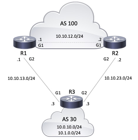
次のネットワーク図(NETWORKS)では、AS 30はコミュニティアトリビュートでこのルーティングポリシーを使用することを求めています。
このルーティングポリシーを実現するために、R3は次の方法でプレフィックスをアナウンスします。
R1 に対して:
- 10.0.10.0/24 とコミュニティ属性 100:300
- 10.1.0.0/24 とコミュニティ属性 100:250
R2 に対して:
BGPネイバーR1およびR2はR3からプレフィックスを受信すると、R1およびR2はコミュニティアトリビュートとローカルプリファレンスアトリビュート間のマッピングに基づいて設定されたポリシー(上記の表を参照)を適用し、それによって指定されたルーティングポリシー(AS 30)を実現します。 R1 は BGP テーブルにプレフィックスをインストールします。
R2 は BGP テーブルにプレフィックスをインストールします。
BGP パス選択条件では高いローカル設定が優先されるため、ローカル設定が 130 のパスが(130 は 125 より大きいため)AS 100 内のベスト パスとして選択され、R1 および R2 の IP ルーティング テーブルにインストールされます。BGP パスの選択基準の詳細については、『BGP でベスト パスを選択するアルゴリズム』を参照してください。
ネットワーク図
コンフィギュレーション
このドキュメントでは、次のコンフィギュレーションを使用します。
| R3 の設定 |
hostname R3
!
interface Loopback0
 ip address 10.0.10.1 255.255.255.0
!
interface Loopback1
 ip address 10.1.0.1 255.255.255.0
!
interface GigabitEthernet1
 ip address 10.10.13.3 255.255.255.0

!--- Interface connected to R1
!
interface GigabitEthernet2
 ip address 10.10.23.3 255.255.255.0

!--- Interface connected to R2
!
router bgp 30
 bgp router-id interface Loopback0
 network 10.0.10.0 mask 255.255.255.0
 network 10.1.0.0 mask 255.255.255.0

!--- Network commands announce prefix 10.0.10.0/24 and 10.1.0.0/24.

 neighbor 10.10.13.1 remote-as 100

!--- Establishes peering with R1

 neighbor 10.10.13.1 send-community

!--- Without this command, the community attributes are not sent to the neighbor

 neighbor 10.10.13.1 route-map Peer-R1 out

!--- Configures outbound policy as defined by route-map "Peer-R1" when peering with R1

 neighbor 10.10.23.2 remote-as 100

!--- Establishes peering with R2

 neighbor 10.10.23.2 send-community

!--- Configures to send community attribute to R2

 neighbor 10.10.23.2 route-map Peer-R2 out

!--- Configures outbound policy as defined by
!--- route-map "Peer-R2" when peering with R2.

!
ip bgp-community new-format

!--- Allows you to configure the BGP community
!--- attribute in AA:NN format.

!
access-list 101 permit ip 10.0.10.0 0.0.0.255 any
access-list 102 permit ip 10.1.0.0 0.0.0.255 any
!
route-map Peer-R1 permit 10
 match ip address 101
 set community 100:300

!--- Sets community 100:300 for routes matching access-list 101

!
route-map Peer-R1 permit 20
 match ip address 102
 set community 100:250

!--- Sets community 100:250 for routes matching access-list 102

!
route-map Peer-R2 permit 10
 match ip address 101
 set community 100:250

!--- Sets community 100:250 for routes matching access-list 101

!
route-map Peer-R2 permit 20
 match ip address 102
 set community 100:300

!--- Sets community 100:300 for routes matching access-list 102

!
end
|
| R1 の設定 |
hostname R1
!
interface Loopback0
 ip address 10.200.200.1 255.255.255.0
!
interface GigabitEthernet1
 ip address 10.10.12.1 255.255.255.0

!--- Connected to R2
!
interface GigabitEthernet2
 ip address 10.10.13.1 255.255.255.0

!--- Connected to R3

!
router bgp 100
 bgp log-neighbor-changes
 neighbor 10.10.12.2 remote-as 100

!--- Establishes peering with R2

 neighbor 10.10.12.2 next-hop-self
 neighbor 10.10.13.3 remote-as 30

!--- Establishes peering with R3

 neighbor 10.10.13.3 route-map Peer-R3 in

!--- Configures the inbound policy as defined by route-map "Peer-R3" when peering with R3.

 no auto-summary
!
ip bgp-community new-format

!--- Allows you to configure the BGP community attribute in AA:NN format.

ip community-list 1 permit 100:300
ip community-list 2 permit 100:250

!--- Defines community list 1 and 2.

!
route-map Peer-R3 permit 10
 match community 1
 set local-preference 130

!--- Sets local preference 130 for all routes matching community list 1.

!
route-map Peer-R3 permit 20
 match community 2
 set local-preference 125

!--- Sets local preference 125 for all routes matching community list 2.

!
route-map Peer-R3 permit 30

!--- Without this permit 30 statement, updates that do not match the permit 10 or permit 20 statements are dropped.

!
end
|
| R2 の設定 |
hostname R2
!
interface Loopback0
ip address 192.168.50.1 255.255.255.0
!
interface GigabitEthernet1
 ip address 10.10.12.2 255.255.255.0

!--- Connected to R1

!
interface GigabitEthernet2
 ip address 10.10.23.2 255.255.255.0

!--- Connected to R3
!
router bgp 100
 bgp log-neighbor-changes
 neighbor 10.10.12.1 remote-as 100

!--- Establishes iBGP peering with R1

 neighbor 10.10.12.1 next-hop-self
 neighbor 10.10.23.3 remote-as 30

!--- Establishes peering with R3

 neighbor 10.10.23.3 route-map Peer-R3 in

!--- Configures inbound policy as defined by route-map "Peer-R3" when peering with R3.

!
ip bgp-community new-format

!--- Allows you to configure the BGP community attribute in AA:NN format.

!
ip community-list 1 permit 100:300
ip community-list 2 permit 100:250

!--- Defines community list 1 and 2.

!
route-map Peer-R3 permit 10
 match community 1
 set local-preference 130

!--- Sets local preference 130 for all routes matching community list 1.

!
route-map Peer-R3 permit 20
 match community 2
 set local-preference 125

!--- Sets local preference 125 for all routes matching community list 2.

!
route-map Peer-R3 permit 30

!--- Without this permit 30 statement, updates that do not match the permit 10 or permit 20 statements are dropped.

!
end
|
検証
R1は、次のshow ip bgpコマンド出力結果に示されるように、コミュニティ100:300および100:250でプレフィクス10.0.10.0/24および10.1.0.0/24を受信します。
注:設定したポリシーに基づいた BGP テーブルにこれらのルートがインストールされると、コミュニティ 100:300 のプレフィクスはローカル プリファレンス 130 に割り当てられ、コミュニティ 100:250 のプレフィクスはローカル プリファレンス 125 に割り当てられます。
R1#show ip bgp 10.0.10.0
BGP routing table entry for 10.0.10.0/24, version 19
Paths: (1 available, best #1, table default)
  Advertised to update-groups:
     4
  Refresh Epoch 1
  30
    10.10.13.3 from 10.10.13.3 (10.0.10.1)
      Origin IGP, metric 0, localpref 130, valid, external, best
      Community: 100:300
      rx pathid: 0, tx pathid: 0x0
      Updated on Oct 31 2025 16:47:42 UTC

!--- Prefix 10.0.10.0/24 with community 100:300 received from 10.10.13.3 (R3) is assigned local preference 130.
R1#show ip bgp 10.1.0.0
BGP routing table entry for 10.1.0.0/24, version 20
Paths: (2 available, best #1, table default)
  Advertised to update-groups:
     6
  Refresh Epoch 1
  30
    10.10.12.2 from 10.10.12.2 (192.168.50.1)
      Origin IGP, metric 0, localpref 130, valid, internal, best
      rx pathid: 0, tx pathid: 0x0
      Updated on Oct 31 2025 16:47:42 UTC
  Refresh Epoch 1
  30
    10.10.13.3 from 10.10.13.3 (10.0.10.1)
      Origin IGP, metric 0, localpref 125, valid, external
      Community: 100:250
      rx pathid: 0, tx pathid: 0
      Updated on Oct 31 2025 16:47:42 UTC

!--- Received prefix 10.1.0.0/24 over iBGP from 10.10.12.2 (R2) with local preference 130
!--- Prefix 10.1.0.0/24 with community 100:250 received from 10.10.13.3 (R3) is assigned local preference 125.
R1#show ip bgp
BGP table version is 20, local router ID is 10.200.200.1
Status codes: s suppressed, d damped, h history, * valid, > best, i - internal,
              r RIB-failure, S Stale, m multipath, b backup-path, f RT-Filter,
              x best-external, a additional-path, c RIB-compressed,
              t secondary path, L long-lived-stale,
Origin codes: i - IGP, e - EGP, ? - incomplete
RPKI validation codes: V valid, I invalid, N Not found

     Network          Next Hop            Metric LocPrf Weight Path
 *>   10.0.10.0/24     10.10.13.3               0    130      0 30 i
 *>i  10.1.0.0/24      10.10.12.2               0    130      0 30 i
 *                     10.10.13.3               0    125      0 30 i

R1#show ip bgp summary
BGP router identifier 10.200.200.1, local AS number 100
BGP table version is 20, main routing table version 20
2 network entries using 496 bytes of memory
3 path entries using 408 bytes of memory
5/2 BGP path/bestpath attribute entries using 1440 bytes of memory
1 BGP AS-PATH entries using 24 bytes of memory
2 BGP community entries using 48 bytes of memory
0 BGP route-map cache entries using 0 bytes of memory
0 BGP filter-list cache entries using 0 bytes of memory
BGP using 2416 total bytes of memory
BGP activity 4/2 prefixes, 15/12 paths, scan interval 60 secs
2 networks peaked at 15:24:53 Oct 31 2025 UTC (04:38:04.419 ago)

Neighbor        V           AS MsgRcvd MsgSent   TblVer  InQ OutQ Up/Down  State/PfxRcd
10.10.12.2      4          100     242     243       20    0    0 03:31:31        1
10.10.13.3      4           30     219     219       20    0    0 03:16:06        2
R1での show ip bgp コマンドは、R1で選択されたベストパスがローカルプリファレンス(LoclPrf) = 130であることを確認します。同様に、R2はこのshow ip bgpコマンド出力に太字で示されているように、コミュニティ100:250および100:300でプレフィクス10.0.10.0/24および10.1.0.0/24を受信します。
注:設定したポリシーに基づいた BGP テーブルにこれらのルートがインストールされると、コミュニティ 100:300 のプレフィクスはローカル プリファレンス 130 に割り当てられ、コミュニティ 100:250 のプレフィクスはローカル プリファレンス 125 に割り当てられます。
R2#show ip bgp 10.0.10.0
BGP routing table entry for 10.0.10.0/24, version 13
Paths: (2 available, best #1, table default)
  Advertised to update-groups:
     6
  Refresh Epoch 1
  30
    10.10.12.1 from 10.10.12.1 (10.200.200.1)
      Origin IGP, metric 0, localpref 130, valid, internal, best
      rx pathid: 0, tx pathid: 0x0
      Updated on Oct 31 2025 16:47:42 UTC
  Refresh Epoch 1
  30
    10.10.23.3 from 10.10.23.3 (10.0.10.1)
      Origin IGP, metric 0, localpref 125, valid, external
      Community: 100:250
      rx pathid: 0, tx pathid: 0
      Updated on Oct 31 2025 16:47:42 UTC

!--- Prefix 10.0.10.0/24 with community 100:250 received from 10.10.23.3 (R3) is assigned local preference 125
!--- Received prefix 10.0.10.0/24 over iBGP from 10.10.12.1 (R1) with local preference 130
R2#show ip bgp 10.1.0.0
BGP routing table entry for 10.1.0.0/24, version 11
Paths: (1 available, best #1, table default)
  Advertised to update-groups:
     5
  Refresh Epoch 1
  30
    10.10.23.3 from 10.10.23.3 (10.0.10.1)
      Origin IGP, metric 0, localpref 130, valid, external, best
      Community: 100:300
      rx pathid: 0, tx pathid: 0x0
      Updated on Oct 31 2025 16:47:42 UTC

!--- Prefix 10.1.0.0/24 with community 100:300 received from 10.10.23.3 (R3) is assigned local preference 130.
R2#show ip bgp
BGP table version is 13, local router ID is 192.168.50.1
Status codes: s suppressed, d damped, h history, * valid, > best, i - internal,
              r RIB-failure, S Stale, m multipath, b backup-path, f RT-Filter,
              x best-external, a additional-path, c RIB-compressed,
              t secondary path, L long-lived-stale,
Origin codes: i - IGP, e - EGP, ? - incomplete
RPKI validation codes: V valid, I invalid, N Not found

     Network          Next Hop            Metric LocPrf Weight Path
 *>i  10.0.10.0/24     10.10.12.1               0    130      0 30 i
 *                     10.10.23.3               0    125      0 30 i
 *>   10.1.0.0/24      10.10.23.3               0    130      0 30 i

R2#show ip bgp summary
BGP router identifier 192.168.50.1, local AS number 100
BGP table version is 13, main routing table version 13
2 network entries using 496 bytes of memory
3 path entries using 408 bytes of memory
5/2 BGP path/bestpath attribute entries using 1440 bytes of memory
1 BGP AS-PATH entries using 24 bytes of memory
2 BGP community entries using 48 bytes of memory
0 BGP route-map cache entries using 0 bytes of memory
0 BGP filter-list cache entries using 0 bytes of memory
BGP using 2416 total bytes of memory
BGP activity 6/4 prefixes, 18/15 paths, scan interval 60 secs
2 networks peaked at 16:18:51 Oct 31 2025 UTC (03:55:29.816 ago)

Neighbor        V           AS MsgRcvd MsgSent   TblVer  InQ OutQ Up/Down  State/PfxRcd
10.10.12.1      4          100     255     254       13    0    0 03:42:55        1
10.10.23.3      4           30     233     232       13    0    0 03:27:29        2
R2でのこのshow ip bgpコマンドの出力は、R2で選択されたベストパスがlocal preference(loclPrf) = 130であることを確認します。 プレフィクス10.0.10.0/24へのIPルートでは、AS 100からAS 30に向けて出力されるようにR1-R3リンクが優先されます。R1およびR2の show ip routeコマンドによってこのプリファレンスが確認されます。
R1#show ip route 10.0.10.0
Routing entry for 10.0.10.0/24
  Known via "bgp 100", distance 20, metric 0
  Tag 30, type external
  Last update from 10.10.13.3 03:28:31 ago
  Routing Descriptor Blocks:
  * 10.10.13.3, from 10.10.13.3, 03:28:31 ago
      opaque_ptr 0x7F19642ACC28
      Route metric is 0, traffic share count is 1
      AS Hops 1
      Route tag 30
      MPLS label: none

!--- On R1, the IP route to prefix 10.0.10.0/24 points to next hop 10.10.13.3 which is R3 interface on the R1-R3 link.
R2#show ip route 10.0.10.0
Routing entry for 10.0.10.0/24
  Known via "bgp 100", distance 200, metric 0
  Tag 30, type internal
  Last update from 10.10.12.1 03:29:07 ago
  Routing Descriptor Blocks:
  * 10.10.12.1, from 10.10.12.1, 03:29:07 ago
      opaque_ptr 0x7F14CD5E7D00
      Route metric is 0, traffic share count is 1
      AS Hops 1
      Route tag 30
      MPLS label: none

!--- On R2, IP route to prefix 10.0.10.0/24 points to next hop R1 (10.10.12.1) on its iBGP link
!--- Thus traffic to network 10.0.10.0/24 from R2 exits through R2-R1 and then R1-R3 link from AS 100 towards AS 30
プレフィクス10.1.0.0/24へのIPルートは、AS 100からAS 30に向けて出力するためにR2-R3リンクを優先します。R1およびR2での show ip route コマンドによってこのプリファレンスが確認されます。
R2#show ip route 10.1.0.0
Routing entry for 10.1.0.0/24
  Known via "bgp 100", distance 20, metric 0
  Tag 30, type external
  Last update from 10.10.23.3 03:31:41 ago
  Routing Descriptor Blocks:
  * 10.10.23.3, from 10.10.23.3, 03:31:41 ago
      opaque_ptr 0x7F14CD5E7A90
      Route metric is 0, traffic share count is 1
      AS Hops 1
      Route tag 30
      MPLS label: none

!--- On R2, IP route to prefix 10.1.0.0/24 points to next hop 10.10.23.3 which is R3 interface on R2-R3 link.
R1#show ip route 10.1.0.0
Routing entry for 10.1.0.0/24
  Known via "bgp 100", distance 200, metric 0
  Tag 30, type internal
  Last update from 10.10.12.2 03:33:03 ago
  Routing Descriptor Blocks:
  * 10.10.12.2, from 10.10.12.2, 03:33:03 ago
      opaque_ptr 0x7F19642AC748
      Route metric is 0, traffic share count is 1
      AS Hops 1
      Route tag 30
      MPLS label: none

!--- On R1, IP route to prefix 10.1.0.0/24 points to next hop R2 (10.10.12.2) on its iBGP link.
!--- Thus traffic to network 10.1.0.0/24 from R1 exits through R1-R2 and then R2-R3 link from AS 100 towards AS 30.
1つのリンク(R1-R3リンクなど)に障害が発生した場合、すべてのトラフィックはR2-R3リンクを追跡する必要があります。R1-R3間のリンクをシャットダウンすると、このトラフィックをシミュレートできます。
R1#configure terminal
Enter configuration commands, one per line.  End with CNTL/Z.
R1(config)#interface gigabitEthernet 2
R1(config-if)#shutdown
R1(config-if)#
*Oct 31 21:26:31.423: %BGP-5-NBR_RESET: Neighbor 10.10.13.3 reset (Interface flap)
*Oct 31 21:26:31.461: %BGP-5-ADJCHANGE: neighbor 10.10.13.3 Down Interface flap
*Oct 31 21:26:31.461: %BGP_SESSION-5-ADJCHANGE: neighbor 10.10.13.3 IPv4 Unicast topology base removed from session  Interface flap
*Oct 31 21:26:33.373: %LINK-5-CHANGED: Interface GigabitEthernet2, changed state to administratively down
*Oct 31 21:26:34.378: %LINEPROTO-5-UPDOWN: Line protocol on Interface GigabitEthernet2, changed state to down
R1とR2のプレフィクス10.0.10.0/24および10.1.0.0/24のIPルーティングテーブルに注目してください。AS 100 から出るために R2-R3 リンクを使用します。
R1#show ip route 10.0.10.0
Routing entry for 10.0.10.0/24
  Known via "bgp 100", distance 200, metric 0
  Tag 30, type internal
  Last update from 10.10.12.2 00:01:17 ago
  Routing Descriptor Blocks:
  * 10.10.12.2, from 10.10.12.2, 00:01:17 ago
      opaque_ptr 0x7F19642AC880
      Route metric is 0, traffic share count is 1
      AS Hops 1
      Route tag 30
      MPLS label: none
R1#show ip route 10.1.0.0
Routing entry for 10.1.0.0/24
  Known via "bgp 100", distance 200, metric 0
  Tag 30, type internal
  Last update from 10.10.12.2 04:41:06 ago
  Routing Descriptor Blocks:
  * 10.10.12.2, from 10.10.12.2, 04:41:06 ago
      opaque_ptr 0x7F19642AC748
      Route metric is 0, traffic share count is 1
      AS Hops 1
      Route tag 30
      MPLS label: none
上記のshowコマンドの出力では、プレフィックス10.0.10.0/24および10.1.0.0/24へのルートがネクストホップ10.10.12.2(R2)を指しており、これは予想どおりの動作です。次に、R2のIPルーティングテーブルを調べて、プレフィクス10.0.10.0/24と10.1.0.0/24のネクストホップを確認します。設定されたポリシーが正常に動作するには、ネクスト ホップが R3 になっている必要があります。
R2#show ip route 10.0.10.0
Routing entry for 10.0.10.0/24
  Known via "bgp 100", distance 20, metric 0
  Tag 30, type external
  Last update from 10.10.23.3 00:04:34 ago
  Routing Descriptor Blocks:
  * 10.10.23.3, from 10.10.23.3, 00:04:34 ago
      opaque_ptr 0x7F14CD5E7820
      Route metric is 0, traffic share count is 1
      AS Hops 1
      Route tag 30
      MPLS label: none
R2#show ip route 10.1.0.0
Routing entry for 10.1.0.0/24
  Known via "bgp 100", distance 20, metric 0
  Tag 30, type external
  Last update from 10.10.23.3 04:44:05 ago
  Routing Descriptor Blocks:
  * 10.10.23.3, from 10.10.23.3, 04:44:05 ago
      opaque_ptr 0x7F14CD5E7A90
      Route metric is 0, traffic share count is 1
      AS Hops 1
      Route tag 30
      MPLS label: none
ネクストホップ10.10.23.3は、R2-R3リンク上のR3インターフェイスGigabitEthernet2です。これにより、設定されたポリシーが正常に動作していることが確認されます。
関連情報
 フィードバック