Converged Datapath

Feature Summary and Revision History

Summary Data

Table 1. Summary Data

Applicable Product(s) or Functional Area

5G-UPF

Applicable Platform(s)

VPC-SI

SMI

Feature Default Setting

Disabled – Configuration Required

Related Changes in this Release

Not Applicable

Related Documentation

UCC 5G UPF Configuration and Administration Guide

Revision History

Table 2. Revision History
Revision Details Release

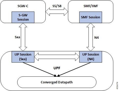
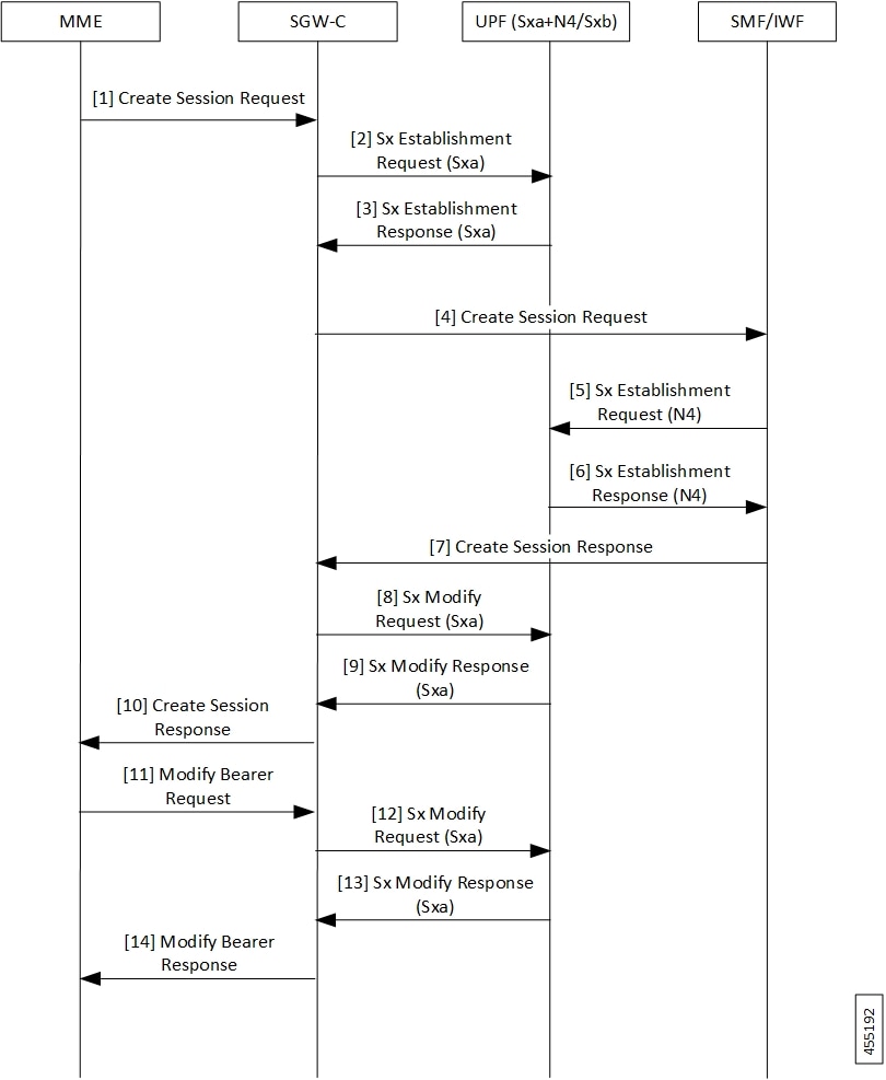
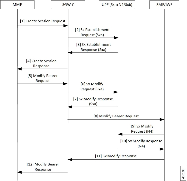
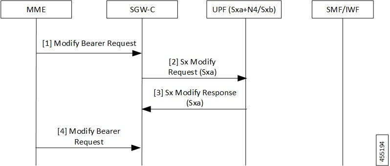
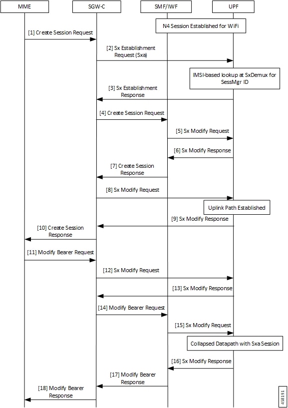
Support added for WiFi to LTE handover, and configuration to enable Converged Datapath feature at UPF.

2021.02.0

First introduced.

2021.01.0

Feature Description

The Converged Datapath feature allows interconnection of the same UE’s session at UPF instance with SGW-C/cnSGW and Session Management Function (SMF)/Inter-Working Function (IWF) to build converged/collapsed datapath and achieve higher throughput. With this feature:

  • The UP/UPF selection logic is enhanced to aid same node selection on SGW-C/cnSGW and SMF.

  • The SxDemux selects the same Session Manager (SessMgr) instance based on existing session of N4 or Sxa respectively.

  • The Sxa session and N4 session correlation is done at SessMgr.

  • The datapath is allowed to be collapsed in the forwarding plane.

  • Extra hop in subscriber’s datapath is eliminated, resulting in reduced latency and improved user experience.

Architecture

As part of this feature, there are two sessions on the same UPF instance established by SGW-C/cnSGW and SMF. Once they are established, the software logic determines the peer session so that the converged/collapsed datapath for packet processing is possible at the UPF node.

How it Works

This section describes how the feature works.

SxDemuxMgr

In distributed architecture of UP/UPF, sessions (Sxa or N4) run on different SessMgr instances. To support collapsing or converging the sessions to a single SessMgr, the SessMgr instance is selected by both sessions during establishment.

At SxDemux, when Sx Establishment Request (Sxa or N4) is received for selecting the SessMgr instance, it’s parsed for finding the SessMgr instance from remote F-TEID, where corresponding sessions (N4 or Sxa respectively) are established. The F-TEID, that contains the Tunnel Identifier that is embedded with SessMgr instance, is extracted.

UPF also maintains IMSI entry at SxDemux. IMSI entry has information of SessMgr ID where the current session is hosted. When Converged Datapath feature is enabled, on receiving Sx Session Establishment Request, SxDemux first tries to find the SessMgr ID using F-TEID. If F-TEID is not present, IMSI lookup is done. If both F-TEID and IMSI is not present, then SxDemux doesn't select the same SessMgr ID for Sxa/N4 leg.

SessMgr

There are two sessions, Sxa and N4, that exist on the same SessMgr instance. To converge them, the following logic is used to identify the session:

  • For Uplink Packet: Egress FARs F-TEID matches with Ingress PDRs F-TEID.

  • For Downlink Packet: Ingress FAR’s F-TEID should match with Egress PDR’s F-TEID.

The F-TEID includes both Tunnel Identifier and the endpoint IP address. After the session is identified, the required information is used in datapath to build the converged datapath.

Datapath

After convergence of session occurs at SessMgr, the SessMgr removes the existing Bearer stream (3 tuple) from Fast Path that is installed for Sxa session. It’s established only when flow-level stream (6 tuple), based on received packet, is analyzed.

The uplink packet is received by S-GW ingress PDR endpoint. The downlink packet is forwarded using S-GW Ingress FAR-based outer header.

Charging

UPF supports charging of SMF leg (N4 leg) and S-GW .

Call Flows

This section describes the call flows associated with Converged Datapath feature.

Initial Attach with SGW-C/cnSGW and SMF/IWF

The following illustration describes the initial attach call flow with collapsed UPF.

Table 3. Initial Attach with SGW-C/cnSGW and SMF/IWF Call Flow Description
Step Description
1 Create Session Request (CSReq) is received by SGW-C/cnSGW and it selects the UPF.
2

The SGW-C/cnSGW sends Sx Establishment Request (Sxa) to the UPF. The UPF:

  • Allocates Sxa session

  • Allocates S-GW Ingress and Egress local F-TEID

3 The UPF sends Sx Establishment Response (Sxa) back to SGW-C/cnSGW.
4

The SGW-C/cnSGW sends CSReq to SMF/IWF.

The SMF/IWF selects the same UPF that is selected by SGW-C/cnSGW.

5 The SMF/IWF sends Sx Establishment Request (N4) to the UPF.
6 The UPF sends Sx Establishment Response (N4) to the SMF/IWF.
7 The SMF/IWF sends Create Session Response to the SGW-C/cnSGW.
8

The SGW-C/cnSGW sends Sx Modify Request (Sxa) to the UPF.

The UPF updates P-GW data F-TEID as part of Egress FAR.

The UPF also interconnects Sxa and N4 session using internal logic and removes already-created Bearer Stream (3 tuple).

9 The UPF sends Sx Modify Response (Sxa) to the SGW-C/cnSGW.
10 The SGW-C/cnSGW sends Create Session Response to the MME.
11 The MME sends Modify Bearer Request to the SGW-C/cnSGW.
12

The SGW-C/cnSGW sends Sx Modify Request (Sxa) to the UPF.

The UPF updates eNodeB F-TEID as part of Ingress FAR.

13 The UPF sends Sx Modify Response to the SGW-C/cnSGW.
14 The SGW-C/cnSGW sends Modify Bearer Response to the MME.

5G to 4G Handover with Collapsed UPF

The following illustration describes the 5G to 4G handover call flow with collapsed UPF.

Table 4. 5G to 4G Handover with Collapsed UPF Call Flow Description
Step Description
1

As part of UE initial attach, N4 session is already established with SMF and UPF.

The MME sends Create Session Request (CSReq) to SGW-C/cnSGW. If it’s a handover request, the SGW-C/cnSGW selects the same UPF that is selected by the SMF.

2

The SGW-C/cnSGW sends Sx Establishment Request (Sxa) to the UPF. At UPF:

  • SxDemux selects the same SessMgr instance extracted from the P-GW F-TEID that is received in FAR. Both Sxa and N4 session are on the same SessMgr.

  • Allocates Sxa session

  • Allocates S-GW Ingress and Egress local F-TEID

  • Interconnects Sxa and N4 session using internal logic and doesn’t install Bearer Stream (3 tuple)

3 The UPF sends Sx Establishment Response (Sxa) back to SGW-C/cnSGW.
4 The SGW-C/cnSGW sends Create Session Response to the MME.
5 The MME sends Modify Bearer Request to the SGW-C/cnSGW.
6

The SGW-C/cnSGW sends Sx Modify Request (Sxa) to the UPF.

The UPF updates eNodeB F-TEID for downlink data.

7 The UPF sends Sx Modify Response (Sxa) to the SGW-C/cnSGW.
8 The SGW-C/cnSGW sends Modify Bearer Request to the SMF/IWF.
9

The SMF/IWF sends Sx Modify Bearer Request (N4) to the UPF. The UPF:

  • Updates N4 session FAR towards S-GW with F-TEID

  • Updates TEP entries at VPP with new F-TEID

10 The UPF sends Sx Modify Response (N4) to the SMF/IWF.
11 The SMF/IWF sends Sx Modify Response to the SGW-C/cnSGW.
12 The SGW-C/cnSGW sends Modify Bearer Response to the MME.

Intra S-GW Handover with Collapsed UPF

The following illustration describes the intra-SGW handover call flow with collapsed UPF.

Table 5. Intra S-GW Handover with Collapsed UPF Call Flow Description
Step Description
1

As part of UE initial attach, N4 and Sxa session is already established with SMF and UPF. At UPF, N4+Sxa session exists and are interconnected.

The MME sends Modify Bearer Request to the SGW-C/cnSGW.

The SGW-C/cnSGW updates eNodeB F-TEID in FAR.

2

The SGW-C/cnSGW sends Sx Modify Request (Sxa) to the UPF. The UPF:

  • Updates eNodeB F-TEID for downlink data

  • Updates TEP entries at VPP with new Remove TEID

3 The UPF sends Sx Modify Response (Sxa) to the SGW-C/cnSGW.
4 The SGW-C/cnSGW sends Modify Bearer Response to the MME.

Idle/Active DDN Handling with Collapsed UPF

The following illustration describes the Idle/Active DDN handling with collapsed UPF.

Table 6. Idle/Active DDN Handling with Collapsed UPF Call Flow Description
Step Description
1

As part of UE initial attach, N4 and Sxa session is already established with SMF and UPF. At UPF, N4+Sxa session exists and are interconnected. At MME, the UE goes from Active to Ide state.

The MME sends Release Access Bearer Request to the SGW-C/cnSGW. The SGW-C/cnSGW informs UPF to buffer packets.

2 The SGW-C/cnSGW sends Sx Modify Request (Sxa) to the UPF. The UPF updates FAR action towards eNodeB to buffer state. 6 tuple flows are onloaded for buffering.
3 The UPF sends Sx Modify Response (Sxa) back to SGW-C/cnSGW.
4 The MME sends Release Access Bearer Response to the SGW-C/cnSGW.
5 The ISP/Gi sends the received downlink packet to the UPF. The packet received by UPF at N4 session is passed to interconnect Sxa session for buffering.
6 The UPF sends Usage Report Request (Sxa) to the SGW-C/cnSGW.
7 The SGW-C/cnSGW sends Usage Report Response (Sxa) to the UPF.
8 The SGW-C/cnSGW sends DDN notification to the MME.
9 The MME sends DDN Acknowledgment back to the SGW-C/cnSGW.
10

At MME, the UE moves from Idle to Active. The MME sends Modify Bearer Request to the SGW-C/cnSGW. The SGW-C/cnSGW:

  • Updates eNodeB F-TEID in FAR

  • Updates FAR action to Forward

11

The SGW-C/cnSGW sends Sx Modify Request (Sxa) to the UPF. The UPF:

  • Updates eNodeB F-TEID for downlink data

  • Updates TEP entries at VPP with new Remove TEID

  • Releases buffered packets by finding respective 6 tuple streams

12 The UPF sends Sx Modify Response (Sxa) to the SGW-C/cnSGW.
13 The SGW-C/cnSGW sends Modify Bearer Response to the MME.

IDFT Handling during S1 Handover

The following illustration describes the IDFT handling during S1 handover with collapsed UPF.

Table 7. IDFT Handling during S1 Handover Call Flow Description
Step Description
1

As part of initial attach, N4 and Sxa session is already established with SMF and UPF. S1 handoff is triggered.

The MME sends Indirect Tunnel Request Message to the SGW-C/cnSGW.

2

The SGW-C/cnSGW sends Sx Modify Request (Sxa) to the UPF. At UPF:

  • IDFT PDR is detected at SessMgr

  • New F-TEID is allocated for IDFT tunnel

  • Converged datapath is not required and traffic goes through Slowpath

3 The UPF sends Sx Modify Response (Sxa) to the SGW-C/cnSGW.
4 The SGW-C/cnSGW sends Create Indirect Tunnel Response Message to the MME.
5 The Source eNodeB sends IDFT data packet to the UPF. If there’s no matching 3 tuple stream at UPF, the packet is forwarded to SessMgr.
6 The UPF sends IDFT data packet to the destination eNodeB.

S-GW Relocation with Same SGW-U

The following illustration describes the S-GW relocation with destination S-GW selecting the same UPF.

Table 8. S-GW Relocation with Same SGW-U Call Flow Description
Step Description
1

As part of initial attach, N4 and Sxa session is already established with Source SGW-C/cnSGW, SMF/IWF, and UPF.

The MME sends Create Session Request to the destination SGW-C/cnSGW.

2 The destination SGW-C/cnSGW sends Sx Establishment Request (Sxa) to the UPF. The UPF links new Sxa session with the N4 session for uplink packets (Slowpath).
3 The UPF sends Sx Establishment Response (Sxa) to the destination SGW-C/cnSGW.
4 The destination SGW-C/cnSGW sends Create Session Response to the MME.
5 The MME sends Modify Bearer Request (eNodeB F-TEID) to the destination SGW-C/cnSGW.
6 The destination SGW-C/cnSGW sends Sx Modify Request (Sxa) to the UPF.
7 The UPF sends Sx Modify Response (Sxa) to the destination SGW-C/cnSGW.
8 The destination SGW-C/cnSGW sends Modify Bearer Request to the SMF/IWF.
9 The SMF/IWF sends Sx Modify Request (N4) to the UPF. The UPF switches downlink tunnel and links the N4 session with the new Sxa session.
10 The UPF sends Sx Modify Response (N4) to the SMF/IWF.
11 The SMF/IWF sends Modify Bearer Response to the destination SGW-C/cnSGW.
12 The destination SGW-C/cnSGW sends Modify Bearer Response to the MME.
13 The MME sends Delete Session Request to the source SGW-C/cnSGW.
14 The source SGW-C/cnSGW sends Sx Delete Session Request to the UPF.
15 The UPF sends Sx Delete Session Response to the source SGW-C/cnSGW.
16 The source SGW-C/cnSGW sends Delete Session Request to the MME.

WiFi to LTE Handover

The following illustration describes the WiFi to LTE handover call flow.

Table 9. WiFi to LTE Handover Call Flow Description
Step Description
1

N4 Session is established for WiFi between SMF/IWF and UPF.

The MME sends Create Session Request (relocating to 4G) to the SGW-C/cnSGW.

2 The SGW-C/cnSGW sends Sx Session Establishment Request (No F-TEID) to the UPF.
3

IMSI-based lookup is done at SxDemux for SessMgr ID.

The UPF sends Sx Establishment Response to the SGW-C/cnSGW.

4 The SGW-C/cnSGW sends Create Session Request to the SMF/IWF.
5 The SMF/IWF sends Sx Modify Request with new Uplink RB PDR to the UPF.
6 The UPF sends Sx Modify Response to the SMF/IWF with new TEID for Uplink data.
7 The SMF/IWF sends Create Session Response to the SGW-C/cnSGW.
8 The SGW-C/cnSGW sends Sx Modify Request to the UPF with updated Uplink FAR.
9

Uplink path is established.

The UPF sends Sx Modify Response to the SGW-C/cnSGW.

10 The SGW-C/cnSGW sends Create Session Response to the MME.
11 The MME sends Modify Bearer Request to the SGW-C/cnSGW.
12 The SGW-C/cnSGW sends Sx Modify Request to the UPF with eNodeB TEIDs.
13 The UPF sends Sx Modify Response back to the SGW-C/cnSGW.
14 The SGW-C/cnSGW sends Modify Bearer Request to the SMF/IWF.
15 The SMF/IWF sends tunnel switch Sx Modify Request to the UPF.
16

Collapsed datapath with Sxa session is established at UPF.

The UPF sends Sx Modify Response to the SMF/IWF.

17 The SMF/IWF sends Modify Bearer Response to the SGW-C/cnSGW.
18 The SGW-C/cnSGW sends Modify Bearer Response to the MME.

Limitations

The following are the known limitations of the feature:

  • If Sxa leg is of one user-plane-service and N4 leg is of another user-plane-service, then datapath won't be collapsed.

  • If Sxa leg is under one context and N4 leg is in another context, then datapath can't be collapsed.

  • The S-GW part of the show subscribers user-plane-only full all CLI output doesn't display ToS-marked Uplink and Downlink packets.

  • For the S-GW part of the show user-plane-service statistics rat all CLI output, the session statistics for Unknown is incremented, however, the data statistics aren't incremented under RAT-type Unknown.

  • Lawful Intercept for S-GW isn't supported.

  • S-GW bearer inactivity timeout isn't honored, as it's determined by S-GW URR for which processing isn't done for collapsed datapath.

  • If S-GW leg of call is locally purged for converged session, then the UPF continues to send data toward eNodeB.

Charging for Converged Calls

Table 10. Feature History
Feature Name

Release Information

Description

Charging Support for Converged Calls 2024.02.0

UPF supports S-GW Charging Data Record (CDR) volume reporting for converged calls. This feature allows you to use these CDRs for reporting and charging during inbound LBO roaming scenario.

This feature introduces a new CLI command converged-sxa-usage-reporting in the ACS Service configuration, to generate the usage report with volume count.

Default Setting: Disabled – Configuration Required to Enable

Feature Description

For a converged call, SGW-U sends the usage report to SGW-C based on which the SGW-C generates the CDR. You can enable this feature through the converged-sxa-usage-reporting CLI command. Once enabled, SGW-U sends a usage report with volume accounting to SGW-C, based on which the SGW-C generates the CDR.

How it Works

For the SGW-U to update a volume report, the URR linking happens between SGW-U bearer URR and PGW-U, UPF bearer, or SDF level URRs. While the reconciliation of charging on UPF, the reconciliation of charging on Sxa also happens simultaneously. Depending on the threshold triggers, the SGW-U generates the usage report. Examples of threshold triggers are time threshold, volume threshold, and Query URR. Then, SGW-U sends the usage report to SGW-C based on which the SGW-C generates CDR.

To update the volume count for SGW-U bearer URRs along with PGW-U or UPF URRs for a converged call, the following process happens:

  • The reference pointer of SGW-U default bearer URR is stored at PGW-U or UPF default bearer URR.

  • The reference pointer of SGW-U dedicated bearer URRs is stored at SDF level URRs of the corresponding dedicated bearer of PGW-U or UPF.

While reconciling the LC count, the URRs of PGW-U or UPF and SGW-U bearer are traversed. Then, the volume counts are updated for both the call ID URRs.


Note


  • If a call is established as a converged call, then the reference pointer of SGW-U bearer URR is stored at PGW-U, UPF bearer, or SDF level URR while call convergence.

  • In the case of S-GW relocation from a nonconverged call to a converged call, the URR linking happens. The URR linking implies that the reference pointer of the SGW-U bearer URR is stored at PGW-U, UPF bearer, or SDF level URR.

  • In the case of S-GW relocation from a converged call to a nonconverged call, the URR delinking happens. The URR delinking implies that the reference pointer of SGW-U bearer URR is removed from PGW-U, UPF bearer, or SDF level URR.

  • In the case of recovery, recreation of the link happens, which implies that the reference pointer of SGW-U URR is stored at PGW-U or UPF URR during recovery to maintain consistent behavior.


Limitations

The charging for converged calls feature has the following limitations:

  • Volume reporting in S-GW URRs is based on the corresponding PGW-U or UPFs URR usage count. For example, the uplink packets that are dropped due to P-GW processing aren’t accounted in the Sxa call.

  • RA or RS packet charging doesn't happen at UPF. As the Sxa usage report depends on the UPF, the RA or RS packets aren't accounted for charging on the Sxa call.

  • Multiple bearers using the same URR ID lead to inconsistency in the usage report that is generated as Sxa.

  • For converged calls, if packets aren’t charged at N4 leg, then these packets aren't charged at Sxa as well.

  • Charging for predefined rules on a dedicated bearer isn't supported for converged calls.

  • When the call is getting converged, the feature configuration, either enabled or disabled, remains the same until the duration of the existing call. The change in configuration is applicable from the new call onwards. If the feature is enabled, the charging continues for existing and new URRs. However, if the feature is disabled, the charging doesn't happen for the existing and new URRs.

Configuring eGCDR

The eGCDR configuration is required on PGW-U or UPF to create static default bearer URR at PGW-U or UPF.

The following is a sample configuration:

config
   active-charging service ACS
       rulebase starent
           billing-records egcdr 
   end

Configuring GTPP Group

The GTPP group configuration is required on PGW-U or UPF to create static default bearer URR at PGW-U or UPF.

The following is a sample configuration:

config
   context ISP
      apn intershat
          gtpp group my_grp
   end

Generating Usage Report with Volume Count for Converged Sxa Calls

To generate the usage report with volume count for Sxa call, use the following sample configuration:

config 
   active-charging service service_name 
      converged-sxa-usage-reporting  
         end 

NOTES:

  • converged-sxa-usage-reporting : Enable generation of usage reports for converged SxA calls. To disable this functionality, add the no converged-sxa-usage-reporting syntax. The default value is no converged-sxa-usage-reporting .

Configuration Example

The following is an example configuration of generation of usage report for the converged Sxa call:

config
  active-charging service ACS
     converged-sxa-usage-reporting
  end

Configuring Converged Datapath

This section describes the CLI commands available in support of the feature.

Enabling Converged Datapath at UPF

Use the following configuration to enable Converged Datapath at UPF.

configure 
   user-plane converged-mode 
   end 

NOTES:

  • user-plane : Specifies the UPF related to the configuration.

  • converged-mode : Specifies the collapse datapath of Sxa and N4 calls.

  • By default, the CLI is disabled.

  • It is recommended to add the CLI in boot configuration.

Configuring Remote Peers for Sxa and N4

Use the following CLI commands to configure remote peers for Sxa and N4 interface.

configure 
   control-plane-group group_name 
      peer-node-id ipv4-address ipv4_address interface n4 
      peer-node-id ipv4-address ipv4_address  
      end  

Configuring User Plane Service for Sxa and N4

Use the following CLI commands to configure UP Service for Sxa and N4 interface.

configure 
   user-plane-service service_name 
      associate gtpu-service gtpu_service upf-ingress 
      associate gtpu-service gtpu_service sgw-ingress 
      associate gtpu-service gtpu_service sgw-egress 
      associate gtpu-service gtpu_service cp-tunnel 
      associate sx-service sx_service  
      associate control-plane-group group_service  
      end  

Monitoring and Troubleshooting

Show Commands and/or Outputs

This section provides information about the show CLI commands and/or outputs available in support of the Converged Datapath feature.

show subscribers user-plane-only all

The output of this CLI command is enhanced to display the following fields to indicate if the session is converged or non-converged:

  • Converged

  • Non Converged

show subscribers user-plane-only full all

The output of this CLI command is enhanced to display the following fields:

  • Converged Session

  • Converged Peer Callid

show user-plane-service statistics all

The output of this CLI command is enhanced to display the following fields:

  • Converged Data Session PDNs:

    • Active

    • Setup

    • Released