N4 Session Management, Node Level, and Reporting Procedures

This chapter covers the following topics:

Feature Summary and Revision History

Summary Data

Table 1. Summary Data
Applicable Product(s) or Functional Area 5G-UPF
Applicable Platform(s)

VPC-SI

SMI

Feature Default Setting Enabled – Always-on
Related Changes in this Release Not Applicable
Related Documentation Not Applicable

Revision History

Revision Details Release

The show user-plane-service statistics all command has been enhanced to display PFCP IEs received in Sx Establishment or Modification messages over N4 interface.

2023.01

2021.02.2

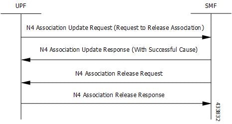
PDN Update procedure is introduced in this release.

2021.02.0

First introduced.

2020.02.0

Feature Description

N4 Session Management, Node Level, and Reporting Procedures

N4 Node-level Procedures

The N4 Node-level procedures in User Plane Function (UPF) involves the following processes:

  • N4 Association Setup Procedure – The procedure used for setting up an N4 association between the Session Management Function (SMF) and UPF.

  • N4 Association Update Procedure – The procedure used for modifying an existing N4 association between the SMF and UPF.

  • N4 Association Release Procedure – The procedure used for terminating the N4 association between the SMF and UPF.

  • N4 Heartbeat Procedure – The procedure used for sending and receiving the Heartbeat request and response.

  • N4 Reporting Procedure – The procedure used for reporting echo request and response for the GTP-u path failure.

N4 Session Management

N4 session management procedures are used to control the functionality of the UPF. SMF can create, update, and remove the N4 session context in the UPF, which is described in 3GPP TS 23.501, clause 5.8.2.

The following procedures are performed in N4 Session Management:

  • N4 Session Establishment

  • N4 Session Modification

  • N4 Session Deletion

NOTE: The SMF initiates all the above procedures.

N4 Session/Node-level Reporting Procedures

Whenever the data path between UPF and gNB is down, it is detected and reported to the SMF for corrective actions. The mechanism to detect and report it to SMF is clearly defined in 3GPP specifications. The reporting happens per GTP-u Tunnel level or per GTP-u endpoint level.

Relationships

The following features support the N4 session management, node level, and reporting procedures.

End Marker Support

The UPF sends the End Marker packets to support the reordering function in the target Radio Access Network (RAN). The UPF constructs the End Marker packets that are required for the reordering function.

Constructing the End Marker Packets through UPF

At the time of the handover procedure, the PDU session for the UE – which comprises of an UPF node – acts as a PDU session anchor and an intermediate UPF terminating N3 reference point. The SMF sends an N4 Session Modification Request message with the new AN Tunnel Info of NG RAN to specify the UPF to switch to the N3 paths. In addition, the SMF also specifies the UPF to send the End Marker packets on the old N3 user plane path.

After the UPF receives the indication, the End Markers are constructed and sent to each N3 GTP-U tunnel toward the source NG RAN, after sending the last PDU on the old path.

UEs IPv4, IPv6, and IPv4v6 Support

The UPF supports UE's IPv4, IPv6, and IPv4v6 sessions.

The N4 Session Establishment and Modification procedure for IPv6 sessions is the same as for IPv4 sessions. After the session is established, the SMF sends Router Advertisement (RA) message to UE announcing the IPv6 prefix to be used for traffic. Optionally, to get the IPv6 parameter from SMF faster, the UE can also initiate IPv6 Router Solicitation (RS).

The N4 Session Establishment and Modification procedure for IPv4v6 Session are similar to the IPv4 or IPv6 sessions except for the allocation of two UE IP addresses - one for IPv4 and the other for IPv6. The SMF sends the Router Advertisement message to the UE announcing the IPv6 prefix used for traffic after the session is established. Optionally, the UE can also initiate the IPv6 Router Solicitation to receive the IPv6 parameter from the SMF quickly.

How it Works

This section describes the N4 node-level, session management, and reporting procedures and associated call flows.

N4 Node-level Procedure Call Flows

N4 Association Setup Procedure Call Flow

The N4 Association Setup procedure creates the N4 association between the SMF and the UPF, which enables the SMF to use the UPF resources to establish N4 sessions. The N4 association setup procedure involves the following steps:

  1. The UPF initiates the procedure by sending N4 Association Setup Request to the SMF.

  2. The SMF sends an N4 Association Setup Response after it receives the request from the UPF.

The following call flow describes the UPF-initiated N4 Association Setup procedure:

The UPF sends the following PFCP Association Setup Request:

  • Node ID (UPF).

  • Supported optional features in UPF. The UPF supports F-TEID allocation and release, sending of End Marker, and so on.

N4 Association Update Procedure Call Flow

The N4 Association Update procedure modifies an existing N4 association between the SMF and the UPF. It can be initiated either by the UPF or by the SMF to update the supported features or available UPF resources.

The following call flow depicts the SMF-initiated N4 Association Update procedure:

The following call flow depicts the UPF-initiated N4 Association Update procedure:

N4 Association Release Procedure Call Flow

The N4 Association Release procedure terminates the N4 association between the SMF and the UPF. It can be initiated either by the SMF or by the UPF. The UPF requests the SMF to perform the release of PFCP association by sending a PFCP Association Update Request. The SMF then initiates a PFCP Association Release Request to release the PFCP association.

The following call flow depicts the SMF-initiated N4 Association Release procedure:

The following call flow depicts the UPF-initiated N4 Association Release procedure:

N4 Heartbeat Procedure

The PFCP Heartbeat procedure includes the following messages:

  • Heartbeat Request

  • Heartbeat Response

N4 Session Management Procedures Call Flows

The following section describes the N4 Session Management procedures.

N4 Session Establishment Call Flow

N4 Session Establishment is used to create the initial N4 session context for a PDU session at the UPF. SMF assigns a new N4 session ID and provides it to the UPF. The N4 session ID is stored by both entities and used to identify the N4 session context during their interaction. SMF also stores the relation between the N4 session ID and PDU session for a UE.

Step Description
1 SMF receives the trigger to establish a new PDU session or change the UPF for an established PDU session.
2 SMF sends an N4 session establishment request message to the UPF that contains the structured control information which defines how the UPF needs to behave.
3 UPF responds with an N4 session establishment response message containing any information that the UPF has to provide to the SMF in response to the control information received.
4 SMF interacts with the network function which triggered this procedure. For example, AMF or PCF.

N4 Session Modification Call Flow

N4 Session Modification is used to update the N4 session context of an existing PDU session at the UPF, which is executed between SMF and UPF whenever PDU session-related parameters have to be modified.

Step Description
1 SMF receives the trigger to modify the existing PDU session.
2 SMF sends an N4 session modification request message to the UPF which contains the update for the structured control information that defines how the UPF needs to behave.
3 UPF identifies the N4 session context to be modified by the N4 session ID and updates the parameters of this N4 session context according to the list of parameters that are sent by the SMF. UPF responds with an N4 session modification response message containing any information that the UPF has to provide to the SMF in response to the control information received.
4 SMF interacts with the network entity which triggered this procedure. For example, AMF or PCF.

N4 Session Delete Call Flow

N4 Session Delete is used to remove the N4 session context of an existing PDU session at the UPF.

Step Description
1 SMF receives the trigger to remove the N4 session context for the PDU session.
2 SMF sends an N4 session delete request message to the UPF.
3 UPF identifies the N4 session context to be removed by the N4 Session ID and removes the whole session context. UPF responds with an N4 session delete response message containing any information that the UPF has to provide to the SMF.
4 SMF interacts with the network entity which triggered this procedure. For example, AMF or PCF.

N4 Session/Node Level Reporting Procedure Call Flows

Session Level Reporting Due to the GTP-u Error Indication Call Flow

When the UPF receives the GTP-u Error Indication from gNB, it detects the PFCP session and sends the PFCP Session Report request to the SMF handling that session along with the Error Indication Report IE. The Error Indication IE also includes the remote F-TEID IE, which contains the GTP-u peer address and the TEID received from the GTP-u Error Indication IE.

Step Description
1 A PFCP session is established and the data traffic starts running.
2 When gNB clears up the TEID details locally for some reason, it sends the GTP-u Error Indication to UPF for unknown TEID.
3 Once the Error Indication is received, the UPF identifies the PFCP session and sends the PFCP session report request to the SMF.
4 The session report request contains the TEID and the remote IP address from where the Error Indication is received.

Node-level Reporting Procedure due to GTP-u Path Failure Call Flow

When the UPF enables GTP-u Echo procedure for GTP-u endpoints and identifies a data path failure because of no response, it sends a PFCP Node Report Request to the SMF. The Node Report Type in the PFCP Node Report Request is set to User Plane Path Failure Report when it is sent to the SMF. The Node Report procedure includes only the peer IP address in Remote GTP-u Peer IE – the child IE of the User Plane Path Failure IE – since it is not specific to any PFCP session.

Step Description
1 Once the PFCP session is established and GTP-u Echo procedure is configured, UPF initiates the GTP-u Echo Request for each peer with at least one GTP-u Tunnel.
2 If there is no GTP-u Echo Response received after a specified number of retries, then the UPF sends the PFCP Node Report Request to the SMF.
3 Only the peer IP address is sent in the Node Report request since it is not a GTP-u tunnel-specific failure.
4 Once the message is received, the SMF sends a Delete and Modify request for all the PFCP Sessions for that gNB to UPF.

PDN Update Procedure - eNodeB F-TEIDu

Feature Description

For S-GW or SAEGW, a procedure to initiate an N4/Sx Modification Request is implemented for:

  • eNodeB F-TEIDu update

  • Release Access Bearer (RAB) Request for an eNodeB release

How it Works

The PDN update procedure includes the following events for an eNodeB F-TEIDu Update/Release:

  • For eNodeB F-TEIDu Update:

    1. The SGW-C initiates N4/Sx Session Modification Request toward SGW-U on receiving a Modify Bearer Request for eNodeB F-TEIDu Update from the MME.

    2. The N4/Sx Modification Request for eNodeB F-TEIDu update contains Update FAR with Apply Action as “Forward” and the updated eNodeB IPv4/IPv6 address in Outer Header Creation, which is a part of the Update Forwarding Parameters IE.

  • For eNodeB F-TEIDu Release:

    1. The SGW-C initiates N4/Sx Modification Request toward SGW-U on receiving a RAB Request from the MME.

    2. RAB is a UE-level message. If the UE has multiple PDN connections, then the N4/Sx Modification Request is sent to each PDN connection separately.

    3. SGW-C initiates N4/Sx Session Modification Request toward SGW-U for the N4/Sx session with Update FAR with destination interface as ACCESS. Update FAR contains: FAR ID and Apply Action as Drop. FAR with the destination interface as CORE is not updated.

Standards Compliance

The PDN Update procedure complies with the following standards:

  • 3GPP TS 23.401: "General Packet Radio Service (GPRS) enhancements for Evolved Universal Terrestrial Radio Access Network (E-UTRAN) access".

  • 3GPP TS 29.274: "3GPP Evolved Packet System (EPS); Evolved General Packet Radio Service (GPRS) Tunnelling Protocol for control plane (GTPv2-C); Stage 3".

  • 3GPP TS 29.244: “Interface between the Control Plane and the User Plane of EPC ".

  • 3GPP TS 23.214: "Architecture enhancements for control and user plane separation of EPC nodes; Stage 2"

  • 3GPP TS 23.714: "Study on control and user plane separation of EPC nodes"

UEs IPv4, IPv6, and IPv4v6 Support Call Flows

N4 Session Establishment and Modification Procedure for IPv6 Call Flow

The following call flow provides a high-level description of the N4 session establishment and modification procedure for IPv6.

Step Description
1 The SMF receives the trigger to establish a new PDU session or change the UPF for an established PDU session.
2 The SMF sends N4 Session Establishment Request message to the UPF, in which Create PDR IE has IPv6 UE address, and SDF filter has IPv6 filters to select the PDRs.
3 The UPF responds with an N4 Session Establishment Response message containing any information that the UPF must provide to the SMF in response to the control information received.
4 The SMF interacts with the network function and triggers to modify the PDU session.
5 The SMF sends an N4 Session Modification Request message to the UPF that contains the update for the structured control information which defines how the UPF needs to behave.
6 The UPF identifies the N4 session context to be modified by the N4 Session ID. Then, the UPF updates the parameters of this N4 session context according to the list of parameters sent by the SMF. The UPF responds with an N4 session modification response message containing any information that the UPF must provide to the SMF in response to the control information received.
7 An extra procedure is required for IPv6 sessions, which is Router Solicitation (RS) and Router Advertisement (RA). After the session is established, UE sends the RS message to network to get the link layer address. The UPF forwards this message to SMF. The SMF sends RA message with required parameters to configure the IPv6 address of UE.
8 The RS and RA between UPF and SMF is GTP-u encapsulated and SMF sends an extra pair of PDRs during session establishment and modification procedure, in which GTP-u Tunnel IDs are exchanged for GTP-u tunneling.
9

The additional pair of PDRs that are sent from the SMF are as follows:

  • One PDR has Source interface as Access, and Destination Interface as CP-Function, to forward IPv6 RS from UE to SMF. The SDF filter is present so that UPF can select this PDR for IPv6 RS from UE

  • Example: Permit in 58 from any tp ff01::2 any

  • Another PDR has source interface as CP-Function, and Destination Interface as Access, to forward the IPv6 RA from SMF to UE. The SDF filter is present so that UPF can select this PDR for all the IPv6 RAs from SMF.

  • Example: Permit out 58 from any to ff01::2 any

10 After RS and RA procedure is completed, the UE sends IPv6 traffic to PDN.

N4 Session Establishment and Modification Procedure for IPv4v6 Call Flow

The following call flow provides a high-level description of the N4 session establishment and modification procedure for IPv4v6.

The IPv4v6 session establishment and modification procedure are similar to the IPv6 session establishment and modification procedure, except for the following procedures:

Step Description
1 In the session establishment request, a PDR IE is created to include both IPv4 and IPv6 UE addresses. The SDF filter also includes the IPv4 and IPv6 filters for selecting the PDRs.
2 When the IPv6 address is assigned to the UE, an extra procedure – Router Solicitation and Router Advertisement – is required. The UE sends the Router Solicitation message to the network to receive the link layer address, once the session is established. The UPF forwards this message to the SMF and the SMF sends the Router Advertisement Message with the required parameters for configuring the IPv6 address of the UE.
3 The RS/RA between UPF and SMF is GTP-u encapsulated. In addition, the SMF sends an extra pair of PDRs during session establishment and modification procedure, in which the GTP-u tunnel IDs are exchanged for GTP-u tunneling.
4

The additional pair of PDRs that are sent from the SMF are as follows:

  • For forwarding IPv6 Router Solicitation from UE to SMF, one PDR’s source interface is set to access, and its destination interface is set to CP-Function. The SDF filter is present in such a way that the UPF selects this specific PDR for the IPv6 Router Solicitation from the UE.

  • For instance, permit in 58 from any to ff01::2 any.

5 The UE sends the IPv6 traffic to PDN once the RS/RA procedure is complete.
6 No additional procedures are required for the IPv4 traffic for this PFCP session.

Configuring the N4 Session/Node Level Reporting Procedures

This section describes how to configure the N4 Session/Node Level Reporting procedures.

Enabling the GTP-u Echo Request Procedure

The existing CLI (Command Line Interface) in gtpu-service is used to enable the GTP-u Echo request procedure.


configure 
   gtpu-service service_name 
      echo-interval seconds 
      echo-retransmission-timeout seconds 
      max-retransmissions num 
      path-failure detection-policy gtp echo 
      end 

NOTES:

  • gtpu-service service_name : Creates a GTP-u service enters the GTP-u Service Configuration Mode for the current context. service_name specifies the name of the GTP-u service.

  • echo-interval seconds : Configures the rate at which GTP v1-u echo packets are sent. seconds specifies the number of seconds between the sending of a GTP-uv1 echo packet. It must be an integer in the range of 60–3600.

  • echo-retransmission-timeout seconds : Configures the timeout for GTP-u echo message retransmissions for this service. seconds specifies the echo retransmission timeout, in seconds, for the GTP-u service. It must be an integer in the range of 1–20. The default value is 5.

  • max-retransmissions num : Configures the maximum retry limit for GTP-u echo retransmissions. num specifies the number of GTP-u echo message retransmissions allowed before triggering a path failure error condition. It must be an integer in the range of 0–15.

  • path-failure detection-policy gtp echo : Configures a path failure detection policy on GTP-u echo messages that have been retransmitted the maximum number of retry times. gtp echo sets the detection policy to detect a failure upon reaching the maximum number of GTP-u echo message retransmissions.

The following is a sample configuration for enabling GTP-u Echo request procedure.

configure
   gtpu-service n3-gtpu-service
   echo-interval 60
   echo-retransmission-timeout 5
   max-retransmissions 5
   path-failure detection-policy gtp echo
   end

Verifying the N4 Session/Node Level Reporting Procedure Configuration

This section describes how to verify the N4 Session/Node Level Reporting Procedure configuration.

N4 Session Node Level Reporting Procedure OA and M Support

Use the show gtpu statistics command to display the GTP-u statistics for Error Indication and GTP-u Echo Request and Response. The following is a sample output from the show gtpu statistics command.
show gtpu statistics
Path Management Messages:
    Echo Request Rx:                  0 Echo Response Rx:            7
    Echo Request Tx:                 19 Echo Response Tx:            0
    SuppExtnHdr Tx:                  0  SuppExtnHdr   Rx:            0

  Peer Stats:
    Total GTPU Peers:                              1
    Total GTPU Peers with Stats:                   1

  Tunnel Management Messages:
    Error Indication Tx:                           0
    Error Indication Rx:                           0
    Error Indication Rx Discarded:  
Use the show sx-service statistics all command to display the Node report request and response statistics. The following is a sample output of the show sx-service statistics all command.
show sx-service statistics all
Node Report Request:
 Total TX:                            1   Total RX:                         0
 Initial TX:                          1   Initial RX:                       0
 Retrans TX:                          0   Retrans RX:                       0
 No Rsp received TX:                  0   Discarded:                        0

Node Report Response:
 Total TX:                            0   Total RX:                         1
 Initial TX:                          0   Initial RX:                       1
 Accepted:                            0   Accepted:                         1
 Denied:                              0   Denied:                           0
 Retrans TX:                          0   Discarded:                        0

Use the show user-plane-service statistics all command to display the statistics of N4 PFCP message parameters. The following is a sample output of the show user-plane-service statistics all command.

show user-plane-service statistics all
N4 Statistics:
    URR : Created        :              0
          Deleted        :              0
          Queried by ID  :              0
          Queried by all :              0
          Total Queried  :              0
    FAR : Created        :              0
          Updated        :              0
          Removed        :              0
    PDR : Predef rule    :              0

Note


Statistics are cumulative, and are displayed as a total of all session managers.


The descriptions of the fields are as follows:

  • URR Created: Displays the total number of URRs created either locally or as requested by the SMF.

  • URR Deleted: Displays the total number of URRs removed either locally or as requested by the SMF.

  • URR Queried by ID: Displays the total messages received to query a subset of URRs with their specific IDs.

  • URR Queried by all: Displays the total messages received to query all the URRs of a session.

  • URR Total Queried: Displays the total number of URRs reported to the SMF in response to "Queried by ID" and "Queried by all".

  • FAR Created: Displays the total number of FARs created.

  • FAR Updated: Displays the total number of FARs updated.

  • FAR Removed: Displays the total number of FARs removed.

  • PDR Predef rule: Displays the total number of CREATE PDRs that have predefined rules set. For one predefined rule two PDRs are received, and so the counter is updated as 2.


    Note


    Total Predef counter isn’t updated when a predefined rule is removed. SMF only sends Remove PDR message, which doesn’t contain predefined rule name. Also, during HO, for exiting predef rule, PDRs are removed and created again, so it’s counted twice for the same session.


SNMP Traps

The following traps are available to track status and conditions GTP-u path failure.

  • EGTPUPathFailure: This trap is generated when no response is received for GTP-U ECHO requests and data path failure is detected toward a peer EPC Node.

  • EGTPUPathFailureClear: This trap is generated when the data path toward the peer node is available.